

Page 1
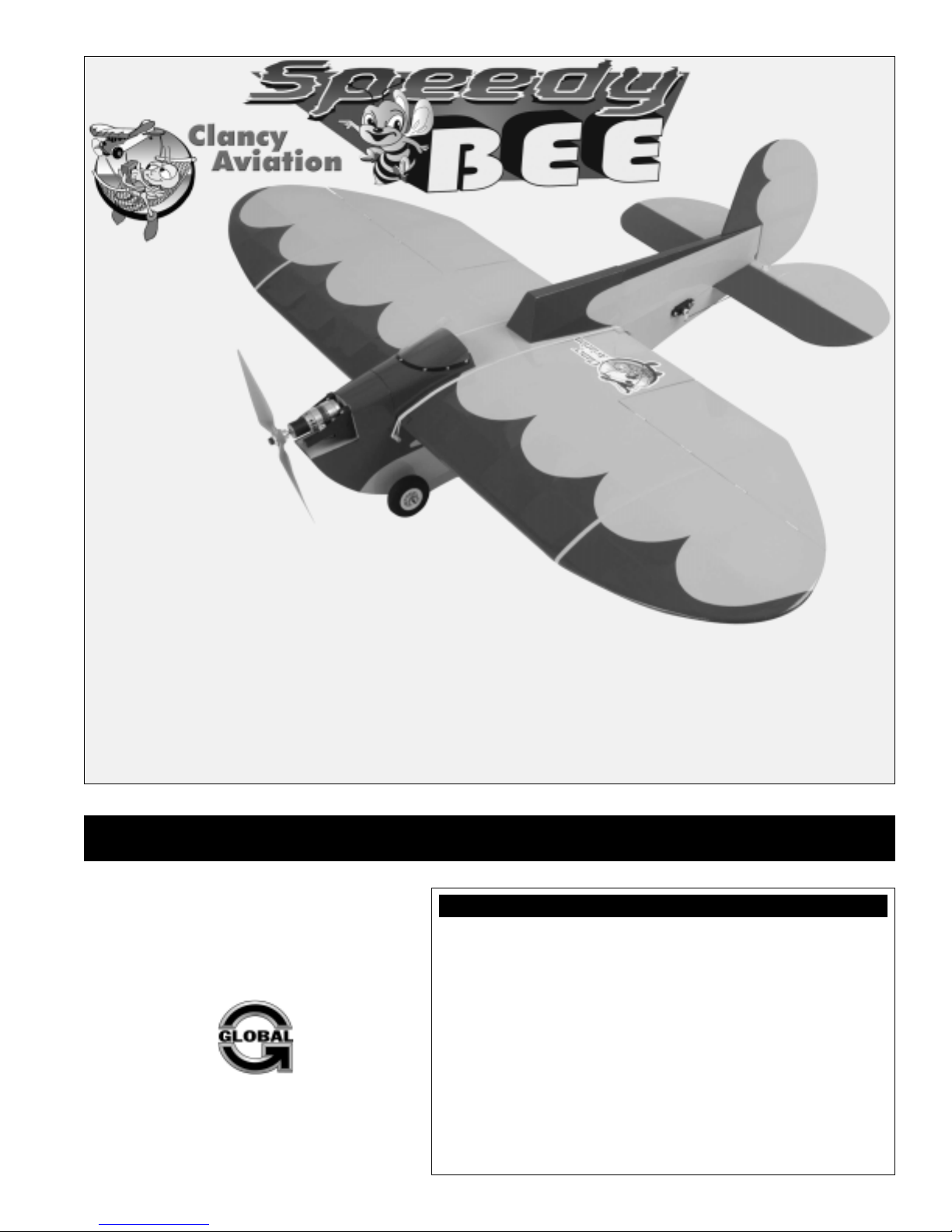
Andy's sporty mid-wing
Bee is now available
as an ARF: the Speedy
Bee Almost Ready-toFly. This design was
originally reviewed in the
June 1998 RCM. Since
then, Clancy Aviation has
made several upgrades, making
this one of Andy's favorite ARFs
so far! We've added an access
door to the bottom of the fuselage
to make battery installation easier if flying it as an electric. It still
features the rubber band retained wing and now has the engine mounted
to the fuselage. We also eliminated the aileron bellcrank linkage and now use
separate aileron servos for each aileron, allowing pilots with computer radios and
mixing to be able to experiment with aileron/flap mixes. The construction itself is all laser-cut
and built on special jigs for precision. This provides superior alignment and performance. And we ONLY use REAL iron-on
covering material.
The Speedy Bee ARF is a 4-channel, mid-wing, wood-airframe design that resembles a golden age racer. The wing span is 52"
with a huge chord like the Lazy Bee. The Speedy Bee ARF wing is flat across the top, but gets some dihedral benefit from the
bottom surface taper. The ailerons are very large (often referred to as "barn door" ailerons) for better control at slow speeds, yet
the Speedy Bee ARF is our most aerobatic Bee: side slips, inverted flight, knife-edges and spins are possible. It's fast, fun, and
unique. It's the Speedy Bee ARF!
INSTRUCTIONS FOR ASSEMBLY
The Clancy Aviation Speedy Bee ARF is distributed
exclusively by Global Hobby Distributors
18480 Bandilier Circle, Fountain Valley, CA 92708
All contents copyright © 2005, Global Hobby Distributors
Version V1.0 February 2005
SPEEDY BEE ARF SPECIFICATIONS:
●
Wing Span: 52 Inches (1315mm)
●
Wing Area: 596 Square Inches (38.6dm2)
●
Length: 37 Inches (940mm)
●
Weight RTF: 49 Ounces (1400gr)
●
Wing Loading: 12 Ounces/Square Foot (36.27gr/dm2)
●
Functions: Ailerons, Elevator, Rudder and Throttle
●
Engine Required: .20 - .28 Two-Stroke or .20 - .30 Four-Stroke
●
Radio Required: 4 Channel or More w/5 Micro Servos and Micro RX
Recommended Electric Power System:
●
Multiplex Brushless BL480/4G with APC 10 x 7E Propeller
●
3C or More LiPO Flight Battery with 40 Amp ESC
1
Kit Product Number 222210
Page 2

TABLE OF CONTENTS
Safety Warning ...................................................................................... 2
Introduction ............................................................................................ 3
Customer Service Information ..............................................................3
Section 1: Our Recommendations ....................................................... 4
Section 2: Tools and Supplies Required ............................................. 5
Section 3: A Note About Covering ....................................................... 5
Section 4: Kit Contents ........................................................................ 6
Section 5: Lithium Polymer Battery Warnings ..................................... 7
Section 6: Wing Assembly ................................................................... 8
Section 7: Wing Mounting ..................................................................10
Section 8: Wing Deck Installation ......................................................13
Section 9: Horizontal Stabilizer Installation ....................................... 15
Section 10: Control Surface Hinging ................................................. 17
Section 11: Landing Gear Installation ................................................ 21
Section 12: Engine Installation .......................................................... 22
Section 14: Fuel Tank Assembly and Installation .............................. 27
Section 15: Elevator Control System Installation ..............................29
Section 16: Rudder Control System Installation ............................... 31
Section 17: Aileron Control System Installation ................................32
Section 18: Final Assembly................................................................34
Section 19: Balancing the Speedy Bee ARF .....................................36
Section 20: Control Throws ............................................................... 36
Section 21: Preflight Check and Safety ............................................. 37
Section 22: Replacement Parts ......................................................... 37
Section 23: Electric Motor, ESC and Battery Installation..................38
Product Evaluation Sheet ...................................................................43
Section 13: Throttle Control System Installation ............................... 25
Check out our website for more information on
this and other exciting Clancy Aviation products!
http://clancyaviation.globalhobby.com
SAFETY WARNING
This R/C airplane is not a toy! If misused or abused, it can cause serious bodily injury and/or damage to property. Fly only in open
areas and preferably at a dedicated R/C flying site. We suggest having a qualified instructor carefully inspect your airplane before
its first flight. Please carefully read and follow all instructions included with this airplane, your radio control system and any other
components purchased separately.
FOR YOUR INFORMATION
To make your modeling experience totally enjoyable, we recommend that you get experienced, knowledgeable help with assembly and during
your first flights. Your local hobby shop has information about flying clubs in your area whose membership includes qualified instructors. If there
is no hobby shop in your area, we recommend that you contact the AMA at the address below. They will be able to help you locate a flying field
near you.
Academy of Model Aeronautics
5151 East Memorial Drive
Muncie IN 47302-9252
(800) 435-9262
www.modelaircraft.org
Clancy Aviation guarantees this kit to be free from defects in both material and workmanship at the date of purchase. This does not cover
any component parts damaged by use, misuse or modification. In no case shall Clancy Aviation's liability exceed the original cost of
the purchased kit.
In that Clancy Aviation has no control over the final assembly or material used for final assembly, no liability shall be assumed for any damage
resulting from the use by the user of the final user-assembled product. By the act of using the final user-assembled product, the user accepts all
resulting liability.
OUR GUARANTEE
2
Page 3
INTRODUCTION
Thank you for purchasing the Clancy Aviation Speedy Bee ARF. Before completing the final assembly of your new
airplane, please carefully read through this instruction manual in its entirety. Doing so will ensure your success the
first time around!
SPEEDY BEE ARF FEATURES
●
Prebuilt from High-Quality Balsa and Light Plywood
●
Detailed, Laser-Cut Parts to Maximize Weight Reduction
●
Precovered with Real Iron-On, Heat-Shrink Covering Material
●
Can be Flown with Glow Power or Electric Power - Hardware Included for Both!
●
Classic Bee-Style Shock-Absorbing Main Landing Gear with Steerable Tail Wheel
●
Dual Aileron Servos for Crisp Roll Response
●
Includes a High-Quality Hardware Package
●
Fast and Easy Assembly - Over 80 High-Resolution Digital Photos and Drawings to Guide You
This instruction manual is designed to guide you through the entire assembly process of your new airplane in the least amount of
time possible. Along the way you'll learn how to properly assemble your new airplane and also learn tips that will help you in the
future. We have listed some of our recommendations below. Please read through them before beginning assembly.
●
Please read through each step before beginning assembly.
You should find the layout very complete and straightforward.
Our goal is to guide you through assembly without any of the
headaches and hassles that you might expect.
●
There are check boxes next to each procedure. After you
complete a procedure, check off the box. This will help prevent
you from losing your place.
●
Cover your work table with brown paper or a soft cloth, both
●
Keep a couple of small bowls or jars handy to put the small
parts in after you open the accessory bags.
●
We're all excited to get a new airplane in the air, but take your
time. This will ensure you build a straight, strong and great
flying airplane.
●
If you come across this symbol ☞, it means that this is an
important point or an assembly hint.
to protect the table and to protect the parts.
CUSTOMER SERVICE INFORMATION
If you should find a part missing or damaged, or have any questions about assembly, please contact us at the address below:
Global Services
18480 Bandilier Circle
Fountain Valley, CA 92708
Phone: (714) 963-0329
Fax: (714) 964-6236
Email: [email protected]
CHECK IT OUT! We urge you to come check out our website at http://globalservices.globalhobby.com. There you will find public message
boards frequented by other Clancy Aviation product owners and the Global Services support staff. This is a great place to learn about new
products, get help and suggestions for your product or just simply hang out and chat with people that share your same interests.
To enable us to better serve your needs, please include your email address with any correspondence you send to us. Your email
address will be added to our Customer Service Database so you will automatically receive free updates and tech notices for your
particular product. You will also receive repair status updates (if applicable) and other important information about your product
as it becomes available.
IMPORTANT INFORMATION ABOUT YOUR EMAIL ADDRESS
Global Hobby Distributors will not disclose the information it collects to outside parties. Global Hobby Distributors
does not sell, trade, or rent your personal information to others . Your privacy is important to us.
3
Page 4
SECTION 1: OUR RECOMMENDATIONS
This section describes our recommendations to help you in deciding which types of accessories to purchase for your new
Clancy Aviation Speedy Bee ARF.
Please read through this entire section very carefully. We have provided you with tips and recommendations that, if
followed, will result in a great flying airplane. Failure to follow our recommendations may result in a poor flying airplane.
What Engine Should I Use?
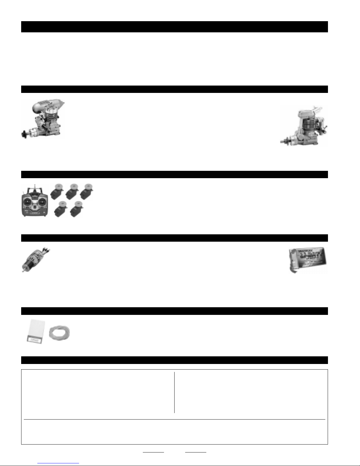
The Speedy Bee ARF is designed to use a .20 - .28 size two-stroke engine or a .20 - .30 size four-stroke engine.
The airplane flies great using engines within the recommended size ranges, although for the
most speed and best aerobatic performance we suggest using an engine at the upper end of the
size range.
We don't suggest using engines larger than those recommended. A larger engine will
typically weigh more and this extra weight could have a negative effect on the airplane's
flight characteristics. A larger engine may also be physically too big to mount onto the firewall.
IF YOU'RE FLYING AT HIGHER ALTITUDES, WE RECOMMEND USING AN ENGINE AT THE HIGH END OF THE RECOMMENDED SIZE RANGE.
What Radio System and Servos Should I Use?
You will need to use a four or more channel radio control system with five mini servos and a
lightweight receiver. A standard four-channel radio or a more sophisticated computer radio would
work equally well. Using a computer radio will allow you to plug each aileron servo separately into
the receiver, allowing you the capability of aileron to flap mixing for outrageous control response.
The Speedy Bee ARF is a small, lightweight airplane, so using mini servos is required. We suggest
using servos that weight no more than 23 grams and have a torque rating of approximately 30oz/sq.in.
Suggested Setup for Electric Flight - See Our Separate Recommendations on Next Page
We know that many customers will want to power their Speedy Bee ARF with an electric power
system, rather than a glow engine. For the most power, lightest weight and best performance, we
suggest using a geared brushless motor, such as the Multiplex BL480/4G with 4.4:1 gearbox,
APC 10 x 7E propeller, M'Troniks 40 amp brushless ESC and WattAge 3 cell 2000mAH LiPO flight pack.
BECAUSE YOU'LL BE USING A BRUSHLESS MOTOR, YOU WILL NEED TO USE A BRUSHLESS MOTOR CONTROLLER,
COMPATIBLE WITH THE MOTOR YOU'VE CHOSEN. DO NOT ATTEMPT TO USE AN ESC DESIGNED FOR BRUSHED
MOTORS WITH A BRUSHLESS MOTOR.
What Else Do I Need?
There really isn't much else that you'll need to finish the airplane. Most of the hardware is included in the kit, so
about the only thing else you'll need is a spinner, two servo extension leads and a Y-Harness (if you're not using
mixing). You'll also need typical modeling supplies, such as foam rubber to protect your receiver and battery,
and fuel tubing. You may need a soldering iron, solder and other related supplies if you're using electric power.
Here's a List of What We Used to Finish Our Speedy Bee ARF
QTY. 1 210630 Magnum XL .28A Two-Stroke Engine
QTY. 1 237152 Magnum 2" Aluminum Spinner w/Adapter Nut
QTY. 1 608360 APC 9 x 6 Propeller
QTY. 5 444245 Cirrus CS-18 Mini Servos
QTY. 2 444713 Cirrus 12" Servo Extensions
QTY. 1 115493 Thunderbolt R/C Long Glow Plug
QTY. 1 115923 Global XX Silicone Fuel Tubing
QTY. 1 868638 Dubro 1/4" Protective Foam Rubber
QTY. 1 867903 Dubro 3/8" Heat-Shrink Tubing
QTY. 1 925040 Beacon # 64 Rubber Bands
✦✦
✦IMPORTANT
✦✦
connector. The part number for the Cirrus servo extensions are compatible with Hitec and JR radio control systems. This item is also available
with connectors that are compatible with Futaba and Airtronics radio control systems.
✦✦
✦ The part number for the Cirrus servos is compatible with all name-brand radio control systems. These servos use a universal
✦✦
4
Page 5
Recommended Items for Brushless Electric Power
QTY. 1 240030 Multiplex BL480/4G Brushless Motor w/Gear Box
QTY. 1 128783 Wattage 3C 2000mAH LiPO Flight Battery
QTY. 1 157276 M'Troniks Genesis 40A Brushless ESC
QTY. 1 608473 APC 10 x 7E Composite Propeller
QTY. 4 444245 Cirrus CS-18 Mini Servos
QTY. 2 444713 Cirrus 12" Servo Extensions
QTY. 1 867903 Dubro 3/8" Heat-Shrink Tubing
QTY. 1 925040 Beacon # 64 Rubber Bands
The LiPO battery that you choose MUST be able to handle the current draw of your motor, gear box and propeller
combination. Before charging or otherwise using your LiPO battery pack, please read all warnings included with it.
Smaller capacity LiPO flight batteries may be too light to balance the airplane properly. In this case, it may be necessary
to add some nose weight to balance the airplane.
SECTION 2: TOOLS AND SUPPLIES REQUIRED
The tools and supplies listed below will be necessary to finish the assembly of your new Clancy Aviation Speedy Bee ARF. We
suggest having these items on hand before beginning assembly.
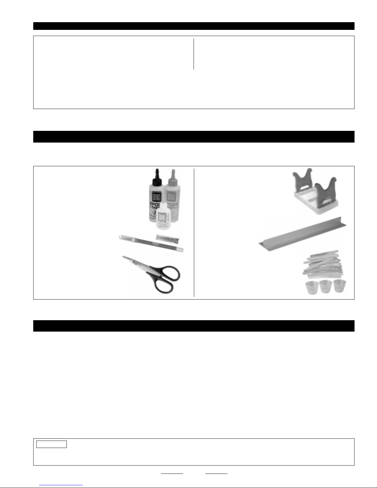
❑ Kwik Bond Thin C/A # 887500
❑ Kwik Bond Thick C/A # 887510
❑ Kwik Bond 5 Minute Epoxy # 887560
❑ Kwik Bond 30 Minute Epoxy # 887565
❑ Kwik Bond C/A Debonder # 887545
❑ Wilhold Silicon Sealant # 335407
❑ #1 & #2 Phillips Head Screwdrivers
❑ 2.5mm Hex Wrench
❑ Wire Cutters
❑ Needle Nose Pliers
❑ Adjustable Wrench
❑ Excel Modeling Knife # 692801
❑ Scissors
❑ Electric Drill
❑ Assorted Drill Bits
❑ Ernst Airplane Stand # 223977
❑ Ruler
❑ Pencil
❑ Dubro T-Pins # 567677
❑ Builder's Triangle
❑ 220 Grit Sandpaper w/Sanding Block
❑ Masking Tape
❑ Paper Towels
❑ Wax Paper
❑ Petroleum Jelly
❑ Rubbing Alcohol
❑ NHP Epoxy Mixing Sticks # 864204
❑ NHP Epoxy Mixing Cups # 864205
❑ Global Heat Gun # 360920
❑ Global Heat-Sealing Iron # 360900
SECTION 3: A NOTE ABOUT COVERING
The covering material used on the Clancy Aviation Speedy Bee ARF is real iron-on, heat-shrink covering material. It is possible with
heat and humidity changes that the covering on your airplane may wrinkle or sag. This trait is inherent in all types of heat-shrink
material. To remove any wrinkles that might be visible you will need to use a heat-sealing covering iron.
Follow this simple procedure to remove the wrinkles:
❑ Plug in and turn on the sealing iron to the medium-high temperature setting. Allow the sealing iron to heat up for approximately
5 - 7 minutes.
❑ After the sealing iron has reached temperature, lightly apply the sealing iron to the wrinkled section of the covering. Move the
sealing iron slowly over the wrinkled section until the covering tightens and the wrinkles disappear.
If the color layer smears from any of the seams the temperature of the sealing iron is too hot. Turn the temperature dial down
☞
and wait about 5 minutes for the sealing iron to adjust to the lower temperature. You can remove any excess color streaks using a
paper towel soaked with a small quantity of Acetone.
PRO TIP
for any length of time. The extreme heat could cause the covering material to wrinkle and possibly damage the fragile components
of the radio control system.
We do not suggest storing your airplane in an extremely hot environment (like the back of your car in direct sunlight)
5
Page 6
SECTION 4: KIT CONTENTS
We have organized the parts as they come out of the box for easier identification during assembly. Before you begin assembly,
group the parts as we list them below. This will ensure that you have all of the parts before you begin assembly and it will also help
you become familiar with each part.
If you find any parts missing or damaged, please contact us as soon as possible, using the Customer Service
Information on page # 3.
A complete replacement parts list can be found on page # 37.
AIRFRAME ASSEMBLIES
❑ (1) Fuselage
❑ (1) Center Wing Panel
❑ (1) Left Wing Tip Panel w/Aileron
❑ (1) Right Wing Tip Panel w/Aileron
❑ (1) Horizontal Stabilizer w/Elevator
❑ (1) Rudder
LANDING GEAR ASSEMBLY
❑ (1) Steel Axle
❑ (1) Aluminum Tube
❑ (2) Main Gear Wheels
❑ (2) Nylon Spacers
❑ (2) Wheel Collars
❑ (2) M3 x 6mm Machine Screws
❑ (2) Rubber Bands
AILERON CONTROL SYSTEM
❑ (2) 3-3/8" Threaded Wires w/Z-Bends
❑ (2) Nylon Control Horns
❑ (2) Nylon Clevises
❑ (4) M2 x 10mm Wood Screws
❑ (8) Nylon Steel-Pinned Hinges
RUDDER CONTROL SYSTEM
❑ (1) 6-1/8" Threaded Wire w/Z-Bend
❑ (1) Nylon Control Horn w/Backplate
❑ (1) Nylon Clevis
❑ (2) M2 x 12mm Machine Screws
❑ (1) C/A-Style Hinge
TAIL WHEEL ASSEMBLY
❑ (1) Prebent Tail Wheel Wire w/Nylon Bearing
❑ (1) Tail Wheel
❑ (1) Nylon Spacer
❑ (1) Wheel Collar
❑ (1) M3 x 5mm Machine Screw
FUEL TANK ASSEMBLY
❑ (1) 85cc Fuel Tank
❑ (1) Large Diameter Metal Plate
❑ (1) Small Diameter Metal Plate
❑ (1) Neck-Reinforcement Ring
❑ (1) Rubber Stopper
❑ (1) Fuel Pick-Up "Clunk"
❑ (1) M3 x 20mm Machine Screw
❑ (1) Silicone Fuel Tubing
❑ (3) Aluminum Tubing
ELEVATOR CONTROL SYSTEM
❑ (1) 5-1/2" Threaded Wire w/Z-Bend
❑ (1) Nylon Control Horn w/Backplate
❑ (1) Nylon Clevis
❑ (2) M2 x 12mm Machine Screws
❑ (6) C/A-Style Hinges
ENGINE MOUNT ASSEMBLY
❑ (2) Engine Mounting Beams
❑ (4) M3 x 18mm Machine Screws
❑ (4) M3 x 25mm Socket-Cap Screws
❑ (4) M3 Lock Nuts
❑ (4) M3 Blind Nuts
❑ (12) M3 Flat Washers
THROTTLE CONTROL SYSTEM
❑ (1) 11-3/4" Plain Wire w/Z-Bend
❑ (1) Adjustable Pushrod Connector w/Machine Screw & Nut
OPTIONAL ELECTRIC MOTOR MOUNT ASSEMBLY
❑ (4) Motor Mounting Straps
❑ (4) M3 x 12mm Wood Screws
❑ (4) M3 Flat Washers
MISCELLANEOUS FUSELAGE PARTS
❑ (2) Hardwood Dowels
❑ (2) Plywood Mounting Plates (Optional)
❑ (1) Plastic Windscreen
❑ (5) M2 x 5mm Wood Screws
❑ (2) M2 x 10mm Flange-Head Wood Screws
❑ (1) Clear Vinyl Tubing
❑ (1) Decal Set
MISCELLANEOUS WING PARTS
❑ (1) Front Wing Deck
❑ (1) Rear Wing Deck
❑ (4) Plywood Rubber Band Doublers
6
Page 7

SECTION 5: LITHIUM POLYMER BATTERY WARNINGS - PLEASE READ
If you will be powering your Speedy Bee ARF with an electric motor and are using a lithium polymer flight
battery, please read and understand the warnings listed in this section. Also make sure to read any and all
warnings included in the packaging with your battery. If used improperly, lithium polymer batteries can be very
dangerous, so please follow these warnings and suggestions at all times.
WARNINGS AND SAFETY PRECAUTIONS FOR ALL BRANDS OF LITHIUM POLYMER BATTERIES
●
This product may explode or catch fire. Serious injury can result from misuse. Serious injury, loss of property, fire and death
can result from misuse of this product.
●
All instructions, warnings and cautions must be followed at all times. Failure to do so can lead to serious injury or fire.
●
Do NOT use this product before reading and understanding all directions and warnings.
●
Do NOT overcharge. Maximum voltage for each pack must be followed.
●
Do NOT over-discharge. NEVER discharge below minimum volts.
●
Do NOT discharge at a rate greater than the maximum continuous discharge.
●
Do NOT use or charge if the battery is hot.
●
ONLY use a charger made for Lithium Polymer batteries.
●
Do NOT charge at a rate higher than 1C. Example: if the battery’s rating is 340mAH, then the charger’s charge rate must be set
at 340mAH or less.
●
Do NOT leave in direct sunlight or in a hot car or storage area.
●
Do NOT get wet or expose to moisture.
You MUST use a LiPO-compatible
charger, like the WattAge Charge-It-All,
to charge LiPO batteries
●
Do NOT short-circuit the battery.
●
ONLY discharge and charge the battery outdoors or in a fire-safe container.
●
Do NOT charge with reverse polarity.
●
Do NOT leave the battery connected when not in use.
●
Do NOT operate or charge unattended.
●
Do NOT solder to the battery directly and do not get the battery hot in any way.
P/N 130116
CHARGING PRECAUTIONS FOR ALL BRANDS OF LITHIUM POLYMER BATTERIES
●
Do NOT use the product if you do not understand the warnings and proper use of the product.
●
Always let the battery cool and "rest" between uses and charging.
●
To avoid over-discharging, only use a speed control that is made for LiPO batteries.
●
We recommend the use of a fire-safe container when charging or storing.
●
Do NOT charge inside your car or inside your house.
●
Inspect the battery before each use for swelling or other malformation. If the cell has ballooned, it MUST be discarded.
●
Set the charger to 1C (charge at 1/2C or less for the first 5 cycles).
●
Check polarity and then connect battery to charger.
●
In use, do not to over-discharge or exceed maximum discharge.
●
When handling the battery, remember not to poke, bend or damage the cell. The cell outer casing is soft and can be damaged.
●
Remember, the cells must never exceed 160 degrees Fahrenheit for any reason.
7
Page 8
SECTION 6: WING ASSEMBLY
YOU'LL NEED THE FOLLOWING PARTS FROM THE KIT:
❑ (1) Center Wing Panel
❑ (1) Left Wing Tip Panel w/Aileron
YOU'LL NEED THE FOLLOWING TOOLS AND SUPPLIES:
❑ Kwik Bond 30 Minute Epoxy
❑ # 1 Phillips Head Screwdriver
❑ Excel Modeling Knife
❑ Electric Drill
❑ 1/16" Drill Bit
❑ Ruler
STEP 1: ALIGNING THE WING TIP PANELS
❑ Remove the aileron and hinges from both wing tip panels and set them aside.
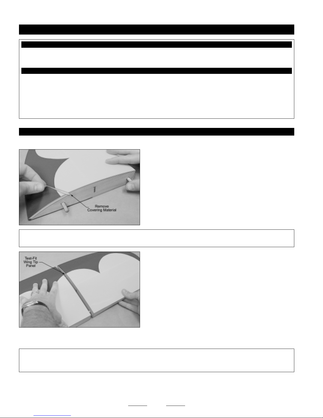
❑ Using a modeling knife, cut away and remove the excess covering
material that overlaps onto the root ribs of each wing tip panel, leaving
about 1/16" overlapped so it does not pull away.
❑ Repeat the previous procedure to remove the covering material from
both ends of the center wing panel.
❑ (1) Right Wing Tip Panel w/Aileron
❑ Masking Tape
❑ Paper Towels
❑ Rubbing Alcohol
❑ NHP Epoxy Mixing Sticks
❑ NHP Epoxy Mixing Cups
❑ Global Heat Gun
✦✦
✦IMPORTANT
✦✦
ribs and the ends of the center wing panel as possible. Do not omit this procedure or the wing joints may fail during flight.
❑ While holding the two wing panels together firmly, make sure that the wing panels are lined up at both the leading and trailing
edges, then look carefully at the glue joint: the wing panels should fit together tightly with few or no gaps in the joint.
✦✦
✦IMPORTANT
✦✦
the root rib of the wing tip panel and/or the end of the center wing panel, until you are satisfied with the fit. Remember, when the
wing panels are pushed together, there should be few or no gaps in the glue joint.
❑ Repeat the previous procedures to align and test-fit the other wing tip panel to the center wing panel.
✦✦
✦ It's very important to the integrity of the glue joints that you remove as much covering material from the root
✦✦
❑ Working with one wing tip panel for now, carefully test-fit the wing tip
panel onto the corresponding end of the center wing panel (without
using glue), making sure that the dowels in the wing tip panel engage
the holes in the center wing panel.
✦✦
✦ If the wing panels do not fit together properly, use 220 grit sandpaper with a sanding block to lightly sand
✦✦
❑ When satisfied with the fit and alignment, remove the wing tip panels from the center wing panel and set them aside.
8
Continued On Next Page
☛☛
☛
☛☛
Page 9
STEP 2: JOINING THE WING PANELS
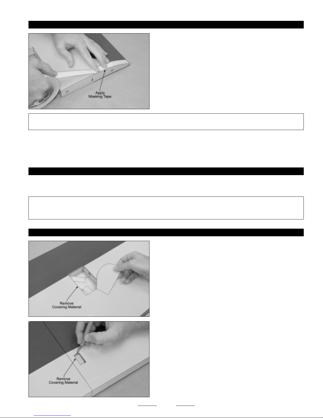
❑ Apply a strip of masking tape to the top and bottom edges of the root
rib on one wing tip panel and the top and bottom edges of the
corresponding end of the center wing panel.
The masking tape will prevent excess epoxy from getting onto the
☞
wing panels when you join them.
❑ Mix a generous amount of 30 minute epoxy and apply a thin layer to
the entire surface of BOTH root ribs, the two dowels in the wing tip
panel and into the holes in the center wing panel. Make sure to use
enough epoxy to fill any gaps.
✦✦
✦IMPORTANT
✦✦
root ribs and the two dowels. Not using enough epoxy can result in wing failure during flight.
❑ Slide the two wing panels together and realign them. Quickly wipe away any excess epoxy, using a paper towel and rubbing
alcohol, and use pieces of masking tape to hold the two wing panels aligned until the epoxy fully cures.
❑ After the epoxy fully cures, repeat the previous procedures to glue the second wing tip panel to the center wing panel.
STEP 3: CHECKING THE GLUE JOINTS
❑ Once the epoxy has fully cured, remove the masking tape and double-check both glue joints. If any gaps are present, mix a
small quantity of 30 minute epoxy and carefully fill any remaining gaps.
✦✦
✦IMPORTANT
✦✦
gaps that appear in the glue joints after the epoxy has cured. To make the glue joints as strong as possible, it's important to fill any
gaps, using 30 minute epoxy.
STEP 4: INSTALLING THE AILERON SERVOS
✦✦
✦ It is of the utmost importance to the integrity of the glue joint that you apply a generous amount of epoxy to both
✦✦
✦✦
✦ Do not omit this procedure. All three wing panels should fit together tightly, but it's possible to have some small
✦✦
❑ Using a modeling knife, cut away and remove the covering material
from over the aileron servo lead exit hole in the bottom of the wing. The
center of the hole is 7-1/2" in front of the trailing edge and the hole is
2-3/8" wide and 3-3/4" long.
❑ Using a modeling knife, cut away and remove the covering material
from over the two aileron servo mounting holes in the bottom of the
wing. The holes are located 1/2" in from the wing tip panel glue joints
and 3" in front of the trailing edge.
9
Continued On Next Page
☛☛
☛
☛☛
Page 10
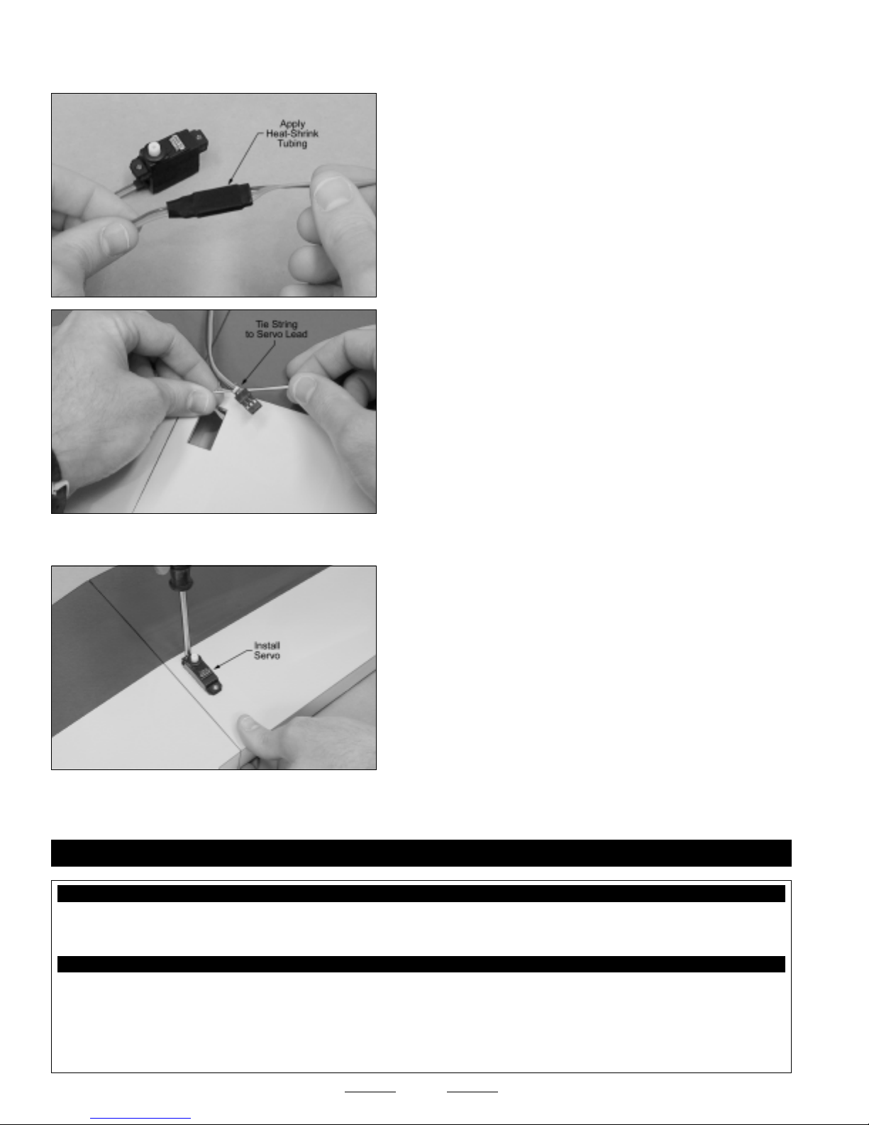
❑ Install the rubber grommets and brass collets onto one aileron servo, making sure to install the collets with the flanges toward
the bottom of the servo.
❑ Plug one 12" servo extension onto the aileron servo lead.
❑ To prevent the plugs from pulling apart during assembly, or worse,
during flight, secure the plugs together, using a short piece of 3/8"
diameter heat-shrink tubing. Use a heat gun to shrink the tubing tight.
❑ Tie the end of the length of preinstalled string in the servo mounting
hole to the servo lead plug and use it to pull the servo lead through
the wing.
Tie the end of the string to the servo lead plug at the servo mounting hole, then pull the string from the other end to guide the
☞
servo lead out through the bottom of the wing.
❑ Set the servo into place, making sure that the servo output shaft is
toward the leading edge of the wing.
❑ Install the aileron servo, making sure to drill 1/16" diameter pilot holes
for the mounting screws.
The servo hole is sized to fit most standard-size mini servos. You
☞
may need to enlarge the hole slightly to fit your particular servo.
❑ Repeat the previous procedures to install the second aileron servo into the wing.
SECTION 7: WING MOUNTING
YOU'LL NEED THE FOLLOWING PARTS FROM THE KIT:
❑ (1) Fuselage
❑ (2) Hardwood Dowels
❑ (4) Plywood Rubber Band Doublers
YOU'LL NEED THE FOLLOWING TOOLS AND SUPPLIES:
❑ Kwik Bond Thick C/A
❑ Kwik Bond 5 Minute Epoxy
❑ Excel Modeling Knife
❑ Ruler
❑ Pencil
❑ Masking Tape
❑ Paper Towels
❑ Rubbing Alcohol
❑ NHP Epoxy Mixing Sticks
❑ NHP Epoxy Mixing Cups
10
Continued On Next Page
☛☛
☛
☛☛
Page 11
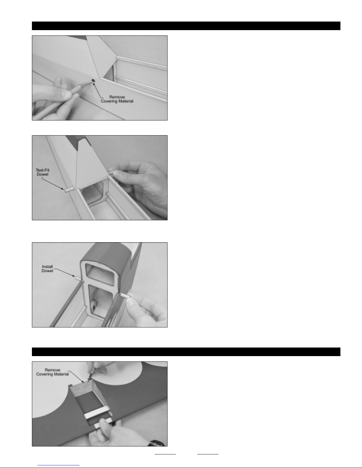
STEP 1: INSTALLING THE WING HOLD-DOWN DOWELS
❑ Using a modeling knife, cut away and remove the covering material
from over the two precut wing hold-down dowel mounting holes behind
the wing saddle.
One hole is located on each side of the fuselage, 5/16" below and 3/8" behind the wind saddle.
☞
❑ Test-fit one hardwood dowel into the fuselage. When aligned
properly, the dowel should be centered, so that the ends of the dowel
are equal distance from the fuselage sides.
❑ When satisfied with the fit, glue the dowel into place, using a thin layer of 5 minute epoxy. Remove any excess epoxy, using a
paper towel and rubbing alcohol.
❑ Repeat the previous procedures to install the second hardwood dowel
into the precut holes in front of the wing saddle.
One hole is located on each side of the fuselage, 1/2" below and 1/4" in front of the wind saddle.
☞
STEP 2: INSTALLING THE RUBBER BAND DOUBLERS
❑ Using a modeling knife, cut away and remove the covering material
from over the fuel tank support hatch in the top of the wing. The hatch
is 2-3/8" wide and 4-1/4" long.
11
Continued On Next Page
☛☛
☛
☛☛
Page 12
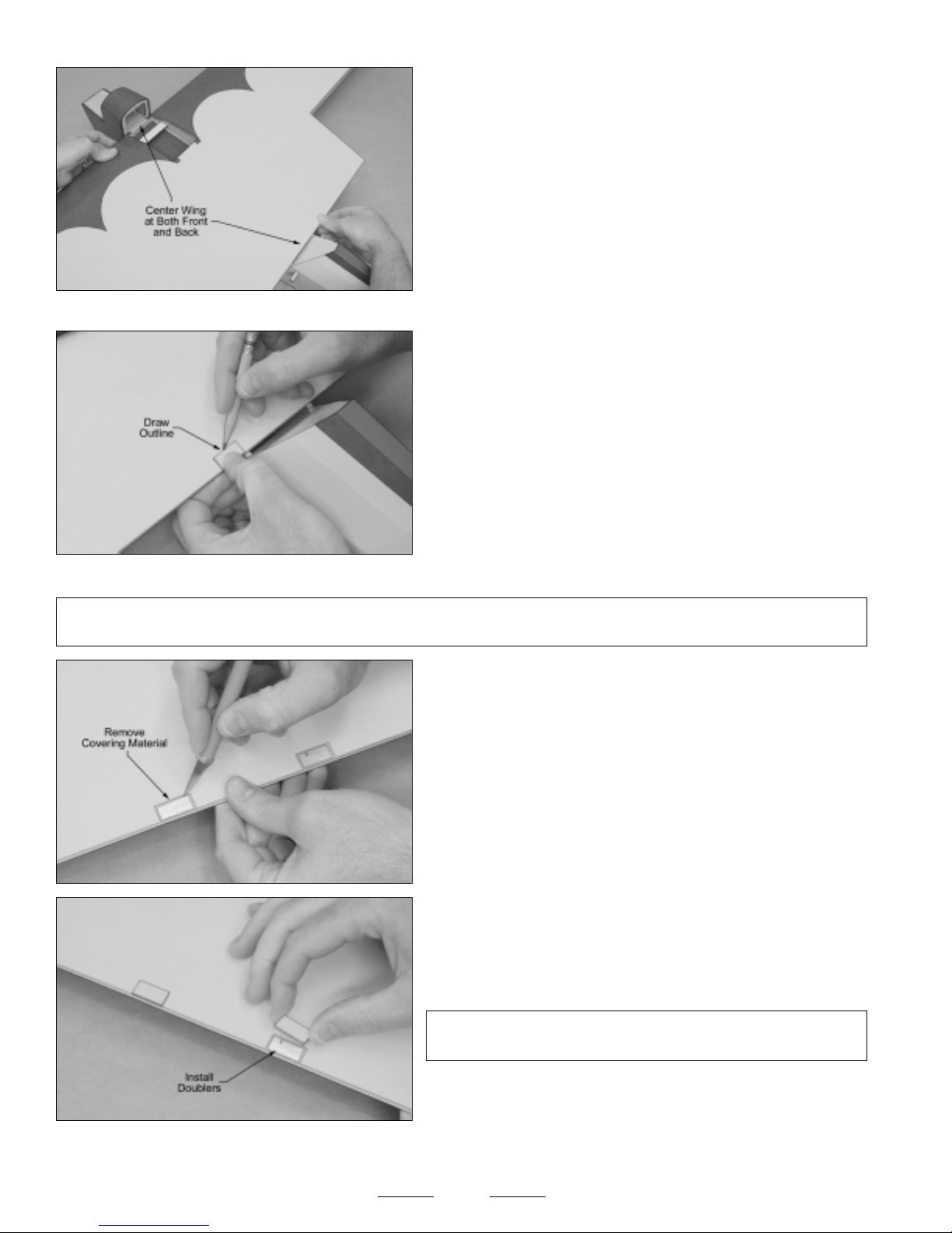
❑ Set the wing into the wing saddle and carefully center it at both the
leading and trailing edges.
Push the wing as far forward as possible. There will be a narrow
☞
gap between the trailing edge and the fuselage. This is normal and will
be filled by the rear wing deck.
❑ When satisfied with the alignment, hold the wing firmly in place, using a couple of weights.
❑ With the wing held firmly in place, position the two rear rubber band
doublers onto the top of the wing and align them. When aligned
properly, the back edge of the doublers should be even with the trailing
edge and the inside edge of the doublers should be even with or slightly
out from the sides of the fuselage.
❑ When satisfied with the alignment, use a pencil to carefully trace an
outline around the two doublers onto the wing.
The two rear rubber band doublers are precovered in yellow to match the wing.
☞
✦✦
✦IMPORTANT
✦✦
fuselage. This will ensure that the doublers will not interfere with the installation of the rear wing deck.
✦✦
✦ It's important to make sure that the inside edge of each doubler is even with or slightly out from the sides of the
✦✦
❑ Remove the wing from the fuselage and use a modeling knife to
cut away and remove the covering material from within the outlines
you drew.
❑ Using thick C/A, carefully glue the two rubber band doublers to the
wing. Allow the C/A to fully cure before proceeding.
✦✦
✦IMPORTANT
✦✦
removed promptly using a paper towel and C/A debonder.
✦✦
✦ If any excess C/A gets onto the wing, it can be
✦✦
❑ Set the wing back into the wing saddle and realign it. Double-check to make sure that it's centered at both the leading and
trailing edges. Again, use a couple of weights to hold the wing firmly in place.
12
Continued On Next Page
☛☛
☛
☛☛
Page 13
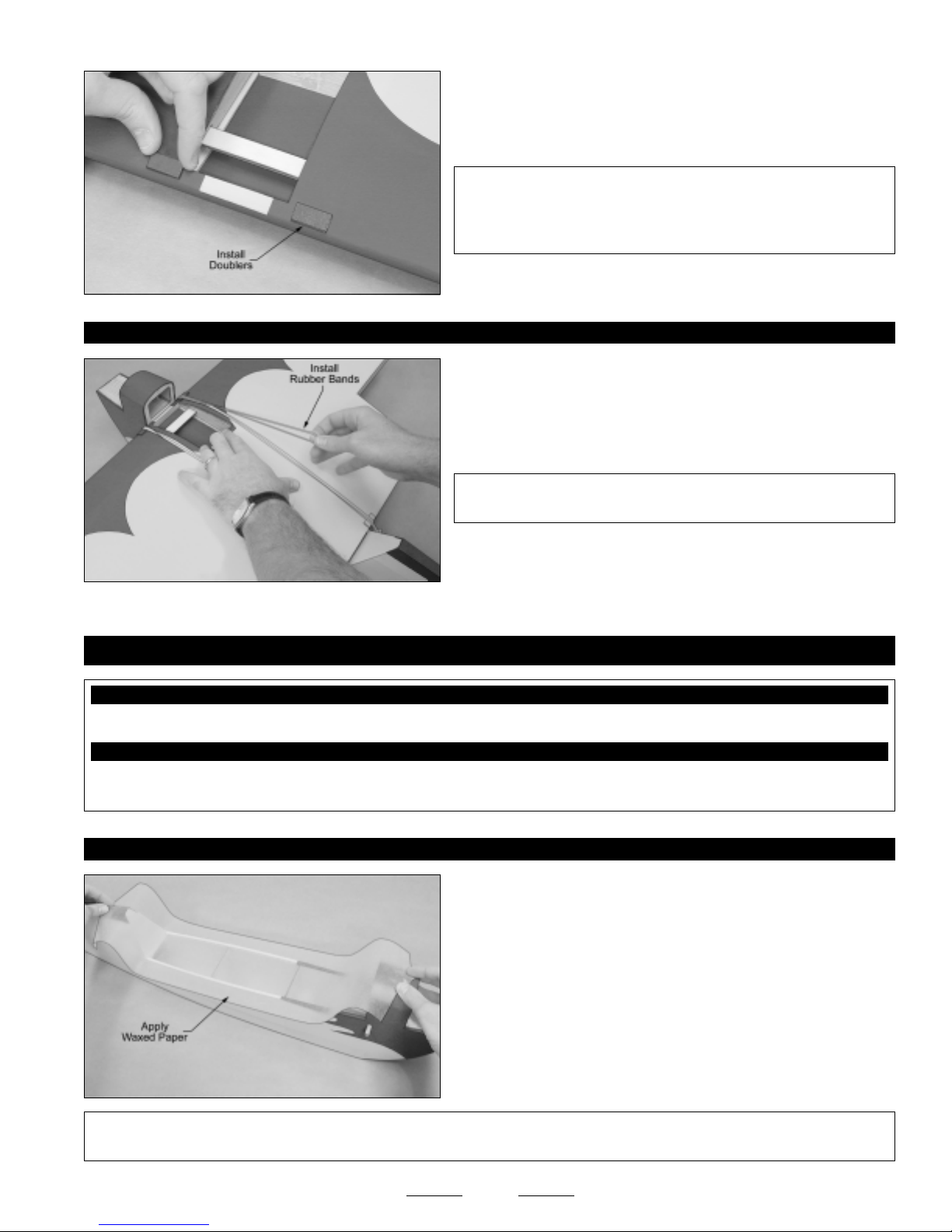
❑ Repeat the previous procedures to install the two remaining rubber
band doublers onto the front of the wing.
STEP 3: INSTALLING THE WING
✦✦
✦IMPORTANT
✦✦
the doublers be even with or slightly out from the fuselage sides. This
will ensure that the doublers will not interfere with the installation of
the front wing deck.
❑ Set the wing back into the wing saddle and realign it. Use two # 64
rubber bands per side to secure the wing into place.
✦✦
✦IMPORTANT
✦✦
minimum of six # 64 rubber bands per side.
✦✦
✦ Remember, it's important that the inside edge of
✦✦
✦✦
✦ For flight you should hold the wing in place using a
✦✦
SECTION 8: WING DECK INSTALLATION
YOU'LL NEED THE FOLLOWING PARTS FROM THE KIT:
❑ (1) Front Wing Deck
YOU'LL NEED THE FOLLOWING TOOLS AND SUPPLIES:
❑ Wilhold Silicon Sealant
❑ Masking Tape
STEP 1: INSTALLING THE FRONT WING DECK
❑ (1) Rear Wing Deck
❑ Paper Towels
❑ Wax Paper
❑ Remove the wing, lay a long piece of wax paper over the wing saddle,
then reinstall the wing, making sure that the ends of the wax paper are
covering the joints between the fuselage and the leading and trailing
edges of the wing.
✦✦
✦IMPORTANT
✦✦
ensure that you don't accidentally glue the wing to the fuselage when you glue the wing decks into place.
✦✦
✦ It's important to use wax paper or plastic wrap when you glue the wing decks to the wing. The wax paper will
✦✦
13
Continued On Next Page
☛☛
☛
☛☛
Page 14
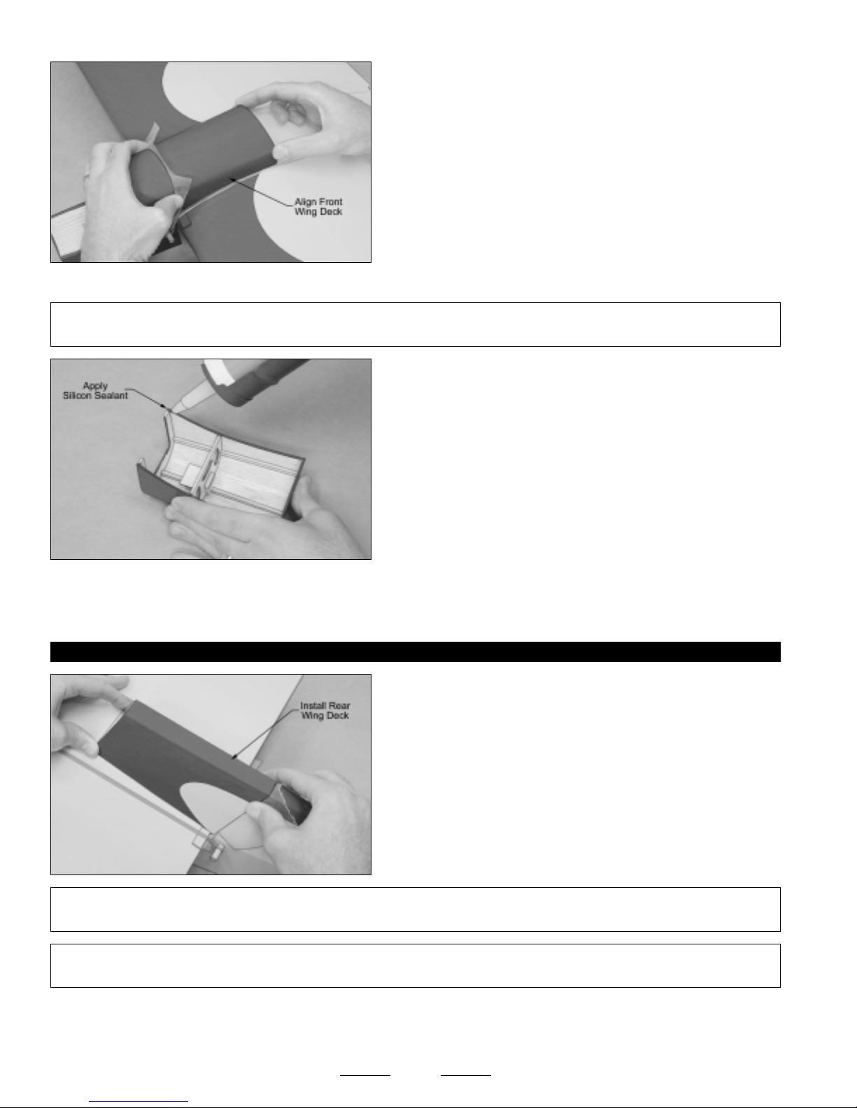
❑ Install the wing, making sure that it's centered and pushed as far
forward as possible. Position the front wing deck onto the wing. When
lined up properly, the sides and top of the wing deck should be even
with the sides and top of the fuselage, and there should be few or no
gaps between the base of the wing deck and the wing.
Some small gaps between the base of the wing deck and the wing
☞
are normal. They will be filled with silicon when the wing deck is glued
into place.
You may need to spread the rubber bands out slightly, so that they don't interfere with the installation of the wing deck.
☞
✦✦
✦IMPORTANT
✦✦
front of the wing deck.
❑ Set the front wing deck back into place and realign it. When satisfied with the alignment, push the wing deck down firmly
and remove any excess silicon sealant, using a paper towel and water. Hold the wing deck securely in place, using pieces of
masking tape.
STEP 2: INSTALLING THE REAR WING DECK
✦✦
✦ So that the wing can be installed and removed, there should be a narrow gap between the fuselage and the
✦✦
❑ Apply a generous bead of silicon sealant to the base of the front
wing deck, making sure that you cover all of the gluing surfaces. This
includes not only the sides of the wing deck, but the front and back, too.
Make sure to use enough silicon sealant to fill any small gaps or
☞
irregularities in the glue joint.
❑ Use the same procedures in the previous step to align and install the
rear wing deck. When lined up properly, the sides and top of the wing
deck should be even with the sides and top of the fuselage, and there
should be few or no gaps between the base of the wing deck and
the wing.
✦✦
✦IMPORTANT
✦✦
back of the wing deck.
✦✦
✦IMPORTANT
✦✦
time. You must allow sufficient time for the silicon sealant to dry.
❑ After the silicon sealant has fully cured, look carefully at the glue joints between the front and rear wing decks and the wing. If
there are any gaps in the glue joints, carefully fill them using extra silicon sealant, making sure to remove any excess before it cures,
using a paper towel and water. This will ensure the strongest possible bond.
✦✦
✦ So that the wing can be installed and removed, there should be a narrow gap between the fuselage and the
✦✦
✦✦
✦ It will take the silicon sealant about 24 hours to fully cure. We suggest not moving the assembly during this
✦✦
Notice that the back edge of the rear wing deck overlaps the trailing
☞
edge of the wing.
14
Page 15
SECTION 9: HORIZONTAL STABILIZER INSTALLATION
YOU'LL NEED THE FOLLOWING PARTS FROM THE KIT:
❑ (1) Horizontal Stabilizer w/Elevator
YOU'LL NEED THE FOLLOWING TOOLS AND SUPPLIES:
❑ Kwik Bond 30 Minute Epoxy
❑ Excel Modeling Knife
❑ Ruler
❑ Pencil
❑ Dubro T-Pins
STEP 1: ALIGNING THE HORIZONTAL STABILIZER
❑ Remove the elevator and hinges from the horizontal stabilizer and set them aside for now.
❑ Using a modeling knife, cut away and remove the covering material
from over the horizontal stabilizer mounting slot in each side of the
fuselage. The slot is 5" long and 1/4" wide.
❑ 220 Grit Sandpaper w/Sanding Block
❑ Paper Towels
❑ Rubbing Alcohol
❑ NHP Epoxy Mixing Sticks
❑ NHP Epoxy Mixing Cups
✦✦
✦IMPORTANT
✦✦
aligned. The trailing edge should not be allowed to move from side to side.
✦✦
✦ The front of the stabilizer should be able to pivot from side to side and the back should stay firmly in place and
✦✦
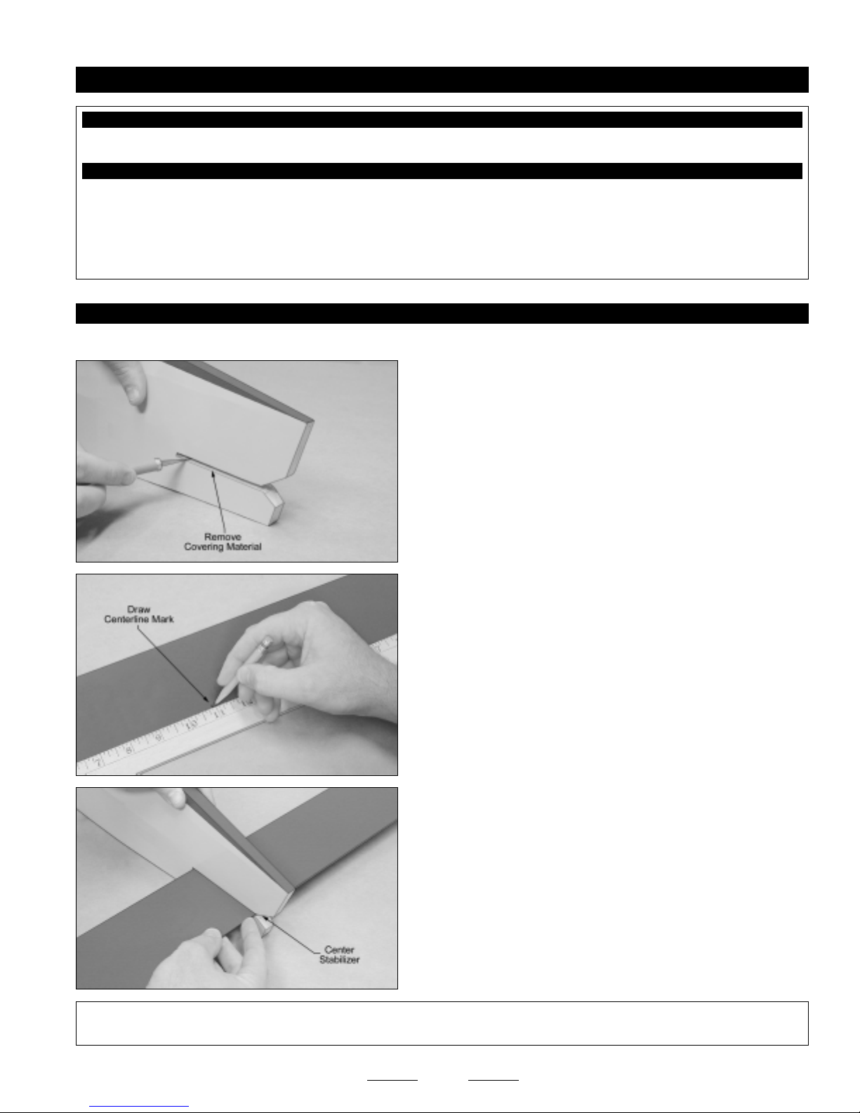
❑ Using a ruler and a pencil, locate and draw a centerline mark on the
trailing edge of the stabilizer.
❑ Slide the stabilizer into the mounting slot and temporarily align it.
The stabilizer should be pushed forward as far as possible and the
centerline mark you drew on the stabilizer should be lined up with the
centerline of the fuselage.
❑ When satisfied with the alignment, hold only the trailing edge of the
stabilizer in position using a T-Pin.
15
Continued On Next Page
☛☛
☛
☛☛
Page 16
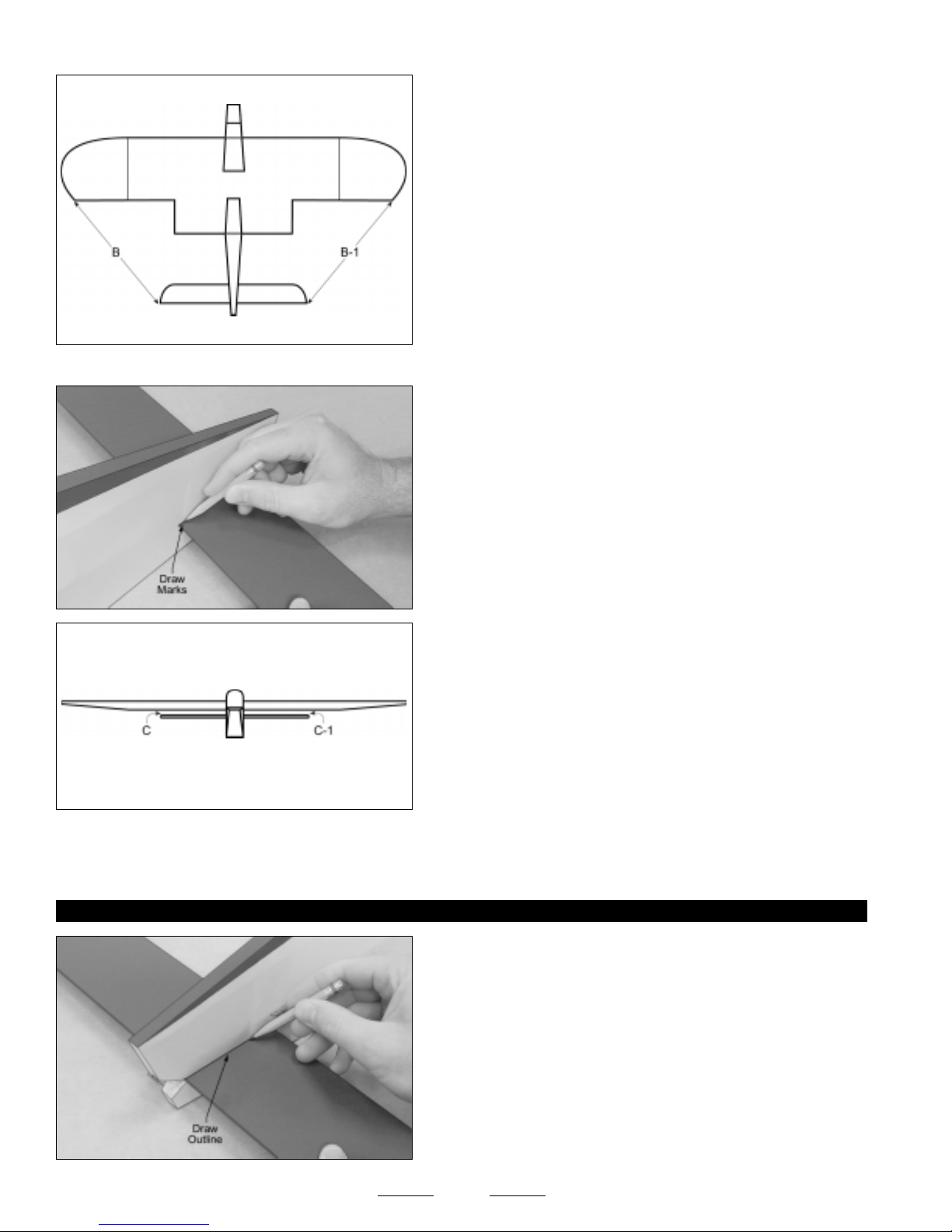
❑ With the wing mounted to the fuselage, use a ruler to measure the
distance between the tips of the stabilizer and the tips of the wing. Pivot
the front of the stabilizer until both of these measurements are equal.
B=B-1
When both of these measurements are equal, you're assured that the stabilizer is square to the wing.
☞
❑ When you're satisfied that the stabilizer is square to the wing, use a
pencil to draw a mark on each side of the front of the stabilizer where
it and the fuselage sides meet, then use a T-Pin to hold the stabilizer
firmly in place and aligned.
❑ With the stabilizer held firmly in place, look from the front of the
airplane at both the wing and the stabilizer. When aligned properly, the
stabilizer should be parallel to the wing.
C=C-1
If the stabilizer is not parallel to the wing, remove it and use 220 grit sandpaper with a sanding block to sand down the higher
☞
side of the stabilizer mounting slot, then reinstall the stabilizer and check the alignment once more. Repeat this procedure until
you are satisfied with the alignment.
STEP 2: MOUNTING THE HORIZONTAL STABILIZER
❑ When satisfied with the alignment, use a pencil to draw a line on
each side of the stabilizer where it meets the fuselage sides. Do this on
both the top and the bottom.
16
Continued On Next Page
☛☛
☛
☛☛
Page 17
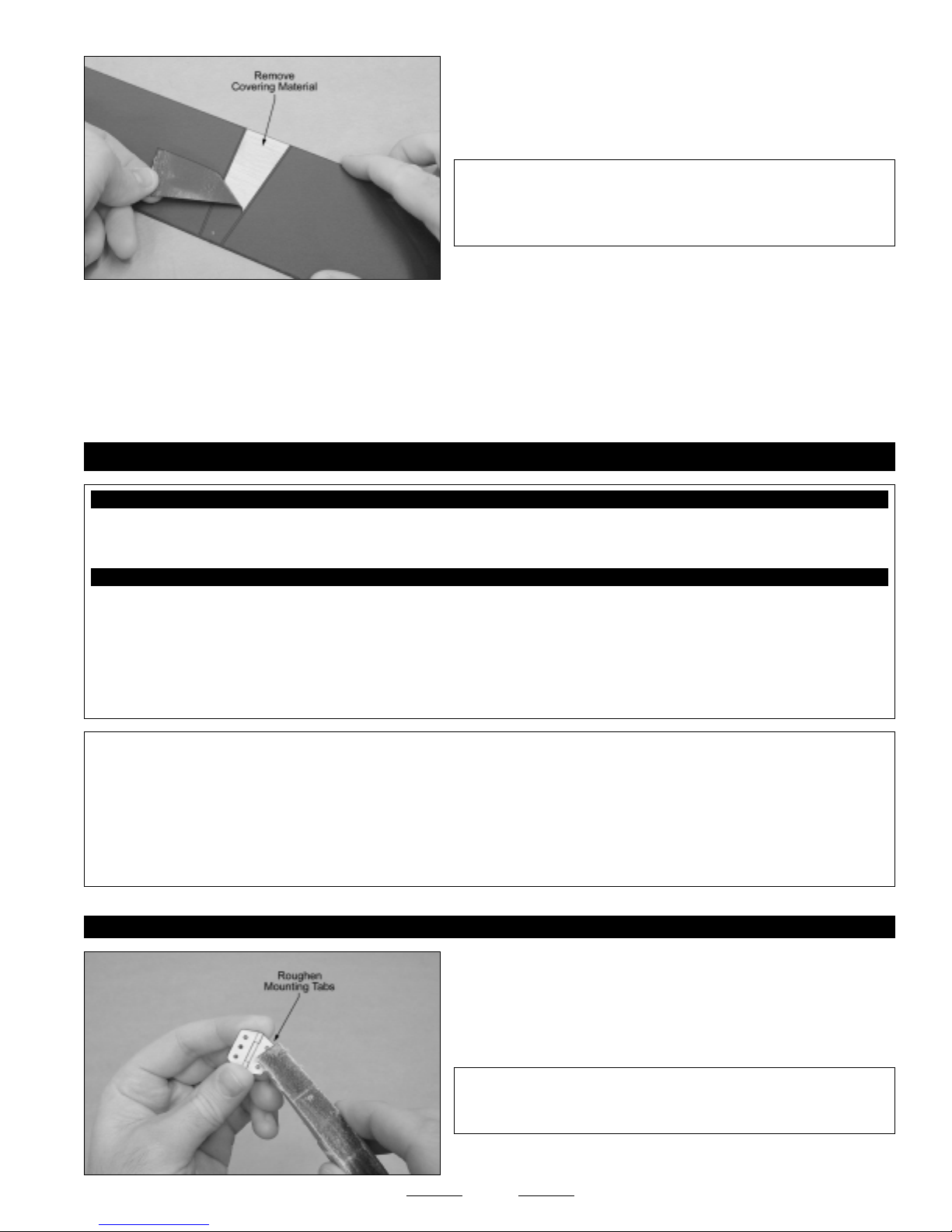
❑ Remove the stabilizer from the fuselage and use a modeling knife to
carefully cut away and remove the covering material from between the
lines you drew. Do this on both the top and the bottom.
✦✦
✦WARNING
✦✦
with only enough pressure to cut through only the covering itself.
Cutting down into the balsa structure could weaken the stabilizer and
cause it to fail during flight.
❑ Mix a generous amount of 30 minute epoxy and carefully apply a thin layer to the top and bottom of the gluing surfaces of the
stabilizer, and to the gluing surfaces of the stabilizer mounting slot.
❑ Slide the stabilizer back into place and realign it, double-checking all of your measurements once more before the epoxy
sets up. Quickly remove any excess epoxy, using a paper towel and rubbing alcohol, and use T-Pins to hold the stabilizer in place
and aligned until the epoxy has fully cured.
✦✦
✦ When cutting through the covering to remove it, cut
✦✦
SECTION 10: CONTROL SURFACE HINGING
YOU'LL NEED THE FOLLOWING PARTS FROM THE KIT:
❑ (1) Rudder
❑ (8) Nylon Steel-Pinned Hinges
YOU'LL NEED THE FOLLOWING TOOLS AND SUPPLIES:
❑ Kwik Bond Thin C/A
❑ Kwik Bond 5 Minute Epoxy
❑ Kwik Bond C/A Debonder
❑ Excel Modeling Knife
❑ Dubro T-Pins
❑ 220 Grit Sandpaper w/Sanding Block
❑ (7) C/A-Style Hinges
❑ (1) Prebent Tail Wheel Wire w/Nylon Bearing
❑ Paper Towels
❑ Rubbing Alcohol
❑ Petroleum Jelly
❑ NHP Epoxy Mixing Sticks
❑ NHP Epoxy Mixing Cups
✦✦
✦Important Information About the Hinges Included with Your Speedy Bee ARF
✦✦
The hinges are not glued into place from the factory. You must glue them into place. The ailerons are hinged using plastic steelpinned hinges that are designed to be glued into place with epoxy. Do not use thin C/A to glue these hinges into place. The
elevator and rudder are hinged using C/A-style hinges. These hinges are designed to be glued into place using thin C/A. Do not
glue these hinges into place using any other type of glue, such as thick C/A or epoxy.
For flutter-free control surfaces and crisp control response, it is imperative that the hinges be glued in properly. This is achieved
by having a tight hinge gap (no more than 1/32" wide) and using plenty of glue.
STEP 1: HINGING THE AILERONS
✦✦
✦
✦✦
❑ Using 220 grit sandpaper with a sanding block, lightly sand both sides
of the mounting tabs on each of the eight hinges, to roughen the smooth,
plastic surfaces.
✦✦
✦IMPORTANT
✦✦
stick to it. If you don't roughen the plastic, the hinge(s) may pull out
during flight.
17
✦✦
✦ You must roughen the plastic so that the epoxy will
✦✦
Continued On Next Page
☛☛
☛
☛☛
Page 18
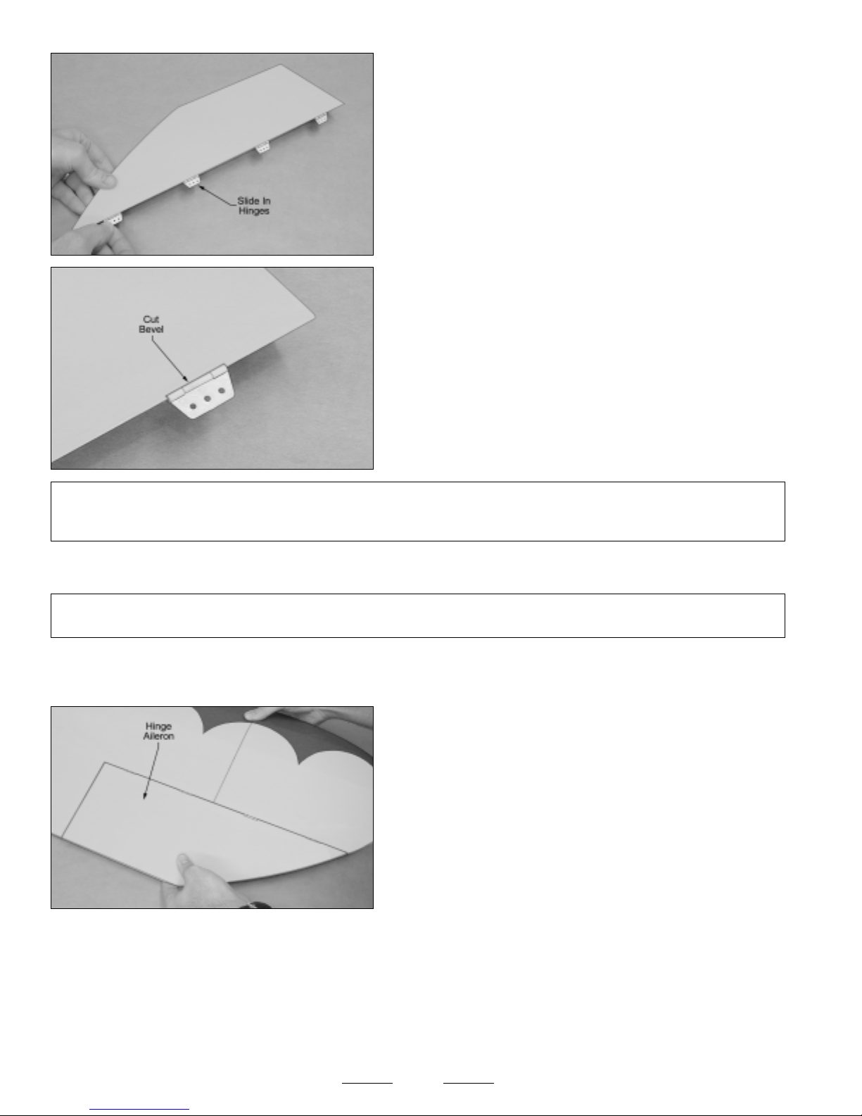
❑ Slide four of the hinges into one aileron and center them in the middle
of the hinge slots.
❑ Using a modeling knife, carefully cut a shallow bevel in the aileron
directly above and below each hinge, so that the hinge pivot point can
be recessed into the leading edge.
✦✦
✦IMPORTANT
✦✦
be flush with the leading edge of the aileron. This will ensure that there will be little to no hinge gap when the aileron is hinged
to the wing.
❑ When satisfied with the fit and alignment, remove the hinges and carefully apply a thin coat of lightweight oil or petroleum jelly to
only the pivot point of each of the four hinges.
✦✦
✦IMPORTANT
✦✦
from being glued solid when you install them.
❑ Mix a small quantity of 5 minute epoxy and carefully glue each of the four hinges into only the aileron for now. Make sure that the
hinges' pivot points are straight and flush with the leading edge of the aileron, then remove any excess epoxy, using a paper towel
and rubbing alcohol. Allow the epoxy to set up for about 10 minutes before proceeding.
✦✦
✦ The bevel should be deep enough so that when you push the hinge in further, the pivot point of the hinge will
✦✦
✦✦
✦ Do not omit this procedure. Applying lightweight oil or petroleum jelly to the pivot point will prevent the hinges
✦✦
❑ After the epoxy has set up, test-fit the aileron to the wing panel,
making sure that the leading edge of the aileron is pushed firmly up
against the trailing edge of the wing panel, and that the tip of the aileron
is even with the tip of the wing. There should be no more than a 1/32"
wide hinge gap.
If you can't push the aileron far enough forward to achieve the proper
☞
hinge gap, you will need to cut a shallow bevel in the trailing edge of the
wing for each of the hinges.
❑ When satisfied with the fit, remove the aileron and apply another coat of lightweight oil or petroleum jelly to each hinge pivot
point, then hinge the aileron to the wing, using 5 minute epoxy. Remove any excess epoxy, using a paper towel and rubbing alcohol,
and allow the epoxy to set up before proceeding.
❑ After the epoxy sets up, pivot the aileron up and down several times to free up the hinges. If you notice any excess dried epoxy
on any hinge pivot point, it can be removed by carefully using the tip of your modeling knife to cut it away.
❑ Repeat the previous procedures to hinge the aileron to the other half of the wing, then pull firmly on each aileron to double-check
that the hinges hold securely.
18
Continued On Next Page
☛☛
☛
☛☛
Page 19
STEP 2: HINGING THE ELEVATOR
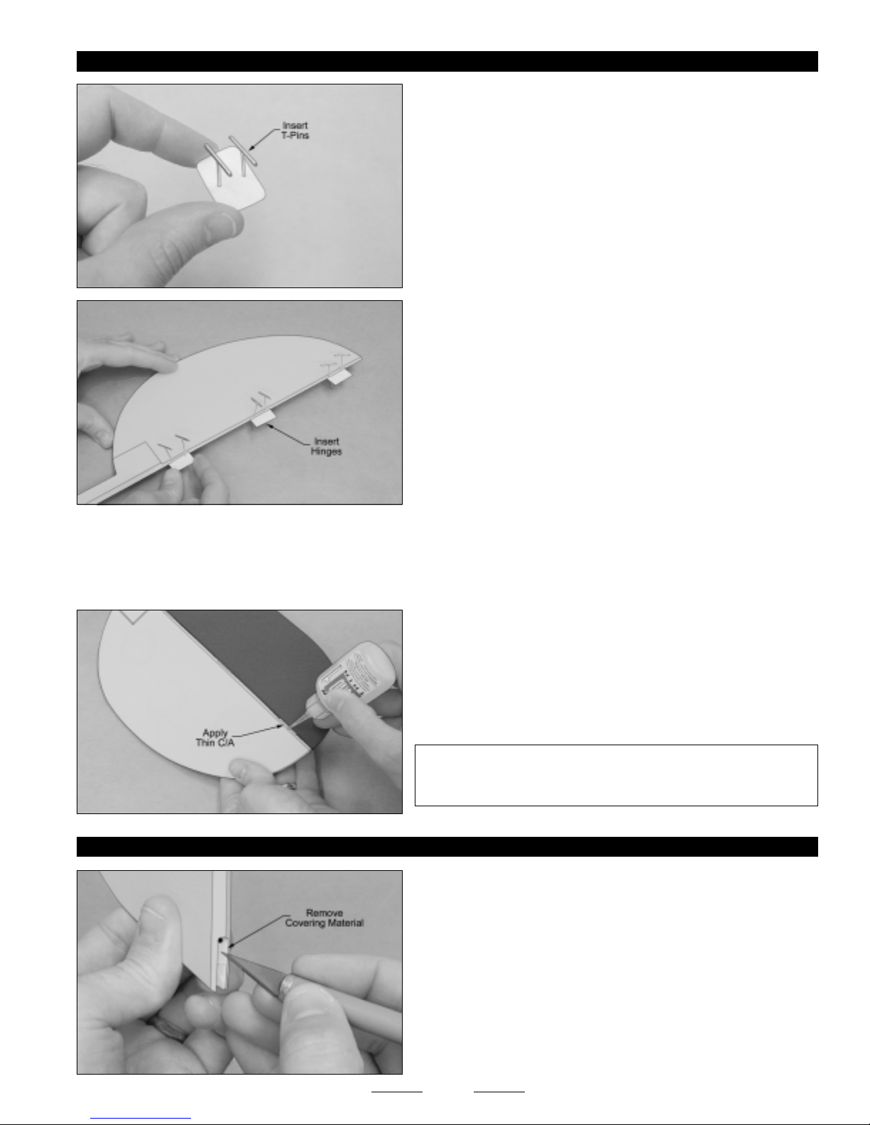
❑ Push two T-Pins through the center of six C/A-style elevator hinges,
as shown.
The T-Pins will keep the hinges centered and square to the
☞
hinge line while you are hinging the elevator.
❑ Slide one hinge into each hinge slot in the elevator, making sure that
you push each hinge in up to the T-Pins.
Don't glue the hinges into the elevator yet.
☞
❑ Push the elevator and its hinges into the hinge slots in the trailing edge of the horizontal stabilizer.
❑ Remove the T-Pins and push the elevator into its final position. The elevator should be pushed firmly up against the trailing
edge, so that there is a minimal hinge gap (no more than 1/32" wide), and the tips of the elevator should be even with the tips of
the stabilizer.
❑ While holding the elevator tight against the trailing edge of the
stabilizer, pivot the elevator down about 45º and apply 5-6 drops of thin
C/A to the exposed area of each hinge. Turn the fuselage over and
repeat for the other side of the hinges.
Remove any C/A that may run down the hinge line, using C/A
☞
Debonder.
STEP 3: INSTALLING THE TAIL WHEEL WIRE
✦✦
✦IMPORTANT
✦✦
check the integrity of the hinges. If one or more hinges is loose, apply
more C/A to those hinges to secure them into place.
❑ Using a modeling knife, carefully cut away and remove the covering
material from over the precut groove in the bottom of the leading edge
of the rudder.
✦✦
✦ After the C/A fully cures, pull on the elevator to
✦✦
Notice that there is a predrilled hole in the top of the precut groove to
☞
accept the tail wheel wire.
19
Continued On Next Page
☛☛
☛
☛☛
Page 20
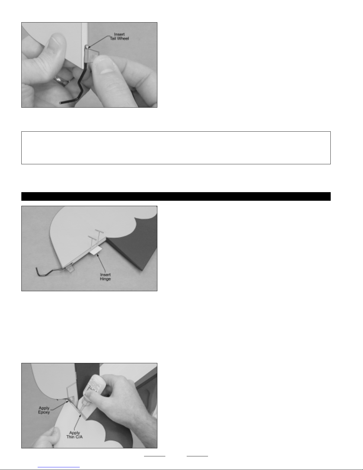
❑ Test-fit the tail wheel wire into the predrilled hole and groove. When
properly aligned, the front edge of the tail wheel wire should be flush
with the leading edge of the rudder and the nylon bearing should rest
within the precut groove.
❑ When satisfied with the fit and alignment, remove the tail wheel wire and use 220 grit sandpaper to roughen only the gluing
surface of the wire.
✦✦
✦WARNING
✦✦
and the nylon bearing. If you do, the rudder won't be able to pivot right and left. Do not glue the nylon bearing into the groove in
the rudder either. We suggest applying lightweight oil or petroleum jelly to the pivot point of the nylon bearing to prevent this. Do
not get any oil or petroleum jelly on the mounting tab.
❑ Glue the tail wheel wire into the rudder, using a generous amount of 5 minute epoxy. Remove any excess epoxy, using a paper
towel and rubbing alcohol, and allow the epoxy to set up before proceeding.
STEP 4: HINGING THE RUDDER
❑ Using a modeling knife, cut away and remove the covering material from over the precut nylon bearing groove in the back edge
of the fuselage.
✦✦
✦ When gluing the tail wheel wire into the rudder in the next procedure, do not get epoxy between the tail wheel wire
✦✦
❑ Push two T-Pins through the center of one C/A-style rudder hinge.
❑ Slide the hinge into the hinge slot in the rudder, making sure that you
push the hinge in up to the T-Pins.
Don't glue the hinge into the rudder yet.
☞
❑ Use 220 grit sandpaper with a sanding block to lightly sand each side of the mounting tab on the nylon bearing to roughen the
smooth surface, then apply a thin layer of lightweight oil or petroleum jelly to the pivot point of the nylon bearing to prevent epoxy
from gluing the nylon bearing to the tail wheel wire.
❑ Mix a small quantity of 5 minute epoxy and apply a thin layer to ONLY the mounting tab on the nylon bearing and into the precut
groove in the back edge of the fuselage.
❑ Hinge the rudder to the fuselage, using the same techniques that
you used to hinge the elevator to the stabilizer. The bottom of the
rudder should be even with the bottom of the fuselage and the rudder
counterbalance should not rub against the top of the fuselage. There
should also not be more than a 1/32" wide hinge gap.
❑ Allow the C/A and epoxy to dry for about 15 minutes, then pivot
the rudder right and left several times to free up the hinges. Like
with the aileron hinges, if there is any excess dried epoxy on the nylon
bearing, it can be carefully cut away using the tip of your modeling knife.
20
Page 21
SECTION 11: LANDING GEAR INSTALLATION
YOU'LL NEED THE FOLLOWING PARTS FROM THE KIT:
❑ (1) Steel Axle
❑ (1) Aluminum Tube
❑ (2) Main Gear Wheels
❑ (2) Nylon Spacers
❑ (2) Wheel Collars
❑ (2) M3 x 6mm Machine Screws
YOU'LL NEED THE FOLLOWING TOOLS AND SUPPLIES:
❑ Pacer Z-42 Blue Threadlocker
❑ # 2 Phillips Head Screwdriver
❑ Excel Modeling Knife
✦✦
✦IMPORTANT
✦✦
and hard-packed dirt. If you will be flying off of grass, we suggest replacing the stock wheels with larger wheels suitable for your
grass flying field. Larger diameter wheels will make it easier to land and take off on grass runways.
STEP 1: INSTALLING THE ALUMINUM SUPPORT TUBE
✦✦
✦ The wheels included with the Speedy Bee ARF are suitable for use on hard surfaces, such as concrete, asphalt
✦✦
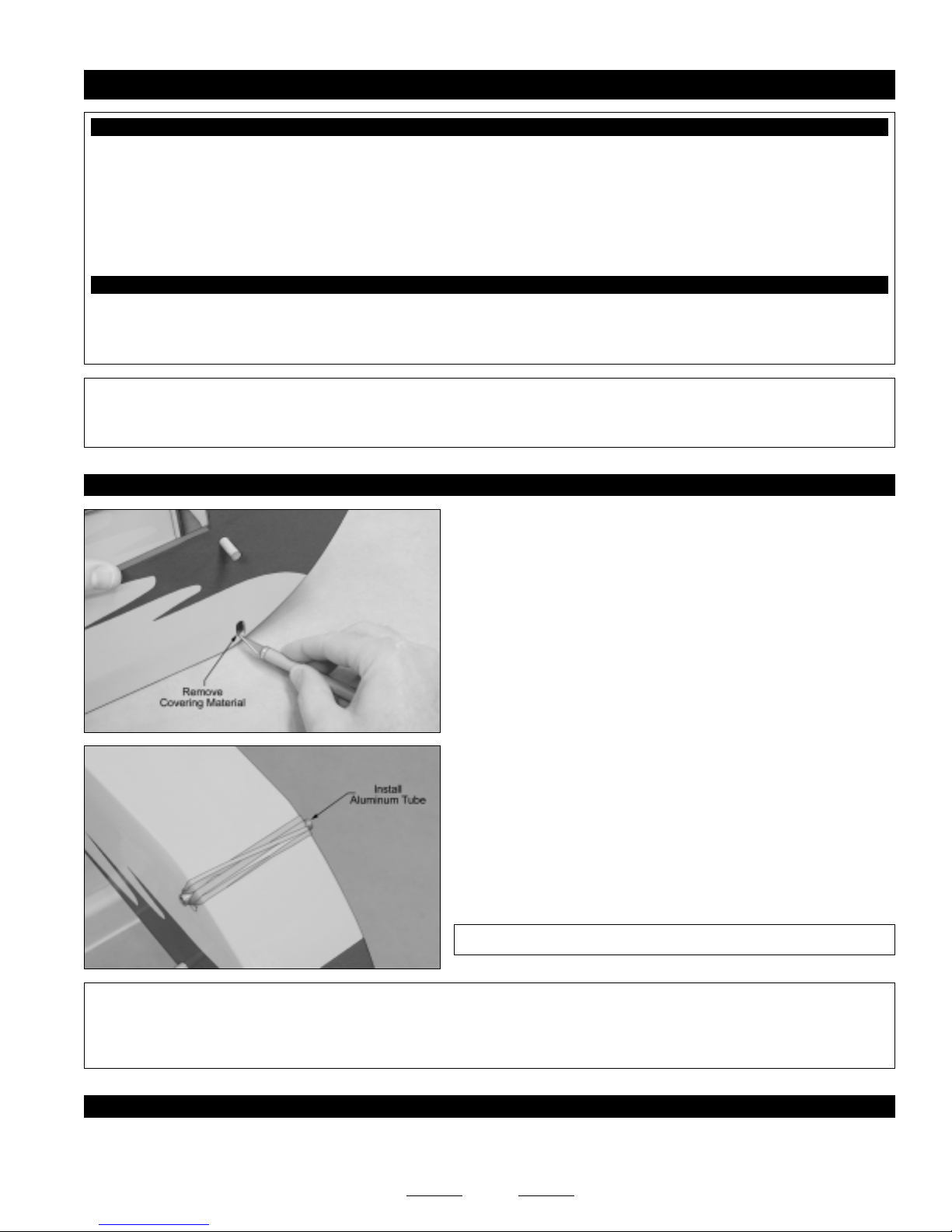
❑ Using a modeling knife, cut away and remove the covering material
from over the precut, oval-shaped hole in each side of the fuselage. If
you look carefully, you should be able to see each oval-shaped hole
underneath the covering material.
❑ (2) Rubber Bands
❑ (1) Tail Wheel
❑ (1) Nylon Spacer
❑ (1) Wheel Collar
❑ (1) M3 x 5mm Machine Screw
❑ Ernst Airplane Stand
❑ Ruler
✦✦
✦IMPORTANT
✦✦
bands that hold the axle assembly in place allow the axle assembly to move like a shock absorber. The rubber bands should be
tight enough to keep the axle support tube from sliding back and forth, but not so tight that the axle support tube can't be pushed
up. It may be necessary to loop one or both rubber bands around the axle support tube twice to achieve the desired results.
STEP 2: INSTALLING THE AXLE AND WHEELS
❑ Slide the steel axle through the aluminum tube, making sure that each end of the axle is equal distance from the ends of the
aluminum tube.
✦✦
✦ The holes in the fuselage side are oval-shaped so that the axle assembly can move up and down. The rubber
✦✦
❑ Slide the aluminum tube through the oval-shaped holes in the
fuselage and center it, making sure that each end of the aluminum tube
is equal distance from the fuselage sides.
❑ Secure the aluminum tube to the fuselage by looping the two rubber
bands over one end the aluminum tube, stretching them across the
bottom of the fuselage and looping them around the other end of the
aluminum tube.
✦✦
✦IMPORTANT
✦✦
21
✦✦
✦ Do NOT glue the aluminum tube into the fuselage.
✦✦
Continued On Next Page
☛☛
☛
☛☛
Page 22
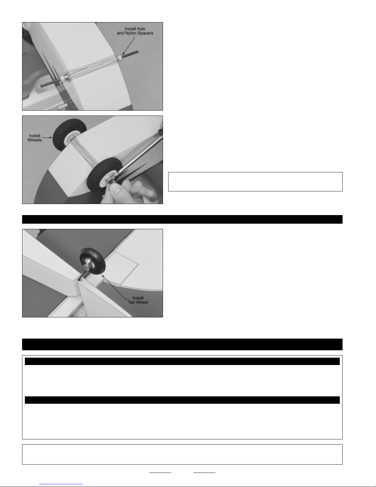
❑ While keeping the axle centered, carefully slide one nylon spacer
onto each end of the axle and push them up against the ends of the
aluminum tube.
❑ Slide one wheel onto each end of the axle. Secure the wheels into
place, using two wheel collars and two M3 x 6mm machine screws.
We suggest applying Blue Threadlocker to the machine screws to
☞
prevent them from loosening during flight.
STEP 3: INSTALLING THE TAIL WHEEL
SECTION 12: ENGINE INSTALLATION
✦✦
✦IMPORTANT
✦✦
both wheels spin freely.
❑ Slide the nylon spacer onto the tail wheel wire, followed by the tail
wheel. Use the wheel collar and one M3 x 5mm machine screw to hold
the tail wheel in place.
✦✦
✦ After installing the wheel collars, double-check that
✦✦
YOU'LL NEED THE FOLLOWING PARTS FROM THE KIT:
❑ (2) Engine Mounting Beams
❑ (4) M3 x 18mm Machine Screws
❑ (4) M3 x 25mm Socket-Cap Screws
YOU'LL NEED THE FOLLOWING TOOLS AND SUPPLIES:
❑ Kwik Bond Thick C/A
❑ # 2 Phillips Head Screwdriver
❑ 2.5mm Hex Wrench
❑ Adjustable Wrench
✦✦
✦IMPORTANT
✦✦
Section 23 on page # 38 at this time.
✦✦
✦ This section details the installation of a glow engine. If you will be installing an electric motor, please refer to
✦✦
❑ (4) M3 Lock Nuts
❑ (4) M3 Blind Nuts
❑ (12) M3 Flat Washers
❑ Electric Drill
❑ 5/64", 1/8" & 5/32" Drill Bits
❑ Ruler
❑ Pencil
22
Continued On Next Page
☛☛
☛
☛☛
Page 23
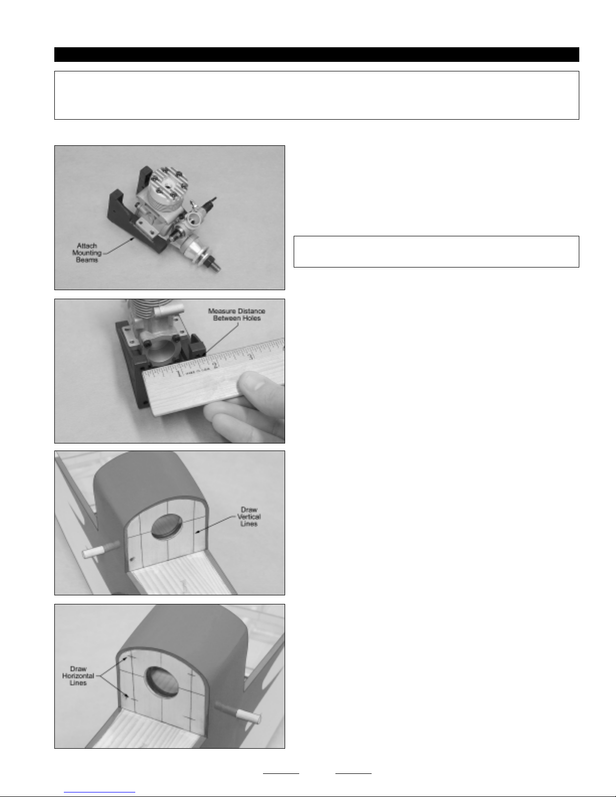
STEP 1: INSTALLING THE ENGINE MOUNTING BEAMS
✦✦
✦IMPORTANT
✦✦
engine, the installation procedures are the same. The Magnum XL .28A engine is shown.
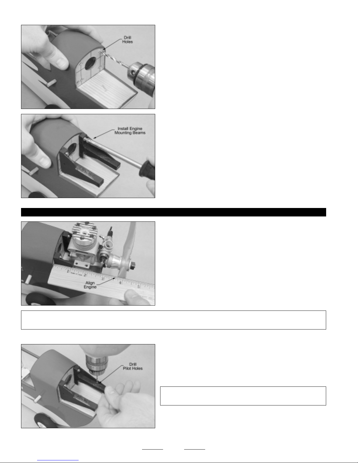
To aid in alignment, the horizontal and vertical thrust lines have been predrawn onto the firewall for you.
❑ Remove the muffler and high speed needle valve assembly from your engine and set them aside.
✦✦
✦ The following procedures outline the installation of a two-stroke engine. If you are installing a four-stroke
✦✦
❑ Temporarily glue the two engine mounting beams to your engine's
mounting lugs, using a couple of drops of thick C/A.
The location of the engine is not important at this time. It's more
☞
important that the beams are square to the mounting lugs.
✦✦
✦IMPORTANT
✦✦
beam should face up, as shown.
❑ Using a ruler, measure the width between the centerline of the
holes in the two engine mounting beams.
✦✦
✦ The precut notch in the right-side engine mounting
✦✦
This distance will vary depending on the width of your engine's
☞
crankcase.
❑ Divide the measurement found in the previous procedure in half.
❑ Measure this resulting distance and draw one vertical line to the right
of the vertical thrust line and one vertical line to the left of the vertical
thrust line.
Make sure that the two vertical lines you draw are parallel to the
☞
vertical thrust line.
❑ Using a ruler and a pencil, measure and draw a horizontal line 1/2"
above the horizontal thrust line, then measure and draw a horizontal
line 13/16" below the horizontal thrust line.
Again, make sure that the two horizontal lines you draw are parallel
☞
to the horizontal thrust line.
23
Continued On Next Page
☛☛
☛
☛☛
Page 24
STEP 2: INSTALLING THE ENGINE
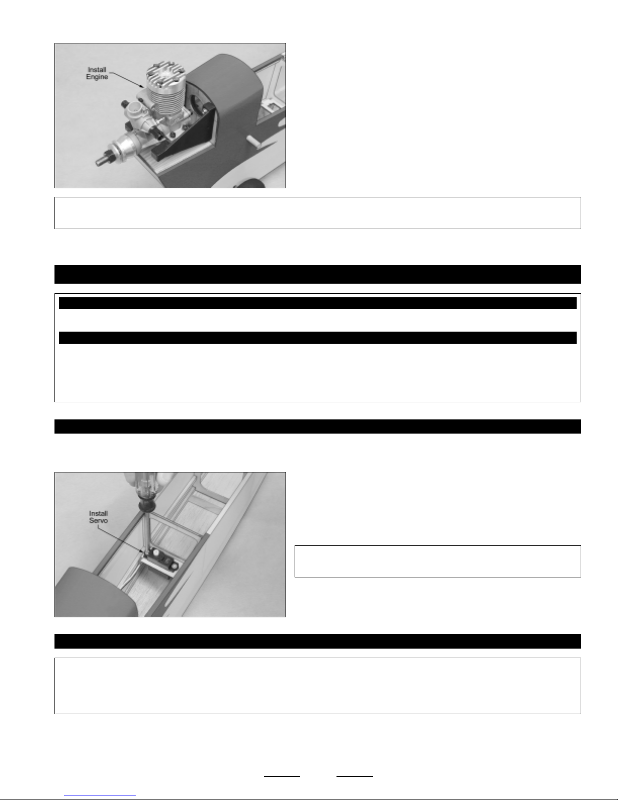
❑ Using a drill with a 5/32" diameter drill bit, drill a hole through the
firewall at each of the four intersecting lines.
❑ Remove your engine from the engine mounting beams and install
them onto the firewall, using four M3 x 18mm machine screws, four M3
flat washers and four M3 blind nuts. Tighten the screws firmly to draw
the blind nuts into the back of the firewall.
Note that the engine mounting beam with a notch in it is mounted
☞
on the right side of the firewall.
❑ Install a propeller onto your engine, then set your engine onto the
engine mounting beams.
❑ Using a ruler, measure the distance from the firewall to the back
edge of the propeller (nearest the hub). Adjust the depth of the engine
so that the measurement is 3-5/8".
✦✦
✦IMPORTANT
✦✦
the engine forward (to clear the rear-mounted carburetor of a four-stroke engine, for instance) it won't cause any problem.
❑ Using a pencil, carefully mark the locations of the engine mounting holes onto the engine mounting beams.
✦✦
✦ The 3-5/8" measurement is not set in stone. Frankly, for this airplane, it's not very critical. If you need to move
✦✦
❑ Remove the engine and drill 5/64" diameter pilot holes through the
engine mounting beams at the marks you drew.
✦✦
✦IMPORTANT
✦✦
and not at an angle.
✦✦
✦ Be careful that you drill the holes straight down
✦✦
❑ Carefully enlarge the 5/64" diameter pilot holes, using a 1/8" diameter drill bit.
24
Continued On Next Page
☛☛
☛
☛☛
Page 25
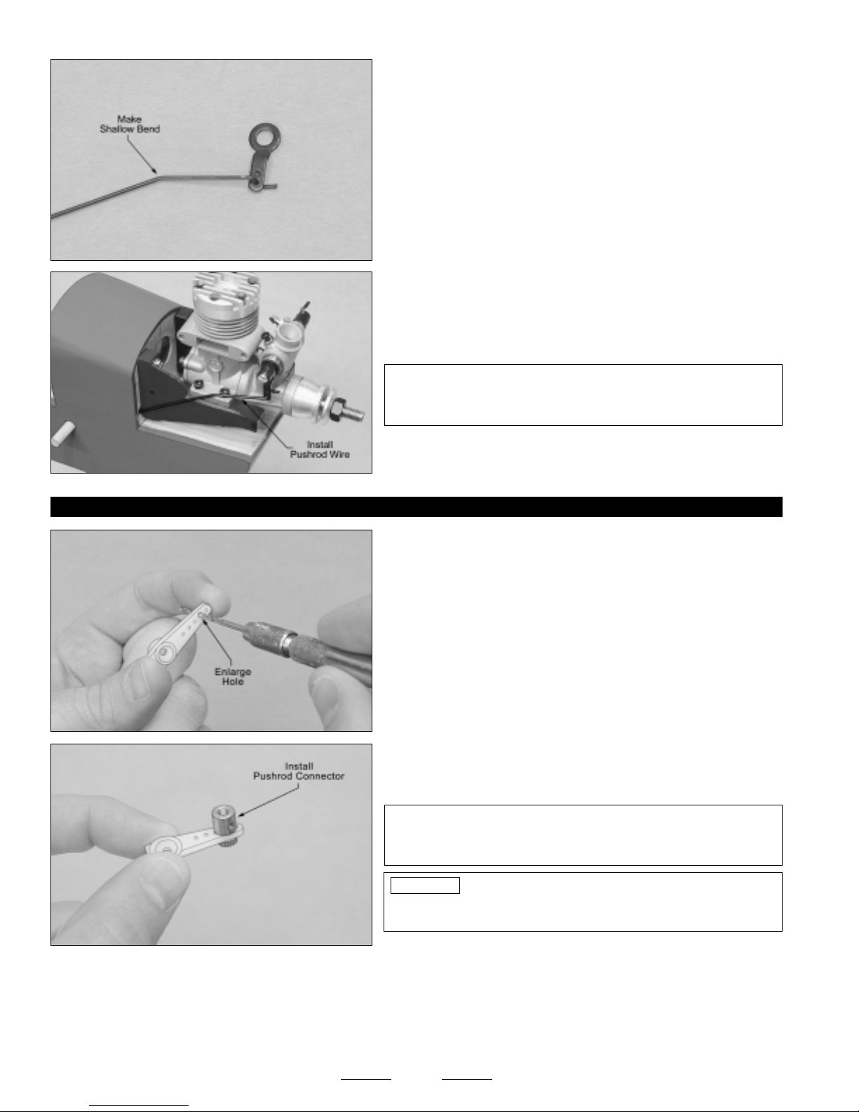
❑ Remove the engine mounting beams from the firewall, then install
the engine onto the engine mounting beams, using four M3 x 25mm
socket-cap screws, eight M3 flat washers and four M3 lock nuts.
Tighten the screws and lock nuts firmly to hold the engine securely
☞
into place.
❑ Reinstall the engine mounting beams onto the firewall.
✦✦
✦IMPORTANT
✦✦
you wouldn't be able to access them.
✦✦
✦ You must remove the engine mounting beams so that you can install and tighten the M3 hex nuts; otherwise,
✦✦
SECTION 13: THROTTLE CONTROL SYSTEM INSTALLATION
YOU'LL NEED THE FOLLOWING PARTS FROM THE KIT:
❑ (1) 11-3/4" Plain Wire w/Z-Bend
YOU'LL NEED THE FOLLOWING TOOLS AND SUPPLIES:
❑ Kwik Bond Thin C/A
❑ # 1 & # 2 Phillips Head Screwdrivers
❑ Wire Cutters
❑ Needle Nose Pliers
STEP 1: INSTALLING THE THROTTLE SERVO
❑ Install the rubber grommets and brass collets onto your throttle servo, making sure to install the collets with the flanges toward
the bottom of the servo.
❑ (1) Adjustable Pushrod Connector w/Machine Screw & Nut
❑ Electric Drill
❑ 1/16" & 5/64" Drill Bits
❑ Ruler
STEP 2: INSTALLING THE THROTTLE PUSHROD WIRE
✦✦
✦IMPORTANT
✦✦
positioned to line up with the throttle arm on most two-stroke engines within the specified size range. If you are using a four-stroke
engine, you may need to flip your engine's carburetor so that the throttle arm is on the right side of the engine. You may also need
to modify the position of the plastic guide tube so that the pushrod wire will line up with your engine's throttle arm.
❑ Remove the throttle arm from your engine and install the Z-Bend in the pushrod wire into the outermost hole in the throttle arm.
You may need to enlarge the hole in your engine's throttle arm to accommodate the diameter of the wire.
☞
✦✦
✦ The plastic pushrod guide tube for the throttle pushrod wire has been preinstalled from the factory. This tube is
✦✦
❑ Install the throttle servo into the plywood servo tray, making sure to
drill 1/16" diameter pilot holes for the mounting screws.
✦✦
✦IMPORTANT
✦✦
side of the fuselage, as shown.
25
✦✦
✦ The servo output shaft should be toward the right
✦✦
Continued On Next Page
☛☛
☛
☛☛
Page 26
❑ Using a pair of pliers, make a shallow bend in the pushrod wire, 1"
behind the Z-Bend. This will allow the pushrod wire to line up with the
throttle arm when it's installed.
❑ Slide the plain end of the throttle pushrod wire into the plastic guide
tube in the firewall, then reinstall the throttle arm onto your engine.
✦✦
✦IMPORTANT
✦✦
need to adjust the bend in the pushrod wire so that it lines up better
with your engine's throttle arm.
STEP 3: INSTALLING THE ADJUSTABLE PUSHROD CONNECTOR
❑ Using a modeling knife, cut away all but one arm from a "4-point"
servo horn.
❑ Enlarge the hole in the servo arm that is 11/16" out from the center of
the servo arm, using a 5/64" diameter drill bit.
❑ Install the adjustable pushrod connector into the enlarged hole in
the servo arm.
✦✦
✦ So that the pushrod wire doesn't bind, you may
✦✦
❑ Connect your radio system and plug the throttle servo into the receiver. Check to ensure that the throttle servo output shaft
is rotating in the correct direction. When the throttle control stick is moved forward, from the idle to the full throttle position, the
servo output shaft should rotate in the correct direction to open your engine's carburetor. If it doesn't, flip the servo reversing
switch on your transmitter.
For the Magnum XL .28A, the servo output shaft should rotate counterclockwise to open the carburetor.
☞
✦✦
✦IMPORTANT
✦✦
the nut completely. You don't want the pushrod connector loose, but
you do want it to be able to rotate without binding.
PRO TIP
apply a drop of thin C/A to it. Allow the C/A to fully cure before
proceeding.
26
✦✦
✦ When threading on the knurled nut, don't tighten
✦✦
To prevent the knurled nut from loosening during flight,
Continued On Next Page
☛☛
☛
☛☛
Page 27
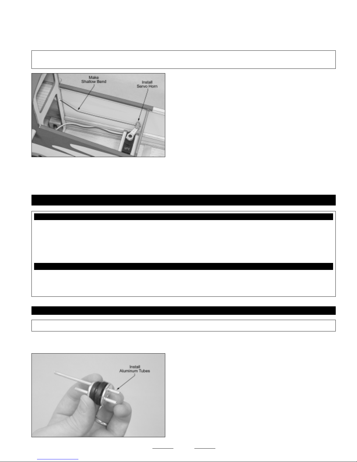
❑ Position the throttle control stick and the throttle trim lever on your transmitter to their lowest positions.
❑ Slide the adjustable pushrod connector/servo horn assembly over the plain end of the throttle pushrod wire.
✦✦
✦IMPORTANT
✦✦
pushrod wire will line up with the adjustable pushrod connector without binding.
❑ Operate the throttle several times to ensure that the pushrod wire does not bind and that the carburetor opens and closes
completely. You may need to adjust your transmitter EPA settings to achieve perfect settings.
✦✦
✦ You will need to make a shallow bend in the pushrod wire where it exits the plastic guide tube, so that the
✦✦
❑ After making sure that the carburetor is in the fully closed position,
angle the servo horn back as far as possible without hitting the plywood
fuselage bulkhead.
❑ While holding the carburetor fully closed, install and tighten the
machine screw in the top of the adjustable pushrod connector.
❑ Use wire cutters to cut away and remove the excess pushrod wire,
then install and tighten the servo horn retaining screw to hold the servo
horn securely to the servo.
SECTION 14: FUEL TANK ASSEMBLY AND INSTALLATION
YOU'LL NEED THE FOLLOWING PARTS FROM THE KIT:
❑ (1) 85cc Fuel Tank
❑ (1) Large Diameter Metal Plate
❑ (1) Small Diameter Metal Plate
❑ (1) Neck-Reinforcement Ring
❑ (1) Rubber Stopper
❑ (1) Fuel Pick-Up "Clunk"
❑ (1) M3 x 20mm Machine Screw
❑ (1) Silicone Fuel Tubing
❑ (3) Aluminum Tubing
YOU'LL NEED THE FOLLOWING TOOLS AND SUPPLIES:
❑ # 2 Phillips Head Screwdriver
❑ Excel Modeling Knife
❑ Scissors
STEP 1: ASSEMBLING THE RUBBER STOPPER
✦✦
✦IMPORTANT
✦✦
❑ Using 220 grit sandpaper, carefully smooth and deburr each end of the two aluminum tubes. This will prevent the fuel tubing
from being accidentally cut when it is installed later.
✦✦
✦ Discard the shortest of the aluminum tubes. It will not be used for our style of fuel tank setup.
✦✦
❑ Push the two aluminum tubes through the rubber stopper. Slide the
large diameter metal plate over the tubes at the front of the rubber
stopper and slide the small diameter metal plate over the tubes at the
rear of the rubber stopper.
❑ Using a ruler, measure the distance that the two aluminum tubes
protrude from the front of the stopper assembly. This distance should
be 3/8". If it is not, adjust the tubes by pushing them forward or
backward until you are satisfied with the alignment.
❑ Ruler
❑ 220 Grit Sandpaper w/Sanding Block
27
Continued On Next Page
☛☛
☛
☛☛
Page 28
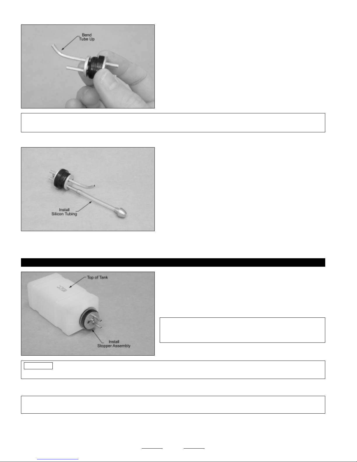
❑ Carefully bend the longer of the two aluminum tubes up at a shallow
angle, being careful not to kink the tubing as you bend it. Make the
shallow bend near the back of the stopper and cut off the excess tubing,
so that the vent opening will be nearer the middle of the fuel tank and
not in the back of the fuel tank.
✦✦
✦IMPORTANT
✦✦
rest just below the top of the fuel tank.
❑ Secure one end of the silicone fuel tubing onto the end of the fuel pick-up "clunk."
❑ Push the M3 x 20mm machine screw through the front of the stopper assembly and partially thread it into the small diameter
metal backplate. Don't tighten the machine screw yet or you won't be able to install the stopper assembly into the fuel tank.
STEP 2: INSTALLING THE STOPPER ASSEMBLY
✦✦
✦ When the stopper assembly is installed in the fuel tank, the top of the vent tube (the tube you just bent) should
✦✦
❑ Slide the silicone fuel tubing, with the fuel pick-up attached, onto the
end of the aluminum fuel pick-up tube (straight tube). While holding the
aluminum tube in place, adjust the length of the silicone tubing until the
end of the fuel pick-up is 2-3/4" back from the rear of the stopper
assembly.
PRO TIP
inside of the fuel tank, making it easy to see the tubing inside.
❑ When satisfied with the alignment, tighten the machine screw until the rubber stopper expands and seals the fuel tank opening.
✦✦
✦IMPORTANT
✦✦
the fuel tank.
❑ With the rubber stopper assembly installed, double-check to make sure that the fuel pick-up can move freely inside the fuel tank.
Ideally, the fuel pick-up should be about 1/4" in front of the back of the fuel tank. This will ensure that the fuel pick-up can't get stuck
in the back of the fuel tank during flight.
If you have trouble seeing the vent tube, hold the fuel tank assembly up to a bright light. This will illuminate the
✦✦
✦ Don't overtighten the machine screw or you might strip the threads in the small metal plate or split the front of
✦✦
❑ Push the metal neck-reinforcement ring over the neck of the molded
fuel tank opening, then carefully push the stopper assembly into the
molded hole in the front of the fuel tank and rotate the stopper assembly
until the aluminum vent tube rests just below the top of the fuel tank.
✦✦
✦IMPORTANT
✦✦
lettering on it. Make sure that the vent tube is orientated toward the
top of the fuel tank.
28
✦✦
✦ The top of the fuel tank has the molded "85cc"
✦✦
Continued On Next Page
☛☛
☛
☛☛
Page 29
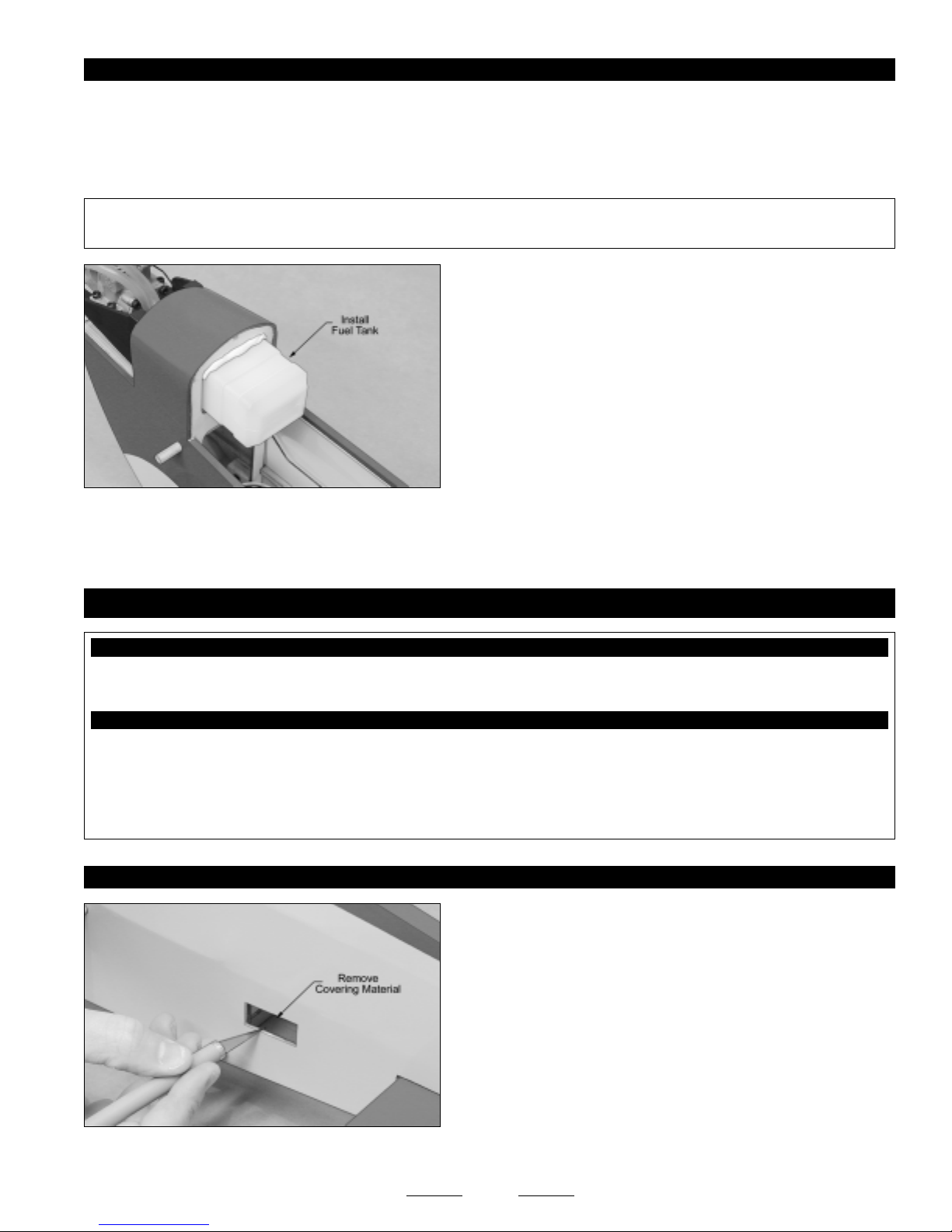
STEP 3: INSTALLING THE FUEL TANK
❑ Cut two pieces of silicone fuel tubing (not included) to a length of 4" and install them onto the aluminum tubes at the front of
the fuel tank.
❑ Feed the ends of the fuel tubing through the predrilled hole in the firewall and slide the fuel tank into position, making sure that
the stopper assembly lines up with, and is firmly pushed into, the predrilled hole in the firewall.
✦✦
✦IMPORTANT
✦✦
Remember, the top of the fuel tank has the molded "85cc" lettering in it.
Keep in mind that there are fuel tank supports in the wing, so when the wing is installed, they will support the back of the fuel
☞
tank and also keep it from sliding backward. It's still important to secure it firmly in place, though.
✦✦
✦ When you slide the fuel tank into position, make sure that the top of the fuel tank is toward the top of the fuselage.
✦✦
❑ Use your favorite method to secure the fuel tank into position. We
wedged a thin piece of foam rubber between the top of the fuel tank and
the forward bulkhead. Alternatively, you could hold the fuel tank in place
using a bead of silicon sealant.
SECTION 15: ELEVATOR CONTROL SYSTEM INSTALLATION
YOU'LL NEED THE FOLLOWING PARTS FROM THE KIT:
❑ (1) 5-1/2" Threaded Wire w/Z-Bend
❑ (1) Nylon Control Horn w/Backplate
❑ (1) Nylon Clevis
❑ (2) M2 x 12mm Machine Screws
YOU'LL NEED THE FOLLOWING TOOLS AND SUPPLIES:
❑ Kwik Bond Thin C/A
❑ # 1 Phillips Head Screwdriver
❑ Needle Nose Pliers
❑ Excel Modeling Knife
❑ Electric Drill
STEP 1: INSTALLING THE ELEVATOR SERVO
❑ Install the rubber grommets and brass collets onto your elevator servo, making sure to install the collets with the flanges toward
the bottom of the servo.
❑ 1/16" & 5/64" Drill Bits
❑ Ernst Airplane Stand
❑ Ruler
❑ Pencil
❑ Masking Tape
❑ Using a modeling knife, cut away and remove the covering material
from over the elevator servo mounting hole in the left side of the
fuselage. The hole is located 6-1/4" in front of the rudder hinge line and
1-1/2" up from the bottom of the fuselage.
Like the aileron servo mounting holes, the elevator servo mounting
☞
servo hole is sized to fit most standard-size mini servos. You may need
to enlarge the hole slightly to fit your particular servo.
29
Continued On Next Page
☛☛
☛
☛☛
Page 30
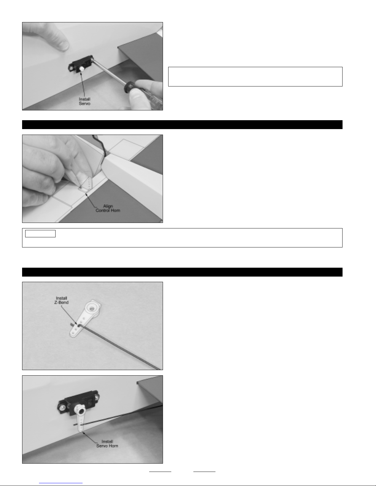
❑ Install the elevator servo, making sure to drill 1/16" diameter pilot
holes for the mounting screws.
✦✦
✦IMPORTANT
✦✦
of the fuselage, as shown.
STEP 2: INSTALLING THE CONTROL HORN
❑ Position the nylon control horn onto one left side of the elevator.
When aligned properly, the centerline of the control horn should be
1-3/16" out from the fuselage side (at the hinge line) and the clevis
attachment holes should be lined up over the hinge line. The base of
the control horn should be parallel to the hinge line, too, so that the
control horn will line up with the pushrod wire.
❑ When satisfied with the alignment, mark and drill 5/64" diameter
pilot holes through the elevator for the control horn mounting screws.
PRO TIP
the C/A to fully cure. The C/A will harden the surrounding balsa, making the mounting area stronger.
Before installing the control horn in the next procedure, drip several drops of thin C/A into the pilot holes and allow
✦✦
✦ The servo output shaft should be toward the front
✦✦
❑ Install the control horn and backplate, using two M2 x 12mm machine screws, being careful not to overtighten them.
STEP 3: INSTALLING THE PUSHROD ASSEMBLY
❑ Using a modeling knife, cut away all but one arm from a "4-point"
servo horn.
❑ Install the Z-Bend in the pushrod wire into the hole in the servo arm
that is 9/16" out from the center of the servo arm.
❑ Connect your radio system and plug the elevator servo into the
receiver. Center the servo by double-checking that the elevator trim
lever on your transmitter is centered, then use a couple of pieces of
masking tape, taped between the elevator and the stabilizer, to hold the
elevator centered.
❑ Install the servo horn onto the servo, making sure that the servo
horn is centered and pointing down toward the bottom of the fuselage.
❑ Install the servo horn retaining screw to secure the servo horn to
the servo.
30
Continued On Next Page
☛☛
☛
☛☛
Page 31
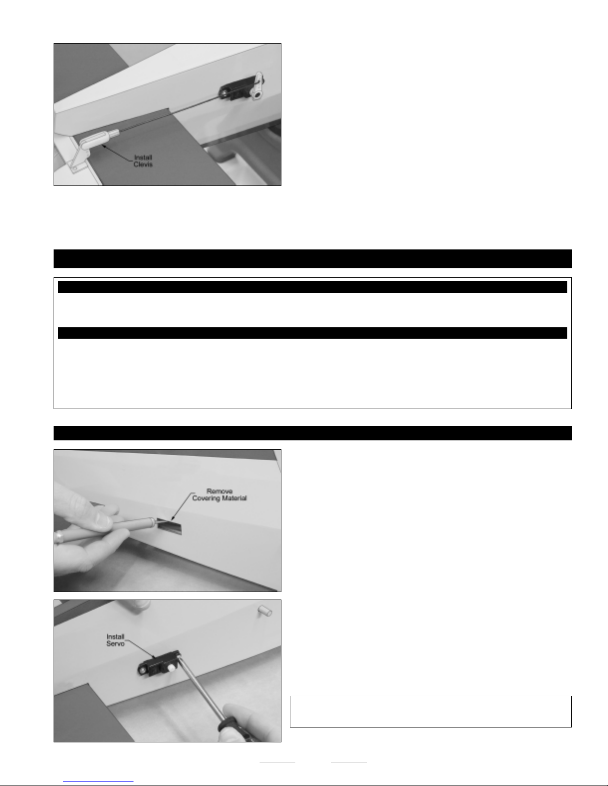
❑ Thread the nylon clevis onto the pushrod wire and snap the clevis
into the outermost hole in the control horn.
Hold the pushrod wire with a pair of pliers to prevent it from turning
☞
or twisting when installing the clevis.
❑ Remove the masking tape from the elevator and double-check that
both the servo horn and the elevator are still centered. If the elevator
is not centered, adjust the clevis until it is.
❑ Move the elevator up and down several times to ensure that the pushrod assembly does not bind. It should operate smoothly in
both directions.
SECTION 16: RUDDER CONTROL SYSTEM INSTALLATION
YOU'LL NEED THE FOLLOWING PARTS FROM THE KIT:
❑ (1) 6-1/8" Threaded Wire w/Z-Bend
❑ (1) Nylon Control Horn w/Backplate
YOU'LL NEED THE FOLLOWING TOOLS AND SUPPLIES:
❑ Kwik Bond Thin C/A
❑ # 1 Phillips Head Screwdriver
❑ Needle Nose Pliers
❑ Excel Modeling Knife
❑ Electric Drill
❑ (1) Nylon Clevis
❑ (2) M2 x 12mm Machine Screws
❑ 1/16" & 5/64" Drill Bits
❑ Ernst Airplane Stand
❑ Ruler
❑ Pencil
❑ Masking Tape
STEP 1: INSTALLING THE RUDDER SERVO
❑ Cut away and remove the covering material from over the rudder
servo mounting hole in the right side of the fuselage. The servo
mounting hole is located 6-1/4" in front of the rudder hinge line and
1-1-2" up from the bottom of the fuselage.
Again, you may need to enlarge the hole to fit your rudder servo.
☞
❑ Install the rubber grommets and brass collets onto your rudder servo,
making sure to install the collets with the flanges toward the bottom of
the servo.
❑ Install the rudder servo, making sure to drill 1/16" diameter pilot holes
for the mounting screws.
✦✦
✦IMPORTANT
✦✦
of the fuselage, as shown.
✦✦
✦ The servo output shaft should be toward the front
✦✦
31
Continued On Next Page
☛☛
☛
☛☛
Page 32
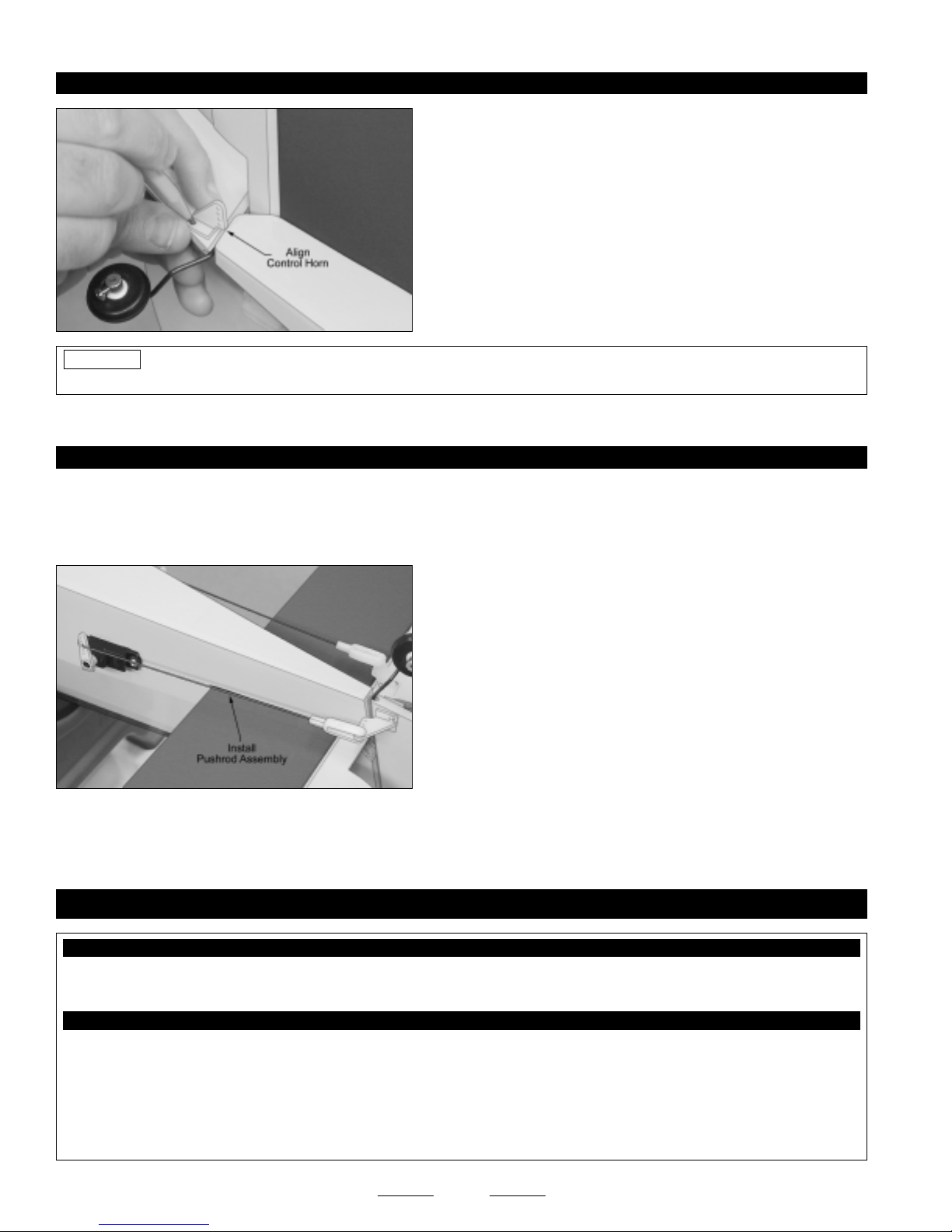
STEP 2: INSTALLING THE CONTROL HORN
❑ Position the nylon control horn onto one right side of the rudder.
When aligned properly, the centerline of the control horn should be 3/8"
up from the bottom of the rudder (at the hinge line) and the clevis
attachment holes should be lined up over the hinge line. The base of
the control horn should be angled up slightly, too, so that the control
horn will line up better with the pushrod wire.
❑ When satisfied with the alignment, mark and drill 5/64" diameter
pilot holes through the rudder for the control horn mounting screws.
PRO TIP
the C/A to fully cure. The C/A will harden the surrounding balsa, making the mounting area stronger.
❑ Install the control horn and backplate, using two M2 x 12mm machine screws, being careful not to overtighten them.
STEP 3: INSTALLING THE PUSHROD ASSEMBLY
❑ Connect your radio system and plug the rudder servo into the receiver. Center the servo by double-checking that the rudder
trim lever on your transmitter is centered.
❑ Use a couple of pieces of masking tape, taped between the rudder and the fuselage, to hold the rudder centered.
❑ Move the rudder right and left several times to ensure that the pushrod assembly does not bind. It should operate smoothly in
both directions.
Before installing the control horn in the next procedure, drip several drops of thin C/A into the pilot holes and allow
❑ Install the servo horn, pushrod wire and nylon clevis, using the same
techniques as you used to install the elevator servo horn, pushrod wire
and nylon clevis.
Like with the elevator pushrod assembly, the Z-Bend in the rudder
☞
pushrod wire should be 9/16" out from the center of the servo arm, and
the nylon clevis should be installed in the outermost hole in the control
horn. The servo horn should point down toward the bottom of the
fuselage, too.
SECTION 17: AILERON CONTROL SYSTEM INSTALLATION
YOU'LL NEED THE FOLLOWING PARTS FROM THE KIT:
❑ (2) 3-3/8" Threaded Wires w/Z-Bends
❑ (2) Nylon Control Horns
YOU'LL NEED THE FOLLOWING TOOLS AND SUPPLIES:
❑ Kwik Bond 5 Minute Epoxy
❑ # 1 Phillips Head Screwdriver
❑ Needle Nose Pliers
❑ Excel Modeling Knife
❑ Electric Drill
❑ 1/16" Drill Bit
❑ (2) Nylon Clevises
❑ (4) M2 x 10mm Wood Screws
❑ Ruler
❑ Pencil
❑ Masking Tape
❑ NHP Epoxy Mixing Sticks
❑ NHP Epoxy Mixing Cups
32
Continued On Next Page
☛☛
☛
☛☛
Page 33
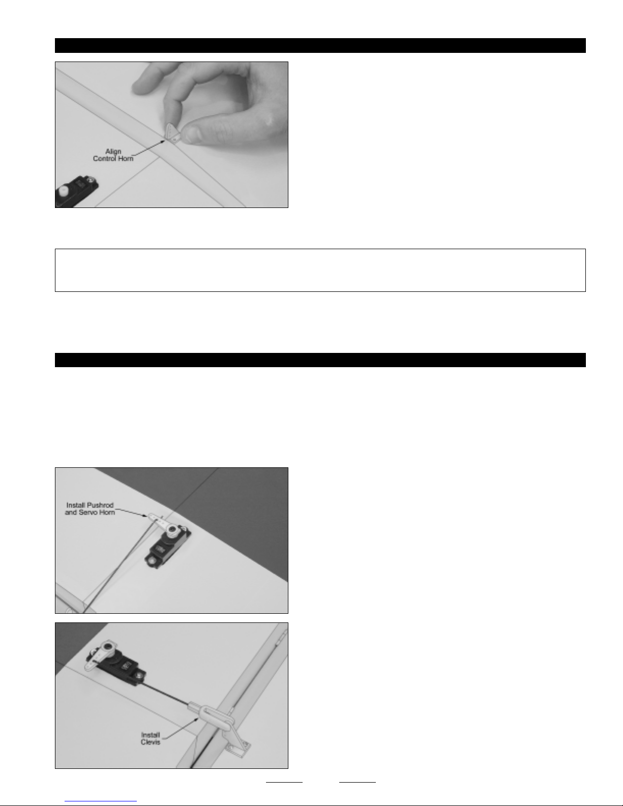
STEP 1: INSTALLING THE CONTROL HORNS
❑ Position one nylon control horn onto one aileron. When aligned
properly, the centerline of the control horn should be 7" out from the
inside edge of the aileron (at the hinge line) and the base of the control
horn should be parallel too, and lined up with, the front edge of the
aileron, so that the control horn will line up with the pushrod wire.
❑ When satisfied with the alignment, mark and drill 1/16" diameter pilot holes into the aileron for the control horn mounting
screws. Be careful not to drill through the top of the aileron!
✦✦
✦IMPORTANT
✦✦
backplate, we strongly suggest that you apply a drop or two of 5 minute epoxy to the wood screws before threading them into
place. The epoxy will ensure that the wood screws won't come loose during flight.
❑ Install the control horn to the aileron, using two M2 x 10mm wood screws.
❑ Repeat the previous procedures to align and install the second control horn onto the bottom of the other aileron.
STEP 2: INSTALLING THE PUSHROD ASSEMBLIES
❑ Using a modeling knife, cut away all but one arm from a "4-point" servo horn.
❑ Install the Z-Bend in one pushrod wire into the hole in the servo arm that is 9/16" out from the center of the servo arm.
❑ Connect your radio system and plug one aileron servo into the receiver. Center the servo by double-checking that the aileron
trim lever on your transmitter is centered, then use a couple of pieces of masking tape, taped between the aileron and the wing, to
hold the aileron centered.
✦✦
✦ Because the control horn mounting screws thread directly into a plywood plate, instead of using a nylon
✦✦
❑ Install the servo horn onto the servo, making sure that the servo
horn is centered and points toward the wing tip.
❑ Install the servo horn retaining screw to secure the servo horn to
the servo.
❑ Thread one nylon clevis onto the pushrod wire and snap the clevis
into the outermost hole in the control horn.
Hold the pushrod wire with a pair of pliers to prevent it from turning
☞
or twisting when installing the clevis.
33
Continued On Next Page
☛☛
☛
☛☛
Page 34
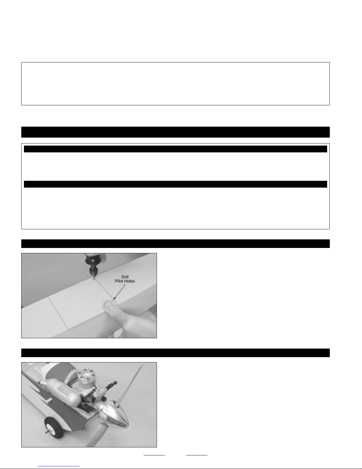
❑ Remove the masking tape from the aileron and double-check that the servo horn and the aileron are still centered. If the aileron
is not centered, adjust the clevis until it is. Move the aileron up and down several times to ensure that the linkage assembly does
not bind. It should operate smoothly in both directions.
❑ Repeat the previous procedures to install the second aileron pushrod assembly onto the other half of the wing.
✦✦
✦IMPORTANT
✦✦
will need to plug a Y-Harness into the two aileron servo leads at this time. This will allow both aileron servos to be plugged into the
aileron channel in your receiver.
If you will be flying your Speedy Bee ARF using a computer radio with mixing capabilities, you may want to plug each aileron servo
lead into your receiver separately (one into Ch. 1 and one into Ch. 6) to take advantage of your radio's mixing capabilities.
✦✦
✦ If you will be flying your Speedy Bee ARF using a non-computer radio system without mixing capabilities, you
✦✦
SECTION 18: FINAL ASSEMBLY
YOU'LL NEED THE FOLLOWING PARTS FROM THE KIT:
❑ (2) Plywood Mounting Plates (Optional)
❑ (1) Plastic Windscreen
❑ (5) M2 x 5mm Wood Screws
YOU'LL NEED THE FOLLOWING TOOLS AND SUPPLIES:
❑ Kwik Bond Thick C/A
❑ # 1 Phillips Head Screwdriver
❑ Excel Modeling Knife
❑ Scissors
❑ Electric Drill
❑ (2) M2 x 10mm Flange-Head Wood Screws
❑ (1) Decal Set
❑ 1/16" & 5/64" Drill Bits
❑ Ernst Airplane Stand
❑ Ruler
❑ Pencil
STEP 1: INSTALLING THE HATCH COVER
STEP 2: INSTALLING YOUR ENGINE ACCESSORIES
❑ With the hatch cover set in place and aligned, drill two 1/16"
diameter pilot holes through the back of the hatch cover for the mounting
screws. Position each hole 1/2" in from the fuselage sides and 3/16" in
front of the back edge of the hatch cover.
❑ Secure the hatch cover to the fuselage, using two M2 x 10mm
flange-head wood screws.
This hatch cover is used to access the flight battery if you have
☞
chosen to use an electric motor.
❑ Install your muffler, high speed needle valve, propeller and spinner.
Make sure to properly balance your propeller.
☞
❑ Connect the fuel lines from the fuel tank to your engine's carburetor
and muffler.
Installing a spinner is optional. A spinner adds to the looks of the
☞
airplane and makes starting your engine easier if you're using an
electric starter.
34
Continued On Next Page
☛☛
☛
☛☛
Page 35
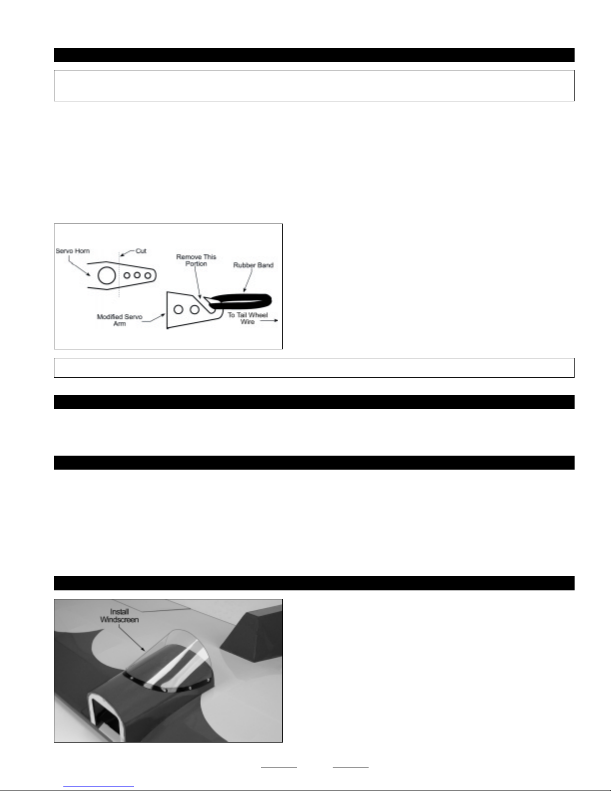
STEP 3: INSTALLING THE RECEIVER AND BATTERY PACK
✦✦
✦IMPORTANT
✦✦
How the airplane initially balances will determine where you need to mount the receiver and battery pack.
❑ Wrap the receiver and battery pack in foam rubber to protect them from vibration. Use masking tape or rubber bands to hold the
foam in place. Do not wrap the foam rubber too tightly or the vibration dampening quality will be reduced.
❑ After you've found the final location of the receiver and battery pack, mount them into the fuselage using your favorite method.
Strips of Velcro work well, or sandwich them in place using the two plywood plates glued between the fuselage sides. If you use the
plywood plates, you'll need to cut them to the proper length to fit the width of the fuselage.
❑ After installing the receiver, drill a 5/64" diameter hole through the fuselage floor for the antenna to exit. Unwrap the receiver
antenna and feed it out through the hole.
✦✦
✦IMPORTANT
✦✦
✦✦
✦ We don't suggest permanently installing the receiver and battery pack until you have balanced the airplane.
✦✦
❑ Using a modeling knife, carefully make an antenna mount out of an
extra servo horn. Remove one of the arms and cut it into the shape
shown.
❑ Use the modified servo arm and a rubber band to secure the end of
the antenna to the tail wheel wire.
✦✦
✦ Do not cut the receiver antenna shorter or you will loose control of the airplane.
✦✦
STEP 4: INSTALLING THE ON/OFF SWITCH
❑ Mount the on/off switch to the fuselage side (opposite the muffler) and connect the battery lead to the switch, and the switch and
servo leads to the receiver.
STEP 5: APPLYING THE DECALS
❑ Using a clean cloth, wipe the airframe down completely to remove any dust, debris and oil. We suggest using rubbing alcohol to
wipe the airframe down in the areas where the decals will be applied.
❑ Cut out each of the decals and apply them, using the box cover photos for reference.
If any air bubbles form under the decals when you apply them, use a T-Pin to puncture the bubble and release the trapped air,
☞
then press the decal down.
STEP 6: INSTALLING THE WINDSCREEN
Before mounting the windscreen, for an added touch, apply 3/16"
☞
or 1/4" wide black striping tape (not included) around the base of the
windscreen to simulate the windscreen frame.
❑ Install the plastic windscreen onto the front wing deck, using five
M2 x 5mm wood screws. Drill 1/16" pilot holes through the windscreen
to make it easier to install the wood screws.
35
Page 36
SECTION 19: BALANCING THE SPEEDY BEE ARF
YOU'LL NEED THE FOLLOWING TOOLS AND SUPPLIES:
❑ Ruler ❑ Masking Tape
✦✦
✦
✦✦
IMPORTANT
and crash!
✦✦
✦
✦✦
It is critical that your airplane be balanced correctly. Improper balance will cause your airplane to lose control
Center of Gravity Location:
4-1/2" - 5" (114mm-127mm) back from the leading edge of the wing, measured at the fuselage sides.
✦✦
✦
✦✦
WARNING
FOR TEST-FLYING WE SUGGEST YOU START WITH THE C/G AT 4-3/4" (121MM), then move it farther back as you
become familiar with the flying characteristics of the airplane. It is not recommended that the C/G be located any farther
back than 5" (127mm).
✦✦
✦IMPORTANT
✦✦
❑ Install the wing onto the fuselage.
❑ Apply two short pieces of masking tape onto the bottom of the wing, 4-3/4" (121mm) back from the leading edge, measured
at the fuselage sides.
❑ Place your fingers on the masking tape, and carefully lift the airplane. If the nose of the airplane falls, the airplane is nose heavy.
To correct this, move the battery pack and/or receiver back far enough to bring the airplane into balance. If the tail of the airplane
falls, the airplane is tail heavy. To correct this, move the battery pack and/or receiver forward far enough to bring the airplane into
balance. When balanced correctly, the airplane should sit level or slightly nose down when you lift it up with your fingers at the
C/G location.
✦✦
✦
✦✦
This is the recommended C/G range.
✦✦
✦ Balance the Speedy Bee ARF with the fuel tank empty and the airplane fully assembled.
✦✦
Once you have flown and become familiar with the flight characteristics of the airplane, the C/G can be moved fore or aft within
☞
the C/G range to change the flight performance. Moving the C/G back will cause the airplane to be more responsive, but less stable.
Moving the C/G forward will cause the airplane to be more stable, but less responsive.
DO NOT FLY THE AIRPLANE BEYOND THE RECOMMENDED BALANCE RANGE OR AN
UNCONTROLLABLE CRASH COULD RESULT!
SECTION 20: CONTROL THROWS
The control throws listed in this section are for test-flying and general sport-flying. If you want the airplane to be more aerobatic and
responsive, we suggest increasing the control throws in small amounts until you find your desired settings.
TEST-FLYING and GENERAL SPORT-FLYING
Ailerons: 1/2" (12mm) Up & 1/2" (12mm) Down
Elevator: 5/16" (8mm) Up & 5/16" (8mm) Down
Rudder: 3/8" (10mm) Right & 3/8" (10mm) Left
✦✦
✦IMPORTANT
✦✦
✦✦
✦VERY IMPORTANT
✦✦
of the clear vinyl tubing provided and sliding one piece over each clevis. The tubing will prevent any chance of the clevises
opening during flight.
✦✦
✦ The control throws are measured from the widest point of the control surfaces.
✦✦
✦✦
✦ After you are finished adjusting the pushrods and control throws, we strongly suggest cutting 1/4" lengths
✦✦
36
Page 37

SECTION 21: PREFLIGHT CHECK AND SAFETY
●
Completely charge the transmitter and receiver batteries before your first day of flying.
●
Check every bolt and every glue joint in the airplane to ensure that everything is tight and well-bonded. This should
include all of the control surface hinges as well.
●
Double-check that you've installed and tightened all of the servo horn retaining screws.
●
Double-check that the receiver and battery pack are properly secured into the fuselage. There's nothing worse than the
battery pack coming loose during flight.
●
Double-check that the fuel tank is properly secured into the fuselage.
●
Double-check the balance of the airplane. Do this with the fuel tank EMPTY.
●
Check the control surfaces. They should all move in the correct direction and not bind.
●
Make sure that you've installed 1/4" long pieces of clear vinyl tubing over the clevises to prevent any chance of them opening
during flight.
●
If your radio transmitter is equipped with dual rate switches, double-check that they are on the low-rate setting for your first
few flights.
●
Check to ensure that all of the control surfaces are moving the proper amount in both low and high rate settings.
●
Check the receiver antenna. It should be fully extended and not coiled up inside the fuselage. Do not cut the receiver antenna
shorter or the range of your radio control system will be greatly reduced.
●
Properly balance the propeller. A propeller that is out of balance will cause excessive vibration, which could lead to engine
and/or airframe failure, and it will reduce engine efficiency and power.
●
You should complete a successful range check of your radio equipment prior to each new day of flying, or prior to the first flight
of a new or repaired model.
●
You should perform your initial turn after take- off away from the flightline and/or spectator area.
●
When flying at a flying field with established rules, you should abide by those rules. You should not deliberately fly your model
in a reckless and/or dangerous manner.
●
You should not knowingly operate your R/C radio system within 3 miles of a preexisting model club flying field without a
frequency sharing agreement with that club.
SECTION 22: REPLACEMENT PARTS
We stock a complete line of replacement parts for your Clancy Aviation Speedy Bee ARF. Listed below are the replacement parts that
are available along with their respective part numbers for easy ordering convenience. We suggest ordering directly from your
local dealer.
If your dealer does not stock Clancy Aviation products, you can order replacement parts
directly from us, using the Customer Service Information on page # 3.
Speedy Bee ARF - Complete .........................................222210
Instruction Manual ......................................................... 144225
Wing Set ........................................................................ 144226
Fuselage Set .................................................................. 144227
Stabilizer Set .................................................................. 144228
Front and Rear Wing Decks .......................................... 144229
Engine Mount Set (Glow) ............................................... 144230
Tail Wheel Assembly...................................................... 144231
Fuel Tank (85cc) ............................................................ 144232
Landing Gear and Wheels Set ...................................... 144233
Miscellaneous Hardware Set ......................................... 144234
Decal Set ....................................................................... 144235
37
Page 38
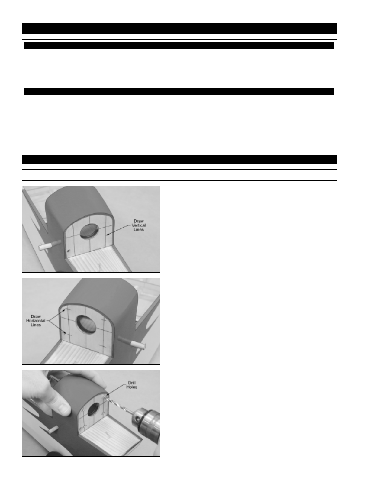
SECTION 23: ELECTRIC MOTOR, ESC AND BATTERY INSTALLATION
YOU'LL NEED THE FOLLOWING PARTS FROM THE KIT:
❑ (2) Engine Mounting Beams
❑ (4) M3 x 18mm Machine Screws
❑ (4) Motor Mounting Straps
❑ (4) M3 x 12mm Wood Screws
YOU'LL NEED THE FOLLOWING TOOLS AND SUPPLIES:
❑ Kwik Bond 5 Minute Epoxy
❑ # 2 Phillips Head Screwdriver
❑ Electric Drill
❑ 3/32" & 5/32" Drill Bits
❑ Ernst Airplane Stand
❑ Ruler
STEP 1: INSTALLING THE MOTOR MOUNTING BEAMS
✦✦
✦IMPORTANT
✦✦
✦✦
✦ To aid in alignment, the horizontal and vertical thrust lines have been predrawn onto the firewall for you.
✦✦
❑ (8) M3 Flat Washers
❑ (4) M3 Blind Nuts
❑ (2) Plywood Mounting Plates
❑ Pencil
❑ Paper Towels
❑ Rubbing Alcohol
❑ NHP Epoxy Mixing Sticks
❑ NHP Epoxy Mixing Cups
❑ Using a ruler and a pencil, measure out 13/16" and draw one vertical
line to the right of the vertical thrust line and one vertical line to the left of
the vertical thrust line.
Make sure that the two vertical lines you draw are parallel to the
☞
vertical thrust line.
❑ Using a ruler and a pencil, measure and draw a horizontal line 1/2"
above the horizontal thrust line, then measure and draw a horizontal
line 13/16" below the horizontal thrust line.
Again, make sure that the two horizontal lines you draw are parallel
☞
to the horizontal thrust line.
❑ Using a drill with a 5/32" diameter drill bit, drill a hole through the
firewall at each of the four intersecting lines.
38
Continued On Next Page
☛☛
☛
☛☛
Page 39
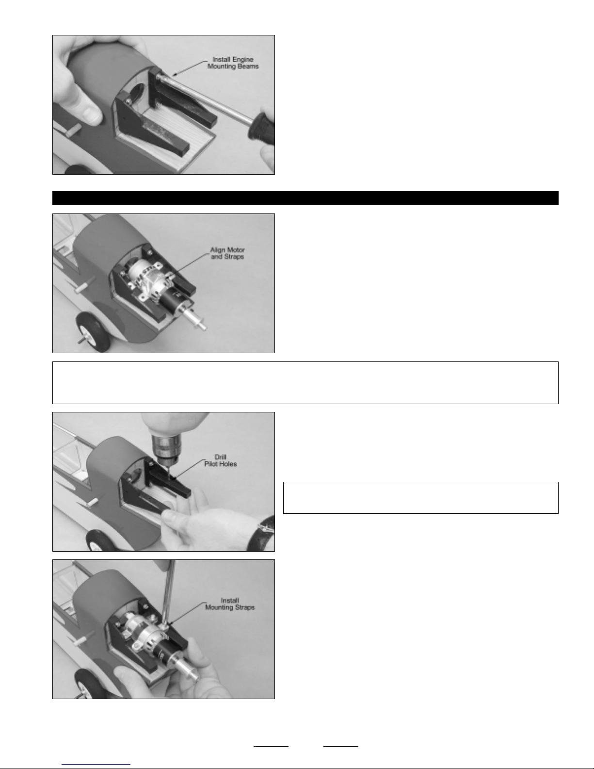
STEP 2: INSTALLING THE MOTOR
❑ Install the two engine mounting beams onto the firewall, using four
M3 x 18mm machine screws, four M3 flat washers and four M3 blind
nuts. Tighten the screws firmly to draw the blind nuts into the back of
the firewall.
Note that the engine mounting beam with a notch in it is mounted
☞
on the right side of the firewall.
❑ Install the propeller adapter that you purchased separately onto
your motor.
❑ Set the two lower motor mounting straps (the deeper of the four)
onto the engine mounting beams, then set your motor onto the straps.
❑ Position the straps and your motor so that your propeller adapter is
about 3-7/8" from the front of the firewall.
❑ When satisfied with the alignment, use a pencil to mark the locations
of the mounting holes onto the engine mounting beams.
✦✦
✦IMPORTANT
✦✦
the motor forward or back slightly it won't cause any problem. We'd suggest mounting the motor further forward than back,
though, to help balance the airplane.
✦✦
✦ The 3-7/8" measurement is not set in stone. Frankly, for this airplane, it's not very critical. If you need to move
✦✦
❑ Remove the motor and mounting straps, and drill 3/32" diameter
pilot holes through the engine mounting beams at the marks you drew.
✦✦
✦IMPORTANT
✦✦
and not at an angle.
❑ Set the motor mounting straps and your motor back into place and
realign them.
❑ Place the remaining two motor mounting straps over the motor and
secure the assembly into place, using four M3 x 12mm wood screws
and four M3 flat washers.
✦✦
✦ Be careful that you drill the holes straight down
✦✦
Now that you've got your motor installed, please turn back to Section 15 on page # 29 to finish the assembly of your
Speedy Bee ARF. When you get to Section 18 on page # 34, turn back to the next page to install your ESC and flight battery.
Tighten the screws firmly, yet evenly, to hold the motor securely in
☞
place.
39
Continued On Next Page
☛☛
☛
☛☛
Page 40

STEP 3: INSTALLING THE ESC
❑ If your ESC and motor do not use compatible connectors that can be plugged into each other, carefully solder the motor wires
to the motor wires on your ESC, being careful that the polarity is correct. Make sure to use heat-shrink tubing to insulate the
solder joints.
❑ Install your ESC into the fuselage as far forward as possible. Use a piece of double-sided tape or Velcro to hold the ESC
firmly in place.
✦✦
✦IMPORTANT
✦✦
❑ If your ESC features a micro switch, mount it in a convenient place on the side of the fuselage.
STEP 4: INSTALLING THE FLIGHT BATTERY
If you are using a LiPO flight battery, the LiPO flight battery that you choose MUST be able to handle the current draw
of your motor, gear box and propeller combination. Before charging or otherwise using your LiPO battery pack, please
read all warnings included with it.
Smaller capacity LiPO flight batteries may be too light to balance the airplane properly. In this case, it may be necessary
to add some nose weight.
❑ Install your flight battery into the fuselage using your favorite method to secure it into place. You will need to mount your flight
battery in the best location to balance the airplane. We have included two plywood plates that can be cut to length and glued
between the fuselage sides to mount your flight battery to.
❑ After installing your flight battery, complete step # 1 on page # 34 to install the hatch cover. You can then continue with mounting
your receiver and balancing the airplane.
✦✦
✦ Mount the ESC as far forward as conveniently possible to help balance the airplane.
✦✦
40
Page 41

41
Page 42

42
Page 43
PRODUCT EVALUATION SHEET
Telling us what you like and don't like determines what model kits we make and how we make them. We would appreciate it if you would
take a few minutes of your time to answer the following questions about this kit and your modeling interests. Simply fold this form on the
dotted lines, seal with tape and mail it to us. Do not use staples and make sure our address faces out.
Global Hobby Distributors will not disclose the information it collects to outside parties. Global Hobby Distributors does not sell,
trade, or rent your personal information to others. Your privacy is important to us.
1) Kit: Clancy Aviation Speedy Bee ARF # 222210
2) Where did you learn about this kit?
❑ Magazine Ads ❑ Friend
❑ Hobby Shop ❑ Other
❑ Internet
3) What influenced you the most to buy this kit?
❑ Magazine Ads ❑ Price
❑ Type of Model ❑ Box Art
❑ Recommendation ❑ Other
❑ Internet
4) Did you have any trouble understanding the written
instructions? If yes, please explain.
❑ Yes ❑ No
____________________________________
____________________________________
____________________________________
____________________________________
5) Did you have any trouble understanding any of the
photographs? If yes, please explain.
❑ Yes ❑ No
____________________________________
____________________________________
____________________________________
6) Were any of the kit parts:
Cut Along Dotted Line
❑ Damaged ❑ Wrong Size
❑ Missing ❑ Wrong Shape
If you checked any of the boxes above, did you
contact our Customer Service Department to resolve
the problem?
❑ Yes ❑ No
7) Was any of the assembly difficult for you? If yes,
please explain.
❑ Yes ❑ No
____________________________________
____________________________________
____________________________________
____________________________________
8) What did you like most about this kit?
❑ Assembly Manual ❑ Parts Fit
❑ Hardware Supplied ❑ Price
❑ Other
____________________________________
____________________________________
____________________________________
9) What did you like least about this kit?
❑ Assembly Manual ❑ Parts Fit
❑ Hardware Supplied ❑ Price
❑ Other
____________________________________
____________________________________
____________________________________
10) Are you satisfied with the finished model? If no,
please explain.
❑ Yes ❑ No
____________________________________
____________________________________
____________________________________
____________________________________
11) How does this kit compare to similar kits by other
manufacturers?
❑ Better ❑ As Good
What is Your Age Group:
❑ 10 & Under ❑ 11 - 20 ❑ 21 - 30 ❑ 31 - 40 ❑ 41 - 50 ❑ 51 - 60 ❑ 61 - 70 ❑ 71 +
How Many Years Have You Been in the Hobby?
❑ Less than 1 ❑ 2 - 4 ❑ 5 - 7 ❑ 8 - 10 ❑ 11 - 15 ❑ 16 - 20 ❑ 20 or More
How Many Models Have You Purchased In the Last Year?
❑ 0 - 1 ❑ 2 - 4 ❑ 5 - 7 ❑ 8 - 10 ❑ 10 or More
Please List any Other Modeling Interests or any Additional Information about This Product: ______________________
_____________________________________________________________________________________
_____________________________________________________________________________________
_____________________________________________________________________________________
_____________________________________________________________________________________
All contents copyright © 2005, Global Hobby Distributors Version V1.0 February 2005
43
Page 44

_____________________________
_____________________________
_____________________________
(Return Address Here)
Global Hobby Distributors
Attn: Global Services
18480 Bandilier Circle
Fountain Valley CA 92728-8610
Fold along dotted line
Fold along dotted line
Post Office will
not deliver
without proper
postage
44
 Loading...