

Clairvoyant C2110H User Manual

H.264MP RTSP Streaming User’s Manual
1
H.264 Main Profile RTSP Streaming
Stand Alone
IP Camera/Video Server
MANUAL
Firmware 2.2.1.3 Version
Revision Date : 2010.04.01
WARNING: If the actions indicated in a “WARNING” are not complied with, injury
H.264MP RTSP Streaming User’s Manual
2
or major equipment damage could result. A warning statement typically describes the hazard,
its possible effect, and the measures that must be taken to reduce the hazard.
CAUTION: If the action specified in the “CAUTION” is not complied with, damage
to your equipment could result.
NOTE: A “NOTE” provides supplementary information, emphasizes a point or procedure, or
gives a tip for easier operation.
CAUTION:
Any changes or modifications not expressly approved by the party responsible for
compliance could void the user’s authority to operate the equipment.
NOTE: This equipment has been tested and found to comply with the limits for a class digital device, pursuant
to part 15 of the FCC Rules. These limits are designed to provide reasonable protection against harmful
interference when the equipment is operated in a commercial environment. This equipment generates, uses,
and can radiate radio frequency energy and, if not installed and used in accordance with the instruction manual,
may cause harmful interference to radio communications. Operation of this equipment in a residential area is
likely to cause harmful interference in which case the user will be required to correct the interference at his own
expense.
Disposal of Old Electrical & Electronic Equipment
(Applicable in the European Union and other European countries with separate
collection systems)
This symbol on the product or on its packaging indicates that this product shall not be treated as
household waste. Instead it shall be handed over to the applicable collection point for the recycling of
electrical and electronic equipment. By ensuring this product is disposed of correctly, you will help prevent
potential negative consequences for the environment and human health, which could otherwise be caused
by inappropriate waste handling of this product. The recycling of materials will help to conserve natural
resources. For more detailed information about recycling of this product, please contact your local city
office, your household waste disposal service or the shop where you purchased the product.

H.264MP RTSP Streaming User’s Manual
3
• Make sure not to connect the power before you install the camera.
• There is great chance of damaging your camera if the camera is opened by an unqualified
service engineer or installer.
• Avoid using the camera under direct sunlight (tropical area, Middle East), or near to any
source of heat.
• Don’t merge the camera under water; always put silicon gel on antenna connector after
installation to avoid corrosion and reducing the wireless link capability.
• Avoid exposing the camera to violent movement or vibration.
• Always use the camera in a well ventilated location to prevent overheating.
• Connect proper “Relay” between load and camera, to protect camera, don’t connect load
greater than 0.5A.
• Please use power adapter equipped with the camera, foreign power adapter with wrong
voltage may permanent damage your camera.
• Wireless link distance is depend on both camera (Wi-Fi client) and Access Point,
unbalanced transmit power won’t help extend the wireless link range.
• Clean the glass window frequently to ensure good clear view, remove the snow and ice
accumulated outside and inside of class window shield, keep camera inside dry by blow
dryer.
• Must use PSE come with POE camera
All the safety and operating instructions must be read before the unit is operated.

H.264MP RTSP Streaming User’s Manual
4
Table of Contents
Chapter 1 Features ................................................................................................................... 5
Chapter 2 Packing Detail .......................................................................................................... 8
Chapter 3 Cable and Connectors .............................................................................................. 9
3.1 FRONT VIEW .................................................................................................................................... 9
3.2 REAR VIEW .................................................................................................................................... 12
Chapter 4 System Requirement .............................................................................................. 15
4.1 The lowest hardware configuration .................................................................................................. 15
4.2 The recommended hardware configuration ..................................................................................... 15
Chapter 5 INSTALLATION ...................................................................................................... 16
5.1 CONNECT to PC or LAN .............................................................................................................. 16
5.2 CONNECT to WAN ....................................................................................................................... 21
5.3 Install ActiveX and Login ............................................................................................................... 22
Chapter 6 Software Configurations ......................................................................................... 28
6.1 Menu Tree ..................................................................................................................................... 28
6.2 Live View Page ............................................................................................................................. 29
6.3 Video Playback ............................................................................................................................. 33
6.4 System Settings ............................................................................................................................ 35
6.5 Video Settings ............................................................................................................................... 37
6.6 Motion Alarm Setting ..................................................................................................................... 39
6.7 Sensor Alarm Settings .................................................................................................................. 40
6.8 Network Setting ............................................................................................................................. 42
6.9 Advanced Settings ........................................................................................................................ 45
6.10 User Management .........................................................................................................
............. 48
6.11 RS-485 Settings .......................................................................................................................... 49
6.12 Storage Settings .......................................................................................................................... 50
6.13 Local Settings ............................................................................................................................. 54
Appendix 1 Network Port for IP Camera ................................................................................. 55
Appendix 2 Network Factory Defaults ..................................................................................... 55
Appendix 3 DDNS introduction ............................................................................................... 55
Appendix 4 FAQ ...................................................................................................................... 58
Appendix 5 Cross Ethernet Cable Making Tip ........................................................................ 62

H.264MP RTSP Streaming User’s Manual
5
Chapter 1 Features
H.264 Main Profile Encoding, Duplex Audio
Optional Wi-Fi, POE & Hi Power IR LEDs
Clairvoyant IP Cameras/ Video Servers offer cost-effective, indoor/ outdoor (Wi-Fi) IP
surveillance solution for remote monitoring and stand alone alarming over a local area
network or the Internet. Optional POE makes the wiring easier, only standard UTP Cat. 6
Ethernet cable required carrying both data and DC 48V power, no extra electric cable
required, Clairvoyant IP Cameras/ Video Servers are ideal for use in small or mid-sized
businesses and homes, it is also easy to set up and use.
Clairvoyant IP Cameras/ Video Servers are embedded IP based smart devices designed for
(2.4GHz wireless) network video/audio surveillance applications. Optimized H.264 video
compression algorithm assures clearer and more fluent image transmission. Clairvoyant IP
Cameras adopt 420 TVL 1/3” Sony CCD (optional 480TVL/ 550TVL), the latest technology
and high integration single chip SOC with powerful Linux RTOS (Real-time Operating System)
to realize high performance and low cost digital multimedia processing. Built-in Web Server
allows users to conveniently carry out remote control via Internet Explorer. Furthermore,
central management software can be used for integrated surveillance and management of
multiple Clairvoyant IP Cameras/ Video Servers, very easy to build large surveillance
system.
Performance:
- SOC single chip solution, equipped with two processors, ARM9 and DSP
- Support high sensitivity CCD sensor (IP Cameras) or analog video input (Video Server)
- H.264 main profile @ Level 3, realize transmission of High Definition video over low
network bandwidth easily.
- Support dual compression and dual video streams, more adaptive to different network
environment, display different resolution video on different client devices (PC & phone)
- Up to 30 frames per second in all resolutions ranging up to 704 x 576
- Up to 10 viewers can directly access the camera simultaneously
- Stand alone alarming & motion detection; able to set 4 detective zones each with 5 levels
sensitivity, send snapshots by scheduling or at alarm/ motion detected through emails or
upload pictures to FTP server.
- Built-in Web server enables the use of a standard Web browser for viewing and
management
- Support remote software upgrade safely function
- Support dynamic IP address (DDNS), LAN, Internet (ADSL PPPoE & DHCP)
- Network protocols: HTTP, TCP/IP, UDP, RTP, RTCP, RTSP, SMTP, PPPoE, DDNS, DNS,
SMTP, BOOTP, DHCP, FTP, NTP
- Support Bi-directional real time transmission of audio talk-back & broadcast.
- Network self-adapting technology to adjust video frame rate automatically according to the
network bandwidth.
- Auto-recovery function if exception occurs and auto-connection if the network fails
- Provide SDK and client demo source code.
- Management software that can manage up to 1728 cameras in 48 groups, display
maximum 36 cameras video on single screen, support video lost、motion detection and

H.264MP RTSP Streaming User’s Manual
6
sensors alarm functions
- Support masks function to mask sensitive area to protect privacy.
- Support active & passive mode access, support GSM/ CDMA network or private network
without public IP.
- Support Multicast, unlimited clients connection. (match with Clairvoyant decoder or
NVSCenter software)
- Supports SD card up to 32GB; can store recording and snapshots locally.
- Optional POE-PD & PSE
- Optional IEEE 802.11g/b client (2.4GHz)
- Optional IP64 Weather proof
- Optional 35 high efficiency IR LEDs
Technical parameters:
Imagine Sensor: 420 TVL, 1/3 Sony CCD, Day/ Night, optional 480TVL/ 550TVL
Lens: 6mm fixed focal, optional 4/ 8/ 12/ 16/ 25 mm
Day/ Night: Outdoor bullet IP Camera: Hi-Power IR LEDs, effective range 40 meters (35 x
Ø8mm IR LEDs, 60°)
Indoor dome IP Camera: IR LEDs, effective range 15 meters (18 x Ø5mm IR LEDs, 60°)
Video compression: H.264 main profile @Level 3; M-JPEG dual compression
Video Resolution: PAL: 352x288(CIF),704x288(2CIF),704x576(D1)
NTSC: 352x240(CIF),704x240(2CIF, 704x480(D1)
Adjustment of Video Parameters: Brightness, hue, contrast, saturation and image quality
Streaming Format: Optional streaming format (video streaming or audio & video streaming)
Video Frame Rate: PAL: 1 - 25 frames/second; NTSC: 1 - 30 frames/second
Video Compression Bit Rate: 16Kbit/S~16Mbit/S, constant bit rate or variable bit rate
Audio Input: 1 channel linear input, Impedance: 1kΩ
Audio Compression: MP3
Audio Output: 1 channel linear output
Audio talk-back input: 1 channel, MIC interface
Supported Protocols: HTTP, TCP/IP, UDP, RTP, RTCP, RTSP, SMTP, PPPoE, DDNS,
DNS, SMTP, BOOTP, DHCP, FTP, NTP
System Interface: 10 Base-T/100Base-TX Ethernet port; 1 RS485 port, 1 RS232 port;
Optional Wi-Fi: 2.4GHz, IEEE 802.11g/b with WEP, WPA, WPA2
Antenna (optional)
- 5dBi @2.4GHz, Omni
- IPEX1.13
Alarm Input: 1 channel on/off input, supporting NO (normally open) or NC (normally close)
Alarm Output: 1 channel on/off output, Contact rating 220VAC 1A/ 24VDC 1A
Dimensions (mm, L x H x W):
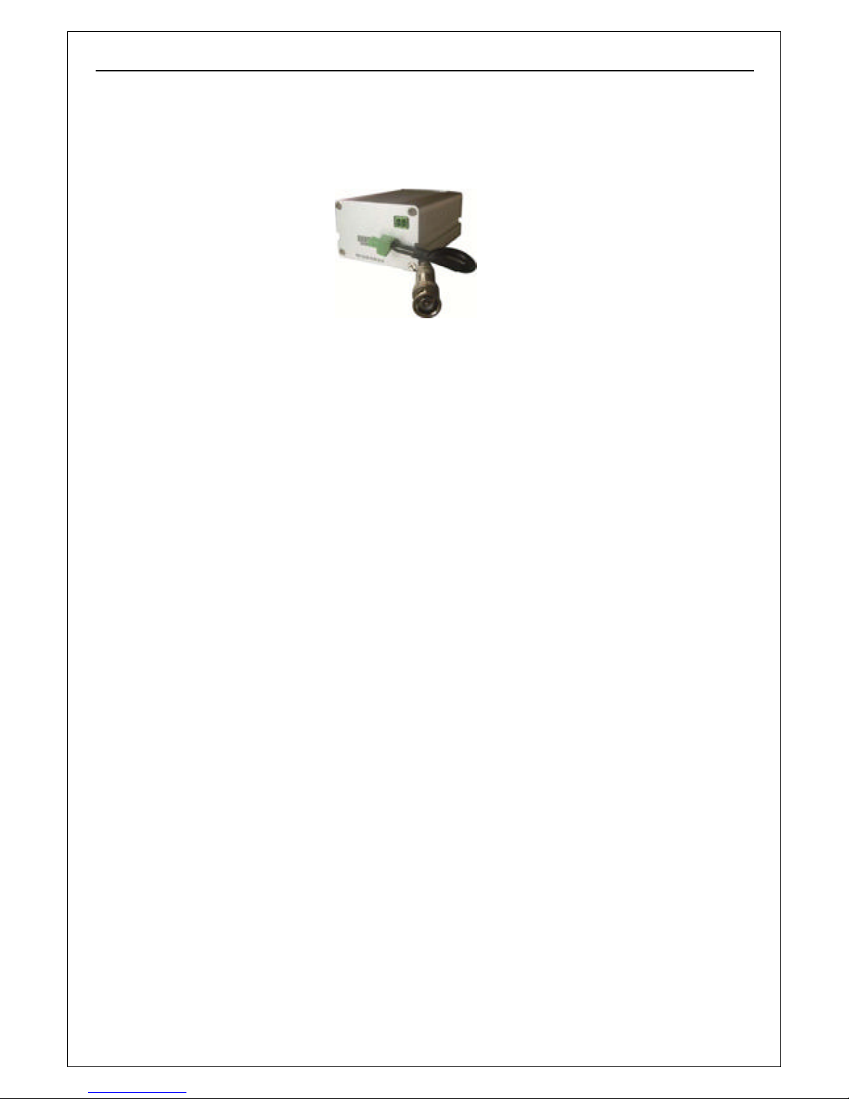
Video Server: 103 x 70 x 45
Outdoor bullet IP Camera: 260 x 115 x 100;
Indoor dome IP Camera: Diameter: 130, Height: 105
Weight (g):
Video Server: 400
Outdoor bullet IP Camera: 950;
Indoor dome IP Camera: 750

H.264MP RTSP Streaming User’s Manual
7
Input Power Supply: Optional POE-PSE
Maximum Power: Less than 8W, optional DC 48V POE-PD
Operating Temperature: -10 ~ +55 ℃
Storage Temperature: -20 ~ +70 ℃
Weather Proof: IP64 (Outdoor bullet IP Camera)
System Requirements:
Operation System:
Microsoft Windows XP, VISTA, Windows 7
Browser:
Microsoft Internet Explorer 6.x or above
H.264MP RTSP Streaming User’s Manual
8
Chapter 2 Packing Detail
1. IP Camera (optional Wi-Fi or POE)
2. Installation Software utilities & Central Management Software CD
3. AC Adaptor (DC12V/ 2A) & Power Cord
3. AC Adaptor & Power Cord
1. IP Camera/ Video Server
2. Installation Software utilities CD

H.264MP RTSP Streaming User’s Manual
9
Chapter 3 Cable and Connectors
3.1 FRONT VIEW
1. Terminal (A+/ B-) : RS-485 A+/ B-; D+/ D- to control PTZ
2. Reset Terminal : Restore to factory default settings
3. RCA connector : Female audio output to speaker
4. Power connector : DC12V/ 2A
5. RCA plug: Male audio input port to sound monitor/ microphone.
6.
Terminals (Alarm) : Alarm input (NC or NO) /
Alarm output (on/off output, 220VAC 1A/ 24VDC 1A)
7. RJ-45 : Network Ethernet connector, LEDs flashing when accessing
○
1
○
3
○
5
○6
○
4
○
2
○
7

H.264MP RTSP Streaming User’s Manual
10

H.264MP RTSP Streaming User’s Manual
11
There is RCA male plug on tail wire, connect it to RCA female connector of "amplified
microphone".
We provided a splitter wires with one power connector and two power plugs that can split
power from DC 12V power adapter to supply DC 12V power to camera and the microphone.

H.264MP RTSP Streaming User’s Manual
12
3.2 REAR VIEW
Port Name Description
○
1
RSMA Connector
5 dBi omni antenna
○2 Tail Cable
3 feet wire
Connect BNC output to monitors
○
1
○
2

H.264MP RTSP Streaming User’s Manual
13
RS-485 port can be used to connect the external PAN/ TILT Seat
Connect Pan/ Tilt Seat D+, D- : Connect PT control line (485A, 485B terminal)
Alarm input:
Connect sensors that support on/off states change.
To connect the Active Infrared Sensor to IP CAMERAR camera ALARM IN, will trigger alarm
when light beams interrupted.
No DESCRIPTION
1 485A(TX+) RS485:Transmit data
2 485B(TX-) RS485: Receive data

H.264MP RTSP Streaming User’s Manual
14
Alarm output:
WARNING: If connect higher power loading (> 1A) directly to camera alarm out
will cause damage the camera.
Higher current (>0.5A) will accelerate aging of the relay on camera PCB,
external relay box is always recommended to protect the camera.

H.264MP RTSP Streaming User’s Manual
15
Chapter 4 System Requirement
4.1 The lowest hardware configuration
.
◆CPU: Intel Pentium 2.0GHz (Don’t support AMD CPU)
◆Memory:1,024MB
◆Graphics Card: TNT2
◆Sound Card: Speaker, Microphone
◆Hard Disk: Recording Image,no less than 40G
4.2 The recommended hardware configuration
.
◆CPU: Intel Core2 DUAL 2.0GMhz or above
◆Memory: 2,048MB
◆Graphics Card: Nvidia Geforce FX9400 or ATI RADEON 9000 series 256MB video
memory, graphic card supports hardware Scaling
The PC graphics card must support hardware zoom in & out.
Tested Graphics Cards are as follow:
• Nvidia TNT/ TNT2,
• Geforce GTX295/285; Fx 8800/ 9600/ 9800 and its series;
• ATI Radeon 7000/7200/7500/8500/9550/9600/9700/9800 and X & HD series,
• Matrox G450/ 550;
• INTEL 865G/ 875G and its series.
Operation System
◆Chinese; English: Windows2000/ Windows XP/ Windows Vista/ Windows 7.
Software
◆IE 6.0 or above
◆DirectX 8.0 or above
◆TCP/IP protocol
H.264MP RTSP Streaming User’s Manual
16
Chapter 5 INSTALLATION
5.1 CONNECT to PC or LAN
CAUTION:
Please use the DC power adapter that is provided with the camera.
Connecting camera to other power source will cause permanent damage
to the camera.
NOTE:
Please use straight Ethernet cable (CAT. 5e) to connect camera to your home/ office
network switch/ hub or a broadband router.
For Wi-Fi models, you will still need to connect camera to your PC by Ethernet cable at
first time installation, correct SSID, WEP/ WPA password & IP address must be set
before you can connect the camera wirelessly (See more in section 6.8 Network
Settings).
You will see two IP address by camera search software utility, if you didn’t remove the
Ethernet cable before the camera wireless connection.
Click “Search Camera” on Utility CD auto-play menu*, will find all the
Clairvoyant IP cameras in

H.264MP RTSP Streaming User’s Manual
17
your local network.
* To use SearchNVS software to search and modify network parameters (IP address, Subnet
mask, Gateway etc.).
NOTE:
A: Find the SearchNVS.exe in 【tool software】 folder of Utility CD and copy it to PC.
B: Install the Central Management software first, follow below steps to find the SearchNVS:
【Start】---【all programs】--- 【NVS Center500】---【Search NVS】.
The factory default settings of the IP Camera are as follows
IP: 192.168.55.160; Subnet mask: 255.255.255.0
User name: admin; Password: admin
Run the SearchNVS software to search and modify IP Camera network parameters.
SearchNVS use multicast protocol to find Clairvoyant IP cameras; most firewalls forbid the
multicast data packets. So please close the firewall first or enable/ allow SearchNVS to use
multicast protocol.
Click on【Search】button to start search IP Cameras as illustrated below:
【Local IP 】Display the local PC IP. If your PC has multiple NICs or multi-addressed local IP,
please select an IP address to connect NVS.
In the above Search NVS software interface, it shows this computer has searched all IP
Cameras in LAN. If there are many IP cameras in your LAN, you can distinguish which
camera is yours by the Device Name based on the unique device ID. The Device Name
was named in the factory as “DVS+ID number”.
Note:
Please make sure there is DHCP server available, or set your PC IP address
manually. Your PC won’t “Obtain an IP address automatically” without DHCP connected.
SearchNVS won’t work on a PC without IP address.
Please select the correct Network Interface Card (that connected to cameras) IP address
for “Local IP” if you have multiple Network Interface Cards installed in your PC.
Set IP address for IP camera.
Your computer IP address must be “in the same subnet” of IP Camera in order to visit
IP camera. So we need to set the IP address of the IP camera before accessing
camera.
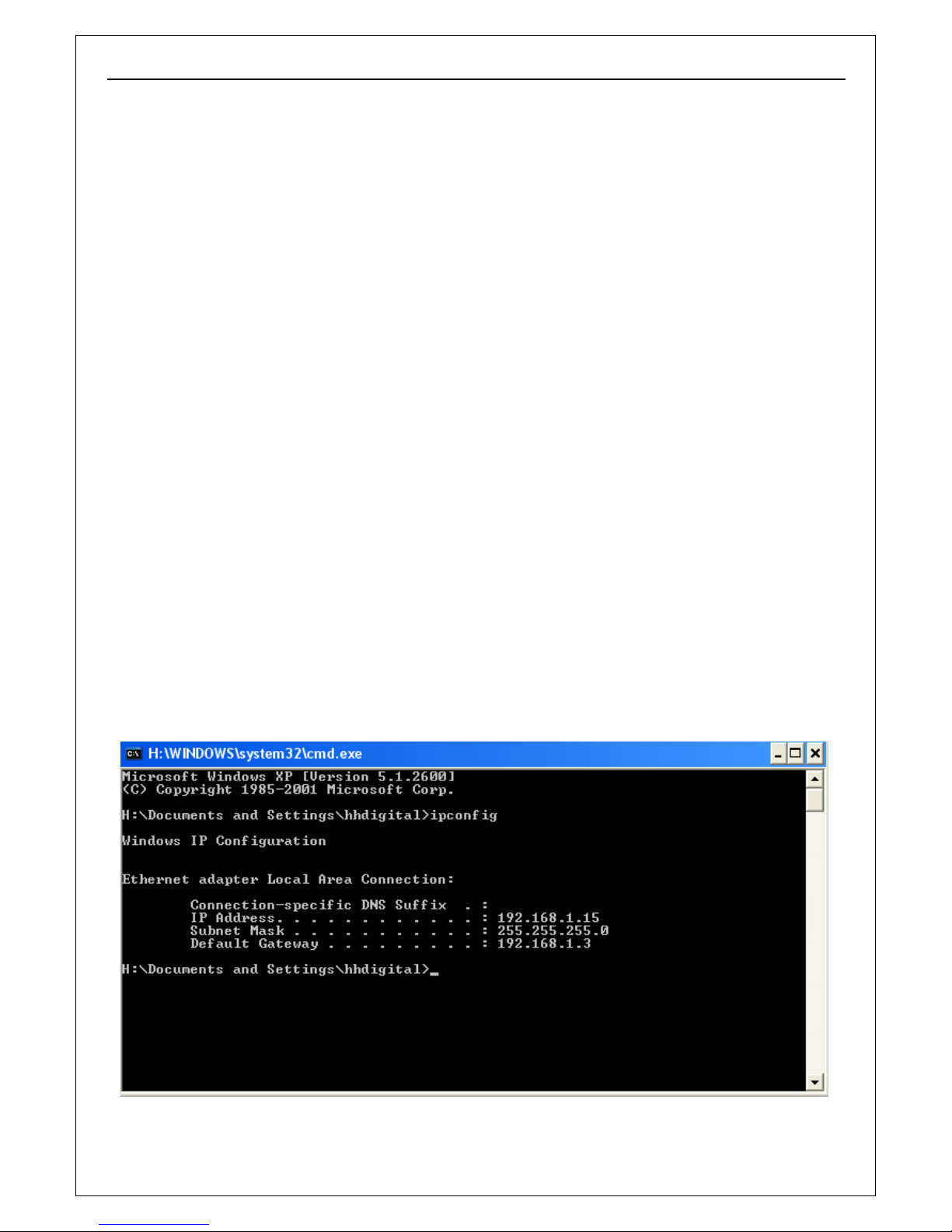
To get your PC IP configuration information: go to command mode by click 【Start】
【Run】”, then input “command” or “cmd”(Windows 2000/XP system).click “ok”:
H.264MP RTSP Streaming User’s Manual
18
Type “ipconfig” at command prompt”, press “Enter” button, you will get your PC
Network Interface Card IP address/ Subnet mask/ Ga teway information.

H.264MP RTSP Streaming User’s Manual
19
Please remember the IP Address,Subnet Mask, Default Gateway,then setup the IP Camera
IP address according to your PC IP address to ensure computer & IP Camera IP
addresses are “in the same subnet” .
For example: Set IP Camera IP addresses to 192.168.1.100. Default Gateway & Subnet
Mask same as PC.
Click 【 Set】 to set “Network Parameter” as illustrated below:
Modify relative Network Parameters; click “OK”, then the IP camera will reboot.
Test the IP camera connection: go to command mode by click 【Start】---【Run】”, then
input “command” or “cmd” (Windows 2000/XP system).click “ok”,
Type “ping 192.168.1.100” at command prompt, press “Ent er” button, you will get following
information:
The message shown on above indicates the IP Camera is functioning normally and connects to
 Loading...