

Page 1
User’s manual
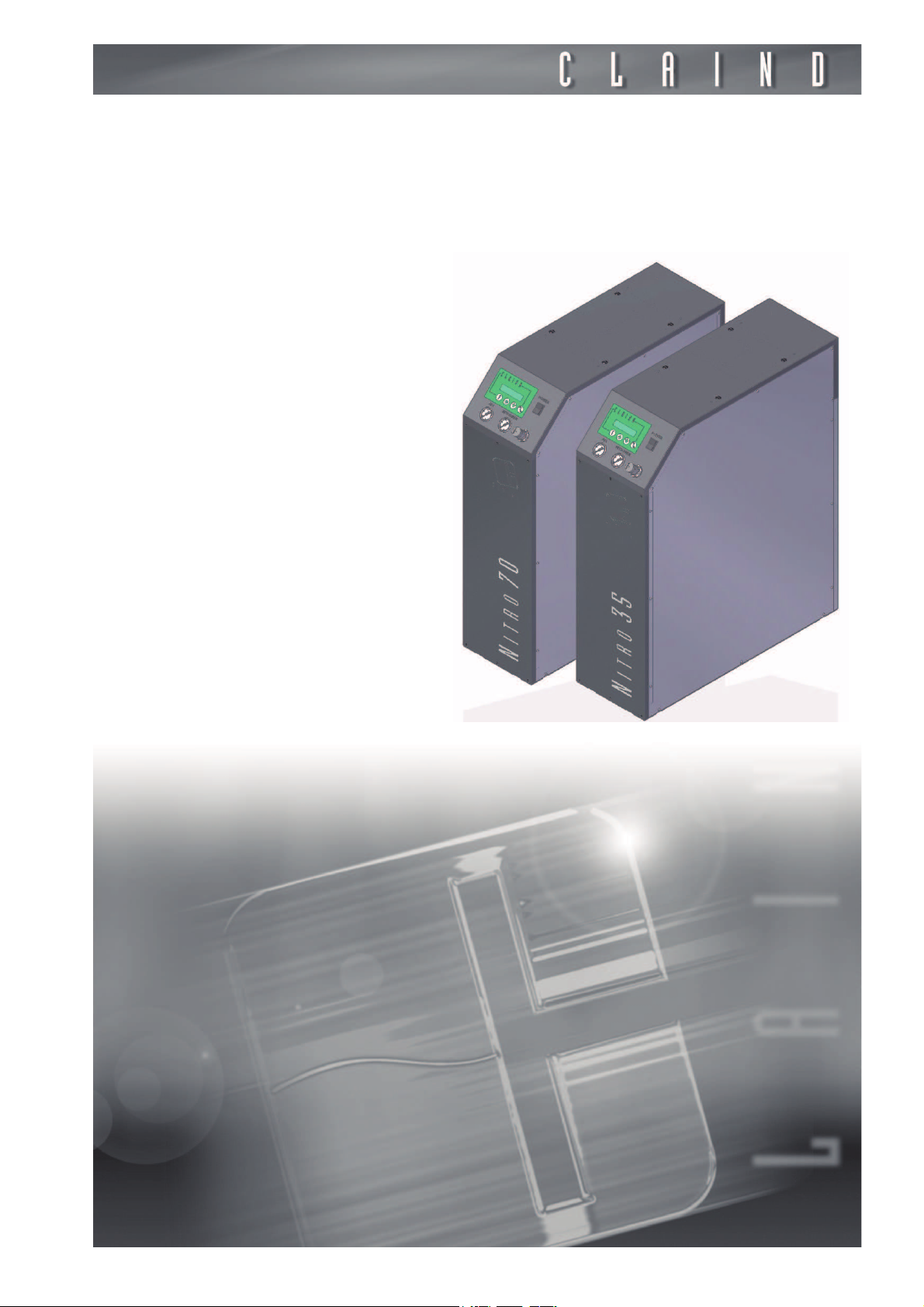
Nitrogen
Generators
Nitro35
Nitro70
Page 2
Table of contents
1. Introduction 3
2. Safety 4
3. Description of the generator 6
4. Installation 9
5. Disassembly and transport 17
6. Use 18
7. Maintenance 24
8. Troubleshooting 26
9. Guarantee 27
10. Declaration of conformity 28
11. Notes 29
2
Page 3

Nitrogen Generators Nitro35 Nitro70
1.
Introduction
This document is intended for users of Nitrogen generators model Nitro35 and
Nitro70 and provides all information regarding installation, use, maintenance,
and guarantee.
With regard to installation and maintenance, it is presumed that the user is experienced in the use of pneumatic components, and in particular is aware of all safety aspects linked to the use of compressed air and nitrogen.
The margin of the text contains the following symbols, indicating:
m
c
e
compulsory safety standards to be observed
electrical hazard
recommendations and important information
It is strongly recommended to carefully read all safety warnings (
before carrying out any operation on the generator.
par. 2.1.
)
3
Page 4

Safety
2.
Safety
These generators can be installed next to the users without having to classify
the nearby area as “dangerous”, since it has been designed with all the necessary precautions to guarantee maximum safety.
e
e
2.1.
m
m
c
The unit must be installed and used in observance of the instructions in this
booklet. Furthermore, use of the generator must be limited to that described in
Chapter 1 Introduction
guarantee null and void and release CLAIND from all liability for direct or indirect
damage or physical injury.
The user is responsible for asking local authorities if there are local safety
regulations that are stricter than what is described in this manual.
. Failure to observe the foregoing will render the
Warnings
Place the generators FAR FROM SOURCES OF HEAT
Place the generators in an environment PROTECTED AGAINST RAIN
AND WIND
NEVER OPEN the generator while it is connected to the electrical
mains: RISK OF FATAL INJURY BY ELECTROCUTION
e
e
2.2.
Repairs and inspections must be carried out exclusively by QUALIFIED
PERSONNEL: in the event of faults which cannot be resolved according to the
procedures listed in the TROUBLESHOOTING chapter, contact exclusively our
authorized Technical Assistance.
If the generator has not to be used for a prolonged period of time, it must be
depressurised (par. 6.5.)
Consideration on the use of nitrogen
Nitrogen isn’t a toxic gas, but when the percentual content of the air exceed determinated values suffucation risk can occur.
We recommend therefore to not breath the gas directly and not to work in the
nearby of the Nitrogen flux.
Due to the low quantities of Nitrogen produced, a normally ventilated enviroment is anyway sufficient to prevent the accumulation risk.
4
Page 5

Nitrogen Generators Nitro35 Nitro70
2.3.
m
2.4.
e
Safety devices
MAXIMUM PRESSURE:
The maximum applicable compressed air pressure to generators is 10 bar. Please pay attention that this value doesn’t exceed in order to avoid explosion risk
due to the structural failure of the components.
Pressure in the built-in reservoir is limited by a safety valve.
Technical assistance
CLAIND disclaims any liability for any damages caused from improper use of the
generator.
Please contact CLAIND Service center before of any kind of intervention.
CLAIND technical assistance can be contacted as follows:
Phone ++39 0344 56603
Fax ++39 0344 56627
e-mail: [email protected]
5
Page 6

Description of the generator
3.
Description of the generator
3.1.
3.2.
3.2.1.
Equipment supplied
Unless differently agreed, the supply includes:
• n°1 Nitrogen generator model Nitro35 or Nitro70;
• n°1 certificate of conformity of tank and safety valve, that you can found inside
the generator;
• n°1 cable for the electrical mains;
• n°2 male fitting for plastic tube external diameter=10mm;
• n°1 CD user’s manual;
• n°2 eyebolts for lifting the generator;
• n°4 feet;
• n°4 stabilizer brackets;
• n°8 screw diameter 6mm, lenght 20mm;
• n°8 washers.
Technical specifications
General requirements
Dimensions Width 26,5 cm
Depth 75 cm
Height 92 cm
Weight of Nitro35 75 kg
Weight of Nitro70 90 kg
Packing dimensions Width 80 cm
Depth 120 cm
Height 115 cm
Gross weight of Nitro35 95 kg
Gross weight of Nitro70 110 kg
Noise (1m from the front panel) 50 dBA*
Working temperature from 5°C to 40°C
Protection rating IP20
* with the exception of a peak of 63 dBA for second every minute.
6
Page 7

Nitrogen Generators Nitro35 Nitro70
3.2.2.
3.2.3.
Electrical requiremets
Supply voltage 230 V~ (±10%); 1ph; 50Hz
Nominal power 30 W
Gas
Flow rate and purity degree of nitrogen outlet vary depending on the kind of utilization and of application. The technical specification of this model are indicated
on the related product sheet.
7
Page 8

Description of the generator
E
C
A
D B
C D
A B
3.3.
3.3.1.
3.3.2.
Generator components
Frontal view
A. ALPHANUMERIC DISPLAY AND
KEYPAD: they indicate the alarm and
operative condition; the four keys
allow to display and set the working
parameters.
B. NITROGEN GAUGE: it indicates the
outlet Nitrogen pressure
C. “POWER” KEY: it is the power switch.
D. AIR GAUGE: it indicates the
compressed ari pressure of the intake
line of the generator
E. PRESSURE REGULATOR: it allows to
set the outlet Nitrogen pressure
Rear view
A. LABEL: it shows the identificative data
of the generator and the power supply
data.
B. CONNECTORS for the power supply
cable; it includes the main FUSE
lodging, whose characteristics are
indicated in the “F” label.
C. NITROGEN: pneumatic connection
(G 1/4’’ female) for nitrogen line to be
connected to the user.
D. AIR: pneumatic connector for
compressed air line (G 1/4’’ female)
8
Page 9

Nitrogen Generators Nitro35 Nitro70
4.
Installation
4.1.
4.1.1.
4.1.2.
4.2.
4.2.1.
Installation preparation guide
Moisture and particulate
In order to avoid damages to the electronic components, we recommend to install the generator in a area where the relative moisture and the dust concentration are limited.
Moreover, the generator must be protected from dripping, rain and wind.
Temperature
Environmental temperature of the area of the installation must be between 5°c
and 40°c.
Please avoid proximity to heat sources. Please avoid the direct exposition to sun
beams.
Generator positioning
Handling
m
e
4.2.2.
The packed generator can be handled using an adequate instrumentation, such
as a transpallet or a fork lift. Once unpacked, it can be moved by his own wheels.
If suddenly moved the generator could fall and generate damage to
things or persons.
The generator must be always kept in vertical position since it has not been designed to be layed down.
Unpacking
The generator is shipped on a dedicated pallet.
Please remove packing paying attention not to damage the panels of the generator.
When possible, please keep the original packing to guarantee an adequate protection of the generator in case of future handling.
9
Page 10
Installation
Eyebolts
4.2.3.
Remove the generator from the pallet
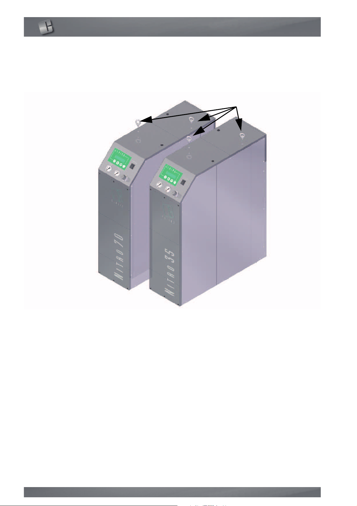
The generator removal from the pallet can be performed using the two eyebolts
included in the supply. These must be mounted on the top of the generator instead of the two black plastic screws (following picture).
4.2.4.
4.2.5.
m
Positioning
The choice of the installation area of the generator must consider a minumum
access space for the user and for the maintenance: we reccomend to let a free
space of at least 50 cm both from the front panel and from the back panel.
Assembly stabilizers
GENERATOR UNSTABLE,to avoid damage caused by the overturning of
generator on people or things Claind has planned the assembly of the
stabilizers.
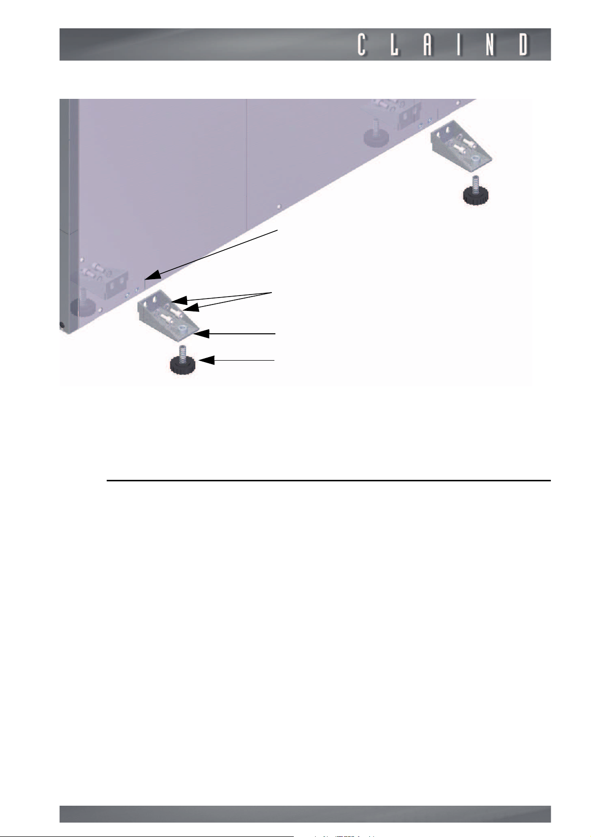
Assembly the feet (D) with the stabilizer brackets (C).
Using screws and washes (B) in dotation to block the stabilizer brackets (C) to
the generator (A).
10
Page 11
Nitrogen Generators Nitro35 Nitro70
A
B
C
D
e
4.3.
Use a allen key 4 mm to screw the feet and lift the generator from ground.
Claind disclaims any liability for damage to things, animals and people caused by
the overturning of generator caused by a lack of stabilizers.
Pneumatic connections
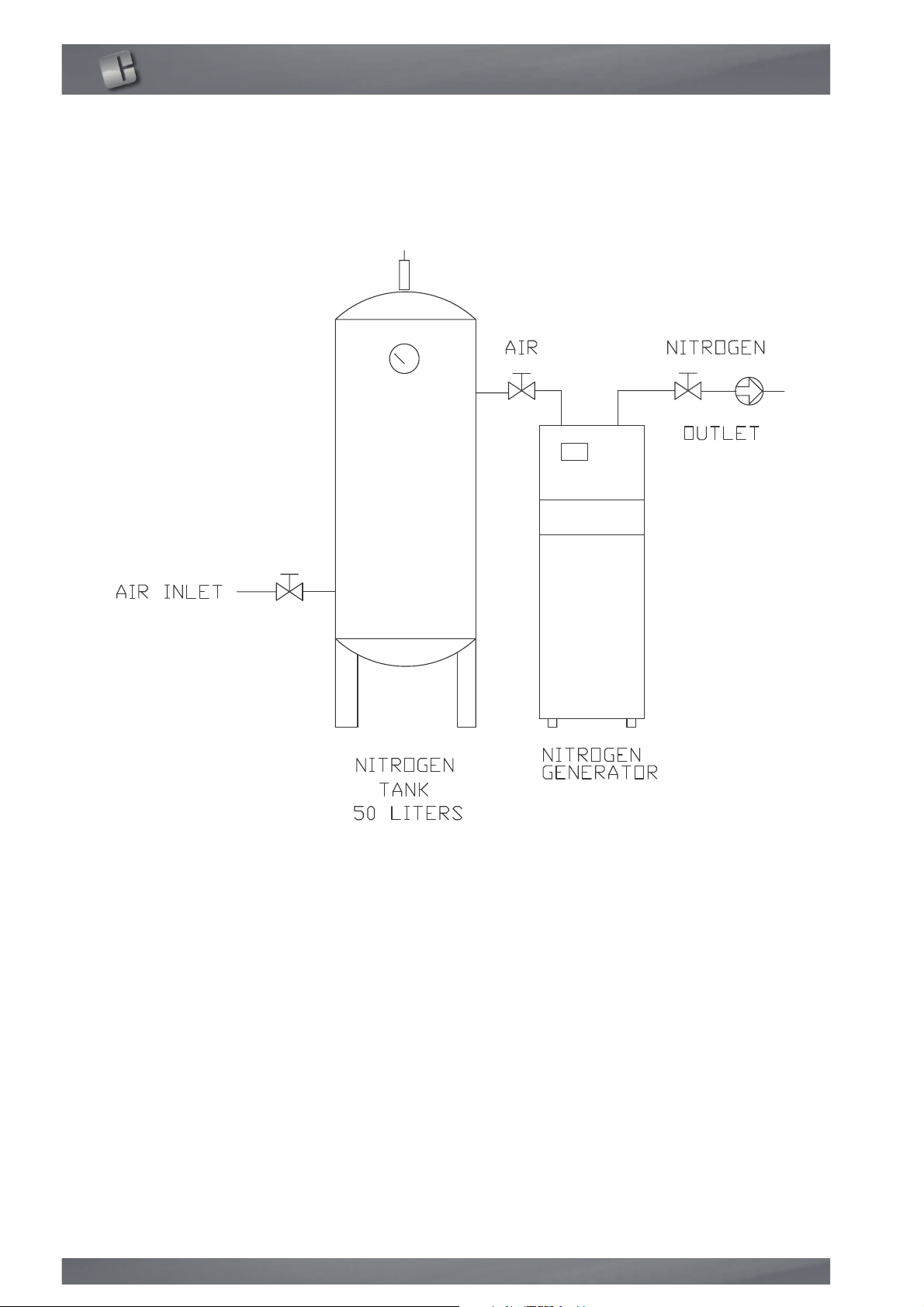
The picture shows the elements that constitute a tipycal Nitrogen generation
plant. The fittings for pneumatic connection of the various components of the
plant (Nitrogen generator, compressed air reservoir, user) are located on the
back of the generator. The external air reservoir must be used only when the
tubes that connect it to the machine exceed 50 m lenght. It is possible to have
a longer line using tubes with nominal diameter > 8mm.
11
Page 12
Installation
e
For an easy installation, we recommend to use flexible polyammide hose. The
generator is supplied along with automatic fittings for polyammide tube 8 x 10
mm. diameter.
.
4.3.1.
12
Nitrogen outlet
The generator produces Nitrogen at a set purity (between 97% and 99,99%) according to the needs of the user in phase of purchase order. The generator is
set in CLAIND facilities at the requested purity and can’t be reset by the user at
a different purity without the intervention of qualified CLAIND technician.
Nitrogen flow rate is depending from the model and from the requested purity.
Outlet pressure depends from the minimum intake compressed air pressure.
You can consider that the maximum pressure of Nitrogen is about 1,5 bar less
than the intake compressed air pressure.
Page 13
Nitrogen Generators Nitro35 Nitro70
1
e
During the first start-up, the Nitrogen reservoir will be full of air: the final purity
will be reached only when the total volume of air will be purged with the Nitrogen
fluxed by the generator. The requested time for this operation depends from the
model of the generator, from the requested purity of the Nitrogen as well as
from the volume of the reservoir itself.
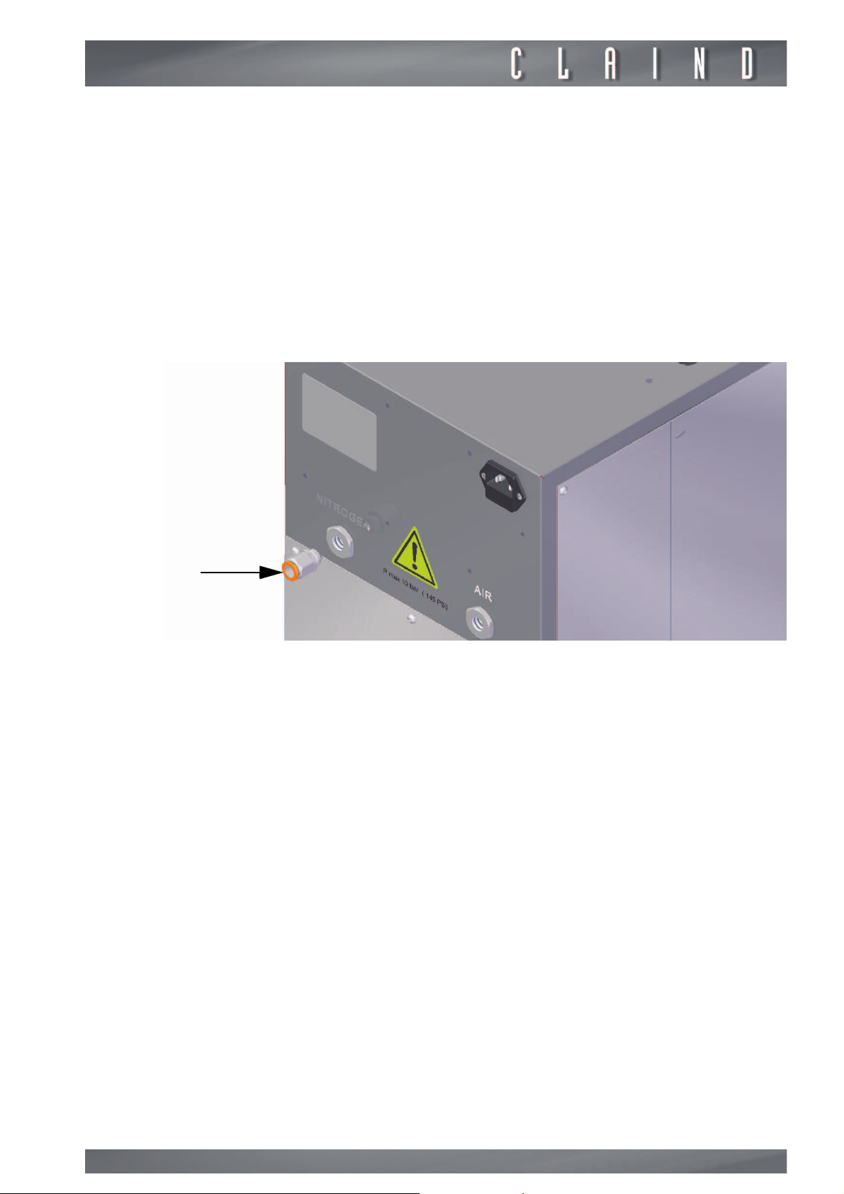
CONNECTION
• Locate Nitrogen connection, that is indicated by the script NITROGEN on the
back of the generator;
• take the fitting (1), and mount it;
• connect the line.
e
4.3.2.
e
e
We recommend to insert an on-off valve on the flow on the outlet line.
Air inlet
The specification the inlet compressed air are very important for the performance and for the working life of the Nitrogen generator.
In addition to the minimum requirement of pressure and flow rate (specific of
the model of the generator), compressed air must comply to following specification:
(ISO 8573-1; class 1-4-1):
Dew Point< 3° C
Max. oil content:< 0,01 mg/m
Max. particulate concentration (0,1 µm diameter)< 0.1 mg/m
In case of utilization of a poor quality air, permanent damages to the generator
can occur. In this case, Claind won’t be liable for the damages and the costs of
the possible reparation will be charged to the Customer.
Puirty of produced Nitrogen decreases as the pressure of the compressd air decreases. It is highly recommended to install a reservoir in case that the line isn’t
adequately dimensioned. In case of any need of clarification, please do not hesitate to contact CLAIND for other suggestion on the kind of compressed air
plant (compressor, dryer, filters and reservoir) adequate for the specific application.
3
3
13
Page 14
Installation
1
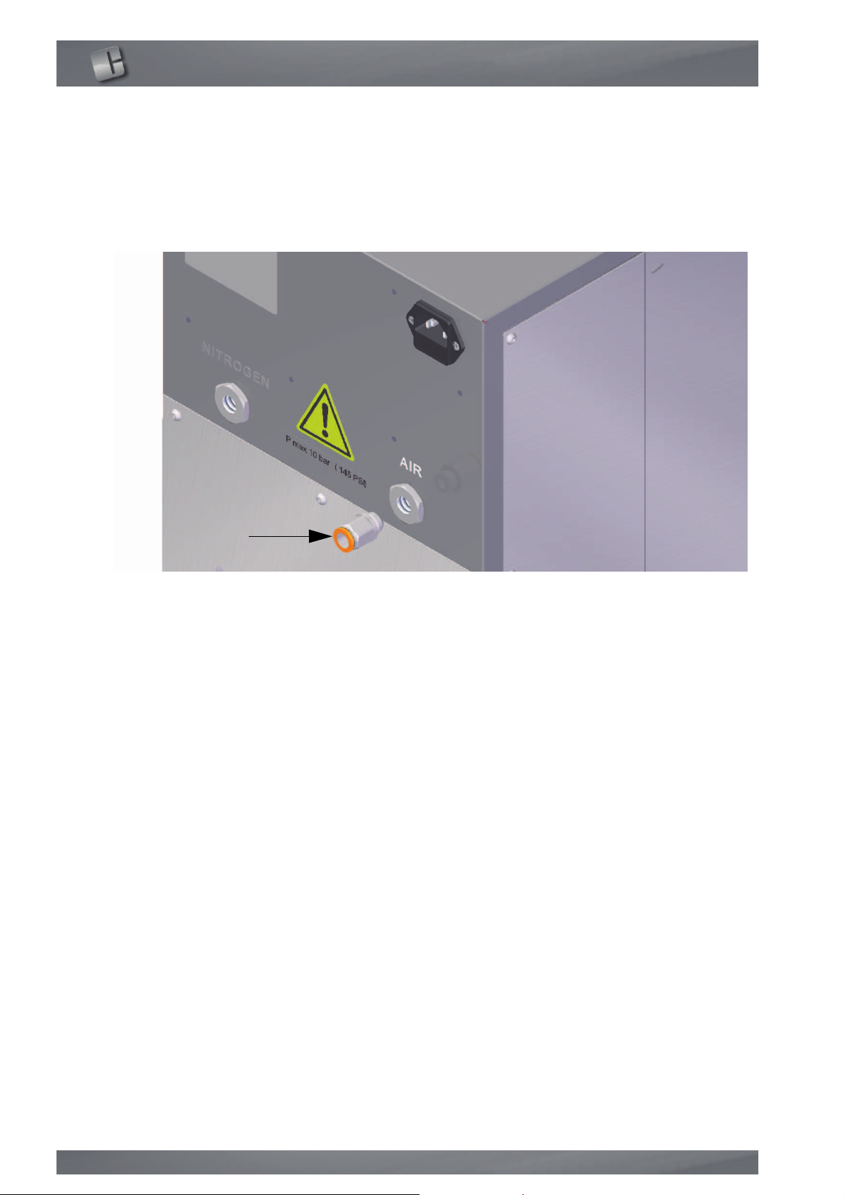
CONNECTION
• locate on the rear of the generator the connection of air marked as “AIR”;
• take the fitting (1), and mount it;
• connect the pipe;
• connect the other end of the pipe to the compressed air reservoir (up fitting).
e
we recommend to insert an on-off valve on the outlet line flow.
14
Page 15
Nitrogen Generators Nitro35 Nitro70
1
4.3.3.
c
c
Power supply
It is mandatory to apply literally following instructions for your own
safety.
Electric installation must comply to the law, particularly for what concerning the
protection line.
Warnings for a correct installation:
• Do not use extension cables, adaptors or multiple plugs; when necessary, please
substitute the Schuko plug with another adequate plug.
• Do always connect the protection conductor.
• The power supply plug must be positioned in a easily accessible area.
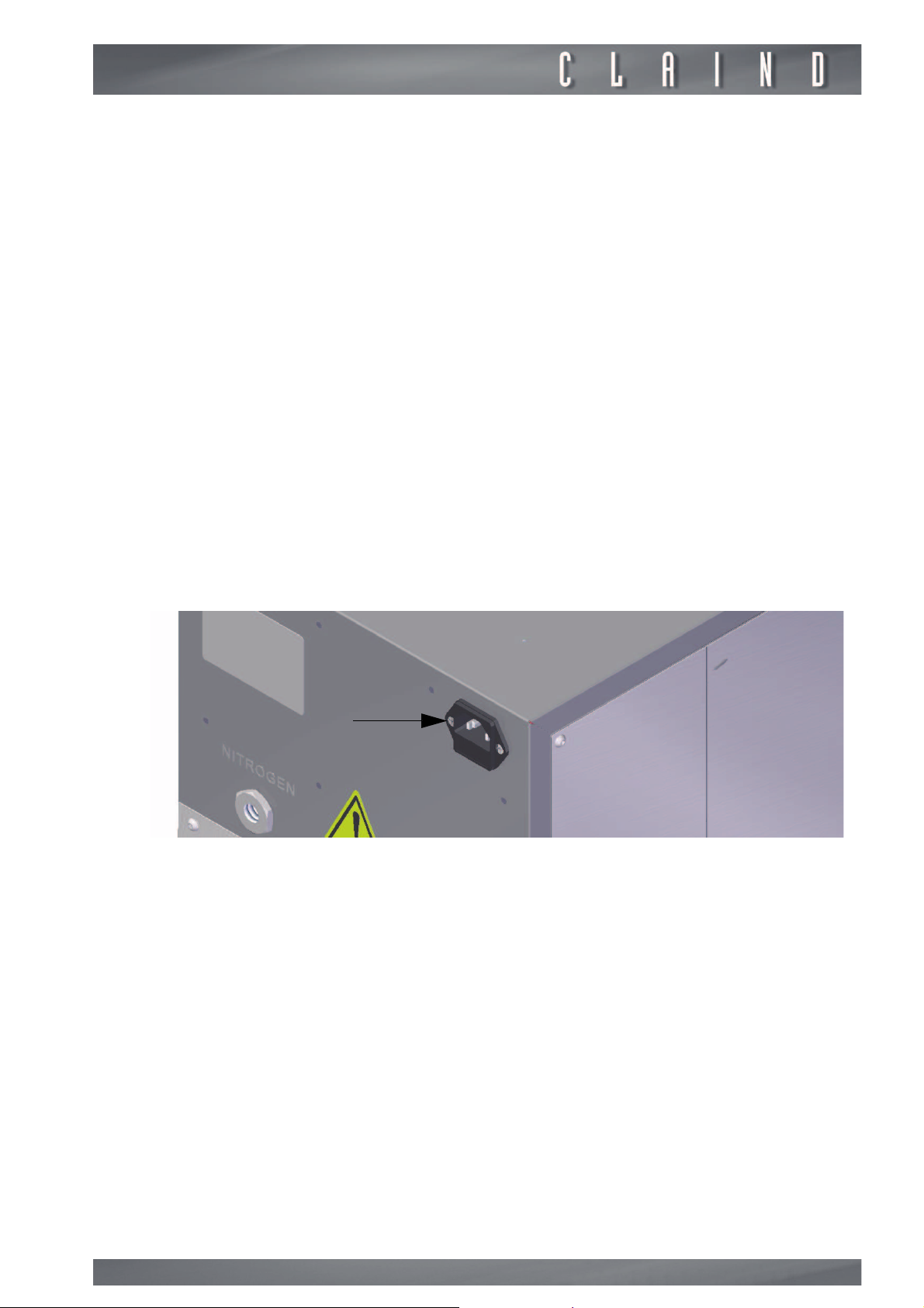
CONNECTION
• Please find the connection (1) for the power supply cable the on the rear of the
generator.
• Before of connecting the cable, please be sure that the POWER switch is in OFF
position.
• Please connect the power supply cable (2 m lenght, plug IEC320 C13 Schuko)
supplied with the generator.
15
Page 16

Installation
4.4.
e
e
e
4.5.
Warning
In case of non admissibility of a lack of gas supply (due to different causes such
as interruption of power supply, intervention of power supply protection, failure
of the generator), even though momentaneus, it would be opportune to forecast
a pneumatic distribution panel that allows the momentaneus and more or less
automatic insert of a spare gas sources.
As a precaution, the restart of a generator after the restoration of power supply
isn’t automatic, but manual on command of the operator.
When the automatic start of the generator after a black-out is necessary, it is
necessary to set this command in the set-up program
Packing disposal
It is recommended of keeping the original packing for possible future movimentation, since it guarantees an adequate protection to the generator.
16
Page 17

Nitrogen Generators Nitro35 Nitro70
5.
Disassembly and transport
5.1.
m
5.2.
e
Disassembly
• Stop the generator (
• wait for depressurization (about a minute);
• switch off the generator (
• disconnect the electric power cable;
• close all valves (air inlet, tanks, nitrogen) and detach the pneumatic
connections;
• unscrew the feet using the allen key 4 mm until the generator is free to move;
• unscrew the screws that block the stabilizers to the generator, put this
component in a bag and attached it to the generator.
After removal the stabilizers pay attention to the handling of the generator, THE GENERATOR IS UNSTABLE.
par. 6.5.
par. 6.6.
);
);
Transport
Remember that during transport the generator must always remain in a vertical
position.
If conserved, use the original packaging; otherwise use a pallet of adequate dimensions to hold the generator, affixing instructions in visible locations, such as:
THIS WAY UP, KEEP IT IN VERTICAL POSITION.
Lift the generator with the eyebolts in dotation.
17
Page 18
6.
Use
Use
6.1.
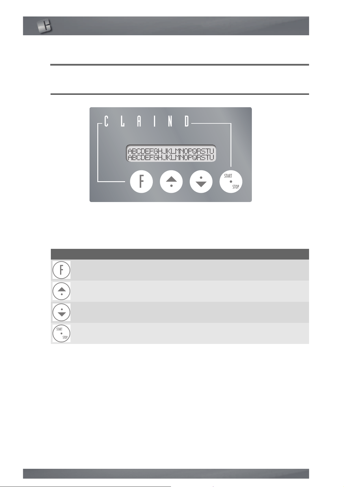
Keypad and display
KEYPAD
The user can interact with the generator, giving specific commands, display or
set parameters using the keypad on the front panel of the generator.
The chart below shows the use of the different keys on the keypad:
Key Fuction
Function It selects a function of the generator
Cursor It increases the selected value
Cursor It decreases the selected value
Operative It starts or stops the generator
DISPLAY
The display is composed by two lines of 20 characters each.
The upper line usually shows the functions and parameters, while the lower line
displays the related status and values.
Should the message exceed 20 characters, it is displayed sliding.
18
Page 19

Nitrogen Generators Nitro35 Nitro70
6.2.
6.2.1.
6.2.2.
First start-up
Configuration
The brand new generator is set and ready to start production. The user can access to the parameters set up menu (i.e. language, start-up mode, etc. ).
Please see par. “Parameters setting”.
Working sequence
1. Verify that all connection are made according to what described in chapter 4
(INSTALLATION).
2. Verify compressed air pressure.
3. Shut the Nitrogen line down, at the outlet of the generator.
4. Switch the generator on, switching on the POWER key (see par. 6.3 “Switching
on the generator).
5. Start Nitrogen production pushing the START-STOP key (see par. 6.4. Nitrogen
production).
6. Wait till the generator reaches the stand-by condition. In this condition, the
generator stops the normal production cycle and the display shows the
message STAND-BY.
7. From this moment on, Nitrogen is available in the line, opening the valve
shutted in point 2.
8. Flux in the enviroment for at least 30 minutes in order to clean the pipeline and
the reservoir.
6.3.
Switching on the generator
To switch on the generator, please turn the POWER switch on the front panel
“ON”.
The display lights up and the depressurization cycle starts automatically after
few seconds. In this phase, that last max. 30 seconds, the following message is
displayed:
PLEASE WAIT
DEPRESSURIZATION IN PROGRESS
Once depressurization is completed, the following message appears:
GENERATOR READY
In this status, the generator is ready to accept the production command (see
par. 6.4.) or the switch off command (see par. 6.6.).
19
Page 20

Use
6.4.
6.5.
Nitrogen production
When the generator ends the preparation phase (par. 6.3.) and the message
GENERATOR READY
tion in the following way.
Push the operative button START/STOP.
The productive cycle is started and the following message appears:
appears on the display, you can start Nitrogen produc-
PRODUCTION
Stop the generator
The generator can be stopped any time during production, just by pressing the
START/STOP key.
The following message appears during depressurization, that usually lasts 30-60
seconds:
PLEASE WAIT
DEPRESSURIZATION IN PROGRESS
e
6.6.
6.6.1.
PLEASE NOTE: the START/STOP key is not operative during a block of production..
The following message appears at the end of pressurization:
GENERATOR READY
At this time, you have two alternatives:
1. to switch off the generator turning OFF the POWER switch (see par. 6.6.)
2. to start again production pushing the START/STOP key (see par. 6.4.)
Switching off the generator
Correct switch off
The correct switch off of the the generator must be started from the
TOR READY
Turn the “POWER” switch OFF to switch off the generator .
status. The par. 6.5. describes how to reach this condition.
GENERA-
6.6.2.
20
Incorrect switch off
Please avoid of switching off the generator directly without doing the stop operation described in par. 6.5.
Page 21

Nitrogen Generators Nitro35 Nitro70
When this happens incidentally or for lack of power supply, the generator will
dispaly the following message:
WARNIING.
UNCORRECT SWITCH -OFF
To switch-off the alarm, push the Function key .
6.7.
Parameters display
6.7.1.
Display of the mode of the generator
During production, the main page of the display will show the message:
PRODUCTION
In order to have more information on the mode od the generator, please press
up arrow key . The display will show the following menu:
ARIA N2 YYYY
W.WW X.XX ZZZZ
Where:
W.WW
X.XX
YYYY
ZZZZ
The values are updated continously in order to verify the correct operation of the
generator.
To quit this page and go back on main menu, press the down arrow key .
= Air pressure at the intake of the sieves, in bar
= pressure of Nitrogen in the reservoir, in bar
= working phase of the molecular sieve CMS1
= working phase of the molecular sieve CMS2
6.7.2.
Working hours display
The generator counts the working hours (meant as the time during which the
generator is in
In order to display the working hours, you have to come back on main page
(
PRODUCTION
To exit this page and come back on main page, press twice up arrow key .
PRODUCTION
) and then press twice the down arrow key .
mode), till a maximum value of 65535 hours.
21
Page 22
Use
6.8.
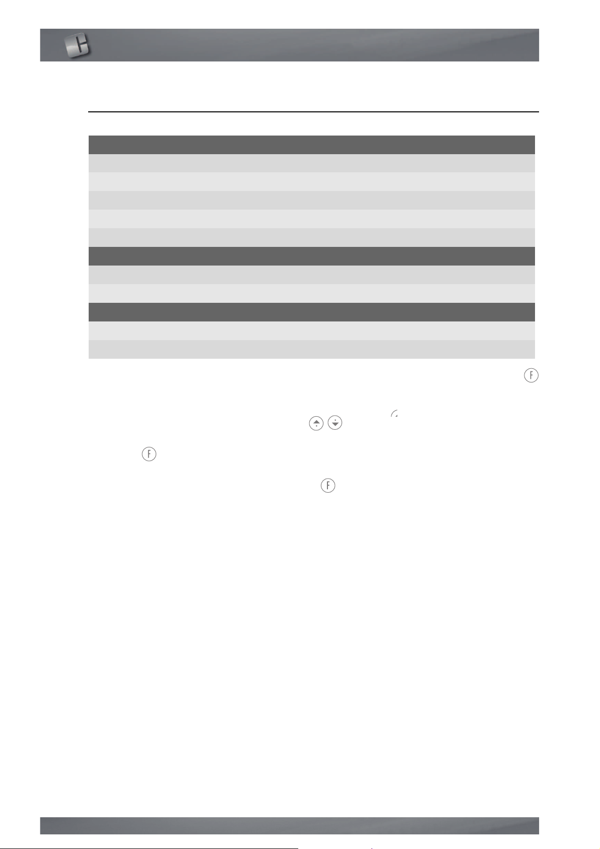
Setting of parameters
Message language
Italian
English
German
French
Spanish
Restoration of production after incorrect switch off
Manual
Automatic
Incorrect switch-off alarm
Enabled
Disabled
To access to this parameters turn on the generator pushing the Function key
for some seconds.
The date will be showed in sequence as indicated in the chart below.
To modify them, press the arrow keys .
To acquire the selected value, press the up arrow key, while pressing the Function key ,
Doing so you can also access to following parameter.
To exit this menu, press the Fuction key . for some seconds.
6.8.1.
Editing of maintenance parameters
See “Maintenance” par.
22
Page 23
Nitrogen Generators Nitro35 Nitro70
6.8.2.
e
6.8.3.
Setting of “Minimum nitrogen pressure” alarm
MINIMUM OUTLET PRESSURE
xx.x bar
This value represents the nitrogen pressure in the internal reservoir of the generator under which the
activated.
To access from main menu, press the Function key . This value can be increased or decreased pressing the Function key and selecting the arrow key
up or down .
To go back on main page, press the Function key . for some seconds.
The default value is 6.0 bar.
INSUFFICIENT NITROGEN PRESSURE.
Outlet nitrogen pressure regulation
• The regulator is positioned on the front of the generator (see par. 3.3.1).
• Please rotate the knob to regulate the pressure to the desired value (clockwise
to increase the pressure) displaying it on the gauge installed on the left.
alarm is
e
The default value is 0.0 bar (outlet closed).
23
Page 24
Maintenance
7.
Maintenance
The generator is equipped with a list of consumable components for each of
them a working time is preset during the testing phase, in order to enable the
user to perform programmed maintenance.
This time is decreased till its expiry during normal operation. When the time is
over the generator generates automatically a request for maintenance intervention.
m
7.1.
Before to do any type of operation on the generator, make sure that
are mounted the stabilizers
(par. 4.2.5.)
.
Deadline warnings
When the forecasted autonomy of a component expires during normal operation, an alarm message is displayed, for example:
WARNING
EXHAUSTED SILENCER
In order to acquire the message, press the Function key .. The message disappear following this operation, and you can procede with normal operation.
The generator will ask if the maintenance has been performed every successive
switching on, showing on the display a message, for example:
SILENCER SUBSTITUTION DONE?
24
NO
Pressing the up arrow key ” select the reply “YES” oR “NO” consequentely.
To acquire the reply after selecting it press the function key.
Should the reply be “NO”, the message will be repeated to next switch off;
Should the reply be “YES”, the generator sets a new working time of the component (the same set the first time) for a future maintenance.
Should be the alarm for incorrect switch-off be present, this procedure isn’t activated; it will be anyhow available for next start up.
Page 25
Nitrogen Generators Nitro35 Nitro70
7.2.
Maintenance kit
The following kit for the maintenance of the generator are available. They have
to be substituted after the following time intervals:
Maintenance kit Part number Frequency of substitution
0-8000 h 0-16000 h
7.3.
e
e
e
Maintenance kit
8000 h
Maintenance kit
16000 h
423.93.0005 1 1
423.93.0014 1
Maintenance schedule
We recommend to follow the suggested maintenance schedule in order to keep
the generator efficient and to reduce failure risks.
The following chart indicates the frequency of the recommended maintenance
operation, express in “working hours” of the generator.
Warranty is granted only on original parts
Maintenance has to be effected only by technician authorized by Claind.
If a correct maintenance schedule is not followed, the performance of the generator may no longer be ensured and it may lead to permanent damage to the
generator.
Part number Description 4000 h 8000 h 12000 h 16000 h
R061040 CMS silencer 1/2” 2 2
Maintenance kit to be used -> 423.93.0005 423.93.0014
25
Page 26

8.
Troubleshooting
Troubleshooting
8.1.
8.2.
Unsufficient Nitrogen pressure alarm
This alert is activated once that, because of an exceeding Nitrogen consumption
or of an insufficient inlet compressed air pressure, the pressure in the built-in
reservoir drops below the MINIMUM NITROGEN PRESSURE that has been set
To shut down the alarm, press the Function key .
To exit from the alarm mode, the pressure inside the reservoir has to rise over
the minimum value (for example by reduding the Nitrogen flow rate or increasing compressed air pressure).
High compressed air alarm
When the inlet compressed air pressure exceeds 10 bar, the corresponding
alarm appears. In order to exit from alarm mode, switch off and turn on again
the generator.
26
Page 27

Nitrogen Generators Nitro35 Nitro70
9.
Guarantee
The conditions of guarantee are as follows: 12 MONTHS as of the date of
installation, but NO MORE THAN 14 MONTHS as of the date of delivery.
The guarantee includes the cost of materials and labour.
The guarantee is EX WORKS CLAIND and therefore does not include any callout
costs for technicians to visit the client’s premises.
The guarantee covers exclusively COSTS DERIVING FROM MANUFACTURING
DEFECTS and does not include:
1. Damage caused by negligence or improper use of the equipment.
2. Damage caused by inadequate electric power supply.
3. Damage caused by natural catastrophes (e.g. fire).
4. Damage caused by transport.
5. Damage caused by compressed air with inadequate properties.
The guarantee is rendered null and void in the event of intervention by unauthorised personnel on the equipment.
27
Page 28
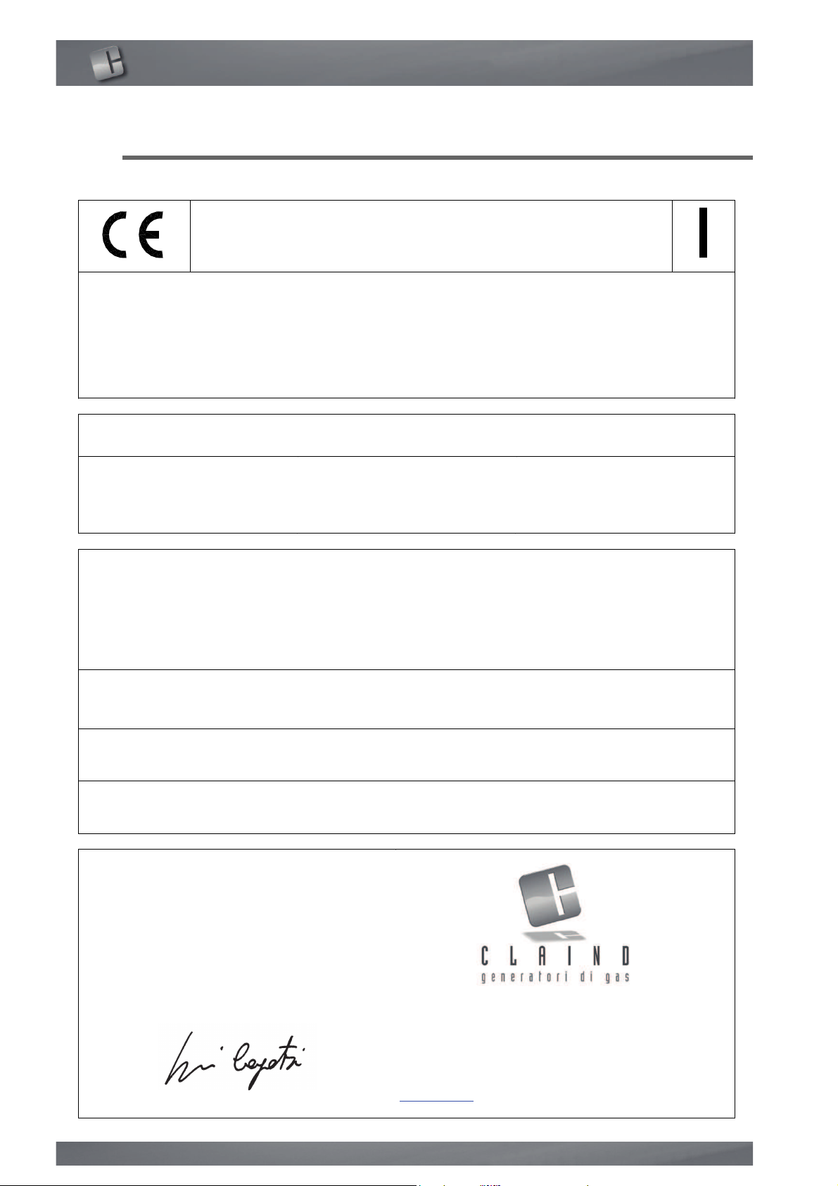
Declaration of conformity
MO10MCC Emiss. 26/10/2012
',&+,$5$=,21(',&21)250,7$
(DECLARATION OF CONFORMITY)
Con la presente dichiariamo, sotto la nostra esclusiva responsabilità,
FKHO¶DSSDUHFFKLDWXUDWLSR
(By this letter we declare, under our responsibility, that the following apparatus:)
CODICE
(Part number)
VERSIONE
(Version)
DESCRIZIONE
(Descritpion)
423.01.0130
2
Nitro70
423.01.0230
2
Nitro35
alla quale questa dichiarazione si riferisce, è conforme con quanto
stabilito dalle seguenti disposizioni, in particolare:
(to which this declaration regards, is fully in conformity with the following rules:)
2014/30
UE
Direttiva compatibilità elettromagnetica (EMC)
(Electromagnetic compatibility directive)
2014/35
UE
Direttiva bassa tensione (LV)
(Low voltage directive)
2014/68
UE
Attrezzatura in pressione (PED)
(Pressure equipment)
Tremezzina, 19/07/2016
Firma del legale rappresentante
(Signature of legal representative)
Giovanni Cogotzi
Via Regina 24, 22016 Tremezzina
Loc. Lenno (CO) Italy
Tel. ++39-0344-56603
Fax. ++39-0344-56627
e-mail: [email protected]
www.claind.it
10.
Declaration of conformity
28
Page 29

Nitrogen Generators Nitro35 Nitro70
11.
Notes
29
Page 30

Claind srl
Via Regina, 24
22016 Tremezzina Loc. Lenno (CO) - Italy
Tel +39 0344 56603
Fax +39 0344 56627
e-mail [email protected]
Nitro35 - Nitro70 eng Rev6.fm
 Loading...