

Page 1

User’s Manual
Nitrogen
Generator
NiGen HF NiGen LCMS
Page 2
2
Table of contents
1. Introduction 3
2. Safety 4
3. Description of the generator 6
4. Installation area requirements 12
5. Installation 14
6. Disassembly and transport 19
7. Use 20
8. Maintenance 28
9. Troubleshooting 33
10. Guarantee 37
11. Declaration of conformity 38
12. Notes 39
Page 3

Nitrogen Generator NiGen HF - NiGen LCMS
3
1.
Introduction
This document is intended for users of nitrogen generator models NiGen HF and
NiGen LCMS, and provides all information regarding installation, use and maintenance.
The generator is intended to be used as a source of nitrogen gas for laboratory
applications, including gas chromatography, ICP, LCMS, sample preparation,
etc..
The manual covers the following models:
As regards installation and maintenance, it is assumed that the user is familiar
with pneumatic circuit components, and in particular is aware of the safety aspects of compressed air and nitrogen.
The margin of the text contains the following symbols, indicating:
m
compulsory safety standards to be observed
c
electrical hazard
e
recommendations and important information
It is strongly recommended to carefully read all safety warnings (
par. 2.1.
) be-
fore carrying out any operation on the generator.
Serial number Model
422.02.0310 NiGen HF-0
422.02.0440 NiGen HF-1 115 Vac 60Hz
422.02.0450 NiGen HF-1 230 Vac 50Hz
422.02.0460 NiGen HF-1 230 Vac 60Hz
422.02.0710 NiGen LCMS 40-0
422.02.0640 NiGen LCMS 40-1 115 Vac 60Hz
422.02.0650 NiGen LCMS 40-1 230 Vac 50Hz
422.02.0660 NiGen LCMS 40-1 230 Vac 60Hz
422.02.0810 NiGen LCMS 100-0
Page 4

Safety
4
2.
Safety
e
The unit must be installed and used in observance of the instructions in this booklet. Furthermore, use of the generator must be limited to that described in
Chapter 1 Introduction
. Failure to observe the foregoing will render the guarantee null and void and release CLAIND from all liability for direct or indirect damage or physical injury.
e
The user is responsible for asking local authorities if there are local safety regulations that are stricter than what is described in this manual.
2.1.
Warnings
m
Place the generators FAR FROM SOURCES OF HEAT
m
Place the generators in an environment PROTECTED AGAINST RAIN
AND WIND
c
NEVER OPEN the generator while it is connected to the electrical
mains: RISK OF FATAL INJURY BY ELECTROCUTION
e
Repairs and inspections must be carried out exclusively by QUALIFIED PERSONNEL: in the event of faults which cannot be resolved according to the pro-
cedures listed in the TROUBLESHOOTING chapter, contact exclusively our
authorized Technical Assistance.
e
If the generator is not to be used for a prolonged period of time, it must be depressurised (par. 7.6. and par. 7.7.).
2.2.
Notes on the use of nitrogen
Nitrogen is not a toxic gas, but when the percentage in the air exceeds specific
values there is a risk of asphyxia.
Therefore NEVER DIRECTLY INHALE the gas produced and avoid working in the
vicinity of a flow of nitrogen.
However, given the low quantities produced, it is sufficient that the flow of nitrogen occurs in a normally ventilated environment to avoid the risk of accumulation
(par 4.2.1.).
Page 5
Nitrogen Generator NiGen HF - NiGen LCMS
5
2.3.
Safety devices
MAXIMUM PRESSURE: the control system constantly monitors the pressure.
In case of anomalous pressure, a safety valve (which operates independently of
the control system) prevents it exceeding 10.5 bar (152 psi).
2.4.
Technical assistance
The CLAIND technical assistance can be contacted as follows:
Phone ++39 0344 56603
Fax ++39 0344 56627
Email: [email protected]
Website: filling the form on the website www.claind.it at the “Service” section
Page 6

Description of the generator
6
3.
Description of the generator
3.1.
Equipment supplied
Unless otherwise agreed, the forniture includes:
• n°1 nitrogen generator;
• n°1 CD user’s manual;
• n°1 applicable declarations of conformity of tank and safety valve;
• n°1 cable for the electrical mains;
• n°1 fitting for plastic tube external diameter 4mm;
• n°1 fitting for plastic tube external diameter 6mm;
• n°1 fitting for plastic tube external diameter 10mm;
• 2 mt of plastic tube external diameter 4mm;
only for generator NiGen HF the forniture includes:
• n°1 brass fitting for copper tube external diameter1/4”.
3.2.
Technical specifications
3.2.1.
Nitrogen
(*) the flow rate is given at 20°C and 1 atm
(**) purity referred to residual oxygen
3.2.2.
Compressed air supply table
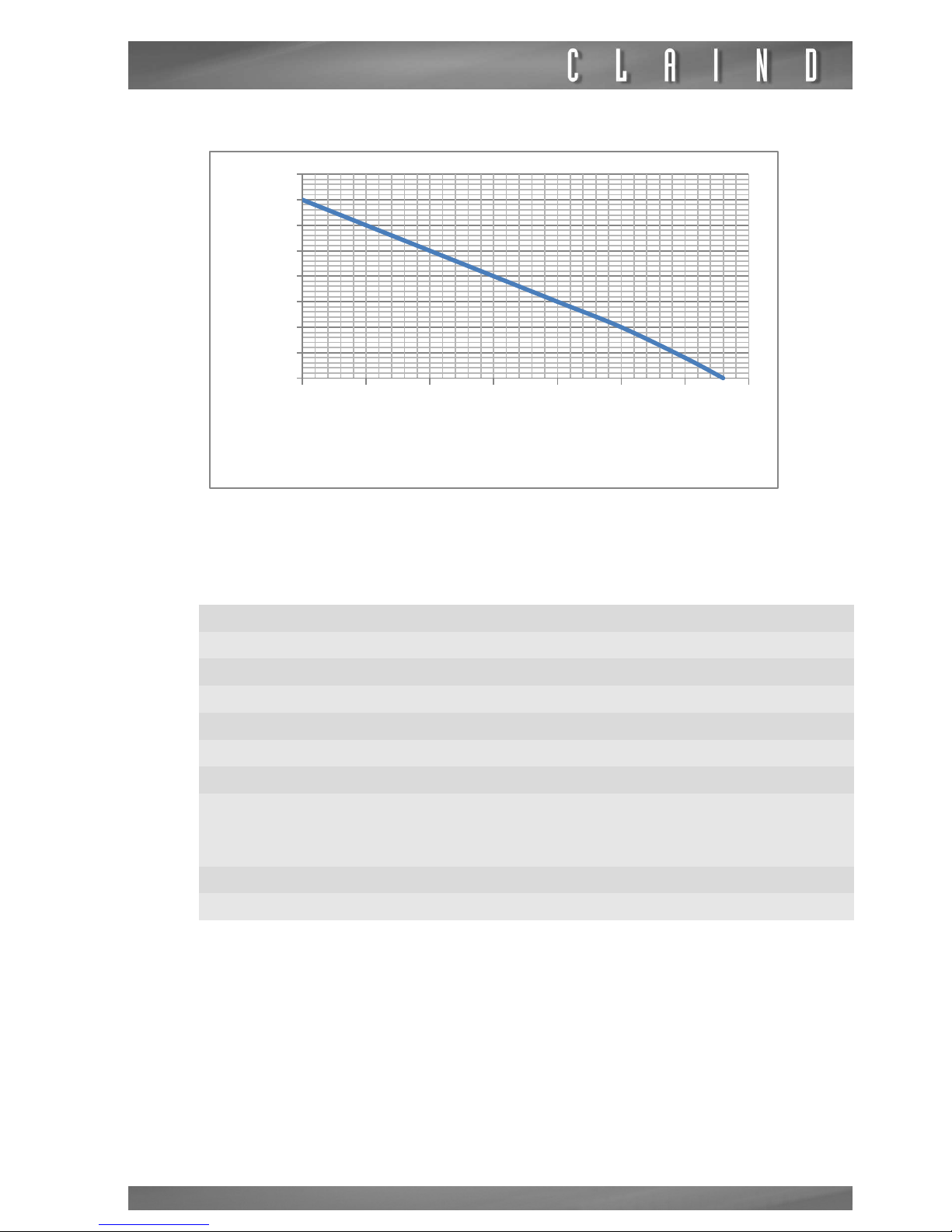
NiGen LCMS 40-1 and HF-1 produce nitrogen and compressed air.
This table shows on X axes the nitrogen product, and on Y axes the compressed
air available only for the model LCMS 40-1.
Max flow rate (*)
NiGen HF-0 6 Nl/min 6 slpm
NiGen HF-1 6 Nl/min 6 slpm
NiGen LCMS 40-0 40 Nl/min 40 slpm
NiGen LCMS 40-1 40 Nl/min 40 slpm
NiGen LCMS 100 100 Nl/min 100 slpm
Pressure
settable from 0 to
7 bar
settable from 0 to
100 psi
Purity (**)
NiGen HF up to 99.9995 %
NiGen LCMS up to 99.9 %
Page 7
Nitrogen Generator NiGen HF - NiGen LCMS
7
For the HF-1 the maximum flow of outlet compressed air is 14 Nl/min.
3.2.3.
Compressed air supply, specifications
not applicable to
NiGen HF-1 and NiGen LCMS 40-1
(***) for further details on the air quality, see the specifications for Class 1-4-1,
ISO 8573-1
Pressure
minimum 8.5 bar 120 psi
maximum 10 bar 145 psi
Flow rate
NiGen HF-0 36 Nl/min 36 slpm
NiGen LCMS 40-0 100 Nl/min 100 slpm
NiGen LCMS 100 250 Nl/min 250 slpm
Particulates: maximum concentra-
tion of particles of diameter less
than 0.1 µm (***)
less than 0.1 mg/m³
Oil concentration less than 0.01 mg/m³
Humidity dewpoint under pressure less than 3°C
\
0
5
10
15
20
25
30
35
40
5 10 15 20 25 30 35 40
Air [Nl/min]
N2 [Nl/min]
Page 8
Description of the generator
8
3.2.4.
Electrical requirements
3.2.5.
Pneumatic connections
3.2.6.
Electrical connections
NiGen HF-0,
NiGen LCMS 40-0,
NiGen LCMS 100
115-230 Vac (±10%), 1 ph, 50/60Hz;
50 W
NiGen HF-1,
NiGen LCMS 40-1
depending on model:
115 Vac (±10%); 1ph; 60Hz; 1.9 kVA
or
230 Vac (±10%); 1 ph; 50Hz; 1.6 kVA
or
230 Vac (±10%); 1 ph; 60Hz; 1.9 kVA
Nitrogen outlet G 1/4" female
Air outlet
not applicable to
NiGen HF-0, NiGen
LCMS 40-0 and NiGen LCMS 100
G 1/4" female
Drain
not applicable to
NiGen HF-0, NiGen
LCMS 40-0 and NiGen LCMS 100
G 1/8" female
Compressed air supply
not applicable to
NiGen HF-1 and NiGen
LCMS 40-1
G 1/4" female
Power supply socket IEC320-20
Page 9

Nitrogen Generator NiGen HF - NiGen LCMS
9
3.2.7.
Dimensions
3.3.
Generator components
3.3.1.
Front view
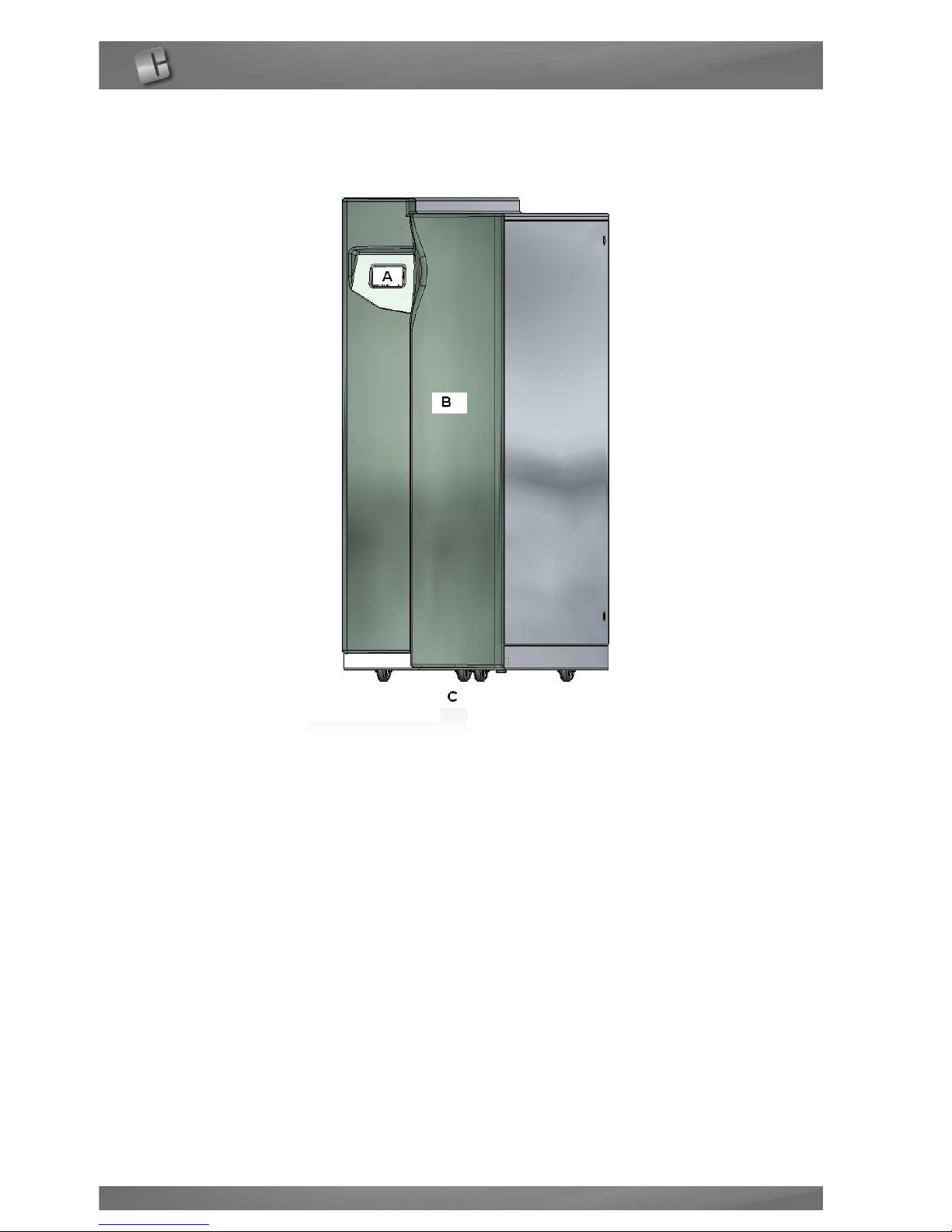
A. CPU: generator control unit; it is the user interface by way of the touch screen;
B. FRONT PANEL, removable for maintenance operations
C. FULL TURN WHEELS
Width 44 cm 17.3”
Depth 110 cm 43.3”
Height 130 cm 51.1”
Weight
NiGen HF-0 and NiGen LCMS 40-0
190 kg 420 lbs
Weight
NiGen HF-1, NiGen LCMS 40-1
220 kg 485 lbs
Weight
NiGen LCMS 100
200 kg 440 lbs
Page 10
Description of the generator
10
FIGURE 3.3.1: Front view
Page 11
Nitrogen Generator NiGen HF - NiGen LCMS
11
3.3.2.
Rear view
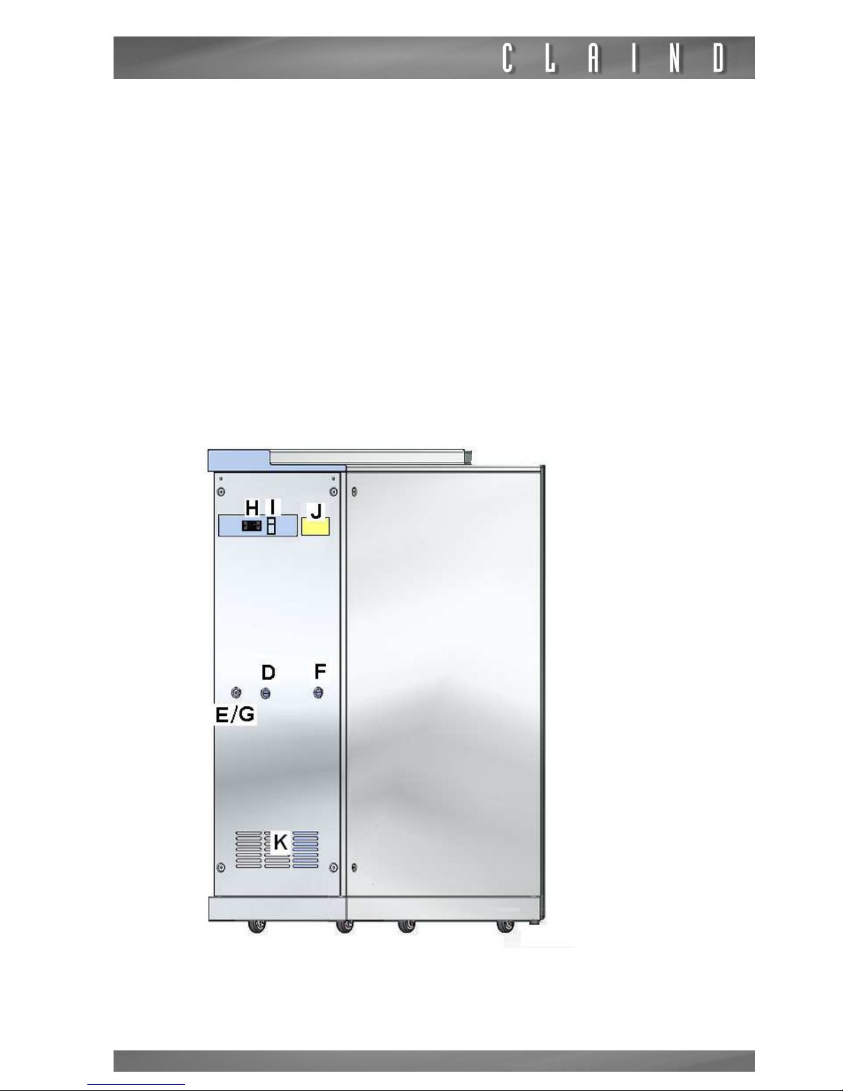
D. NITROGEN OUTLET: pneumatic connection for the generator’s nitrogen
delivery
E. AIR INLET: pneumatic connection for compressed air line inlet.
Not used for
NiGen HF-1 and NiGen LCMS 40-1
F. DRAIN: pneumatic connection for the condensation drain line.
Not used for
NiGen HF-0, NiGen LCMS 40-0 and NiGen LCMS 100
G. AIR OUTLET: pneumatic connection for an optional line for compressed air
produced by the compressor.
Not used for NiGen HF-0, NiGen LCMS 40-0 and
NiGen LCMS 100
H. CONNECTOR for electric power supply cable
I. “POWER" KEY: ON-OFF SWITCH
J. IDENTIFICATION LABEL: states the model, serial number (SN) and electrical
specifications
K. VENTILATION GRILLE
FIGURE 3.3.2. Rear view
Page 12

Installation area requirements
12
4.
Installation area requirements
4.1.
Environmental requirements
m
Place the generators FAR FROM SOURCES OF HEAT, PROTECTED
AGAINST RAIN AND WIND, and SHOULD NOT BE EXPOSED TO THE
SUN.
e
Failure to observe the precautions preclude the guarantee.
4.2.
Environmental ventilation
The environment where the generator is installed must be good ventilated to
prevent the risk of asphyxia and decreased the performance of the generator.
4.2.1.
Oxygen content in the ambient
m
If the generator and the point-of-use are located in different rooms,
the following minimum ventilation air flow must be provided to maintain acceptable oxygen content in the ambient. Don’t seal the rooms.
4.2.2.
Temperature
e
This paragraph is able only for these models: NiGen LCMS 40-1 and NiGen HF-1
m
Claind raccomanded to not go over the maximum environment temperature of 30°C for guarantee correct operations of the generator. If
this value is exceeded, in relation to the use of the generator, could appare the warning of maximum temperature of the compressor (E03)
(par.9.4.).
Are requires two openings of at least 0,5m2 to create a flow of air suffucient to
ensure air exchange.
It is also recommended to avoid danger of asphyxia.
Installation site enclosed, indoors
Relative humidity up to 80%, no condensation
Use temperature from 5°C to 35°C from 40°F to 95°F
Protection rating IP20
Page 13
Nitrogen Generator NiGen HF - NiGen LCMS
13
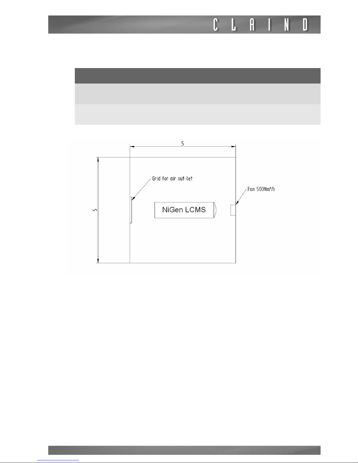
If the generator is located in a closed room, to prevent the risk of excessive temperature increase of air, we recomend the following minimum ventilations:
The maximum difference between the environmental temperature and the room
temperature with the generator must be 5°C.
if in the room there aren’t windows ensure that there is an pening for the outlet
of the air of larger cross-section of the fan.
Model Minimum ventilation of the room
NiGen LCMS 40-1
500 Nm3/h
18500 SCFH
NiGen HF-1
500 Nm3/h
18500 SCFH
Page 14
Installation
14
5.
Installation
5.1.
Generator positioning
5.1.1.
Handling
e
The generator must always remain in a vertical position as it is not designed to
be laid on its side.
Once unpacked, the generator can be moved on its wheels.
5.1.2.
Packaging removal
m
Two people are required for this operation
The generator is delivered packed in a crate. Use the rear wall of the crate as an
unloading ramp
e
If possible, store the packaging to ensure adequate protection when moved in
the future.
5.1.3.
Positioning
When choosing the installation area for the generator, take into account minimum clearances required for use and maintenance: ideally a free space should
be left of at least 50 cm from the front and rear panels. The clearance at the rear
of the generator, as well as for maintenance, is required to ensure efficient cooling of the compressor.
e
The generator is also equipped with four adjustable stationary feet
Page 15
Nitrogen Generator NiGen HF - NiGen LCMS
15
5.2.
Pneumatic connections
5.2.1.
Nitrogen outlet
m
The distribution line must be made of pipe rated for a pressure of at
least 10.5 bar (152 psi).
The pipe diameter must be sized on the basis of the acceptable pressure drop
values of the utility. Pipelines with an internal diameter of at least 8mm are recommended (e.g. polyamide pipe 10x8 mm).
e
To ensure nominal purity of the delivered nitrogen is maintained (minimize contamination from oil residue, dust, scaling and humidity), it is recommended to
use clean and/or treated pipelines for final gas distribution.
CONNECTION
• Locate the nitrogen coupling, marked “NITROGEN OUTLET” at the rear of the
generator.
• Connect the line.
5.2.2.
Air outlet
Not applicable to NiGen HF-0, NiGen LCMS 40-0 and NiGen LCMS 100
m
The distribution line must be made of pipe rated for a pressure of at
least 10.5 bar (152 psi).
CONNECTION
• Locate the compressed air coupling, marked “AIR OUTLET” at the rear of the
generator.
• Connect the line.
e
The outlet air pressure is adjustable from 0 to 8 bar
e
The available outlet air flow depends on the nitrogen consumption. Please refer
to the following tables
Page 16
Installation
16
LCMS 40-1
HF1
5.2.3.
Air inlet
not applicable to NiGen HF-1 and NiGen LCMS 40-1
CONNECTION
• Locate the compressed air coupling, marked “AIR INLET” at the rear of the generator.
• Connect the line.
m
The compressed air supply to the generator may not exceed 10.5 bar
(152 psi).
Nitrogen
outlet flow
[Nl/min]
Max available
air outlet flow
[Nl/min]
0 - stand-by 75
10 30
20 20
30 10
40 0
Nitrogen
outlet flow
[Nl/min]
Max available
air outlet flow
[Nl/min]
0 - stand-by 75
Production 14
Page 17
Nitrogen Generator NiGen HF - NiGen LCMS
17
5.3.
Drain
Not applicable to NiGen HF-0, NiGen LCMS 40-0 and NiGen LCMS 100
CONNECTION
• Locate the "DRAIN" outlet at the rear of the generator.
• Connect the condensation drain pipe (e.g., dia. 4 mm polyamide hose).
• Route the other end of the pipe into the condensate collection container.
m
The condensation is expelled by bursts of compressed air. If using a
flexible hose, make sure it is properly secured.
5.4.
Electric power supply
c
For reasons of safety, the following instructions must be strictly observed.
The electrical installation must comply with current standards, in particular regarding the protection line/ground wire.
c
Recommendations for correct installation:
• do not use extension leads, adaptors or multiple sockets;
• always connect the protection/ground wire;
• the mains socket and switch must be located in an easily accessible position.
• if the provided power cable does not match the local plug configuration, the
proper power cable with the appropriate configuration must be obtained prior to
attempting to apply power to the unit.
CONNECTION
• Locate power cable connector at the rear of the generator.
• Before connecting the cable, ensure that the POWER switch is set to OFF.
• Connect the power cable supplied with the generator.
Page 18
Installation
18
5.5.
Warnings
e
If a failure in gas supply (due to a power failure, activation of an electrical safety
device, or generator fault), even temporary, is not admissible, a pneumatic panel
should be envisaged, to enable provisional activation of a reserve gas source (totally or partially automatic).
5.6.
Packaging disposal
It is recommended to store the original packaging to ensure adequate protection
for the purifier when moved in the future.
Page 19
Nitrogen Generator NiGen HF - NiGen LCMS
19
6.
Disassembly and transport
6.1.
Disassembly
• Stop the generator
(par 7.6.);
• wait for depressurization (about a minute);
• switch off the generator
(par. 7.7.);
• disconnect the electric power cable;
•
only for NiGen HF-1 and NiGen LCMS 40-1
, depressurize the air tank, removing
the air outlet plug
(par. 3.3.2.)
and acting on the air outlet pressure regulator as
described at
par. 7.9.2.
Plug again the air outlet;
• carefully detach the pneumatic connections.
6.2.
Transport
e
Remember that during transport the generator must always remain in a vertical
position.
If conserved, use the original packaging; otherwise use a pallet of adequate dimensions to hold the generator, affixing instructions in visible locations, such as:
THIS WAY UP, KEEP IN VERTICAL POSITION.
Page 20
Use
20
7.
Use
7.1.
Operator interface
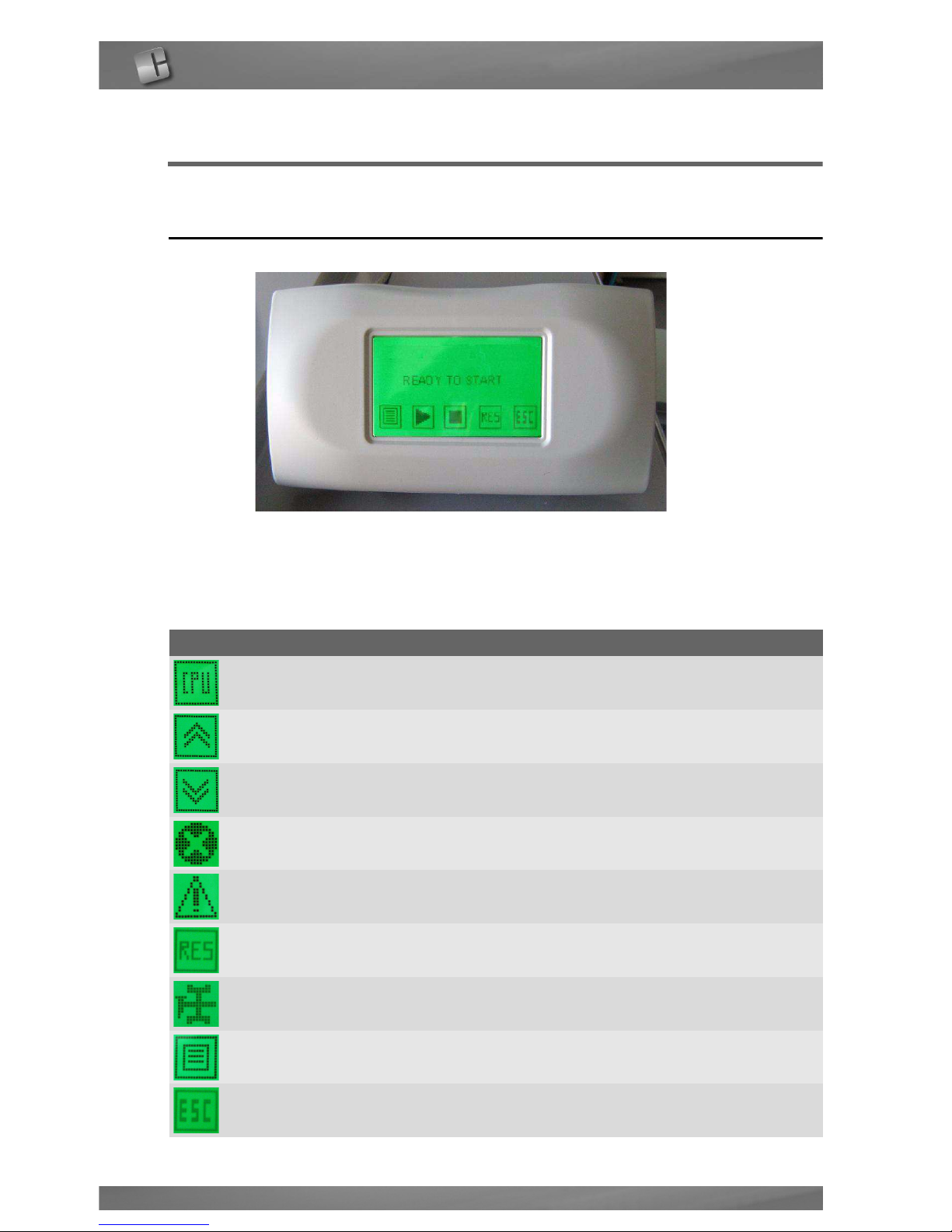
TOUCH SCREEN
The CPU screen enables the user to interact with the generator, i.e. give specific
commands or display and set parameters.
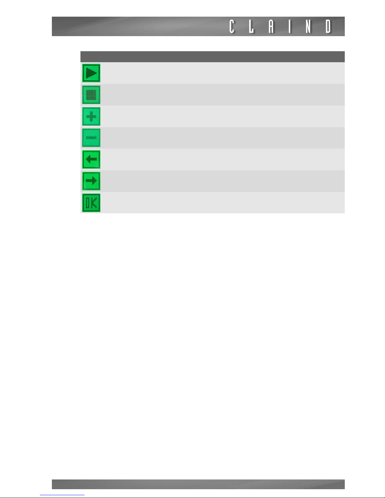
The table shows the function of the various keys on the screen:
Key Function
CPU access to CPU menu
PREVIOUS go to previous page
NEXT go to following page
ALARM access to list of alarms
WARNING access to list of warnings
RESET reset of alarms and warnings
MAINTENANCE go to maintenance request description
MENU access to different menus
ESC exit from menu
Page 21
Nitrogen Generator NiGen HF - NiGen LCMS
21
e
do not press on the touch screen with sharp objects
START start the production of gas
STOP stop the production of gas
INCREASE increase the value
DECREASE decrease the value
ADD add one digit
DELETE delete last digit
OK confirms modified value
Key Function
Page 22
Use
22
7.2.
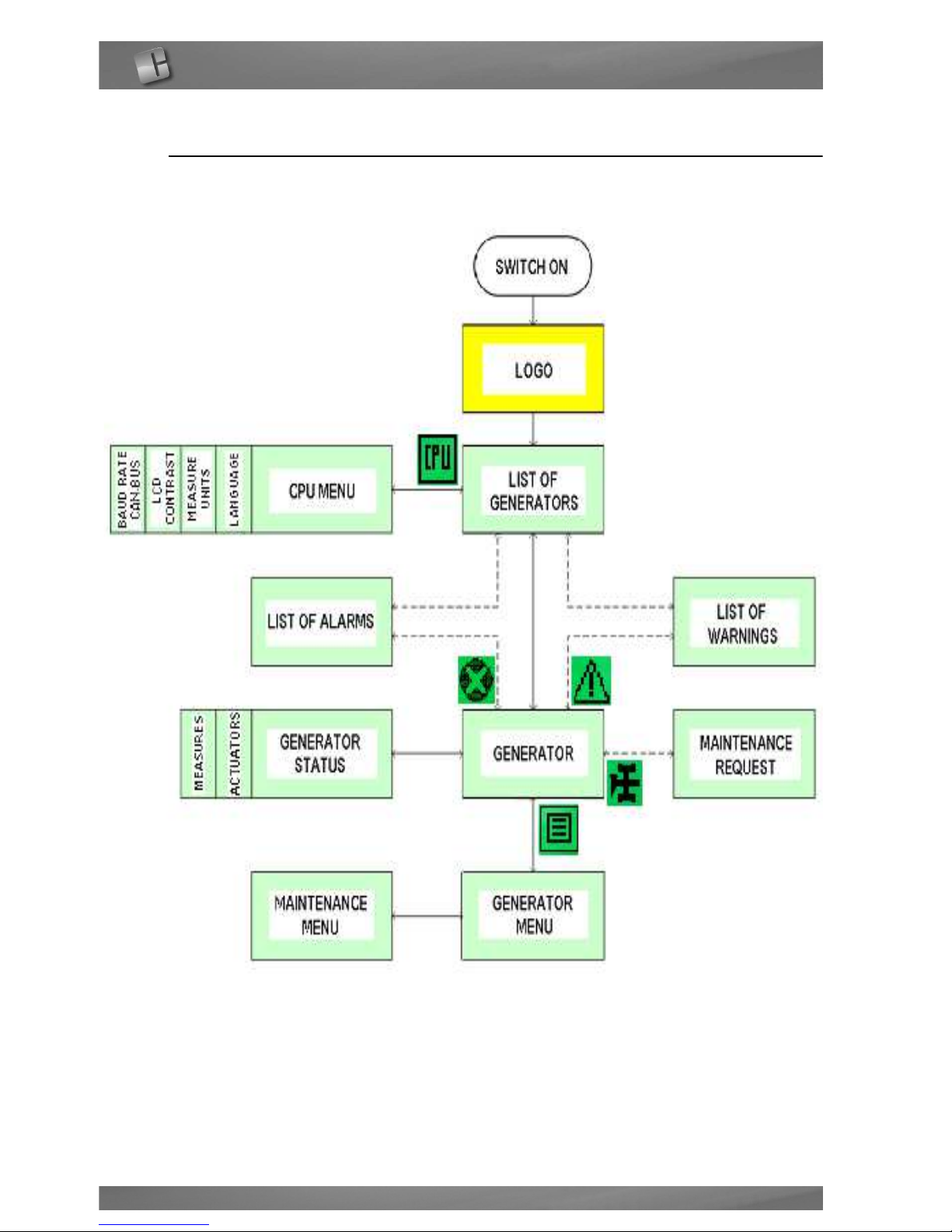
Menus
The following chart shows the accessible menus for the operator:
Page 23
Nitrogen Generator NiGen HF - NiGen LCMS
23
7.3.
Initial start-up
1. Check that all connections are made as specified in
par.4.;
2. close the nitrogen line downline of the generator;
3. switch on the generator, by setting the POWER switch to ON
(par. 7.4.);
4. start nitrogen production by pressing the START key
(par. 7.5.);
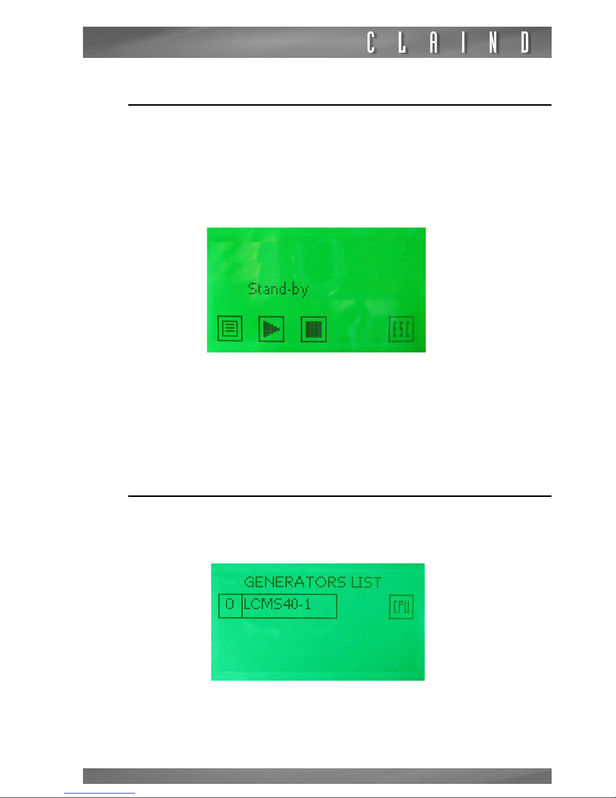
5. wait approximately 15 minutes, until the generator reaches the Stand-By
status. In this state, the generator suspends normal production, showing the
following page:
6. from this point the nitrogen is available for the line, by opening the valve closed
in point 2.
e
WARNING: On initial start-up, the internal nitrogen storage tank will initially contain air. For this reason, the line should be vented with the gas (for approx. 60
minutes) before employing the nitrogen for the application utility.
7.4.
Generator start-up
To switch on the generator, put the start button on the rear of the generator in
position I: the CPU screen lights up.
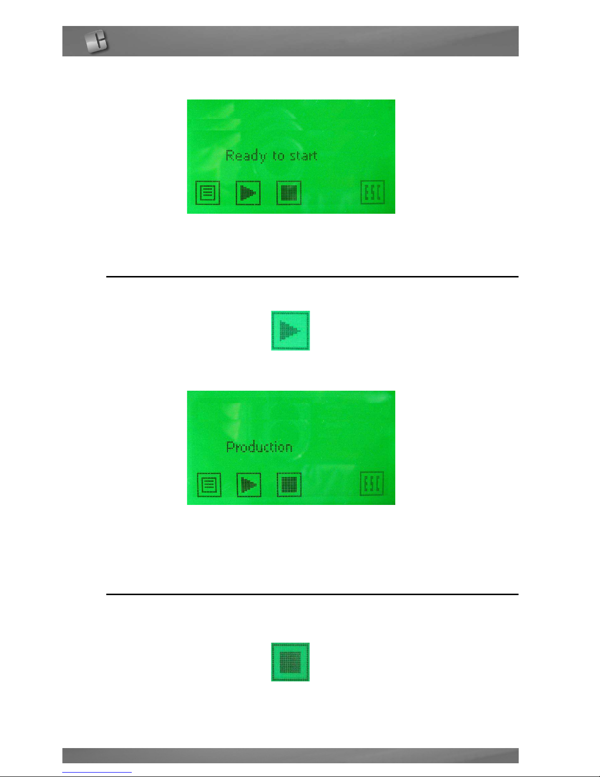
After the LOGO page is shortly displayed, the GENERATORS LIST page appears
Press on the displayed generator.
Page 24
24
The READY TO START page appears
7.5.
Nitrogen production
To start production, press the operation key START
The following page appears
7.6.
Stop the generator
At any time during production the generator can be stopped by pressing the key
STOP.
Page 25
Nitrogen Generator NiGen HF - NiGen LCMS
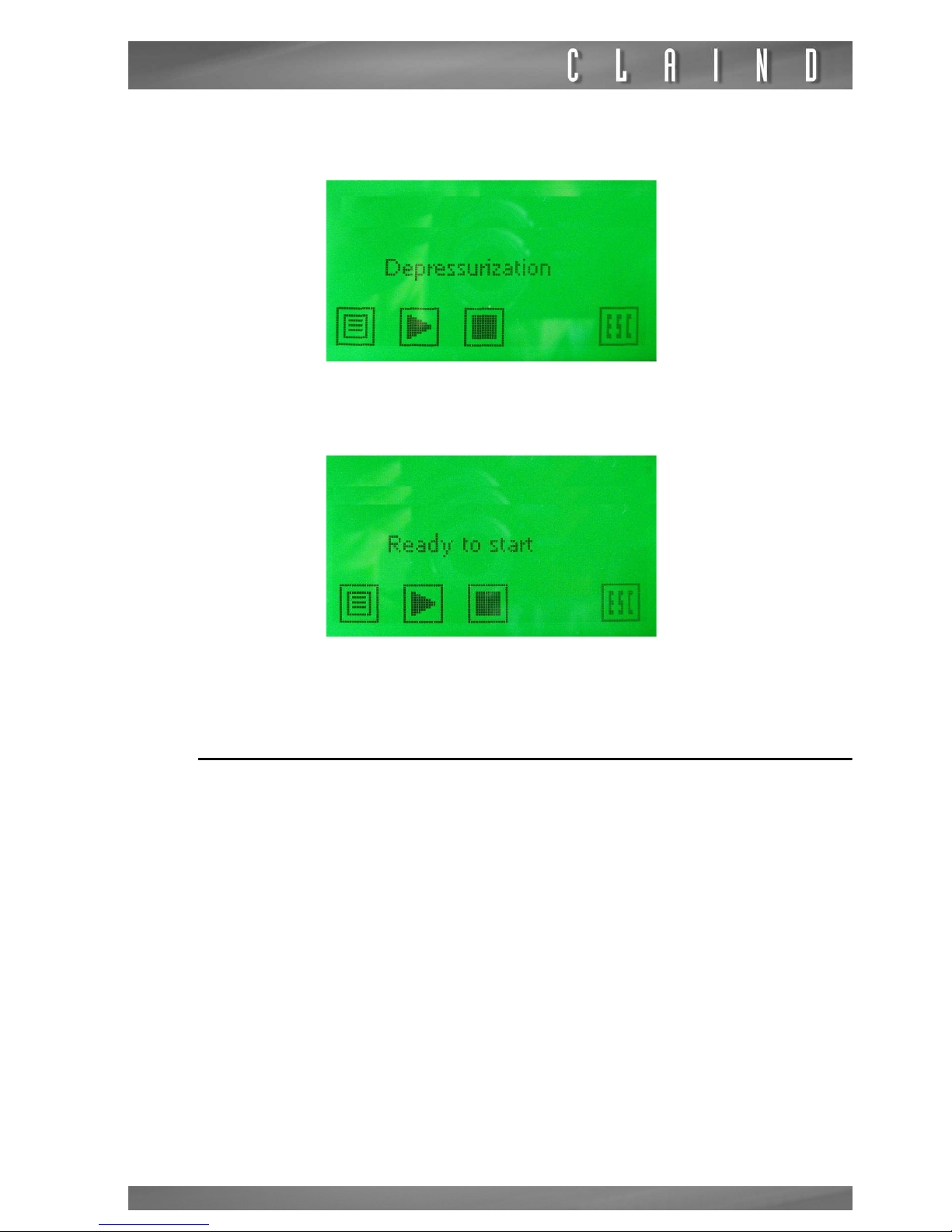
25
The generator depressurizes the molecular sieves columns, showing the following page:
When the depressurization is completed (it lasts approximately one minute), the
display shows the following page:
7.7.
Generator shutdown
After stopping the generator
(par. 7.6.)
, wait for the system to complete depressurization (approximately 1 minute), then put the main swotch on the rear of the
generator in position 0.
e
Avoid turning off the generator directly, without first stopping the production as
described in par. 7.5.
Page 26
26
7.8.
Parameter display
7.8.1.
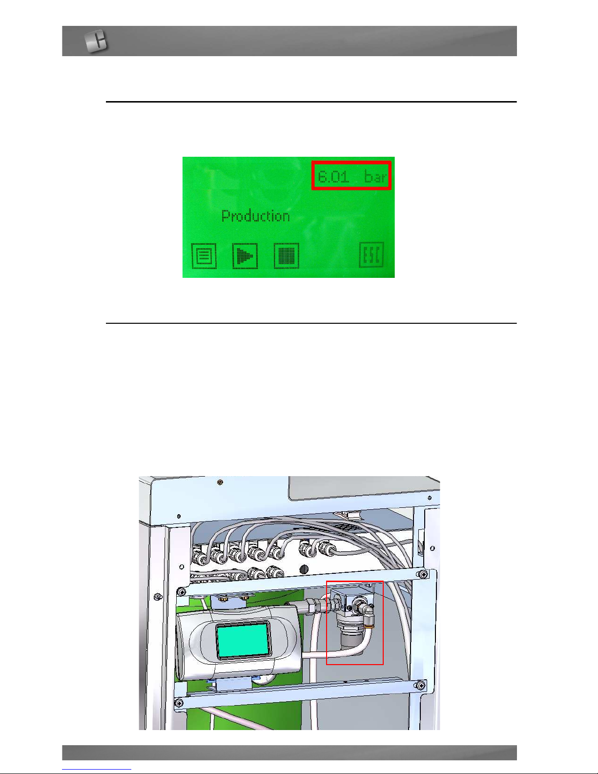
Outlet pressure display
The pressure in the outlet line is visible on the main page
7.9.
Parameter settings
e
Modifying the parameters affects plant operation. Make sure you are fully aware
of the effects of any changes before modifying the parameters
7.9.1.
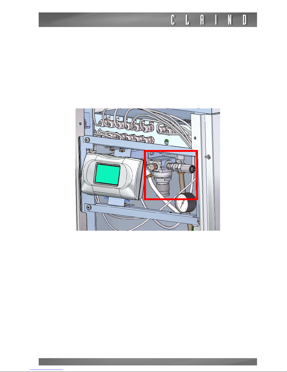
Adjusting the nitrogen delivery pressure
e
the pressure can be adjusted from 0 to 7 bar ( from 0 to 100 psi)
• remove the front panel
• identify the nitrogen delivery pressure regulator at the top right
Page 27
Nitrogen Generator NiGen HF - NiGen LCMS
27
• pull down the pressure regulator knob to release it
set the pressure by turning the knob clockwise to increase, counterclockwise to
decrease it. To visualize the outlet pressure,
par. 7.8
..
7.9.2.
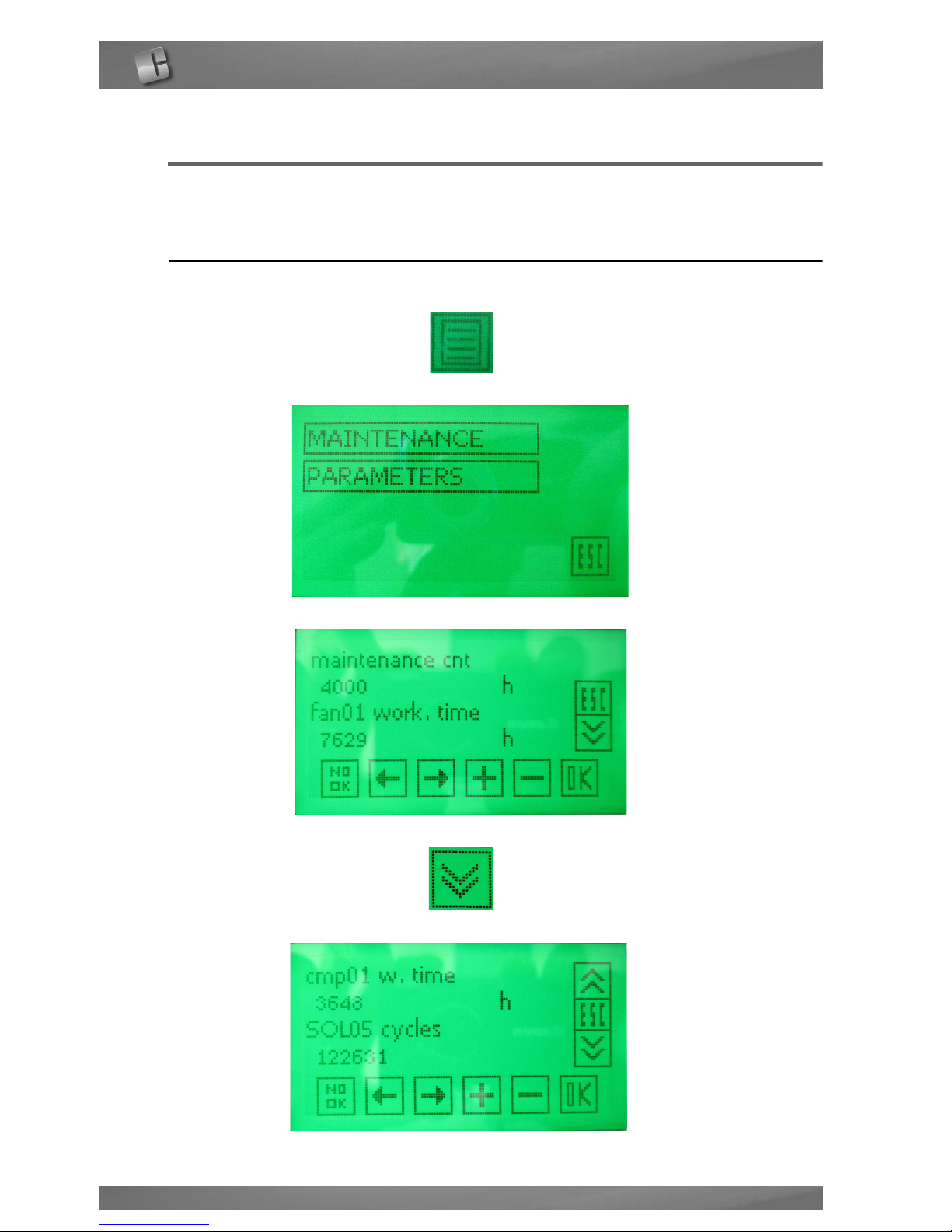
Adjusting the air outlet pressure
Only for NiGen HF-1 and NiGen LCMS 40-1
e
the pressure can be adjusted from 0 to 8 bar ( from 0 to 116 psi)
• remove the front panel
• identify the air outlet pressure regulator at the top left
• pull down the pressure regulator knob to release it
set the pressure by turning the knob clockwise to increase, counterclockwise to
decrease it.
Page 28
Maintenance
28
8.
Maintenance
The maintenance operations required on the generator are listed at
par. 8.3.
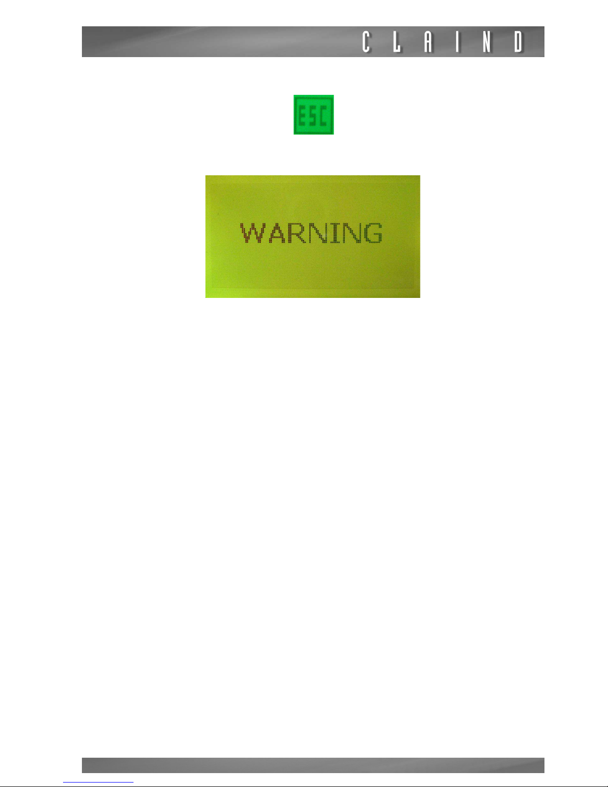
8.1.
Maintenance counters display
Press the MENU key
then press MAINTENANCE:
the following page is displayed:
scroll down the pages using the NEXT key:
he following page is displayed:
Page 29
Nitrogen Generator NiGen HF - NiGen LCMS
29
To exit this menu, press the ESC key:
e
When CNT of CMP01 reaches the setting hours of MAINTENANCE CNT, a WARNING will be displayed to recommend the related maintenance intervention.
Page 30
Maintenance
30
8.2.
Maintenance kit
The following kit for the maintenance of the generator are available. They have
to be substituted after the following time intervals. Kits are different dipending
on the model:
8.2.1.
NiGen HF-1 and NiGen LCMS 40-1
8.2.2.
NiGen HF-0, NiGen LCMS 40-0
8.2.3.
NiGen LCMS 100
Type and quantity service kit selection
Part number Description
Maintenance interval
0-4000 h 0-8000 h 0-12000 h 0-16000 h
422.93.0025
Maintenance kit
2000-4000 h
1 1 1 1
422.93.0026
Maintenance kit
6000-8000 h
1 1 1
422.93.0027
Maintenance kit
10000-12000 h
1 1
422.93.0028
Maintenance kit
14000-16000 h
1
Type and quantity service kit selection
Part number Description
Maintenance interval
0-8000 h 0-16000 h
422.93.0007 Maintenance kit 8000 h 1 1
422.93.0024 Maintenance kit 16000 h 1
Type and quantity service kit selection
Part number Description
Maintenance interval
0-8000 h 0-16000 h
422.93.0011 Maintenance kit 8000 h 1 1
422.93.0023 Maintenance kit 16000 h 1
Page 31
Nitrogen Generator NiGen HF - NiGen LCMS
31
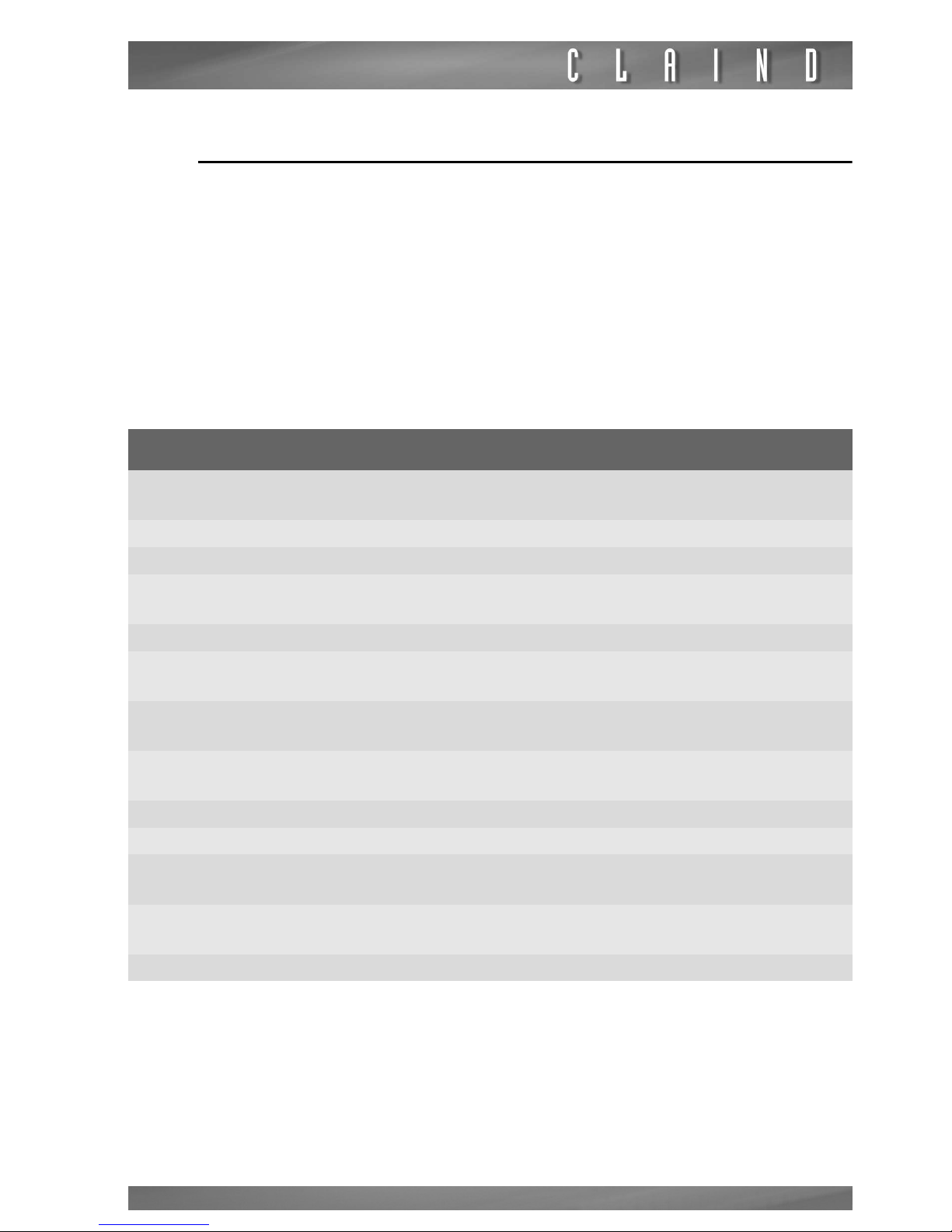
8.3.
Maintenance schedule
e
If a correct maintenance schedule is not followed, the performance of the generator may no longer be ensured and it may lead to permanent damage to the
generator. The following table specifies the frequency of the recommended
maintenance
operations, express in “working hours” of the compressor.
e
Lack of maintenance will void the warranty.
m
maintenance operations must be performed by authorized personnel
8.3.1.
NiGen HF-1 and NiGen LCMS 40-1
Components use versus maintenance plan
Component part
number
Description 2000 h 4000 h 6000 8000
R0539021 Intake air filter cartridge 1 1 1 1
R0539022 Intake air filter cap 1 1 1 1
R062999001
Silicone disk NRV
16X6mm
1 1
R0539023 Motor capacitor 1
R063399
Filter cartridge Syntesi 5
micron
1 1 1 1
R063400
Filter cartridge Syntesi
20 micron
1 1 1 1
R0539024
Dumping feet kit (3 pieces)
1 1
R061084 CMS silencer 3/8 1
R700.M4.7060 Compressed air cooler 1
R0539025
Maintenance compressor kit
R0539027
Maintenance compressor kit
Maintenance kit to be used --> 422.93.0025 422.93.0026
Page 32
Maintenance
32
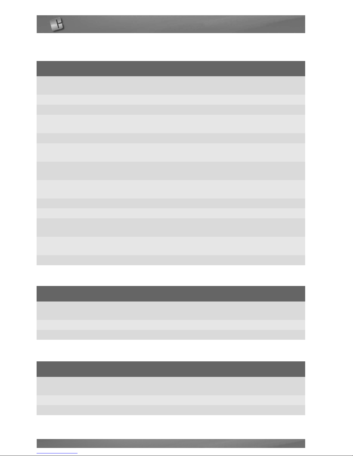
8.3.2.
NiGen HF-0, NiGen LCMS 40-0
8.3.3.
NiGen LCMS 100
Components use versus maintenance plan
Component part
number
Description 10000 h 12000 h 14000 16000
R0539021 Intake air filter cartridge 1 1 1 1
R0539022 Intake air filter cap 1 1 1 1
R062999001
Silicone disk NRV
16X6mm
1 1
R0539023 Motor capacitor 1
R063399
Filter cartridge Syntesi 5
micron
1 1 1 1
R063400
Filter cartridge Syntesi
20 micron
1 1 1 1
R0539024
Dumping feet kit (3 pieces)
1 1
R061084 CMS silencer 3/8” 1
R700.M4.7060 Compressed air cooler 1
R0539025
Maintenance compressor kit
1
R0539027
Maintenance compressor kit
1
Maintenance kit to be used --> 422.93.0027 422.93.0028
Components use versus maintenance plan
Component part
number
Description 8000 h 16000
R061084 CMS silencer 3/8” 1 1
Maintenance kit to be used --> 422.93.0007 422.93.0024
Components use versus maintenance plan
Component part
number
Description 8000 h 16000
R061080 CMS silencer 3/4” 1 1
Maintenance kit to be used --> 422.93.0011 423.93.0023
Page 33
Nitrogen Generator NiGen HF - NiGen LCMS
33
9.
Troubleshooting
9.1.
Alarms
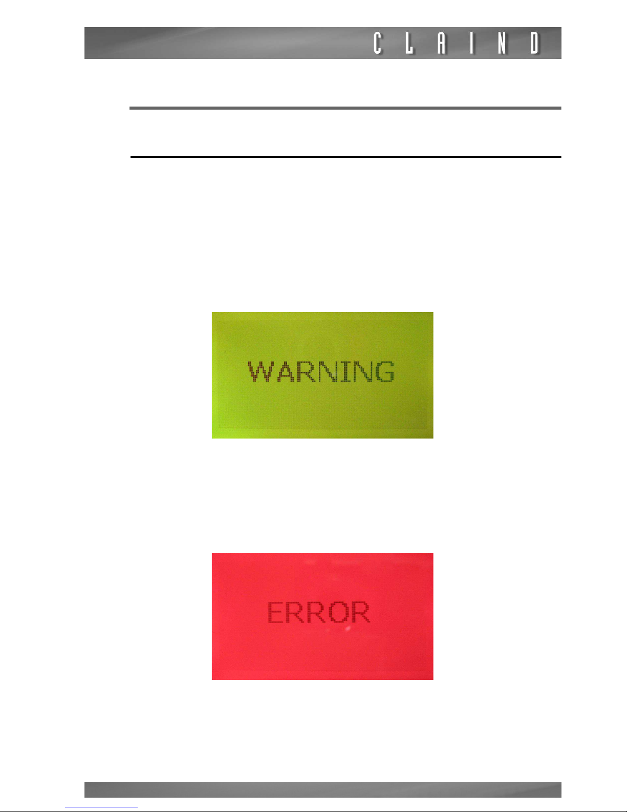
The generator informs about a malfunction or the necessity of intervention in
two different ways: warning or error .
WARNING
It indicates a condition that may require the intervention of the operator, but gas
production is not shut down.
In WARNING status:
• an acoustic signal is emitted;
• the following page is displayed
ERROR
It indicates a condition that prevents continuation of gas generation. The generator shuts down production and depressurizes the generation module.
In ERROR status:
• an acoustic signal is emitted;
• the following page is displayed
Page 34
Troubleshooting
34
9.2.
Reset and identification of an alarm
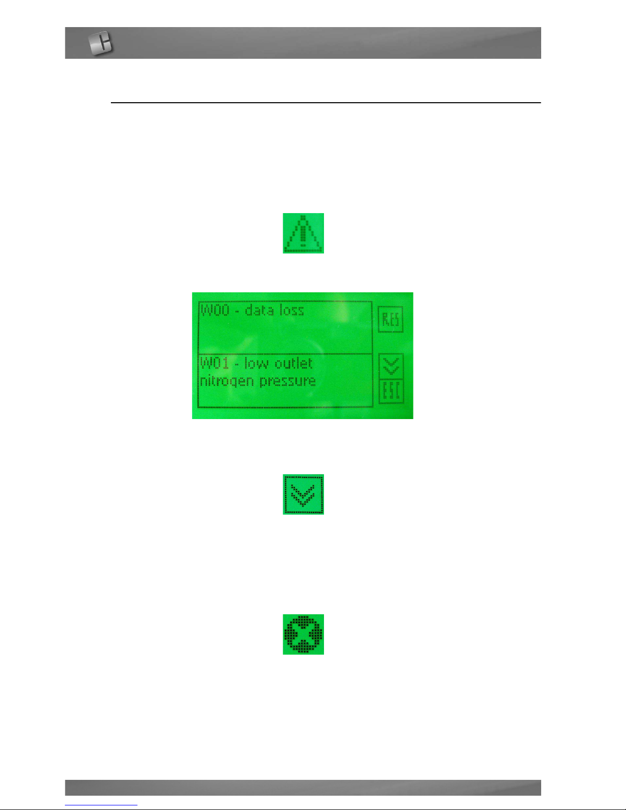
To shut off the acoustic signal, press the alarm page (WARNING yellow page or
ERROR red page)
WARNING
To visualize a warning message, press on the WARNING symbol
the following page will appear
Active warnings are those highlighted; to find the activated warning, scroll down
the pages using the NEXT key
once the warning is identified, follow the instructions in the following paragraph.
ERROR
To visualize an error message, press on the ERROR symbol
Page 35
Nitrogen Generator NiGen HF - NiGen LCMS
35
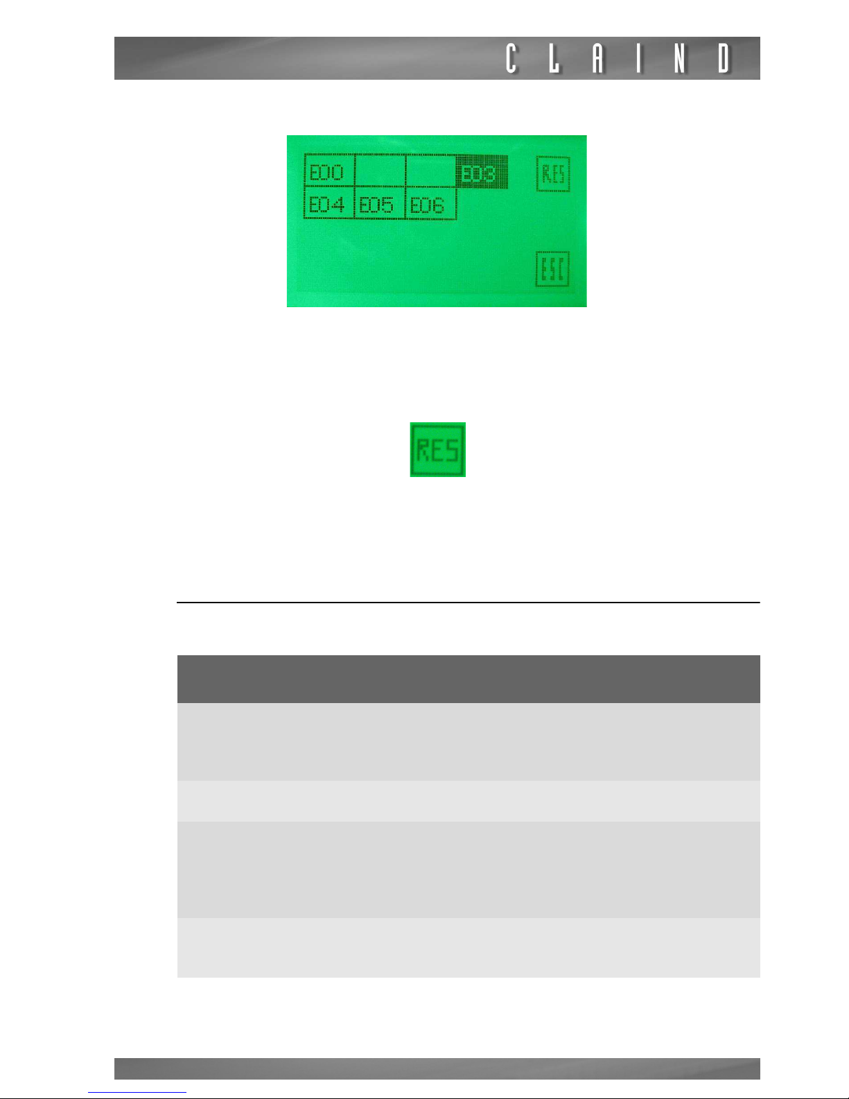
the following page will appear
Active errors are those highlighted; once the error is identified, follow the instructions in the following paragraph.
To reset the alarm, press the RESET key
9.3.
List of warnings
warning identification cause resolution
W-00 : data loss
the memory has lost the set
up values of the parameters
and has restored the default
values
contact service in order to
set the correct values of the
parameters
W-01 : low nitrogenoutlet
pressure
outlet nitrogen pressure
below threshold
reduce outlet nitrogen flow
W-02 : maintenance required
maintenance counter has
decreased to zero
check maintanance schedule; perform the requested maintenance operation;
reset related maintenance
counter
W-03 : low air outlet pressure
outlet air pressure below
threshold
(only for NiGen
LCMS 40-1 or NiGen HF-1)
reduce outlet air flow
Page 36
Troubleshooting
36
9.4.
List of errors
error identification cause resolution
E-00 type error generator not identified
assign a number to the
generator (
see Stack user’s
manual
)
E-01 low inlet pressure
inlet air pressure below minimum operative value
(only for:
NiGen LCMS 40-0; NiGen LCMS
100; NiGen HF-0)
increase inlet air pressure
E-02 high inlet pressure
inlet air pressure above maximum acceptable value
(only
for: NiGen LCMS 40-0; NiGen
LCMS 100; NiGen HF-0)
decrease inlet air pressure
E-03 compressor temperature high
compressor box temperature
above threshold
(only for:
NiGen LCMS 40-1; NiGen HF-1)
contact service
E-04 air tank pressure
high
air tank pressure above maximum threshold
(only for:
NiGen LCMS 40-1; NiGen HF-1)
contact service
E-05 air tank pressure
low
air tank pressure below minimum threshold
(only for:
NiGen LCMS 40-1; NiGen HF-1)
contact service
E-06 on chip error control board can not read data contact service
Page 37
Nitrogen Generator NiGen HF - NiGen LCMS
37
10.
Guarantee
The conditions of guarantee are as follows:
For duration of the guarantee period , see Claind’s General Sales Conditions.
The guarantee includes the cost of materials and labour.
The guarantee is EX WORKS CLAIND and therefore does not include any callout
costs for technicians to visit the client’s premises.
The guarantee covers exclusively COSTS DERIVING FROM MANUFACTURING
DEFECTS and does not include:
1. Use of non original consumable or spare sparts;
2. Damage caused by negligence or improper use of the equipment;
3. Damage caused by inadequate electric power supply;
4. Damage caused by natural catastrophes (e.g. fire);
5. Damage caused by transport;
The guarantee is rendered null and void in the event of intervention by unauthorised personnel on the equipment.
Page 38
Declaration of conformity
38
11.
Declaration of conformity
MO10MCC Emiss. 26/10/2012
',&+,$5$=,21(',&21)250,7$
(DECLARATION OF CONFORMITY)
Con la presente dichiariamo, sotto la nostra esclusiva responsabilità,
FKHO¶DSSDUHFFKLDWXUDWLSR
(By this letter we declare, under our responsibility, that the following apparatus:)
CODICE
(Part number)
VERSIONE
(Version)
DESCRIZIONE
(Descritpion)
422.02.0640
3
NiGen LCMS 40-1 115 VAC 60Hz
422.02.0650
3
NiGen LCMS 40-1 230VAC 50Hz
422.02.0660
3
NiGen LCMS 40-1 230VAC 60Hz
422.02.0710
3
NiGen LCMS 40-0
422.02.0810
3
NiGen LCMS 100-0
422.02.0440
3
NiGen HF-1 115 VAC 60Hz
422.02.0450
3
NiGen HF-1 230 VAC 50Hz
422.02.0460
3
NiGen HF-1 230 VAC 60Hz
422.02.0310 3 NiGen HF-0
alla quale questa dichiarazione si riferisce, è conforme con quanto
stabilito dalle seguenti disposizioni, in particolare:
(to which this declaration regards, is fully in conformity with the following rules:)
2014/30
UE
Direttiva compatibilità elettromagnetica
(Electromagnetic compatibility directive)
2014/35
UE
Direttiva bassa tensione
(Low voltage directive)
2014/68
UE
Attrezzatura in pressione
(Pressure equipment)
Tremezzina, 25/01/2017
Firma del legale rappresentante
(Signature of legal representative)
Giovanni Cogotzi
Via Regina 24, 22016 Tremezzina
Loc. Lenno (CO) Italy
Tel. ++39-0344-56603
Fax. ++39-0344-56627
e-mail: [email protected]
www.claind.it
Page 39
Nitrogen Generator NiGen HF - NiGen LCMS
39
12.
Notes
Page 40

Claind srl
Via Regina, 24
22016 Tremezzina Loc. Lenno (CO) - Italy
Tel +39 0344 56603
Fax +39 0344 56627
e-mail [email protected]
UM NiGen HF NiGen LCMS en J.fm
 Loading...