

Claind NiGen GC, Nigen MICRO, AirGen User Manual
User’s Manual
Nitrogen
Generator
NiGen GC
Nigen MICRO
2
Table of contents
1. Introduction 3
2. Safety 4
3. Description of the generator 6
4. Installation 11
5. Disassembly and transport 16
6. Use 17
7. Maintenance 27
8. Troubleshooting 28
9. Guarantee 32
10. Declaration of conformity 33
11. Notes 34

Nitrogen Generator NiGen GC Nigen MICRO
3
1.
Introduction
This document is intended for users of nitrogen generator models NiGen GC and
NiGen MICRO, and provides all information regarding installation, use , maintenance and guarantee.
The generator is intended to be used as a source of nitrogen gas for laboratory
applications, including gas chromatography, thermal analysis, ELSD, LCMS, sample preparation, etc.
The manual covers the following models:
As regards installation and maintenance, it is assumed that the user is familiar
with pneumatic circuit components, and in particular is aware of the safety aspects of compressed air and nitrogen.
The margin of the text contains the following symbols, indicating:
m
compulsory safety standards to be observed
c
electrical hazard
e
recommendations and important information
It is strongly recommended to carefully read all safety warnings (
par. 2.1.
) be-
fore carrying out any operation on the generator.
Serial number Model
422.02.0110 NiGen GC
422.02.0220 NiGen GC HC 115 V AC
422.02.0230 NiGen GC HC 230 V AC
422.02.0510 NiGen MICRO
Safety
4
2.
Safety
e
The unit must be installed and used in observance of the instructions in this booklet. Furthermore, use of the generator must be limited to that described in
Chapter 1 Introduction
. Failure to observe the foregoing will render the guarantee null and void and release CLAIND from all liability for direct or indirect damage or physical injury.
e
The user is responsible for asking local authorities if there are local safety regulations that are stricter than what is described in this manual.
2.1.
Warnings
m
Place the generators FAR FROM SOURCES OF HEAT
m
Place the generators in an environment PROTECTED AGAINST RAIN
AND WIND
c
NEVER OPEN the generator while it is connected to the electrical
mains: RISK OF FATAL INJURY BY ELECTROCUTION
e
Repairs and inspections must be carried out exclusively by QUALIFIED PERSONNEL: in the event of faults which cannot be resolved according to the pro-
cedures listed in the TROUBLESHOOTING chapter, contact exclusively our
authorized Technical Assistance.
e
If the generator is not to be used for a prolonged period of time, it must be depressurised (par. 6.7. and par. 6.8.).

Nitrogen Generator NiGen GC Nigen MICRO
5
2.2.
Notes on the use of nitrogen
Nitrogen is not a toxic gas, but when the percentage in the air exceeds specific
values there is a risk of asphyxia.
Therefore NEVER DIRECTLY INHALE the gas produced and avoid working in the
vicinity of a flow of nitrogen.
However, given the low quantities produced, it is sufficient that the flow of nitrogen occurs in a normally ventilated environment to avoid the risk of accumulation.
m
If the generator and the user utility are located in different rooms, the
following minimum ventilation must be provided to prevent increasing
or decreasing the oxygen content in the air:
2.3.
Safety devices
MAXIMUM PRESSURE: the control system constantly monitors the pressure.
In case of anomalous pressure, a safety valve (which operates independently of
the control system) prevents it exceeding 10.5 bar (152 psi).
MAXIMUM TEMPERATURE (
HC version only
): the purifier is fitted with an
internal catalyser, the temperature of which is constantly maintained at 420°C
To guarantee safety, a completely independent device is fitted which shuts off
power supply to the heating element when temperature values exceed 480°C
2.4.
Technical assistance
The CLAIND technical assistance can be contacted as follows:
Phone ++39 0344 56603
Fax ++39 0344 56627
Email: service@claind.it
Website: filling the form on the website www.claind.it at the “Service” section
Model
Minimum generator
room ventilation
Minimum point-of-use
room ventilation
NiGen GC
NiGen GC HC
9 Nm3/h
318 SCFH
16 Nm3/h
565 SCFH
NiGen MICRO
3 Nm3/h
106 SCFH
5 Nm3/h
177 SCFH
Description of the generator
6
3.
Description of the generator
3.1.
Equipment supplied
Unless otherwise agreed, the consignment includes:
• n°1 nitrogen generator model NiGen;
• n°1 CD user’s manual;
• n°1 applicable declarations of conformity of tank and safety valve;
• n°1 cable for the electrical mains;
• n°4 self-tapping screws;
• n°2 elastic spline;
• n°2 check pin;
• n°1 anchor plate;
• n°2 fitting for the connection of the plastic tube external diameter 6mm;
• n°1 fitting for the connection of the copper tube external diameter 1/8”.
3.2.
Technical specifications
3.2.1.
Nitrogen
(*) the flow rate is given at 20°C and 1 atm
(**) purity referred to residual oxygen
Maximum flow rate (*)
NiGen GC 0.5 Nl/min 0.5 slpm
NiGen GC HC 0.5 Nl/min 0.5 slpm
NiGen MICRO 4 Nl/min 4 slpm
Pressure
settable from 0 to
6 bar
settable from 0 to
87 psi
Purity (**)
NiGen GC up to 99.999 %
NiGen GC HC up to 99.999 %
NiGen MICRO up to 99.5 %
Nitrogen Generator NiGen GC Nigen MICRO
7
3.2.2.
Compressed air supply, specifications
(***) for further details on the air quality, see the specifications for Class 1-4-1,
ISO 8573-1
3.2.3.
Electrical requirements
3.2.4.
Pneumatic connections
3.2.5.
Electrical connections
Pressure
minimum 8 bar 116 psi
maximum 10 bar 145 psi
Capacity
NiGen GC 6 Nl/min 6 slpm
NiGen GC HC 6 Nl/min 6 slpm
NiGen MICRO 12 Nl/min 12 slpm
Particulates: maximum concentra-
tion of particles of diameter less
than 0.1 µm (***)
less than 0.1 mg/m³
Oil concentration less than 0.01 mg/m³
Humidity dewpoint under pressure less than 3°C
NiGen GC 115-230 V~ (±10%), 1 ph, 50-60Hz;
50W
NiGen GC HC
115 V~ (±10%); 60Hz; 1ph; 200W
or
230 V~ (±10%) 50Hz; 1 ph; 200W
NiGen MICRO
115-230 V~ (±10%), 1 ph, 50-60Hz;
50W
Nitrogen outlet G 1/8" female
Compressed air supply G 1/8" female
Power supply IEC320
CAN bus IN; CAN bus OUT RJ45

Description of the generator
8
3.2.6.
Dimensions
3.2.7.
Environmental requirements
3.2.8.
Noise
Width 38 cm 14.9”
Depth 53 cm 20.8”
Height 47cm 15.8” + 2.8”
Weight
NiGen GC
NiGen MICRO
37 kg 82 lbs
Weight
NiGen GC HC
41 kg 90 lbs
Installation site enclosed, indoors
Relative humidity up to 90%, no condensation
Use temperature from 5°C to 40°C
from 40°F to
100°F
Protection rating IP20
Noise level at 1 meter 60 dB(A)
Nitrogen Generator NiGen GC Nigen MICRO
9
3.3.
Generator components
3.3.1.
Front view
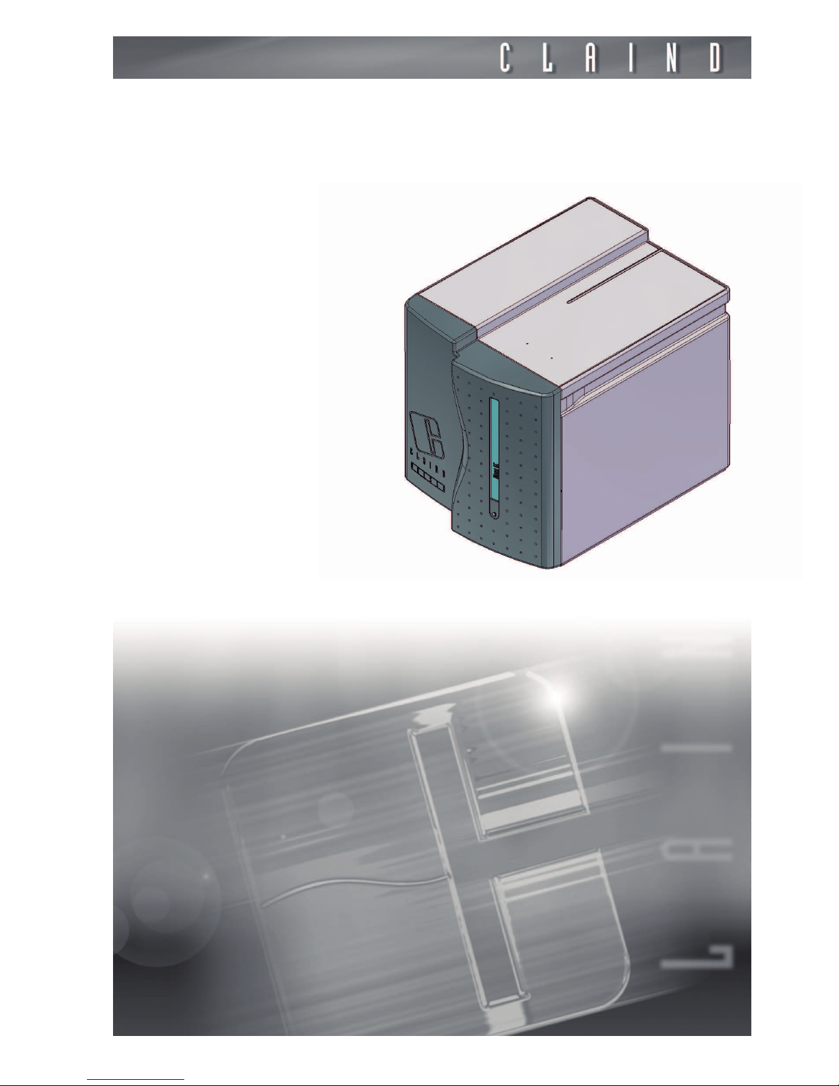
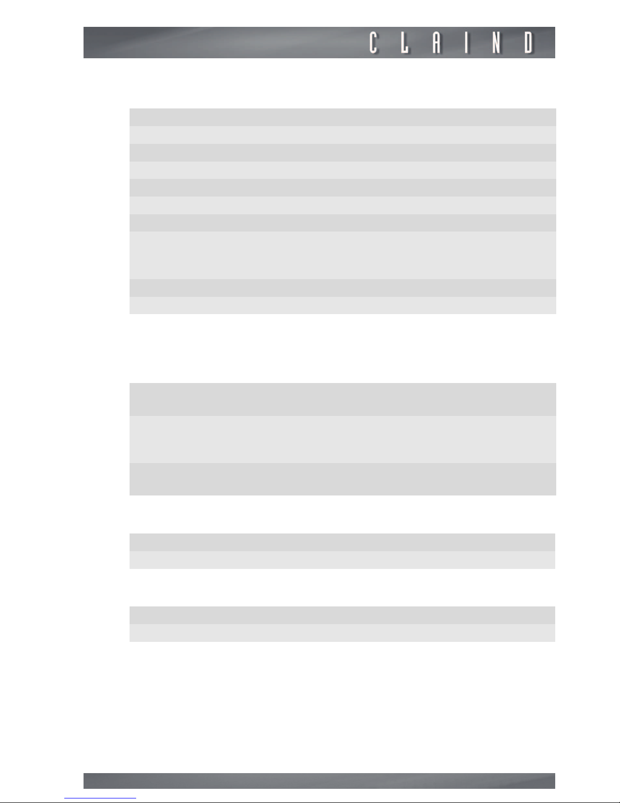
A. CPU: generator control unit; it is the user interface by way of the touch screen;
B. FRONT PANEL, removable for maintenance operations.
FIGURE 3.3.1: Front view
Description of the generator
10
3.4.
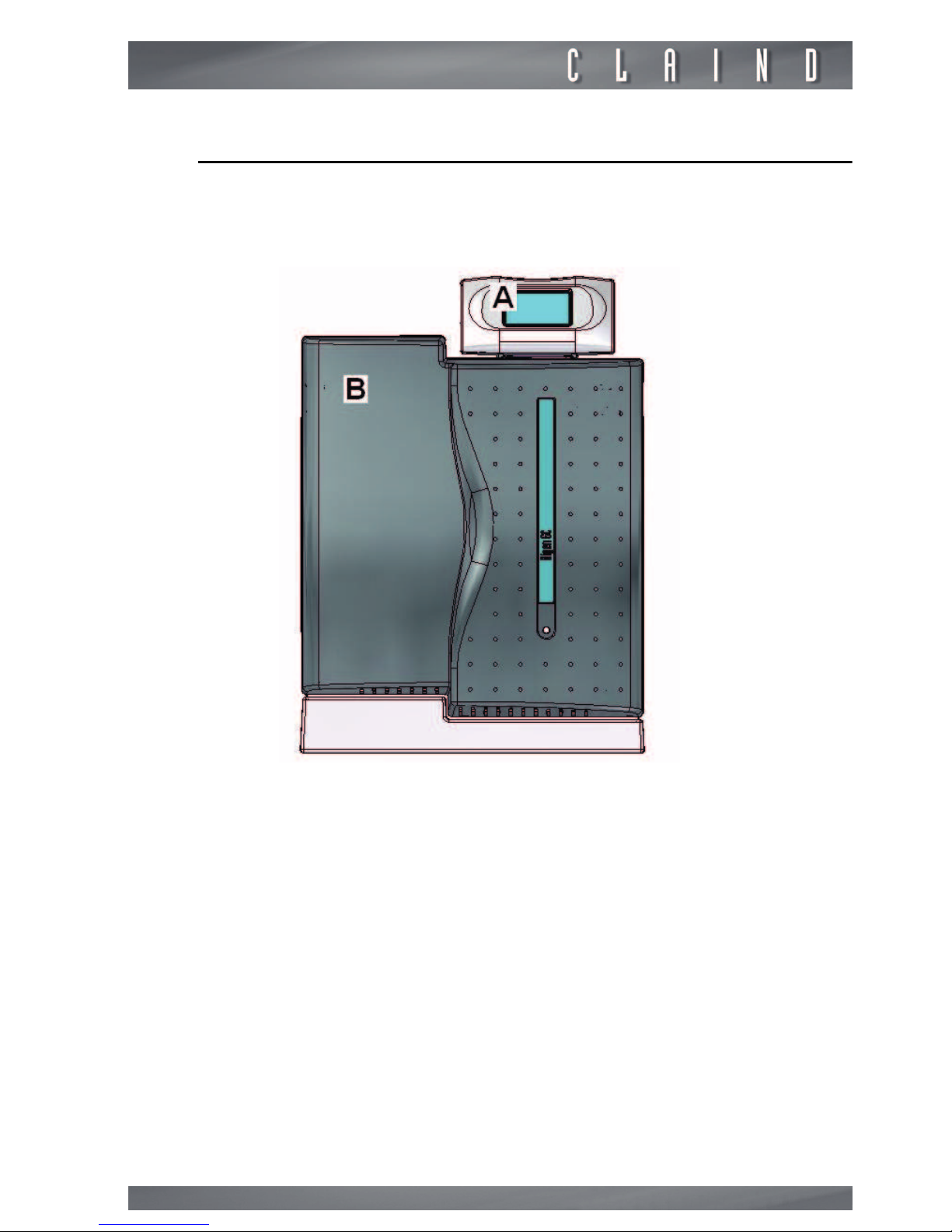
Rear view
C. AIR INLET: pneumatic connection for compressed air line inlet.
D. NITROGEN OUTLET: pneumatic connection for the generator’s nitrogen
delivery.
E. PRESSURE REGULATOR nitrogen delivery
F. CONNECTOR for electric power supply cable
G. POWER" KEY: ON-OFF switch; includes housing for the main fuse
H. CAN BUS IN for connection to CPU
I. IDENTIFICATION LABEL: states the model, serial number (SN) and electrical
specifications
J. VENTILATION GRILLE
K. CAN BUS OUT
L. CAN BUS ADDRESS (DIP switch)
FIGURE 3.3.2. Rear view

Nitrogen Generator NiGen GC Nigen MICRO
11
4.
Installation
4.1.
Installation area requirements
4.1.1.
Environment
The area where the generator is installed must meet the requirements listed under
par. 3.2.7.
m
in particular, check if ventilation is adequate. Do not install the generator into a closed cabinet with insufficient ventilation.
In regards to ventilation, refer to
par. 2.2.
4.2.
Generator positioning
4.2.1.
Packaging removal
• Open the packaging from the top
• remove the box containing the accessories
• lift the generator by grasping its side handles (two people are needed for this
operation) and set it momentarily on a flat surface
• remove the support base and place it on the desk where you plan to install the
generator.
e
It is recommended to store the packaging to ensure adequate protection when
moved in the future.
If the generator is to be installed on the tower see the attached.
4.2.2.
Positioning
Position the generator on its support base (two people are needed for this operation).
m
Ensure a clearance of at least 20cm at the rear of the generator. There
must be no potential sources of sparks in this clearance at the rear of
the generator, such as: flames, electrical contacts, hot surfaces, moving parts that can generate sparks, etc.
m
To not decrease ventilation efficiency, also ensure a clearance of at least 20cm at the front of the generator.
The generatore must be positioned on the apposite base, following foregoing instructions:
• place the base in the installation site (you can adjust the plastic feet to the desired height);
 Loading...