

Page 1
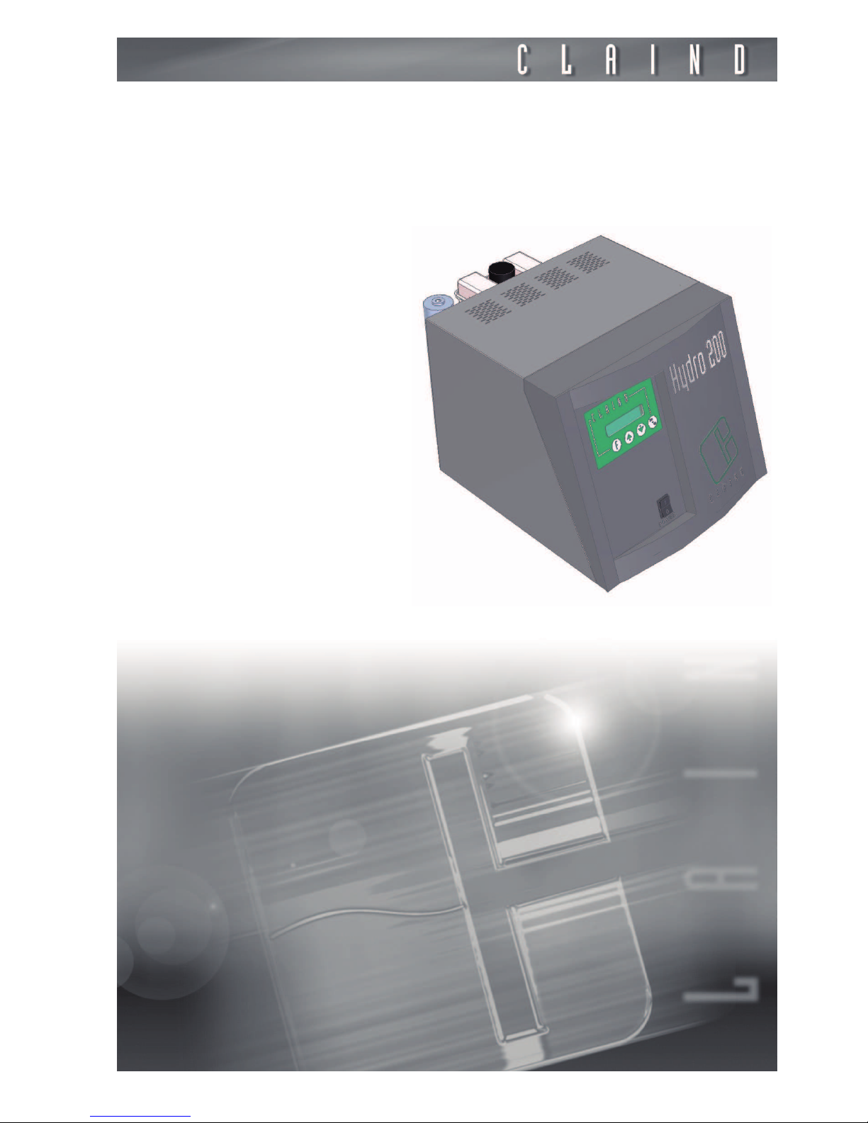
User’s manual
Hydrogen
generator
Hydro200
Page 2
2
Sommario
1. Introduction 3
2. Safety 4
3. Description of the generator 6
4. Installation 9
5. Disassembly and transport 12
6. Use 13
7. Maintenance 20
8. Troubleshooting 23
9. Guarantee 25
10. Declaration of conformity 26
11. Note 27
Page 3

Hydrogen generator Hydro200
3
1.
Introduction
This document is aimed at the User of a hydrogen generator model in the series
Hydro200, and provides all information regarding installation use and maintenance.
As regards the operations of installation and maintenance, it is presumed that
the manual user is experienced in the use of pneumatic components, and in particular is aware of all safety aspects linked to the use of hydrogen.
The margin of the text contains the following symbols, indicating:
m
compulsory safety standards to be observed
c
electrical hazard
e
recommendations and important information
It is strongly recommended to carefully read all safety warnings (par. 2.1.) before carrying out any operation on the generator.
Page 4
Safety
4
2.
Safety
The generators in this series can be installed in the vicinity of the utilities without
the requirement for classification of the surrounding area as “hazardous”, provided that all necessary measures have been taken to guarantee the maximum
safety.
The unit must be installed and used in observance of the instructions in this booklet. Failure to observe these instructions will render the guarantee null and void
and release CLAIND from all liability for direct or indirect damage or physical
injury.
2.1.
Warnings
m
Hydrogen is an extremely flammable gas that forms EXPLOSIVE MIXTURES WITH AIR. If not aware of all safety aspects linked to the use
of this gas, consult the relative safety datasheet
m
Place the generators FAR FROM SOURCES OF HEAT
m
The generator must operate with its safety guard fitted: this guarantees the correct circulation of air and prevents the formation of gas
pockets. For the same reason, NEVER PLACE OBJECTS ON THE TOP
VENTILATION GRILLE
m
Place the generators in an environment PROTECTED AGAINST RAIN
AND WIND
c
NEVER OPEN the generator while it is connected to the electrical
mains. RISK OF FATAL INJURY BY ELECTROCUTION
e
Repairs and inspections must be carried out exclusively by SPECIALIST PERSONNEL: in the event of faults impossible to solve according to one of the pro-
cedures in the TROUBLESHOOTING chapter, contact exclusively a CLAIND
technical service centre
e
If the generator is not to be used for a prolonged period of time, it must be adequately depressurised (see par. 6.4. and par. 6.5.)
Page 5

Hydrogen generator Hydro200
5
2.2.
Safety devices
MAXIMUM PRESSURE: The maximum volume of hydrogen that can be stored
in the generator is 100ml . Maximum operating pressure is 4 bar.
There is a double pressure control.
• One is a pressure sensor, via the control system, which shuts down the generator when pressure value exceeds by 0.5 bar the set value;
• The other is a pressure switch, independent from the control system, which shuts down the generator when pressure value exceed 4.5 bar;
HYDROGEN-OXYGEN MIXTURE: The formation of potentially hazardous
hydrogen-oxygen mixtures inside the generator is prevented by:
• Special electrodes (patented) for the production of hydrogen which prevent oxygen from mixing with the hydrogen.
• A forced ventilation system prevents the formation of hydrogen pockets due to
possible gas leaks. Any significant gas leaks are also indicated by the control system.
2.3.
Technical assistance
The CLAIND technical assistance can be contacted as follows:
Tel. ++39 0344 56603
Fax ++39 0344 56627
e-mail: [email protected]
Page 6

Description of the generator
6
3.
Description of the generator
3.1.
Equipment supplied
Unless otherwise agreed upon, the supply of a generator in the series Hygen200
includes:
• hydrogen generator
• User manual
• electric power supply cable (2m) with socket type IEC350-Schuko
For connection to copper pipe 1/8” comprising:
• n°1 adaptor 6MB-1/8”
• n°1 nut Swagelok 1/8”
• n°1 back ferrule Swagelok 1/8”
• n°1 front ferrule Swagelok 1/8”
For connection to steel pipe 2x1mm comprising:
• n°1 coupling 6MB for steel pipe 2x1mm
• n°5 ferrule for steel pipe 2x1mm
For connection to vent pipe comprising:
• 2m polyamide pipe 6x4mm
• n°1 ferrule for polyamide pipe 6x4mm
• n°1 nut for polyamide pipe 6x4mm
For routine maintenance comprising:
• n°1 funnel for replenishing drier
• n°1 Allen key 8mm
Page 7

Hydrogen generator Hydro200
7
3.2.
Technical specifications
3.2.1.
General
3.2.2.
Electrical
3.2.3.
Gas
Dimensions Width 40 cm
Depth 50
Height 31
Weight 19 kg
Noise <46 dB(A)
Operating temperature 5÷40°C
Protection rating IP20
Power supply voltage
115÷230 V~ (±10%); 1ph;
50÷60Hz
Max. absorption 100 V~
Maximum hydrogen flow rate 200 Nml/min
Hydrogen pressure settable from 1 to 4 bar
Page 8
Description of the generator
8
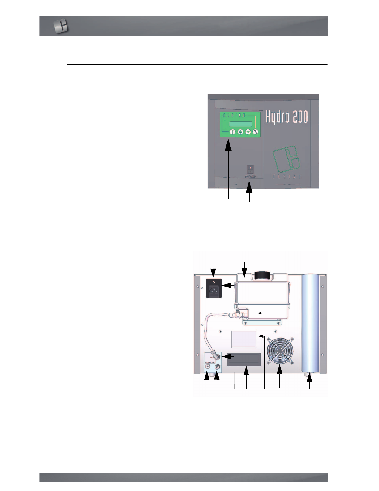
3.3.
Generator components
3.3.1.
Front view
3.3.2.
Rear view
A. ALPHANUMERIC DISPLAY AND
KEYBOARD: indicates operating status
and alarms; the four keys enable the
display and modification of operating
parameters as required
B. “POWER” KEY: ON push button
A. CONNECTOR, “jack” type for control
of external pump (optional)
B. CONNECTOR for electric power cable;
includes housing for main FUSE
C. TANK for demineralised water
D. H2 OUT: coupling for hydrogen outlet
E. O2 VENT: coupling for air vent
F. WATER: coupling for demineralised
water inlet
G. HANDLE for generator lifting
H. LABEL: stating the model, serial
number (SN) and electrical
specifications
I. GRILLE for ventilation
J. DRIER tube
A B
A B C
D E F G H I J
Page 9

Hydrogen generator Hydro200
9
4.
Installation
4.1.
Installation area requirements
4.1.1.
Humidity and dust
To avoid risks of damage to electronic components, install the generator in an
environment subject to limited relative humidity and low concentrations of dust.
The generator must also be protected against drips, rain and wind.
4.1.2.
Temperature
The ambient temperature in the generator installation area must be between
5°C and 40°C.
Install away from heat sources. Avoid direct exposure to sunlight.
4.2.
Installation procedure
4.2.1.
Step 1: remove the packaging
Remove all packaging, taking care not to damage the generator panels.
If possible, store the packaging to ensure adequate protection when moved in
the future.
Ensure that the supply is complete (see section 3.1)
4.2.2.
Step 2: position the generator
Locate an installation area that meets the specifications listed in section 4.1.
Position the generator on a laboratory bench or on a Claind generator from the
series AirToc, AirToc SL, or NitroAir.
e
Handle with care: never tilt the generator and avoid impact with obstacles.
e
Ensure a clearance of at least 20cm cm at the rear of the generator.
e
Remember never to place objects on the top panel of the generator.
4.2.3.
Step 3: fill the demineralised water tank
• locate the demineralised water tank at the rear of the generator
• disconnect the tank by means of the quick coupling at the bottom of the tank.
• remove the tank
• unscrew the cap, fill the tank to 1 cm from the top edge and refit the cap
• refit the tank and connect the quick coupling
e
Use demineralised water with electrical conductivity no higher than
Page 10

Installation
10
5µS/cm (resistivity no lower than 0.2 MΩ cm) @ 20°C
e
The generator consumes approx. 1ml (1cc) of demineralised water per litre (Nl)
of hydrogen produced
e
On request, CLAIND can supply an external pump kit (see APPENDIX), which in
command by the generator enables automatic refilling of demineralised water.
4.2.4.
Step 4: Connect the hydrogen line.
• locate the coupling H2 OUT at the rear of the generator
• remove the cap using a 8mm hex key
• From those available in the connection kit, choose the coupling most suited to
the line used. The supply comprises couplings for connection to 1/8” copper pipes or 2×1mm steel pipe
• Connect the line.
e
the hydrogen line must be able to withstand a pressure of at least 4.5 bar.
e
conserve the cap, as it is used in the event of future transport of the generator
(see chapter 5)
4.2.5.
Step 5: connect the electrical mains;
• check that the mains specifications correspond to the data on the generator dataplate
• ensure that the POWER key is set to OFF.
• Make the electrical connection using the cable supplied with the generator (type
IRC350-Schuko, length 2m)
c
For reasons of safety, the following instructions must be strictly observed.
The electrical installation must comply with current standards, in particular regarding the protection line.
c
Recommendations for correct installation:
• do not use extension leads, adaptors or multiple sockets; if necessary, replace
the plug IEC350-Schuko with a more suitable version;
• always connect the protection wire;
• the mains socket must be located in an easily accessible position.
e
If a failure in gas supply (due to a power failure, activation of an electrical safety
device, or generator fault), even temporary, is not admissible, a pneumatic panel
should be envisaged, to enable provisional activation of a reserve gas source (totally or partially automatic).
e
To ensure compliance with standards imposed by the Machinery directive, the
start-up of the generator after electrical power supply is restored cannot normally be automatic, and should be manually activated by the operator.
Page 11

Hydrogen generator Hydro200
11
e
If automatic start-up of the generator is necessary, this command should be entered in the set-up program
4.2.6.
Step 6: Connect the vent hose
• locate the outlet O2 VENT at the rear of the generator
• remove the plastic cap using a 12mm hex key
The O2 VENT outlet enables the oxygen (produced in parallel to the generation
of hydrogen) to be released into the atmosphere. As the released oxygen may
in some phases contain traces of electrolyte, the vent should be conveyed as follows:
• connect the polyamide pipe 6x1 mm (supplied with the generator) and route the
other end of the pipe (shortened if necessary) to a small collection tray placed
at a lower level than that of the generator.
e
avoid obstructing the vent: during use, the end of the polyamide pipe 6x1 mm
opposite the generator must never by closed off or immersed in the liquid.
e
conserve the cap, as it is used in the event of future transport of the generator
(see chapter 5)
4.2.7.
Step 7: set the mode parameters
In this phase the mode parameters should be checked (and modified if required), which enable the selection of the language for message display and selection of a number of operating modes, including the method for demineralised
water refilling.
For details, refer to section 6.7.1.
4.3.
Packaging disposal
All packaging materials used are compatible with the environment and may be
stored without risk, or disposed of and recycled in accordance with local legislation governing classified waste collection.
However, when possible, it is recommended to store the packaging to ensure
adequate protection when moved in the future.
Page 12
Disassembly and transport
12
5.
Disassembly and transport
5.1.
Disassembly
• Stop the generator (see par. 6.4.).
• Wait for depressurisation.
• Switch off the generator (see par. 6.5.).
• Disconnect the electric power cable;
• Close the valves downline of the generator and detach the pneumatic connections.
• Seal off outlet H2 OUT using the original cap
• Seal off outlet O2 VENT using the original cap
• Empty the demineralised water tank
e
missing caps on the outlets H2 OUT and O2 VENT can cause serious damage to
the generator and packaging during transport.
5.2.
Transport
If conserved, use the original packaging; otherwise use a pallet of adequate dimensions to hold the generator, affixing instructions in visible locations, such as:
THIS WAY UP, FRAGILE
Page 13
Hydrogen generator Hydro200
13
6.
Use
6.1.
Keyboard and display
KEYBOARD
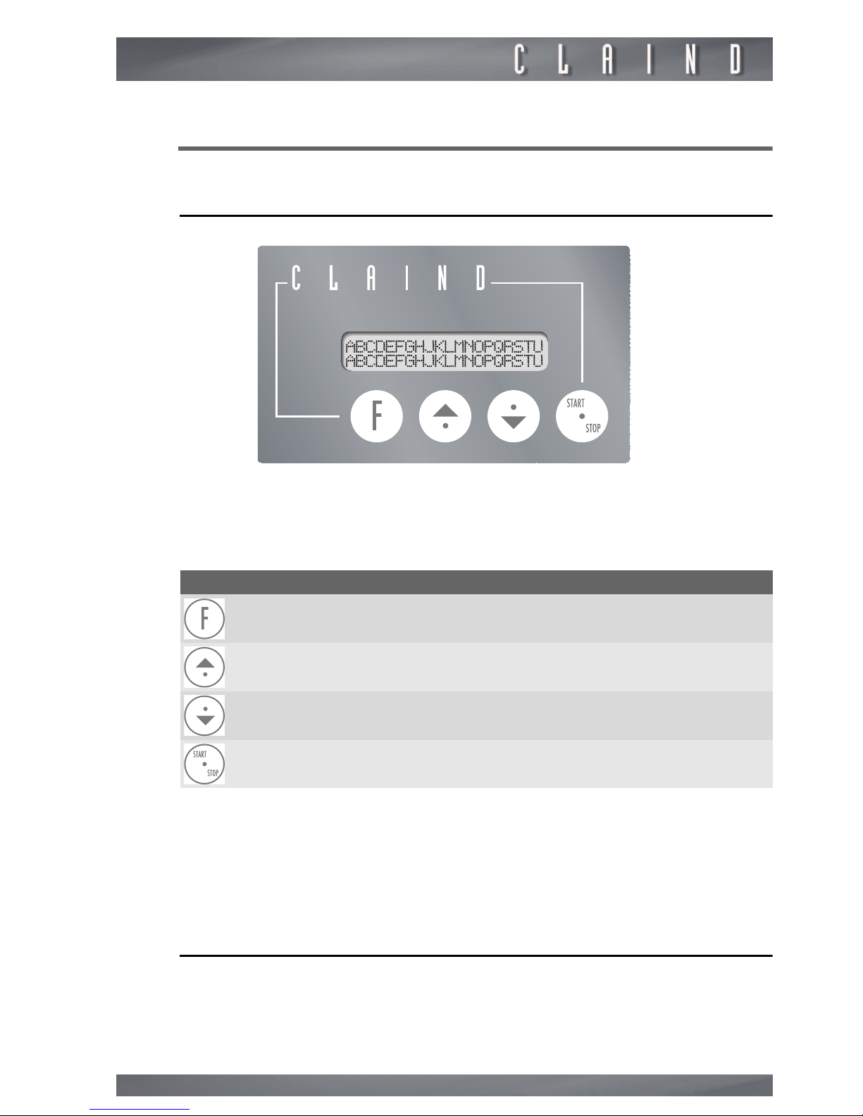
The keyboard on the front panel of the generator enables the user to interact
with the generator, i.e. give specific commands or display and set parameters.
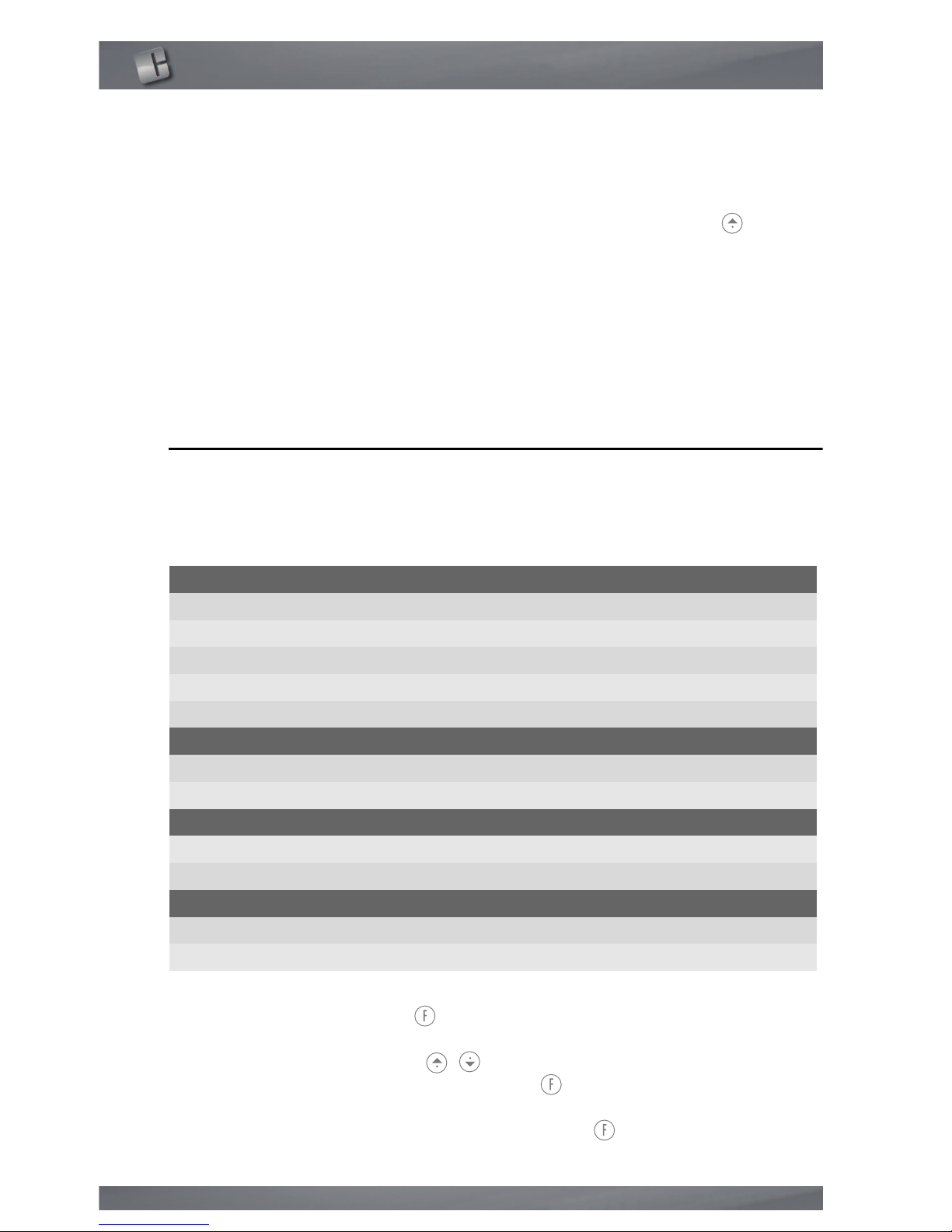
The table shows the function of the various keys:
DISPLAY
The display comprises 2 lines each of 20 characters
Usually the top line displays the functions or parameters and the lower line displays the relative status and values
If the message exceeds 20 characters, the text scrolls on display.
6.2.
Generator start-up
To switch on the generator, press the black key “POWER” at the front of the generator.
Key Function
Function Selects a generator function
Cursor Increases the selected value
Cursor Decreases the selected value
Operation Starts or stops the generator
Page 14
Use
14
The display illuminates and, after a few seconds, a depressurisation cycle is started automatically. During this phase, lasting maximum 60 seconds, the following
message is displayed:
WAIT…
DEPRESSURISATION IN PROGRESS
At the end of depressurisation, the following message is displayed:
GENERATOR READY
In this condition, the generator is ready to receive the production start-up command (see par. 6.3.) or shutdown command (see par. 6.5.).
6.3.
Hydrogen production
When the generator has completed the preparation phase (par. 6.2.) and the
message
GENERATOR READY
is displayed, hydrogen production can be
started up as follows:
Press the operation key START/STOP.
The production cycle is started up and the following message is displayed:
PRODUCTION
X.XX bar YYY Nml/min
where:
X.XX
= hydrogen pressure, expressed in
bar
Y.YY
= instant quantity of hydrogen produced, expressed in
normal millilitres
per minute
6.4.
Stop the generator
At any time during production the generator can be stopped by pressing the key
START/STOP.
Depending on the phase activated, the generator starts to depressurise immediately, or awaits conclusion of the production cycle before activating depressurisation.
During depressurisation, which usually lasts from 30 to 60 seconds, the following
message is displayed:
WAIT…
DEPRESSURISATION IN PROGRESS
Page 15

Hydrogen generator Hydro200
15
e
NOTE: if a production block alarm is active, the START/STOP key is disabled
At the end of depressurisation, the following message is displayed:
GENERATOR READY
There are then two alternatives:
1. Switch off the generator by pressing the POWER key (see par. 6.5.);
2. resume the gas production by pressing the key START-STOP (see par. 6.3.)
Page 16
Use
16
6.5.
Generator shutdown
6.5.1.
Correct shutdown
Correct shutdown of the generator starts from the condition of
GENERATOR
READY
. par. 6.4. describes how to reach this condition.
Set the "POWER" key (black) to OFF to turn off the generator.
6.5.2.
Incorrect shutdown
Avoid turning off the generator directly, without first shutting down as described
in par. 6.4.
However, this may occur inadvertently or due to a power failure. In this case, on
subsequent generator restart, the following message is displayed:
WARNING
INCORRECT SWITCH OFF
To shut off the alarm, press the function key .
6.6.
Parameter display
See also flow chart in APPENDIX
6.6.1.
Hydrogen and oxygen pressure display
During production, the main menu displays the message
PRODUCTION
.
For more information on generator status, press the up arrow key . The following page is displayed:
H2 O2
X.XX bar Y.YY bar
where:
X.XX
= hydrogen compartment pressure bar
Y.YY
= oxygen compartment pressure bar
The values are updated continuously to verify correct operation
of the generator
To exit this page and return to the main menu press up arrow key .
6.6.2.
Maintenance counters display
From the main menu (
PRODUCTION
), press the down arrow key :
The following information is displayed in sequence (approx. every 5 seconds)
Page 17

Hydrogen generator Hydro200
17
GENERATOR RUNNING TIME
XXXXX h YY min
PRODUCED HYDROGEN QUANTITY
XXXXX litres
DRIER AUTONOMY
XXXXX litres
ORDINARY MAINTENANCE
XXXXX h YY min
e
DRIER AUTONOMY displays, in countdown mode, the litres of hydrogen that can
be produced before the drier cartridge requires replacement (see Maintenance
chapter)
ROUTINE MAINTENANCE displays, in countdown mode, the operating hours remaining before a general overhaul is required (recommended) for the generator.
To exit this page and return to the main menu press up arrow key .
6.6.3.
Mode parameter display
From the main menu (
PRODUCTION
), press the down arrow key twice.
The following information is displayed in sequence (approx. every 5 seconds) regarding the set operating modes:
PRODUCTION RESTARTED AFTER INCORRECT
SHUTDOWN
Manual/Automatic
INCORRECT SWITCH OFF ALARM
Enabled/Disabled
Page 18
Use
18
INTERNAL TANK WATER REFILLING
From external tank/From external pump (optional)
To exit this page and return to the main menu press up arrow key .
e
The default values are as follows:
PRODUCTION RESTART... = Manual
...SWITCH OFF ALARM = Enabled
...REFILLING = From external tank
When modifications to these values are required (e.g. for use of the external
pump), follow the instructions in section 6.7.1.
6.7.
Parameter settings
6.7.1.
Editing mode parameters
These parameters select the operating mode of the generator, They comprise:
For access to these parameters, the generator must be switched on by pressing
and holding the Function key for a few seconds.
The data will be displayed in sequence as shown in the table above.
To modify, use the arrow keys .
To acquire the set value, press and hold key and press an arrow
key; this confirms the value and moves to the next parameter.
To exit this menu, press and hold the Function key for a few seconds.
Language of messages
Italian
English
German
French
Spanish
Production restart after incorrect switch off
Manual
Automatic
Incorrect switch off alarm
Enabled
Disabled
Internal tank watyer refilling
From external tank
From external pump
Page 19

Hydrogen generator Hydro200
19
6.7.2.
Hydrogen delivery pressure settings
The default set-point for hydrogen pressure is 1 bar. To set the operating pressure to the required value (from 1 bar to 6 bar), proceed as follows:
From the main menu (
PRODUCTION
), press function key : to display the
following:
HYDROGEN PRESSURE SET-POINT
X.XX bar
To modify the value, use arrow keys .
To acquire the set value, press and hold key and press the up arrow key .
To exit this menu, press and hold the Function key for a few seconds.
6.7.3.
Editing maintenance parameters
See Maintenance section.
Page 20
Maintenance
20
7.
Maintenance
To facilitate observance of adequate scheduled maintenance by the user, the generator is equipped with a list of components subject to wear, for which, during
the test phase, a working interval is set.
During operation this time interval decreases through to expiry, at which point
there is an automatic request for maintenance.
7.1.
Expiry warnings
During production, if the estimated autonomy of a device expires, a message is
displayed, an example of which is shown below
.
WARNING
FILTER IN EXPIRY PHASE
To acquire the message, press function key . The message is then removed
to proceed with normal operation.
On subsequent restart the generator requests whether the maintenance has
been performed, with display of the following message:
SCHEDULED MAINTENANCE OF FILTER COMPLETE?
NO
Press the up arrow key ” to select the answer “YES” or “NO” consecutively.
After selecting the answer, to acquire the message, press the function key .
If the answer is “NO”, the message is displayed again on subsequent restart,
while if “YES”, the new work time for the component is set (that set on start of
the count) for future maintenance.
If an incorrect shutdown alarm is displayed on activation of the generator, this
procedure is disabled; it will be available for subsequent start-up.
7.2.
Maintenance schedule
To maintain generator efficiency and reduce the risks of faults, strictly observe
the recommended maintenance schedule.
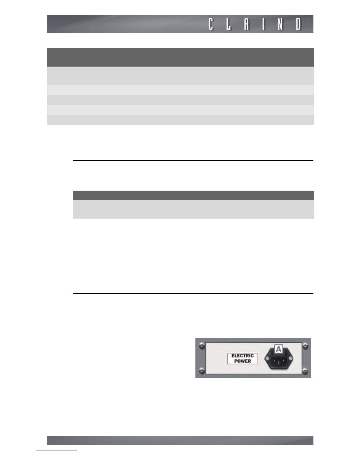
The following table specifies the frequency of the recommended maintenance
operations:
Page 21
Hydrogen generator Hydro200
21
The parts are available at CLAIND.
7.3.
Consumables list
The following table summarises the consumable parts available at
CLAIND.
In the purchase order, specify the model and serial number of the generator.
Consumables have to be substituted by the customer, because the substitution
is frequent and the operation is simple.
m
Never perform maintenance operations with the power supply connected or with the generator switched on.
7.4.
Main fuse
The generator is protected by means of a fuse located in the electric power socket.
For replacement proceed as follows:
Component
part number
Maintenance operation Operation frequency
710.07.2701 Drier replacement
every 20,000 litres of H2 produced
710.04.2123 Replace of Solenoid valve HDV/HVV every 1 year
710.04.2122 Replace of Solenoid valve OVV every 1 year
- Cleaning fan every 1 year
- General overhaul every 1 year
Description
PACK OF 1 DRIER RECHARGE FOR SERIES Hydro200
code number: 710.07.2701
• Remove the power cable from the socket
• Extract the fuse box A from the socket
• Replace the faulty fuse
• Refit the box and cable in the socket
• The generator can now be restarted.
Page 22
Maintenance
22
7.5.
Drier replacement
• Turn off the generator as described in
par. 6.4. Stop the generator and par.
6.5. Generator shutdown
• Disconnect the electric power cable
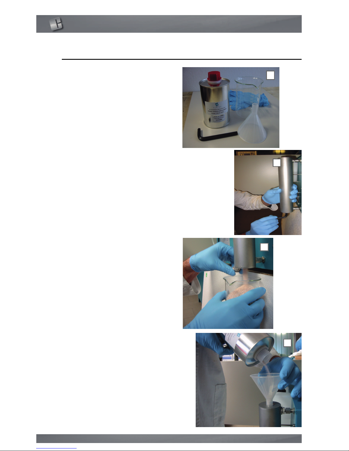
• Prepare the required material (figure
A):
- a drier recharge
- 8mm Allen key
- connection container (approx. 500
ml)
- funnel
• Loosen the lower cap by means of the
8mm Allen key(figure B)
• Remove the cap and drain the contents of the drier hose into the collection
container (figure C)
• Refit the lower cap by means of the
8mm Allen key
• Remove the top cap
• Pour the contents of the drier recharge
into the drier hose by means of the
funnel (figure D)
• Refit the top cap by means of the Allen
key
e
To avoid exposing the drier to humidity in the ambient air, open the recharge cartridge only at the time of
transfer and close the drier hose as
soon as recharging is complete
B
A
C
D
Page 23

Hydrogen generator Hydro200
23
8.
Troubleshooting
8.1.
Alarms
There are two possible alarms:
WARNING: indicates an anomalous condition that may require intervention of
the operator, but gas production is not shut down.
GENERATOR FAULT or GENERATION STOP: indicates an condition that prevents continuation of gas production. In this case the generator shuts down production. Therefore the generator must be shut down, after which eliminate the
cause and restart the generator.
In any event, the alarm is shown on display and the siren is activated.
To shut off the acoustic signal, press function key .
The possible alarms on this generator model are:
• Hydrogen consumption too high
• Water reserve active - Water reserve empty
• Condensation drain failed
• Drier lifetime expiring
• Ordinary maintenance is suggested
• Incorrect Switch off
The following section lists the causes and actions to be taken in the event of the
alarms. If an alarm is activated not listed below, contact CLAIND technical assistance.
8.1.1.
Hydrogen consumption too high alarm
The generator is unable to maintain the set pressure level.
To shut off the alarm, press function key .
• Check whether the flow rate of hydrogen received by the generator exceeds the
production capacity of the latter.
• Check whether there are leaks along the hydrogen line between the generator
and utility.
NOTE: this alarm is initially displayed as a WARNING, and production continues
for a few minutes. If the condition of excessive consumption persists, the alarm
becomes GENERATION STOP, with shutdown of gas production.
Page 24

Troubleshooting
24
8.1.2.
Water reserve alarm
The level of demineralised water in the generator has fallen below the minimum
level.
To shut off the alarm, press function key .
• Fill the external tank with demineralised water
NOTE: this alarm is initially displayed as a WARNING, and production continues
for a few minutes. If the water reserve condition persists, the alarm becomes
GENERATION STOP, with shutdown of gas production.
8.1.3.
Condensation drain failed alarm
The automatic condensate drainage procedure in the generator has not been
completed correctly.
This may occur when the generator is started up after a prolonged period of disuse.
To shut off the alarm, press function key .
• Perform the shutdown and restart procedures several times (maximum 4) as described in sections 6.5.1 and 6.2.
• If the alarm persists, contact Claind technical assistance.
8.1.4.
Drier lifetime expiring alarm
The estimated lifetime of the drier material has expired.
To shut off the alarm, press function key .
The generator continues production but maintenance is recommended (drier replacement) as described in section 7.3.
To reset the counter related to this maintenance operation, refer to section 7.1
8.1.5.
Ordinary maintenance suggested alarm
More than 10,000 hours of operation have passed since the last general overhaul.
To shut off the alarm, press function key .
The generator continues production but a general overhaul is recommended as
soon as possible, to be performed by a specialised CLAIND technician.
To reset the counter related to this maintenance operation, refer to section 7.1
8.1.6.
Incorrect switch off alarm
For details, refer to section 6.5.2.
Page 25

Hydrogen generator Hydro200
25
9.
Guarantee
The conditions of guarantee are as follows: 12 MONTHS as of the date of installation, but NO MORE THAN 14 MONTHS as of the date of delivery.
The guarantee includes the cost of materials and labour.
The guarantee is EX WORKS CLAIND and therefore does not include any callout
costs for technicians to visit the client’s premises.
The guarantee covers exclusively COSTS DERIVING FROM MANUFACTURING
DEFECTS and does not include:
1. Damage caused by negligence or improper use of the equipment.
2. Damage caused by inadequate electric power supply.
3. Damage caused by natural catastrophes (e.g. fire).
4. Damage caused by transport.
5. Damage caused by compressed air with inadequate properties.
The guarantee is rendered null and void in the event of intervention by unauthorised personnel on the equipment.
Page 26
Declaration of conformity
26
10.
Declaration of conformity
MO10MCC Emiss. 18/12/2013
KONFORMITÄTSERKLÄRUNG
(DECLARATION OF CONFORMITY)
Hiermit erklären wir unter alleiniger Verantwortung, dass das Gerät:
(By this letter we declare, under our responsibility, that the following apparatus:)
TEILENUMMER
(Part number)
VERSION
(Version)
BESCHREIBUNG
(Description)
423.04.0060
0 Hydro200
auf welches sich diese Erklärung bezieht, den folgenden Bestimmungen
entspricht, im Besonderen:
(to which this declaration regards, is fully in conformity with the following rules:)
2014/30
EU
Richtlinie über elektromagnetische Verträglichkeit (EMV)
(Electromagnetic compatibility directive)
2014/35
EU
Niederspannungsrichtlinie (NS)
(Low voltage directive)
2014/34
EU
Europäische Richtlinie über Geräte- und Schutzsysteme zur
Verwendung in explosiongefährdeten Bereichen (ATEX)
Gruppe II Kategorie 3.
(European directive concerning equipment to be used in potentially explosive atmosphere.
Group II category 3).
Tremezzina, 20/04/2016
Unterschrift des Rechtsvertreters
(Signature of legal representative)
Giovanni Cogotzi
Via Regina 24, 22016 Tremezzina
Loc. Lenno (CO) Italy
Tel. ++39-0344-56603
Fax. ++39-0344-56627
E-Mail: [email protected]
www.claind.it
Page 27

Hydrogen generator Hydro200
27
11.
Note
Page 28

Claind srl
Via Regina, 24
22016 Tremezzina Loc. Lenno (CO) - Italy
Tel +39 0344 56603
Fax +39 0344 56627
e-mail [email protected]
Hydro200 eng Rev3.fm
 Loading...