

Page 1
Series
WS1 & WS1 CD Matrix
1” & 1.25” Control Valve
with Fully Adjustable Cycles
Operation and Instruction Manual
Page 2

Page 3

Table of Contents
Installation ..............................................................................................................................................4
Specification Table..................................................................................................................................5
Start-up Instructions ..............................................................................................................................6
Filter Instructions ....................................................................................................................................7
Softener Set-up ....................................................................................................................................11
Softener Setting Options ......................................................................................................................13
Filter System Set-up ............................................................................................................................14
Installer/User Display Settings ............................................................................................................17
Installation ............................................................................................................................................23
Service Instructions ..............................................................................................................................25
Parts & Drawings..................................................................................................................................30
Troubleshooting Procedures ................................................................................................................43
Notes ....................................................................................................................................................45
WS1 CD Matrix Control Programming Manual ..............................................................................46-67
Page 3
Page 3
Page 4

Introduction
This manual is about a control valve to be used on water softeners or water filters. The manual is designed to aid water treatment
equipment manufacturers in the selection of the various control valve options. Information in this manual is different than what is
needed for installation and servicing of a particular water treatment system. This manual is not intended to be used as a manual for a
complete water softener or filter. Certain parts of the manual will serve as aids to manufacturers in the writing and layout of the
manuals for installers and service personnel.
The following general warnings and the specifications in Table 1 must appear in the OEM’s System Manual.
The control valve, fittings and/or bypass are designed to accommodate minor plumbing misalignments but are not designed to
support the weight of a system or the plumbing.
Do not use Vaseline, oils, other hydrocarbon lubricants or spray silicone anywhere. A silicone lubricant may be used on black
o-rings but is not necessary. Avoid any type of lubricants, including silicone, on the clear lip seals.
The nuts and caps are designed to be unscrewed or tightened by hand or with the special plastic wrench. If necessary a pliers can be
used to unscrew the nut or cap. Do not use a pipe wrench to tighten or loosen nuts or caps. Do not place a screwdriver in the slots on
caps and/or tap with a hammer.
Do not use pipe dope or other sealants on threads. Use Teflon tape on the threaded inlet, outlet and drain fittings. Teflon tape is not
necessary on the nut connection or caps because of o-ring seals.
After completing any valve maintenance involving the drive assembly or the drive cap assembly and pistons, press and hold NEXT
and REGEN buttons for 3 seconds or unplug power source jack from the printed circuit board (black wire) and plug back in. This
resets the electronics and establishes the service piston position. The display should flash all wording, then flash the software version
and then reset the valve to the service position.
All plumbing should be done in accordance with local plumbing codes. The pipe size for the drain line should be a minimum of ½”.
Backwash flow rates in excess of 7 gpm or length in excess of 20’ require ¾” drain line.
Solder joints near the drain must be done prior to connecting the drain line flow control fitting. Leave at least 6” between the drain
line control fitting and solder joints when soldering pipes that are connected on the drain line control fitting. Failure to do this could
cause interior damage to the drain line flow control fitting.
When assembling the installation fitting package (inlet and outlet), connect the fitting to the plumbing system first and then attach
the nut, split ring and o-ring. Heat from soldering or solvent cements may damage the nut, split ring or o-ring. Solder joints should
be cool and solvent cements should be set before installing the nut, split ring and o-ring. Avoid getting primer and solvent cement on
any part of the o-rings, split rings, bypass valve or control valve.
Plug into an electrical outlet. Note: All electrical connections must be connected according to local codes. (Be certain the outlet is
uninterrupted.)
Install grounding strap on metal pipes.
Page 4
Page 5

Table 2 contains a summary of specifi cations for the control valve and bypass valve.
Table 1
Specifi cations which must be included in OEM’s Manual
Table 2
Quick Reference Specifi cations
Minimum/Maximum Operating Pressures 20 psi (138 kPa) -125 psi (862 kPa)
Minimum/Maximum Operating Temperatures 40°F (4°C) - 110°F (43°C)
AC Adapter:
Supply Voltage
Supply Frequency
Output Voltage
Output Current
U.S. International
120 V AC 230 V AC
60 Hz 50 Hz
12 V AC 12 V AC
500 mA 500 mA
No user serviceable parts are on the PC board, the motor, or the AC adapter. The means of
disconnection from the main power supply is by unplugging the AC adapter from the wall.
Service fl ow rate 1" (includes bypass and meter) 27 gpm (102.2 lpm) @15 psig (103 kPa) drop
Backwash fl ow rate 1" (includes bypass) 27 gpm (102.2 lpm) @25 psig (172 kPa) drop
Service fl ow rate 1.25" (includes meter) 34 gpm (128.7 lpm) @15 psig (103 kPa) drop
Service fl ow rate 1.25" (includes bypass and meter) 32 gpm (121.1 lpm) @15 psig (103 kPa) drop
Backwash fl ow rate 1.25" 32 gpm (121.1 lpm) @25 psig (172 kPa) drop
Backwash fl ow rate 1.25" (includes bypass) 30 gpm (113.5 lpm) @25 psig (172 kPa) drop
Minimum/Maximum Operating Pressures 20 psi (138 kPa) -125 psi (862 kPa)
Minimum/Maximum Operating Temperatures 40°F (4°C) - 110°F (43°C)
AC Adapter:
Supply Voltage
Supply Frequency
Output Voltage
Output Current
U.S. International
120 V AC 230V AC
60 Hz 50 Hz
12 V AC 12 V AC
500 mA 500 mA
Regenerant Refi ll Rate 0.5 gpm (1.9 lpm)
Injectors See Injector Graphs
Drain Line Flow Controls See Table 7
Inlet / Outlet Fitting Options - 1” NPT elbow which has a unique drill out feature to allow a
¼” NPT connection to the inlet and/or outlet
- ¾” & 1” PVC solvent weld fi tting
- ¾” or 1” straight brass sweat fi ttings
- 1” or 1 ¼” plastic male NPT fi ttings
- 1” or 1 ¼” plastic male BSPT fi ttings
- 1¼” & 1½” brass sweat fi tting
- 1¼” & 1½” PVC solvent fi tting
- ¾” or 1” PEX fi ttings
Distributor Tube Opening WS1ER Valve 1.05” outside diameter (¾” NPS)
Distributor Tube Opening WS1.25ER Valve
1.32” outside diameter (1” NPS)
32 mm outside diameter
Tank Thread 2½” - 8 NPSM
Control Valve Weight 4.5 lbs. 2.0 kg
PC Board Memory Nonvolatile EEPROM
(electrically erasable programmable read only memory)
Compatible with regenerants/chemicals Sodium chloride, potassium chloride, potassium
permanganate, sodium bisulfi te, chlorine and chloramines
Page 5
Page 6

WS1CH & WS1.25CH
Downfl ow Regenerant
Refi ll After Rinse
WS1CH & WS1.25CH
Downfl ow Regenerant
Prefi ll
WS1CH only
Upfl ow Regenerant
Refi ll After Rinse
WS1CH only
Upfl ow Regenerant
Prefi ll
1
st
Cycle: Backwash
2
nd
Cycle: dn Brine
3
rd
Cycle: Backwash
4
th
Cycle: Rinse
5
th
Cycle: Fill
6
th
Cycle: Service
1
st
Cycle: Fill
2
nd
Cycle: Softening
3
rd
Cycle: Backwash
4
th
Cycle: dn Brine
5
th
Cycle: Backwash
6
th
Cycle: Rinse
7
th
Cycle: Service
1
st
Cycle: UP Brine
2
nd
Cycle: Backwash
3
rd
Cycle: Rinse
4
th
Cycle: Fill
5
th
Cycle: Service
1
st
Cycle: Fill
2
nd
Cycle: Softening
3
rd
Cycle: UP Brine
4
th
Cycle: Backwash
5
th
Cycle: Rinse
6
th
Cycle: Service
Table 3
Regeneration Cycles Softening
Control Valve Function and Cycles of Operation
This glass filled Noryl1(or equivalent) fully automatic control valve is designed as the primary control center to direct and regulate all
cycles of a water softener or filter. When the WS1CH control valve is manufactured as a softener, the control valve can be ordered to
perform downflow or upflow regeneration. The WS1.25CH control valve is only available in downflow regeneration. When the
WS1CH or WS1.25CH control valve is set up as a filter, the control valve can be set to perform downflow regeneration or simply
backwash. The control valve can be set to regenerate on demand (consumption of a predetermined amount of water) and/or as a time
clock (passage of a particular number of days). The control valve can be set so that a softener can meet the Water Quality Association
(WQA) Standard S100 or NSF/ANSI Standard 44 efficiency rating.
It is not recommended to change control valves from downflow to upflow brining or vice versa in the field. The valve bodies
for downflow and upflow are unique to the regeneration type and and should not be interchanged. A mismatch of valve body
and regeneration piston will result in hard water bypass during service.
The control valve is compatible with a variety of regenerants and resin cleaners. The control valve is capable of routing the flow of
water in the necessary paths to regenerate or backwash water treatment systems. The injector regulates the flow of brine or other regenerants. The control valve regulates the flow rates for backwashing, rinsing, and the replenishing of treated water into a regenerant
tank, when applicable.
The control valve uses no traditional fasteners (e.g. screws); instead clips, threaded caps and nuts and snap type latches are used. Caps
and nuts only need to be firmly hand tightened because radial seals are used. Tools required to service the valve include one small
blade screw driver, one large blade screw driver, pliers and a pair of hands. A plastic wrench is available which eliminates the need for
screwdrivers and pliers. Disassembly for servicing takes much less time than comparable products currently on the market. Control
valve installation is made easy because the distributor tube can be cut ½” above to ½” below the top of tank thread. The distributor
tube is held in place by an o-ring seal and the control valve also has a bayonet lock feature for upper distributor baskets.
The AC adapter power pack comes with a 15 foot power cord and is designed for use with the control valve. The AC adapter power
pack is for dry location use only. The control valve remembers all settings until the battery power is depleted if the power goes out.
After the battery power is depleted, the only item that needs to be reset is the time of day; other values are permanently stored in the
nonvolatile memory. The control valve battery is not rechargeable but is replaceable.
The control valve’s unique design and electronics allow the OEM the flexibility shown in Tables 3 and 4.
1
Noryl is a trademark of General Electric.
Page 6
Page 7

For DIR Softeners, there are two options for setting the Gallons Capacity. The Gallons Capacity is automatically calculated if set to AUTO. Reserve
Capacity is automatically estimated based on water usage if AUTO is used. The other option is to set the Gallons Capacity to a specifi c number. If a specifi c
number is set, reserve capacity is zero, unless the value is manually set (i.e. the manufacturer intentionally sets the gallon capacity number below the
calculated capacity of the system).
If the system is set up as a prefi ll upfl ow softener the control valve can also be set to normal or proportional brining. If proportional brining is selected, the
actual salt level fi ll will be calculated by dividing the actual volume treated by the calculated volumetric capacity, then multiplying the salt level fi ll selected
by this percentage.
The control valve can also be set to regenerate immediately or at the next regeneration time by changing the Regeneration Time Option. There are three
choices for settings:
1. “NORMAL” means regeneration will occur at the preset regeneration time.
2. “on 0” means regeneration will occur when the gallons capacity reaches zero.
3. “NORMAL” and “on 0” means the regeneration will occur at the preset regeneration time unless the gallons capacity reaches zero. If the gallons
capacity reaches zero the regeneration will begin 10 minutes after no water usage.
The user can initiate manual regeneration. The user has the option to request the manual regeneration at the delayed regeneration time or to have the
regeneration occur immediately:
1. Pressing and releasing the REGEN button. “Regen Today” will fl ash on the display and the regeneration will occur at the delayed regeneration time.
The user can cancel the request by pressing and releasing the REGEN button. This method of manually initiating regeneration is not allowed when the
system is set to “on 0”, i.e. to immediately regenerate when the gallon capacity reaches zero.
2. Pressing and holding the REGEN button for approximately 3 seconds will immediately start the regeneration. The user cannot cancel this request,
except by resetting the control by pressing NEXT and REGEN buttons simultaneously for 3 seconds.
The WS1CH & WS1.25CH control valves consist of the following components:
1. Drive Assembly 6. Drain Line Flow Control and Fitting Assembly
2. Drive Cap Assembly, Main Piston and Regenerant Piston 7. Water Meter or Meter Plug
3. Spacer Stack Assembly 8. Mixing Valve (optional)
4. Injector Cap, Screen, Injector Plug and Injector 9. Installation Fitting Assemblies
5. Refi ll Flow Control Assembly or Refi ll Port Plug 10. Bypass Valve (optional)
Note: The WS1CH & WS1.25CH share many of the same components. Refer to Figure 6 for control valve identifi cation.
2
See Installer Display Settings, OEM Softener System Setup and OEM Filter System Setup for explanations of Day Override and Gallon Capacity.
3
Day Override and Gallon Capacity can not both be set to “oFF” at the same time.
The control valve with a water meter can be set for Demand Initiated Regeneration (DIR) only, Time Clock operation only or DIR and Time Clock which
ever comes fi rst, depending upon what settings are selected for Day Override and Gallon Capacity.2 See Table 5.
If a control valve does not contain a meter, the valve can only act as a time clock, and day override should be set to any number and gallon capacity should
be set to off.
Table 4
Regeneration Cycles Filtering
Table 5
DIR/Time Clock Options
DIR
Time
Clock
Reserve Capacity Softener
Filter Settings
3
Regenerant Backwash Only Day Override
Gallon
Capacity
Yes Automatically calculated Yes Off Auto
Yes
If desired enter a value less than
estimated capacity
Yes Yes Yes Off
Any
Number
Yes Yes Automatically calculated Yes Any Number Auto
Yes Yes
If desired enter a value less than
estimated capacity
Yes Yes Yes Any Number Any number
Yes None Yes Yes Yes Any Number Off
WS1CH & WS1.25CH Downfl ow
Regenerant Refi ll After Rinse
WS1CH & WS1.25CH
No Regeneration
1
st
Cycle: Backwash
2
nd
Cycle: Regenerate
3
rd
Cycle: Backwash
4
th
Cycle: Rinse
5
th
Cycle: Fill
6
th
Cycle: Service
1
st
Cycle: Backwash
2
nd
Cycle: Rinse
3
rd
Cycle: Service
Page 7
Page 8

OEM General Instructions
The control valve offers multiple procedures that allow the valve to be modifi ed to suit the needs of the installation. These
procedures are:
• OEM Setup
• OEM Softener System Setup
• OEM Filter System Setup
• Installer Display Settings
• User Display Settings
• Diagnostics
• Valve History
Once the OEM Setup has been set, the other procedures can be accessed in any order. Details on each of the procedures are provided
on the following pages.
At the discretion of the manufacturer, the fi eld technician can access all settings. To “lock out” access to diagnostic and valve
history displays and modifi cations to settings except hardness, day override, time of regeneration and time of day by anyone but
the manufacturer, press ▼, NEXT, ▲, and SET CLOCK in sequence after settings are made. To “unlock”, so other displays can be
viewed and changes can be made, press ▼, NEXT, ▲, and SET CLOCK in sequence.
When in operation normal user displays such as time of day, gallons remaining before regeneration, days remaining before
regeneration or current fl ow rate are shown. When stepping through a procedure, if no buttons are pressed within fi ve minutes, the
display returns to a normal user display. Any changes made prior to the fi ve minute time out are incorporated.
To quickly exit OEM Softener Setup, OEM Filter Setup, Installer Display Settings, Diagnostics or Valve History press SET
CLOCK. Any changes made prior to the exit are incorporated.
When desired, all information in Diagnostics may be reset to zero when the valve is installed in a new location. To reset
to zero, press NEXT and ▼ buttons simultaneously to go to the Service/OEM 1 screen, and release. Press ▲ and ▼
simultaneously to reset diagnostic values to zero. Screen will return to User Display.
Sometimes it is desirable to have the valve initiate and complete two regenerations within 24 hours and then return to the preset
regeneration procedure. It is possible to do a double regeneration if the control valve is set to “NORMAL” or “NORMAL + on 0” in
OEM Softener System Setup or OEM Filter System Setup. To do a double regeneration:
1. Press the “REGEN” button once. REGEN TODAY will fl ash on the display.
2. Press and hold the “REGEN” button for three seconds until the valve regeneration initiates.
Once the valve has completed the immediate regeneration, the valve will regenerate one more time at the preset regeneration time.
Proportional Brining
If the system is set up as a prefi ll upfl ow softener, the control valve can also be set to normal or proportional brining.
This step will appear after Step 8S and before Step 9S if the system is set up as a prefi ll upfl ow softener. The following options can
be selected:
• NORMAL FILL - System always prefi lls with the salt level selected.
• ProP FILL - If proportional brining is selected the actual salt level fi ll will be calculated by dividing the
actual volume treated by the calculated volumetric capacity, then multiply the salt level fi ll selected by
this percentage.
Press NEXT to go to the next step. Press REGEN to return to the previous step.
Page 8
Page 9
OEM Cycle Sequence
OEM Cycle Sequence instructions allows the OEM to set meter size, dPswitch or alternating valve, pre or post fi ll and dn or up
brine where applicable. Fill and brine values are ignored when the system is set up as a fi lter. The OEM Softener System Setup or
the OEM Filter System Setup allow the OEM to set how long cycles will last.
Verify the correct valve body, main piston, regenerant piston, and stack are being used, and that the injector or injector plug(s) are
in the correct locations. See Compliance Table in Service Instructions under Injector Cap, Screen, Injector Plug and Injector section
and Figure 6.
The following is an example of how to set a valve so that when regeneration is initiated BACKWASH occurs fi rst, dn BRINE occurs
second, RINSE occurs third, and FILL occurs fourth.
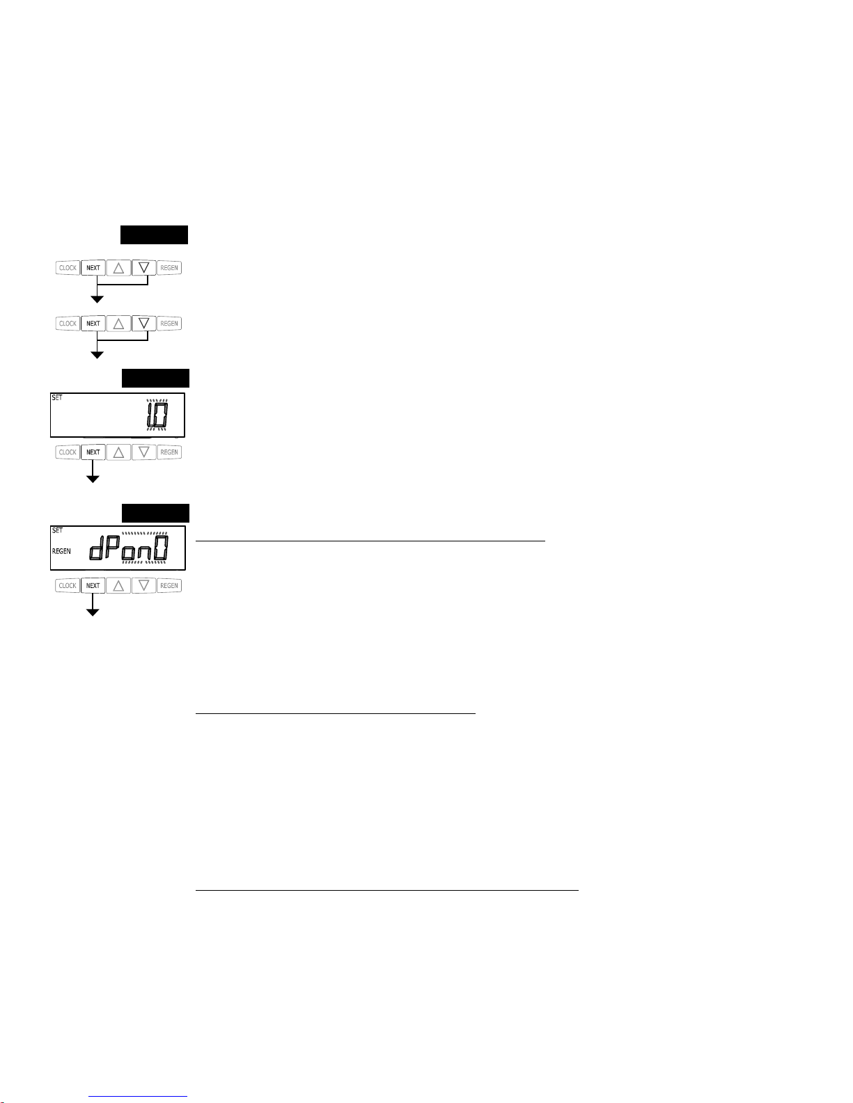
Step 1C – Press NEXT and ▼ simultaneously for 3 seconds and release. Then press NEXT and ▼
simultaneously for 3 seconds and release. If screen in Step 2C does not appear in 5 seconds the lock on
the valve is activated. To unlock press ▼, NEXT, ▲, and SET CLOCK in sequence, then press NEXT and
▼ simultaneously for 3 seconds and release. Then press NEXT and ▼ simultaneously for 3 seconds and
release.
STEP 1C
Step 2C – Use the ▲ or ▼ to select 1.0 for WS1CH or 1.25 for WS1.25CH valve. Press NEXT to go to
Step 3C. Press REGEN to exit OEM Cycle Sequence.
STEP 2C
STEP 3C
Step 3C – Allows selection of one of the following:
• an outside signal to initiate a regeneration;
• the Control Valve to act as an alternator; or
• the Control Valve to have no hard water bypass.
Selecting the use of an outside signal to initiate a regeneration:
Selection only matters if a connection is made to the two pin connector labeled DP SWITCH located on
the printed circuit board. Following is an explanation of the options:
dPon0 - If the dP switch is closed for an accumulative time of 2 minutes a regeneration will occur immediately.
dPdEL - If the dP switch is closed for an accumulative time of 2 minutes a regeneration will occur at the
scheduled regeneration time.
HoLd - If the dP switch is closed a regeneration will be prevented from occurring.
Selecting the Control Valve to act as an alternator:
Note: Also must do one of the following:
• If set up for a softener in Step 9S set Volume Capacity in GALLONS, in Step 10S select Regeneration Time Option “on 0” and in Step 3I select Day Override “oFF”.
• If set up for a fi lter, in Step 8F set Volume Capacity in GALLONS, in Step 9F select Regeneration
Time Option “on 0” and in Step 3I select Day Override “oFF”.
Select ALTA for the control valve that has the two pin connector labeled DRIVE connected to the alternator valve motor.
Select ALTb for the control valve that will not be connected to the alternator valve motor.
Confi guring the Control Valve for No Hard Water Bypass Operation:
Selection requires a connection to a Clack Two Way Motorized Valve or a Clack Motorized Alternator
Valve (MAV) is made to the two pin connector labeled ALTERNATOR DRIVE located on the printed
circuit board. The Clack Two Way Motorized Valve can be connected to the valve outlet in either
direction. The B port of a MAV must be plugged and the valve outlet connected to the A port. The Clack
Two Way Motorized Valve or a Clack Motorized Alternator Valve will be driven closed before the fi rst
regeneration cycle that is not FILL or SOFTENING or FILTERING, and be driven open after the last
regeneration cycle that is not FILL.
Press NEXT to go to Step 4C. Press REGEN to return to previous step.
Page 9
Page 10

RETURN TO NORMAL MODE
STEP 4C – Set Refi ll option using ▼ or ▲ buttons:
• “PoST” to refi ll the brine tank after the fi nal rinse; or
• “PrE” to refi ll the brine tank two hours before the regeneration time set.
If selecting “Filter” in Step 2F, “POST” should always be selected.
Press NEXT to go to Step 5C. Press REGEN to return to previous step.
STEP 5C – Set regenerant downfl ow or upfl ow using ▼ or ▲ buttons:
• “dn” if the regenerant is to fl ow downward through the media; or
• “UP” if the regenerant is to fl ow upward through the media. Step 2C must be set to 1 for a 1” valve.
Prior to selecting a regenerant fl ow direction, verify the correct valve body, main piston, regenerant
piston, and stack are being used, and that the injector or injector plug(s) are in the correct locations. See
Compliance Table in Service Instructions under Injector Cap, Screen, Injector Plug and Injector section
and Figure 6. This screen will not display if the unit is set up as a 1.25”,1.5”,2” or fi lter valve.
If selecting “Filter” in Step 2F, “dn” should always be selected.
Press NEXT to exit OEM Cycle Sequence. Press REGEN to return to previous step.
STEP 4C
STEP 5C
Page 10
Page 11
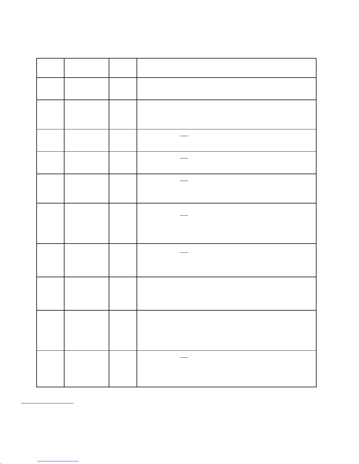
OEM Softener System Setup
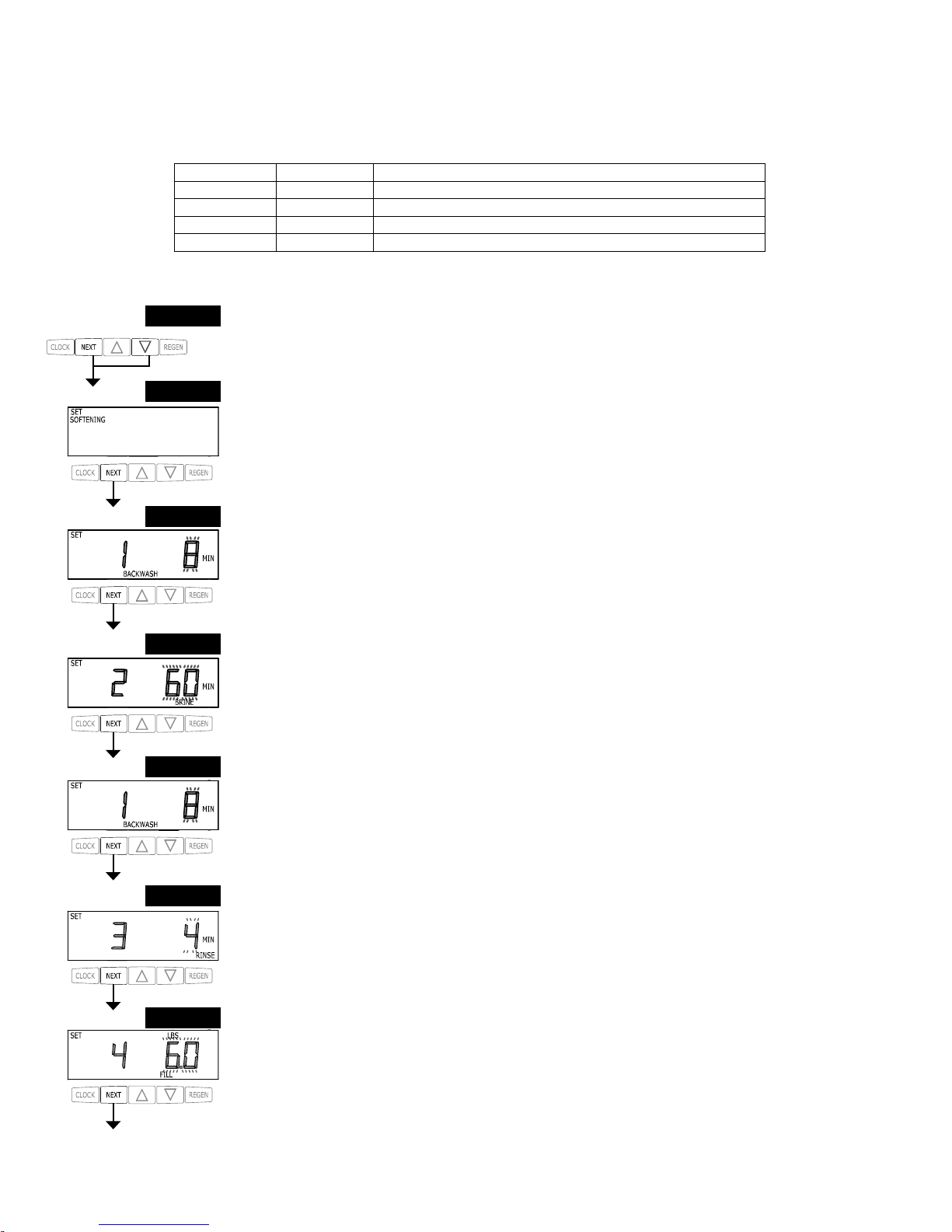
In OEM Softener System Setup the OEM chooses the value for the specifi ed cycles (the order of which is specifi ed by the selections
for Step 4C and Step 5C in OEM Cycle Sequence) and specifi es other operating parameters for the system. If a cycle is present the
value can be set to off. Fill is in pounds of salt and all other cycles are in minutes.
STEP 1S
STEP 3S
STEP 4S
STEP 7S
Step 4C Step 5C Cycle Order
Post dn Backwash, Brine, Backwash, Rinse, Fill
Pre dn Fill, Service, Backwash, Brine, Backwash, Rinse
Post UP Brine, Backwash, Rinse, Fill
Pre UP Fill, Service, Brine, Backwash, Rinse
Step 1S – Press NEXT and ▼ simultaneously for 3 seconds and release. If screen in Step 2S does
not appear in 5 seconds the lock on the valve is activated. To unlock press ▼, NEXT, ▲, and SET
CLOCK in sequence, then press NEXT and ▼ simultaneously for 3 seconds and release.
STEP 2S
Note: If “Pre” is selected in Step 4C and “UP” is selected in Step 5C, the proportional brining display will
appear after the Grains Capacity display (Step 8S).
Step 7S – Select the LBS for the fi fth cycle (which in this example is FILL) using the ▼ or ▲ button.
Press NEXT to go to Step 8S. Press REGEN to return to previous step.
STEP 6S
Step 6S – Select the time for the fourth cycle (which in this example is RINSE) using the ▼ or ▲
button. Press NEXT to go to Step 7S. Press REGEN to return to previous step.
Step 4S – Select the time for the second cycle (which in this example is dn BRINE) using the ▼ or
▲ button. Verify the correct valve body, main piston, regenerant piston, and stack are being used,
and that the injector or injector plug(s) are in the correct locations. See Compliance Table in Service
Instructions under Injector Cap, Screen, Injector Plug and Injector section and Figure 6. Press NEXT
to go to Step 5S. Press REGEN to return to previous step.
NOTE: The display will fl ash between cycle number and time, and brine direction (dn or UP).
Step 3S – Select the time for the fi rst cycle (which in this example is BACKWASH) using the ▼ or ▲
button. Press NEXT to go to Step 4S. Press REGEN to return to previous step.
STEP 5S
Step 5S – Select the time for the third cycle (which in this example is BACKWASH) using the ▼ or
▲ button. Press NEXT to go to Step 6S. Press REGEN to return to previous step.
Step 2S – Choose SOFTENING using the ▼ or ▲ button. Press NEXT to go to Step 3S. Press
REGEN to exit OEM Softener System Setup.
Page 11
Page 12
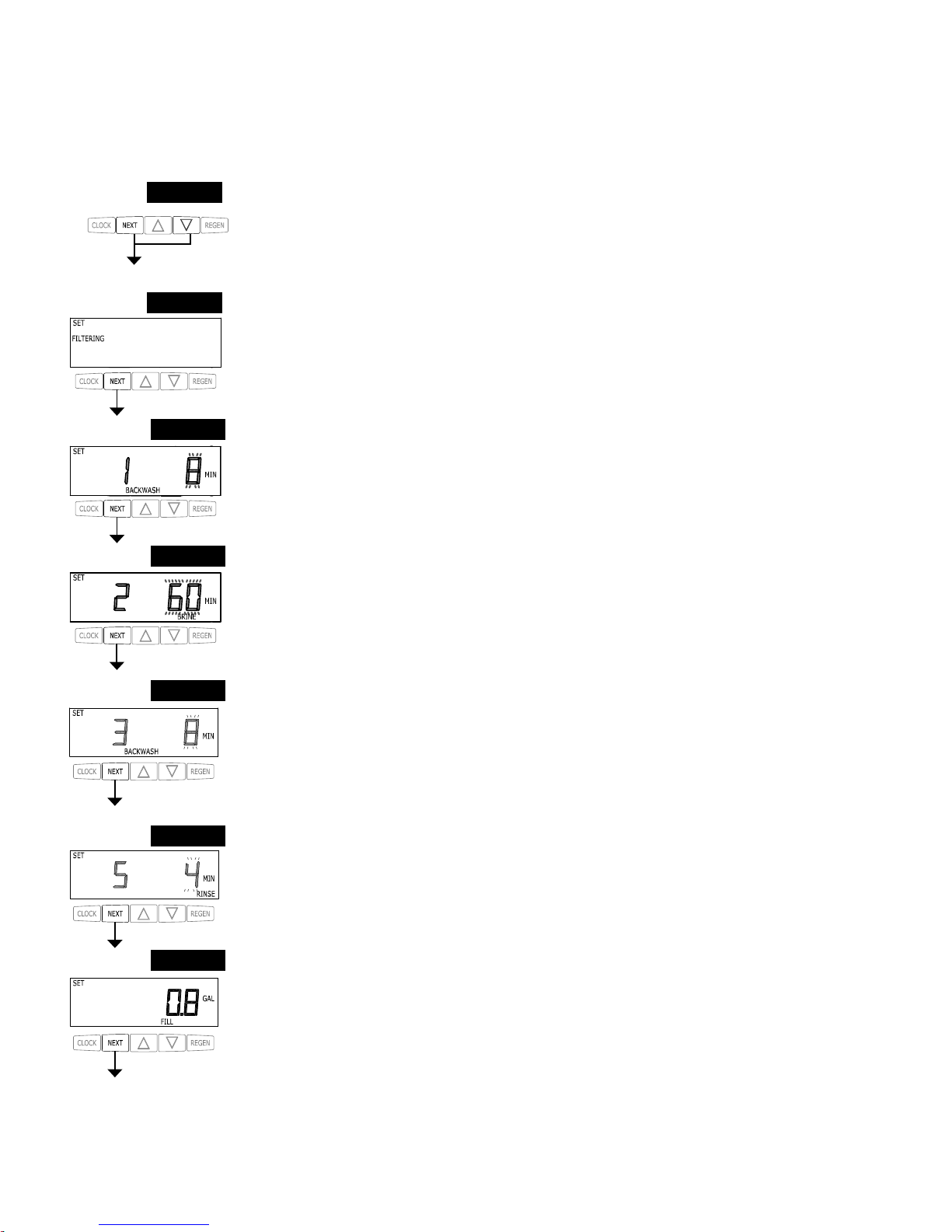
STEP 9S
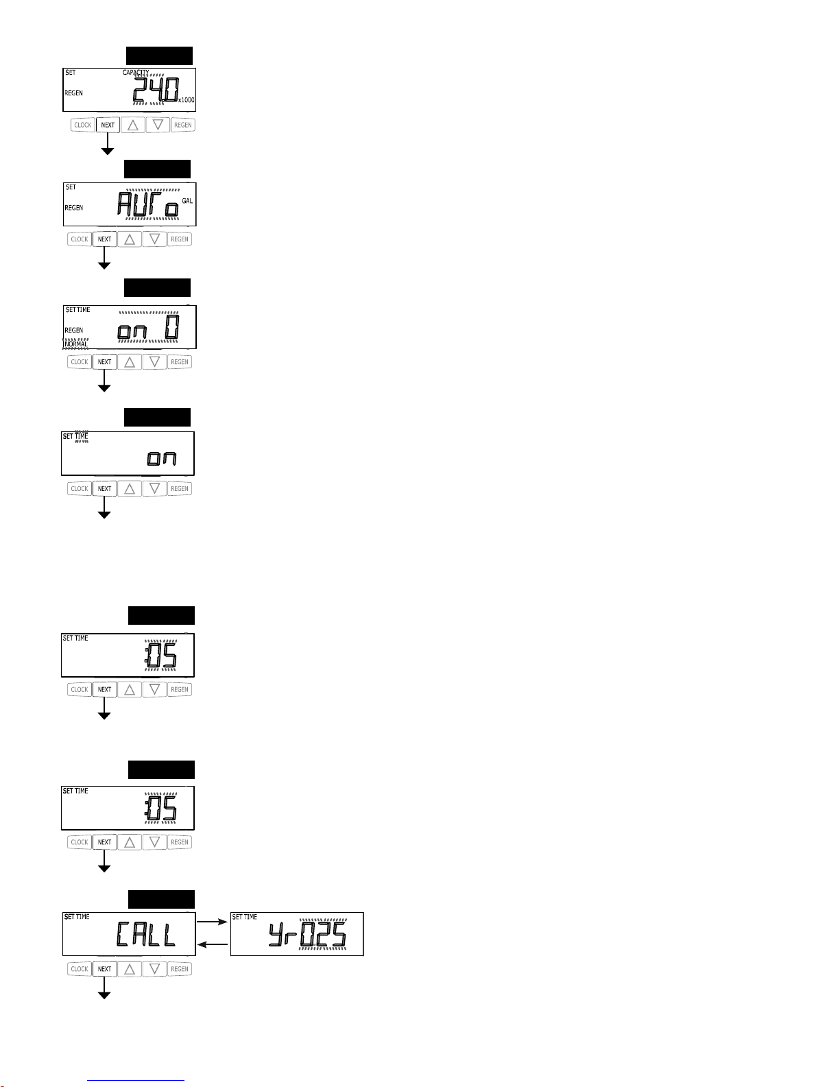
Step 9S – Set Volume Capacity using the ▼ or ▲ button. If value is set to:
• “AUTO” capacity will be automatically calculated and reserve capacity will be automatically estimated;
• “oFF” regeneration will be based solely on the day override set (see Installer Display Settings Step 3I); or
• as a number (allowable range 20 to 250,000) regeneration initiation will be based off the value specifi ed.
If “oFF” or a number is used, hardness display will not be allowed to be set in Installer Display Settings Step 2I.
See Table 8 for more detail. Press NEXT to go to Step 10S. Press REGEN to return to previous step.
STEP 10S
Step 10S – Set Regeneration Time Options using the ▼ or ▲ button. If value is set to:
• “NORMAL” means regeneration will occur at the preset time;
• “on 0” means regeneration will occur immediately when the gallons capacity reaches 0 (zero); or
• “NORMAL + on 0” means regeneration will occur at one of the following:
— the preset time when the gallons capacity falls below the reserve or the specifi ed number of days between
regenerations is reached, whichever comes fi rst; or
— after 10 minutes of no water usage when the gallons capacity reaches 0 (zero). See Table 8 for more detail.
Press NEXT to go to Step 11S. Press REGEN to return to previous step.
Step 11S – Set Relay operation using the ▼ or ▲ button. The choices are:
• Relay Actuation Time: After the start of a regeneration the amount of time that should pass prior to activating the
relay. The start of regeneration is defi ned as the fi rst backwash cycle, Dn brine cycle or UP brine cycle which ever
comes fi rst.
• Set Gal Softening on: Relay activates after a set number of gallons have been used while in service and then
deactivates after a set period of time or after the meter stops registering fl ow, whichever comes fi rst.
• Set Gal Softening Regen on: Relay activates after a set number of gallons have been used while in service
or during regeneration and then deactivates after a set period of time or after the meter stops registering fl ow,
whichever comes fi rst.
• Set Gal HoLd: Relay closes every set number of gallons and releases when the ▲ button is pressed.
• Set Off: If set to Off, Steps 12S and 13S will not be shown.
Press NEXT to go to Step 12S. Press REGEN to return to previous step.
STEP 11S
STEP 12S
Step 12S: Set Relay Actuation Time or Gallons using the ▲ or ▼ buttons. The choices are:
• Relay Actuation Time: After the start of a regeneration the amount of time that should pass prior to activating
the relay. The start of regeneration is defi ned as the fi rst backwash cycle or Dn brine cycle, which ever comes fi rst.
Ranges from 1 minute to 500 minutes.
• Relay Actuation Gallons: Relay activates after a set number of gallons have passed. Ranges from 1 to 100
gallons.
• Relay HoLd: Relay closes every set number of gallons. Ranges from 1,000 to 99,000,000 gallons.
Press NEXT to go to Step 13S. Press REGEN to return to previous step.
STEP 13S
Step 13S: Set Relay Deactivate Time using the ▲ or ▼ buttons.
• If Set Time on is selected in Step 11S the relay will deactivate after the time set has expired. Ranges from 1
second to 500 minutes.
• If Set Gal Softening on or Set Gal Softening Regen on is selected in Step 11S the relay will deactivate after the
time set has expired or after the meter stops registering fl ow, whichever comes fi rst. Ranges from 1 second to 500
minutes.
• Does not display for Gal HoLd selection.
Press NEXT to go to Step 14S. Press REGEN to return to previous step.
Step 14S: Set the Service Call Indicator by using the ▲ or ▼ buttons. Range is
in ¼ of a year increments from 0.25 to 9.75 years. Selecting OFF will disable this
feature.
Press NEXT to exit OEM Softener System Setup. Press REGEN to return to
previous step.
STEP 14S
RETURN TO NORMAL MODE
Step 8S –Set Grains Capacity using the ▼ or ▲ button. The ion exchange capacity is in grains of hardness as
calcium carbonate for the system based on the pounds of salt that will be used. Calculate the pounds of salt using
the fi ll time previously selected. The allowable grains capacity range varies from 5000 to 500,000 grains. Grains
capacity is affected by the fi ll time. The grains capacity for the selected fi ll time should be confi rmed by OEM
testing. The capacity and hardness levels entered are used to automatically calculate reserve capacity when gallon
capacity is set to AUTO. Press NEXT to go to Step 9S. Press REGEN to return to previous step.
STEP 8S
Page 12
Page 13
8
Reserve capacity estimate is based on history of water usage.
Table 8
Softener Setting Options
Gallons
Capacity
Regeneration
Time Option
Day
Override
Result
8
AUTO NORMAL oFF
Reserve capacity automatically estimated.
Regeneration occurs when gallons capacity falls below the reserve
capacity at the next Regen Set Time.
AUTO NORMAL
Any
number
Reserve capacity automatically estimated.
Regeneration occurs at the next Regen Set Time when gallons capacity
falls below the reserve capacity or the specifi ed number of days between
regenerations is reached.
Any
number
NORMAL oFF
Reserve capacity not automatically estimated.
Regeneration occurs at the next Regen Set Time when gallons capacity
reaches 0.
oFF NORMAL
Any
number
Reserve capacity not automatically estimated.
Regeneration occurs at the next Regen Set Time when the specifi ed
number of days between regenerations is reached.
Any
number
NORMAL
Any
number
Reserve capacity not automatically estimated.
Regeneration occurs at the next Regen Set Time when gallons capacity
reaches 0 or the specifi ed number of days between regenerations is
reached.
AUTO On O oFF
Reserve capacity not automatically estimated.
Regeneration occurs immediately when gallons capacity reaches 0.
Time of regeneration will not be allowed to be set because regeneration
will always occur when gallons capacity reaches 0.
Any
number
On O oFF
Reserve capacity not automatically estimated.
Regeneration occurs immediately when gallons capacity reaches 0.
Time of regeneration will not be allowed to be set because regeneration
will always occur on 0.
AUTO NORMAL on 0 oFF
Reserve capacity automatically estimated.
Regeneration occurs when gallons capacity falls below the reserve
capacity at the next Regen Set Time or regeneration occurs immediately
after 10 minutes of no water usage when gallon capacity reaches 0.
AUTO NORMAL on 0
Any
number
Reserve capacity automatically estimated.
Regeneration occurs at the next Regen Set Time when gallons capacity
falls below the reserve capacity or the specifi ed number of days between
regenerations is reached or regeneration occurs immediately after 10
minutes of no water usage when gallon capacity reaches 0.
Any
number
NORMAL on 0
Any
number
Reserve capacity not automatically estimated.
Regeneration occurs at the next Regen Set Time when the specifi ed
number of days between regenerations is reached or regeneration occurs
immediately after 10 minutes of no water usage when gallon capacity
reaches 0.
Page 13
Page 14
STEP 1F
STEP 2F
STEP 3F
STEP 4F
STEP 6F
OEM Filter System Setup
In OEM Filter System Setup the order of the cycles is preset to Backwash, dn Brine, Backwash, Rinse and Fill. Fill is set in gallons
and all other cycles are set in minutes. Each cycle can be set to off. Fill is always Post Fill even if Pre is selected in Step 4C.
Step 6F – Select the time for the fi fth cycle (which in this example is RINSE) using the ▼ or ▲ button.
Press NEXT to go to Step 7F. Press REGEN to return to previous step.
STEP 5F
Step 5F – Select the time for the third cycle using the ▼ or ▲ button. Press NEXT to go to Step 6F.
Press REGEN to return to previous step.
Step 1F – Press NEXT and ▼ simultaneously for 3 seconds and release. If screen in Step 2F does not
appear in 5 seconds the lock on the valve is activated. To unlock press ▼, NEXT, ▲, and SET CLOCK
in sequence, then press NEXT and ▼ simultaneously for 3 seconds and release.
Step 2F – Choose FILTERING using the ▼ or ▲ buttons. Press NEXT to go to Step 3F. Press REGEN
to exit OEM Filter System Setup.
Step 3F – Select the time for the fi rst cycle using the ▼ or ▲ button. Press NEXT to go to Step 4F. Press
REGEN to return to previous step.
Step 4F – Select the time for the second cycle using the ▼ or ▲ button. Press NEXT to go to Step 5F.
Press REGEN to return to previous step.
NOTE: The display will fl ash between cycle number and time, and brine direction (dn or UP).
STEP 7F – Enter “oFF” if regenerant is not used (i.e. backwash only) or enter the refi ll volume (in
gallons) using ▼ or ▲ buttons. Prior to selecting oFF or regenerant volume, verify the correct valve
body, main piston, regenerant piston, and stack are being used, and that the injector or injector plug(s)
are in the correct locations. See Compliance Table in Service Instructions under Injector Cap, Screen,
Injector Plug and Injector section and Figure 6.
Press NEXT to go to Step 8F. Press REGEN to return to previous step.
STEP 7F
Page 14
Page 15
STEP 9F
Step 8F – Set Volume Capacity using the ▼ or ▲ button. If value is set to:
• “oFF” regeneration will be based solely on the day override set (see Installer Display/Settings Step 3I); or
• as a number (allowable range 20 to 250,000) regeneration initiation will be based off the value specifi ed.
See Table 9 for more detail. Press NEXT to go to Step 9F. Press REGEN to return to previous step.
STEP 8F
Step 10F: Set Relay operation using the ▲ or ▼ button. The choices are:
• Set Time on: Relay activates after a set time at the beginning of a regeneration and then deactivates after a set
period of time. The start of regeneration is defi ned as the fi rst backwash cycle or Dn brine cycle, which ever comes
fi rst.
• Set Gal Filtering on: Relay activates after a set number of gallons have been used while in service
and then deactivates after a set period of time or after the meter stops registering fl ow, whichever comes fi rst.
• Set Gal Filtering Regen on: Relay activates after a set number of gallons have been used while in service
or during regeneration and then deactivates after a set period of time or after the meter stops registering fl ow,
whichever comes fi rst.
• Set Gallons HoLd: Relay closes every set number of gallons and releases when the ▲ button is pressed.
• Set Off: If set to Off, Steps 11F and 12F will not be shown.
Press NEXT to go to Step 11F. Press REGEN to return to previous step.
STEP 10F
STEP 11F
Step 11F: Set Relay Actuation Time or Gallons using the ▲ or ▼ buttons. The choices are:
• Relay Actuation Time: After the start of a regeneration the amount of time that should pass prior to activating
the relay. The start of regeneration is defi ned as the fi rst backwash cycle or Dn brine cycle, which ever comes fi rst.
Ranges from 1 minute to 500 minutes.
• Relay Actuation Gallons: Relay activates after a set number of gallons have passed. Ranges from 1 to 100
gallons.
• Relay HoLd: Relay closes every set number of gallons. Ranges from 1,000 to 99,000,000 gallons.
Press NEXT to go to Step 12F. Press REGEN to return to previous step.
STEP 12F
Step 12F: Set Relay Deactivate Time using the ▲ or ▼ buttons.
• If Set Time on is selected in Step 10F the relay will deactivate after the time set has expired. Ranges from 1
second to 500 minutes.
• If Set Gal Filtering on or Set Gal Filtering Regen on is selected in Step 10F the relay will deactivate after the
time set has expired or after the meter stops registering fl ow, whichever comes fi rst. Ranges from 1 second to 500
minutes.
• Does not display for Gallons HoLd selection.
Press NEXT to go to Step 13F. Press REGEN to return to previous step.
Step 9F – Set Regeneration Time Options using the ▼ or ▲ button. If value is set to:
• “NORMAL” means regeneration will occur at the preset time;
• “on 0” means regeneration will occur immediately when the gallons capacity reaches 0 (zero); or
• “NORMAL + on 0” means regeneration will occur at one of the following:
— the preset time when the gallons capacity falls below the reserve or the specifi ed number of days between
regenerations is reached whichever comes fi rst;
or
— after 10 minutes of no water usage when the gallon capacity reaches 0 (zero).
See Table 9 for more detail. Press NEXT to go to Step 10F. Press REGEN to return to previous step.
Step 13F: Set the Service Call Indicator by using the ▲ or ▼ buttons. Range
is in ¼ of a year increments from 0.25 to 9.75 years. Selecting OFF will disable
this feature.
Press NEXT to exit OEM Filter System Setup. Press REGEN to return to
previous step.
STEP 13F
RETURN TO NORMAL MODE
Page 15
Page 16
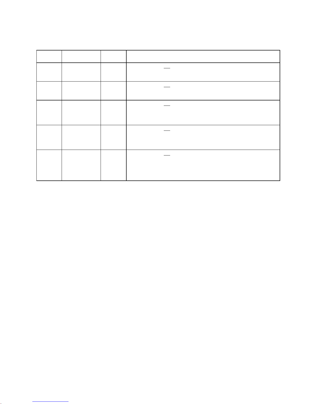
Table 9
Filter Setting Options
Gallons
Capacity
Regeneration
Time Option
Day
Override
Result
oFF NORMAL
Any
number
Reserve capacity not automatically estimated.
Regeneration occurs at the next Regen Set Time when the specifi ed
number of days between regenerations is reached.
Any
number
NORMAL oFF
Reserve capacity not automatically estimated.
Regeneration occurs at the next Regen Set Time when gallons capacity
reaches 0.
Any
number
NORMAL
Any
number
Reserve capacity not automatically estimated.
Regeneration occurs at the next Regen Set Time when gallons capacity
reaches 0 or the specifi ed number of days between regenerations is
reached.
Any
number
On O oFF
Reserve capacity not automatically estimated.
Regeneration occurs immediately when gallons capacity reaches 0.
Time of regeneration will not be allowed to be set because regeneration
will always occur on 0.
Any
number
NORMAL on 0
Any
number
Reserve capacity not automatically estimated.
Regeneration occurs at the next Regen Set Time when the specifi ed
number of days between regenerations is reached or regeneration occurs
immediately after 10 minutes of no water usage when gallon capacity
reaches 0.
Page 16
Page 17
Installer Display Settings
STEP 1I
STEP 2I
STEP 4I
STEP 5I
RETURN TO
NORMAL MODE
STEP 3I
STEP 1I - Press NEXT and ▲ simultaneously for 3 seconds.
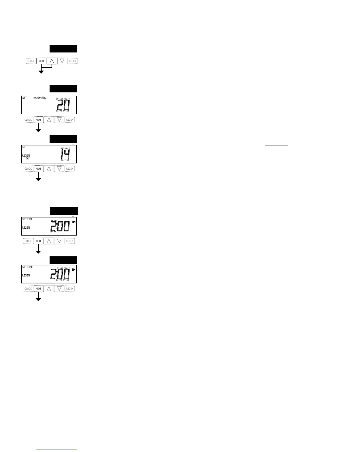
STEP 2I – Hardness: Set the amount of hardness in grains of hardness as calcium carbonate per
gallon using the ▼ or ▲ buttons. The default is 20 with value ranges from 1 to 150 in 1 grain
increments. Note: The grains per gallon can be increased if soluble iron needs to be reduced. This
display will show “–nA–” if “FILTER” is selected in Step 2F or if ‘AUTO’ is not selected in Set
Volume Capacity in OEM Softener System Setup. Press NEXT to go to step 3I. Press REGEN to exit
Installer Display Settings.
STEP 3I – Day Override: When volume capacity is set to “oFF”, sets the number of days between
regenerations. When volume capacity is set to AUTO or to a number, sets the maximum number of
days between regenerations. If value set to “oFF”, regeneration initiation is based solely on volume
used. If value is set as a number (allowable range from 1 to 28) a regeneration initiation will be
called for on that day even if suffi cient volume of water were not used to call for a regeneration. Set
Day Override using ▼ or ▲ buttons:
• number of days between regeneration (1 to 28); or
• “oFF”.
See Table 8 for more detail on softener setup and Table 9 for more detail on fi lter setup. Press NEXT
to go to step 4I. Press REGEN to return to previous step.
STEP 4I – Next Regeneration Time (hour): Set the hour of day for regeneration using ▼ or ▲ but-
tons. AM/PM toggles after 12. The default time is 2:00 AM. This display will show “on 0” if “on 0”
is selected in Set Regeneration Time Option in OEM Softener System Setup or OEM Filter System
Setup. Press NEXT to go to step 5I. Press REGEN to return to previous step.
STEP 5I – Next Regeneration Time (minutes): Set the minutes of day for regeneration using ▼ or
▲ buttons. This display will not be shown if “on 0” is selected in Set Regeneration Time Option
in OEM Softener System Setup or OEM Filter System Setup. Press NEXT to exit Installer Display
Settings. Press REGEN to return to previous step.
To initiate a manual regeneration immediately, press and hold the “REGEN” button for three
seconds. The system will begin to regenerate immediately. The control valve may be stepped through
the various regeneration cycles by pressing the “REGEN” button.
Page 17
Page 18
User Display Settings
General Operation
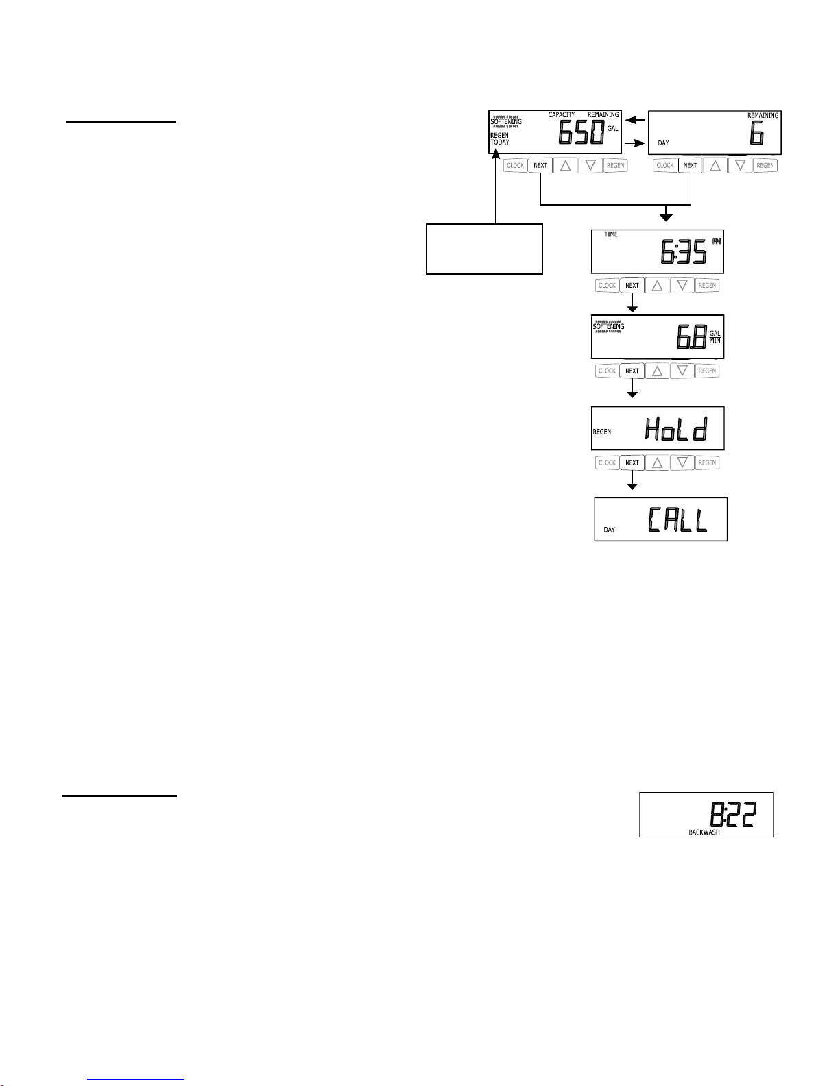
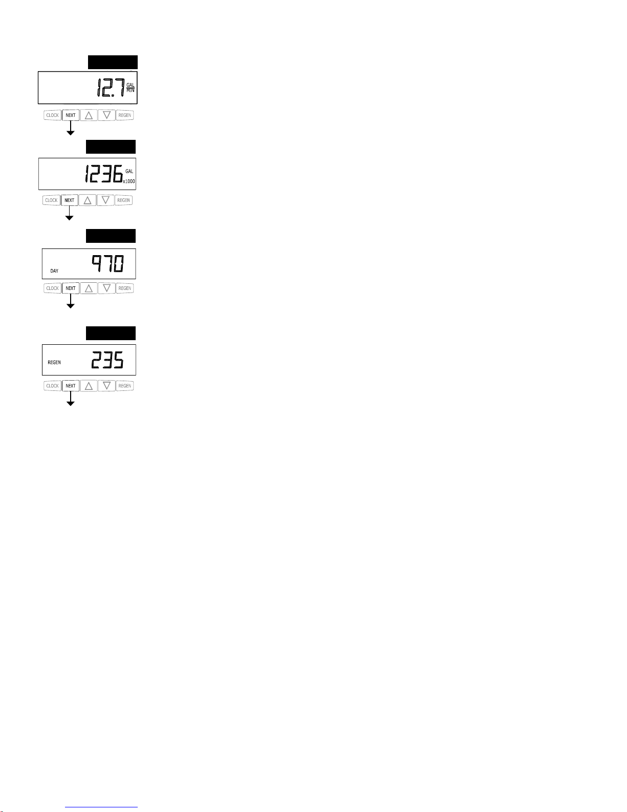
When the system is operating, one of fi ve displays may be shown.
Pressing NEXT will alternate between the displays. One of the
displays is always the current time of day.
The second display is one of the following: days remaining or
volume remaining. Days remaining is the number of days left
before the system goes through a regeneration cycle. Capacity
remaining is the gallons that will be treated before the system
goes through a regeneration cycle. Pressing the ▼ button while
in the Capacity Remaining display will decrease the capacity
remaining in 10 gallon increments and will also increase the
volume used impacting the recorded values in Diagnostics Steps
3D, 4D and 5D and Valve History, Step 4VH.
The third display shows the current treated water fl ow rate
through the system. The fourth display will show either dP or hold
if the dP switch is closed.
The fi fth display indicates the user should call for service. The
fi fth display will not appear if OFF is selected in Step 14S of
OEM Softener System Setup or Step 13F of OEM Filter System
Setup. To clear the Service Call reminder, press the ▲ and ▼
buttons simultaneously while CALL is displayed.
If the system has called for a regeneration that will occur at the
preset time of regeneration, the words REGEN TODAY will
appear on the display.
If a water meter is installed, the word “Softening” or “Filtering”
fl ashes on the display when water is being treated (i.e. water is
fl owing through the system).
or
REGEN TODAY will
Flash if a regeneration
is expected “Tonight.”
Regeneration Mode
Typically a system is set to regenerate at a time of low water usage. An example of a time with
low water usage is when a household is asleep. If there is a demand for water when the system is
regenerating, untreated water will be used.
When the system begins to regenerate, the display will change to include information about the step of the regeneration process and
the time remaining for that step to be completed. The system runs through the steps automatically and will reset itself to provide
treated water when the regeneration has been completed.
Page 18
Page 19
Manual Regeneration
Sometimes there is a need to regenerate the system sooner than when the
system calls for it, usually referred to as manual regeneration. There may
be a period of heavy water usage because of guests or a heavy laundry day.
To initiate a manual regeneration at the preset delayed regeneration time, when the regeneration time option is set to “NORMAL” or
“NORMAL + on 0”, press and release “REGEN”. The words “REGEN TODAY” will fl ash on the display to indicate that the system
will regenerate at the preset delayed regeneration time. If you pressed the “REGEN” button in error, pressing the button again
will cancel the request. Note: If the regeneration time option is set to “on 0” there is no set delayed regeneration time so “REGEN
TODAY” will not activate if “REGEN” button is pressed.
To initiate a manual regeneration immediately, press and hold the “REGEN” button for three seconds. The system will begin to
regenerate immediately. The request cannot be cancelled.
Note: For softeners, if the brine tank does not contain salt, fi ll with salt and wait at least two hours before regenerating.
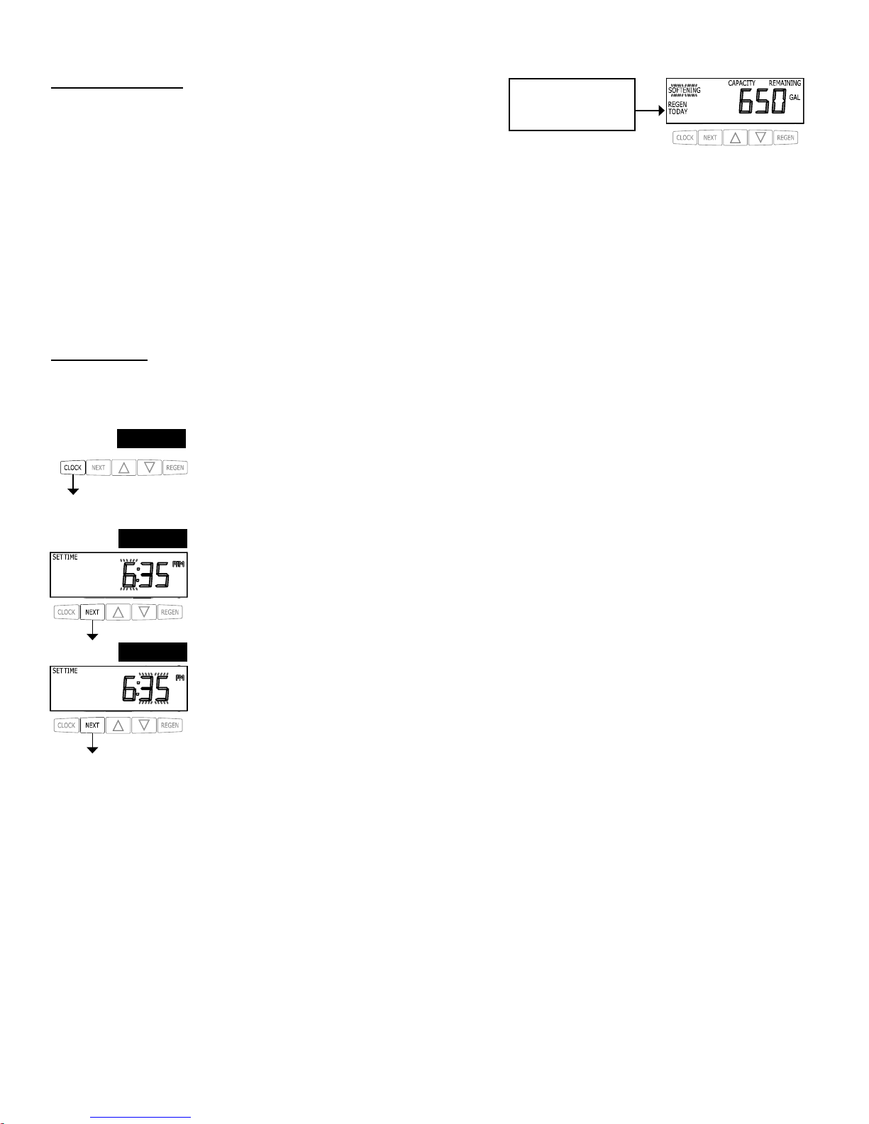
Set Time of Day
The user can also set the time of day. Time of day should only need to be set if the battery has been depleted because of extended
power outages or when daylight saving time begins or ends. If an extended power outage occurs, the time of day will fl ash on and
off which indicates the time of day should be reset. The non rechargeable battery should also be replaced.
STEP 1U
STEP 2U
STEP 3U
RETURN TO NORMAL MODE
STEP 1U – Press SET CLOCK.
STEP 2U - Current Time (hour): Set the hour of the day using ▼ or ▲ buttons. AM/PM toggles after 12.
Press NEXT to go to Step 3U.
STEP 3U - Current Time (minutes): Set the minutes of the day using ▼ or ▲ buttons. Press NEXT to
exit Set Time of Day. Press REGEN to return to previous step.
REGEN TODAY will
Flash if a regeneration is
expected “Tonight.”
Page 19
Page 20
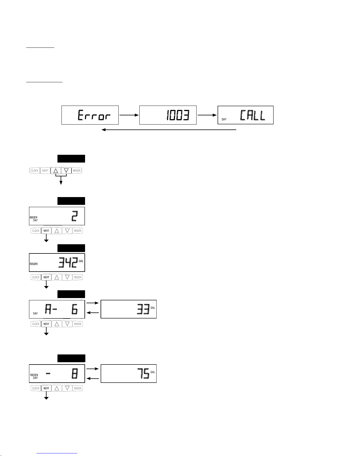
STEP 1D – Press ▲ and ▼ simultaneously for three seconds. If screen in step 2D does not appear in 5
seconds the lock on the valve is activated. To unlock press ▲, NEXT, ▼, and SET CLOCK in sequence, then press ▲ and ▼ simultaneously for 3 seconds.
STEP 2D – Days, since last regeneration: This display shows the days since the last regeneration oc-
curred. Press the NEXT button to go to Step 3D. Press REGEN to exit Diagnostics.
STEP 3D – Volume, since last regeneration: This display shows the volume of water that has been
treated since the last regeneration. This display will equal zero if a water meter is not installed. Press
the NEXT button to go to Step 4D. Press REGEN to return to previous step.
STEP 4D – Volume, reserve capacity used for last 7 days: If the valve is
set up as a softener, a meter is installed and Set Volume Capacity is set
to “Auto,” this display shows 0 day (for today) and fl ashes the reserve
capacity. Pressing the ▲ button will show day 1 (which would be yesterday) and fl ashes the reserve capacity used. Pressing the ▲ button again will show day 2 (the day before
yesterday) and the reserve capacity. Keep pressing the ▲ button to show the capacity for days 3, 4, 5
and 6. The ▼ button can be pressed to move backwards in the day series. Press the NEXT button at
any time to go to Step 5D. Press REGEN to return to previous step.
STEP 5D - Volume, 63-day usage history: This display shows day 1 (for
yesterday) and fl ashes the volume of water treated yesterday. Pressing
the ▲ button will show day 2 (which would be the day before yesterday)
and fl ashes the volume of water treated on that day. Continue to press the
▲ button to show the maximum volume of water treated for the last 63 days. If a regeneration occured
on the day the word “REGEN” will also be displayed. This display will show dashes if a water meter is
not installed. Press the NEXT button at any time to go to Step 6D. Press REGEN to return to previous
step.
STEP 1D
STEP 2D
STEP 3D
STEP 4D
STEP 5D
Diagnostics
Power Loss
If the power goes out the system will keep time until the battery is depleted. If an extended power outage
occurs, the time of day will fl ash on and off which indicates the time of day should be reset and the battery
replaced. The system will remember the rest.
Error Message
If the word “ERROR,” a number and the word “CALL” are alternately fl ashing on the display contact the
OEM for help. A number indicates that the valve was not able to function properly.
RETURN TO NORMAL MODE
Page 20
Page 21
When desired, all information in Diagnostics may be reset to zero when the valve is installed in a new location. To reset
to zero, press NEXT and ▼ buttons simultaneously to go to the Service/OEM 1 screen, and release. Press ▲ and ▼
simultaneously to reset diagnostic values to zero. Screen will return to User Display.
STEP 6D
STEP 6D – Flow rate, maximum last seven days: The maximum fl ow rate in gallons per minute that
occurred in the last seven days will be displayed. This display will equal zero if a water meter is not
installed. Press the NEXT button to exit Diagnostics. Press REGEN to return to previous step.
STEP 7D – Gallons, total used since start-up: This display shows the total gallons treated since startup.
This display will equal zero if a water meter is not installed. Press the NEXT button to go to Step 8D.
Press REGEN to return to previous step.
STEP 7D
STEP 8D – Days, total since start-up: This display shows the total days since startup. Press the NEXT
button to go to Step 9D. Press REGEN to return to previous step.
STEP 8D
STEP 9D – Regenerations, total number since start-up: This display shows the total number of
regenerations that have occurred since startup. Press the NEXT button to exit Diagnostics. Press
REGEN to return to previous step.
STEP 9D
RETURN TO NORMAL MODE
Page 21
Page 22
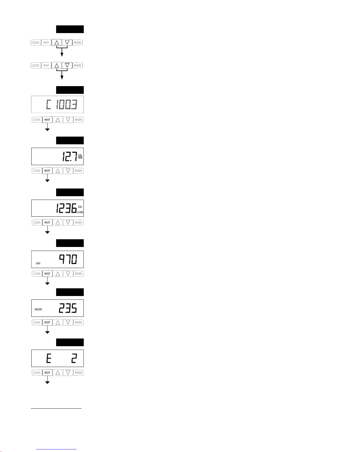
STEP 1VH – Press ▲ and ▼ simultaneously for three seconds and release. Then press ▲ and ▼
simultaneously and release. If screen in step 2VH does not appear in 5 seconds the lock on the valve
is activated. To unlock press ▼, NEXT, ▲, and SET CLOCK in sequence, then press ▲ and ▼
simultaneously for 3 seconds and release. Then press ▲ and ▼ simultaneously and release.
STEP 1VH
RETURN TO NORMAL MODE
Valve History
STEP 2VH – Software Version: This display shows the software version of the valve. Press the NEXT
button to go to Step 3VH. Press REGEN to exit Valve History.
STEP 3VH9 – Flow rate, maximum since startup: This display shows the maximum fl ow rate in
gallons per minute that has occurred since startup. This display will equal zero if a water meter is not
installed. Press the NEXT button to go to Step 4VH. Press REGEN to return to previous step.
STEP 4VH – Gallons, total used since start-up: This display shows the total gallons treated since
startup. This display will equal zero if a water meter is not installed. Press the NEXT button to go to
Step 5VH. Press REGEN to return to previous step.
STEP 5VH – Days, total since start-up: This display shows the total days since startup. Press the
NEXT button to go to Step 6VH. Press REGEN to return to previous step.
STEP 6VH – Regenerations, total number since start-up: This display shows the total number of
regenerations that have occurred since startup. Press the NEXT button to go to Step 7VH. Press
REGEN to return to previous step.
STEP 7VH – Error, number of occurrences since start-up: This display shows E and the total number
of errors that have occurred since startup. Press the NEXT button to exit Valve History. Press REGEN
to return to previous step.
STEP 2VH
STEP 3VH
STEP 4VH
STEP 5VH
STEP 6VH
STEP 7VH
9
Values in steps 2VH through 7VH cannot be reset.
Page 22
Page 23

Installation
Refill Flow Control Assembly or Refill Port Plug
Control valves that are setup for backwash only come equipped with a refill port plug. The refill port plug has no regenerant line
connection.
Control valves that use a regenerant come equipped with a 3/8” refill flow control assembly. To switch to the ½” refill flow control
assembly, remove the refill flow control and retainer (from the 3/8” refill elbow) by twisting and pulling out. Insert the refill flow
control and retainer into the ½” refill elbow.
To complete the regenerant line connection, orientate the outlet in the desired direction and push the plastic insert into the polytube.
Push the polytube into the nut. Do not use pipe dope or other sealants on threads. The threads for the compression nut do not need
Teflon tape. Tighten the nut securely to create a pressure tight connection. A pliers or crescent wrench may be used to tighten or
unscrew the nut. The nut, gripper and retainer sleeve is a 3 piece assembly that can come apart if removed from the elbow body. Parts
must be reassembled exactly as shown in refill flow control assembly drawing to function properly. If the nut is completely removed
from the body, slip the nut, plastic gripper and retainer sleeve on to the tube then tighten on to the fitting.
Drain Line Flow Control and Fitting Assembly
To determine which drain line flow control to use, obtain media bed expansion tables from the media manufacturer, choose a water
temperature and look up the desired backwash rate per square foot of bed area. Then calculate the backwash rate using the desired tank
diameter. Using Table 7, choose the drain line flow control that has the backwash flow rate closest to the calculated backwash rate. If a
manufacturer chooses to use an external drain line flow control, use an elbow fitting that does not contain a hole.
If the drain line is a 5/8” flexible polytube, slide the nut onto the polytube, then place the polytube insert into the end of the polytube
and tighten the nut on to the ¾” drain line fitting. The nut is only designed for use with flexible polytube. Use other nuts if attaching
different materials.
To access the drain line flow control remove the locking clip by pulling it straight out. Pull fitting out and replace the locking clip so
that it is not misplaced. The drain line fitting is pressed in and has an o-ring seal.
In the ¾” elbow, the white flow control retainer is pressed in and has an o-ring seal. The retainer can be removed by rotating and
pulling. The flow control can be removed by prying upward with a small blade flat screwdriver in one of the slots on the side. The
drain line flow control and retainer can be chemically cleaned in dilute sodium bisulfite or vinegar, or replaced. Do not use a wire
brush to clean the flow control or the washer. The washers are identified with three numbers, which correspond to the flow rate. When
reinstalling make sure the identifying number and the rounded inside diameter on the washer is visible when seated in the retainer. The
white flow control washer retainer can also be removed and cleaned. Push the retainer in firmly when reinstalling.
In the 1” straight fitting, the retainer is the fitting. Unscrew the nut to access the flow control. The drain line flow control and the
fitting can be chemically cleaned or replaced. Do not use a wire brush to clean the flow control or the fitting.
Do not use Vaseline, oils, or other unacceptable lubricants on o-rings. A silicone lubricant may be used on the black o-ring. Use a
pliers or crescent wrench to tighten or unscrew the nut. Do not use a pipe wrench to tighten or loosen nut. Do not use pipe dope or
other sealants on threads. Use Teflon tape on the threads of the drain line control fitting when installing ¾” NPT or 1” straight fitting.
Page 23
Page 24

Installation Fitting Assemblies
The installation fittings connect to the control valve or the bypass valve using nuts that only require hand tightening. Hand tighten nut
connections between control valve and installation fittings, control valve and bypass valve, and bypass valve and installation fittings
allow for easy serviceability. Do not use a pipe wrench to tighten nuts on installation fittings. Hand tighten only.
The split ring retainer design holds the nut on and allows load to be spread over the entire nut surface area, reducing the chance for
leakage. The split ring design, incorporated into the installation fittings allows approximately 2 degrees off axis alignment to the
plumbing system. The installation fittings are designed to accommodate minor plumbing misalignments but are not designed to
support the weight of a system or the plumbing.
When assembling the installation fitting package, connect the fitting to the plumbing system first and then attach the nut, split ring and
o-ring. Heat from soldering or solvent cements may damage the nut, split ring or o-ring. Solder joints should be cool and solvent
cements should be set before installing the nut, split ring and o-ring. Avoid getting primer and solvent cement on any part of the
o-rings, split rings, bypass valve or control valve. Solvent cements and primers should be used in accordance with the manufacturer’s
instructions.
Slip the nut onto the fitting first, then the split ring second and the o-ring last. Hand tighten the nut. If the fitting is leaking tightening
the nut will not stop the leak. Remove the nut, remove the fitting, and check for damage or misalignment of the o-ring.
Do not use pipe dope or other sealant on threads. Use teflon tape on threaded inlet, outlet and drain fittings. Teflon tape is not
necessary on the nut connection or caps because of o-ring seals.
Do not use Vaseline, oils, or other unacceptable lubricants on o-rings. A silicone lubricant may be used on black o-rings.
Bypass Valve
The bypass valve easily connects to the control valve body using nuts that only require hand tightening. Hand tighten nut
connections between control valve and fittings, control valve and bypass valve, and bypass valve and installation fittings allow for
easy serviceability. The split ring retainer design holds the nut on and allows load to be spread over the entire nut surface area,
reducing the chance for leakage. The split ring design incorporated into the bypass allows approximately 2 degrees off axis alignment
to the plumbing system. The bypass is designed to accommodate minor plumbing misalignments but is not designed to support the
weight of a system or the plumbing.
Avoid getting primer and solvent cements on any part of the o-rings or split rings, bypass valve or control valve. Do not use pipe dope
or other sealant on threads. Teflon tape is not necessary on the caps because of o-ring seals.
Do not use Vaseline, oils, or other unacceptable lubricants on o-rings. A silicone lubricant may be used on black o-rings.
Mixing Valve
The mixing valve is an option on the control valve. If the control valve is ordered with a mixing valve it will be installed in the control
valve assembly process.
To adjust the blended water, close the mixing valve. Open a water faucet to the desired flow rate. Open the mixing valve until the
desired hardness is reached. Close the faucet.
Note: The use of the mixing valve requires modification to the valve body. These modifications should not be done in the field.
Page 24
Page 25

Service Instructions
Drive Assembly
Remove the valve cover to access the drive assembly.
Disconnect the power source plug (black wire) from the PC board prior to disconnecting the motor or water meter plugs from the PC
board. The power source plug connects to the four-pin jack. The motor plug connects to the two-pin jack on the left-hand side of the
PC board. The water meter plug (gray wire) connects to the three-pin jack on the far right-hand side of the PC board.
The PC board can be removed separately from the drive bracket but it is not recommended. Do not attempt to remove the display
panel from the PC board. Handle the board by the edges. To remove the PC board from the drive bracket, unplug the power, water
meter and motor plugs from the PC board. Lift the middle latch along the top of the drive bracket while pulling outward on the top of
the PC board. The drive bracket has two plastic pins that fit into the holes on the lower edge of the PC board. Once the PC board is
tilted about 45° from the drive bracket it can be lifted off of these pins. To reinstall the PC board, position the lower edge of the PC
board so that the holes in the PC board line up with the plastic pins. Push the top of the PC board towards the valve until it snaps under
the middle latch, weave the power and water meter wires into the holders and reconnect the motor, water meter and power plugs.
The drive bracket must be removed to access the drive cap assembly and pistons or the drive gear cover. It is not necessary to remove
the PC board from the drive bracket to remove the drive bracket. To remove the drive bracket start by removing the plugs for the
power source and the water meter. Unweave the wires from the side holders. Two tabs on the top of the drive back plate hold the drive
bracket in place. Simultaneously lift the two tabs and gently ease the top of the drive bracket forward. The lower edge of the drive
bracket has two notches that rest on the drive back plate. Lift up and outward on the drive bracket to disengage the notches.
To reassemble, seat the bottom of the drive bracket so the notches are engaged at the bottom of the drive back plate. Push the top of
the drive bracket toward the two latches. The drive bracket may have to be lifted slightly to let the threaded piston rod pass through the
hole in the drive bracket. Maintain a slight engaging force on top of the drive bracket while deflecting the bracket slightly to the left
by pressing on the side of the upper right corner. This helps the drive gears mesh with the drive cap assembly. The drive bracket is
properly seated when it snaps under the latches on the drive back plate. If resistance is felt before latching, then notches are not fully
engaged, the piston rod is not in hole, the wires are jammed between the drive bracket and drive back plate, or the gear is not engaging
the drive cap assembly.
To inspect the drive gears, the drive gear cover needs to be removed. Before trying to remove the gear cover, the drive bracket must be
removed from the drive back plate. (Refer to the instructions above regarding removing the drive bracket from the drive back plate.
The drive gear cover can be removed from the drive bracket without removing the motor or the PC board.) The drive gear cover is
held in place on the drive bracket by three clips. The largest of the three clips is always orientated to the bottom of the drive bracket.
With the PC board facing up, push in and down on the large clip on the drive gear cover. Handle the cover and the gears carefully so
that the gears do not fall off the pegs in the cover.
Replace broken or damaged drive gears. Do not lubricate any of the gears. Avoid getting any foreign matter on the reflective coating
because dirt or oils may interfere with pulse counting.
The drive gear cover only fits on one way, with the large clip orientated towards the bottom. If all three clips are outside of the gear
shroud on the drive bracket the drive gear cover slips easily into place.
The drive bracket does not need to be removed from the drive plate if the motor needs to be removed. To remove the motor,
disconnect the power and motor plugs from the jacks on the PC board. Move the spring clip loop to the right and hold. Rotate the
motor at least a ¼ turn in either direction so the wires are vertical (up & down) before gently pulling on the wire connectors to
remove the motor. Pulling directly on the wires without rotating the motor may break the wires off the motor.
Page 25
Page 26

Figure 5
Replace the motor if necessary. Do not lubricate the motor or the gears. To reinstall the motor, move the spring clip loop to the right
and hold. Gently turn the motor while inserting so that the gear on the motor meshes with the gears under the drive gear cover. Release
the spring clip loop and continue to rotate the motor until the wires are horizontal and the motor housing engages the small plastic
bulge inside the drive bracket motor retainer. Reconnect the motor plug to the two-pronged jack on the lower left side of the PC board.
If the motor will not easily engage with the drive gears when reinstalling, lift and slightly rotate the motor before reinserting.
Reconnect the power plug.
Replace the valve cover. After completing any valve maintenance, press and hold NEXT and REGEN buttons for 3 seconds or unplug
power source jack (black wire) and plug back in. This resets the electronics and establishes the service piston position. The display
should flash all wording, then flash the software version and then reset the valve to the service position.
Drive Cap Assembly, Main Piston and Regenerant Piston
The drive assembly must be removed to access the drive cap assembly. The drive cap assembly must be removed to access the
piston(s). The drive cap assembly is threaded into the control valve body and seals with an o-ring. To remove the drive cap assembly
use the special plastic wrench or insert a ¼” to ½” flat blade screwdriver into one of the slots around the top 2” of the drive cap
assembly so it engages the notches molded into the drive back plate around the top 2” of the piston cavity. See Figure 5. The notches
are visible through the holes. Lever the screwdriver so the drive cap assembly turns counter clockwise. Once loosened unscrew the
drive cap assembly by hand and pull straight out.
The drive cap assembly contains the drive cap, the main drive gear, drive cap spline, piston rod and various other parts that should not
be dissembled in the field. The only replaceable part on the drive cap assembly is the o-ring. Attached to the drive cap assembly is the
main piston (downflow or upflow) and if a regenerant is used, a regenerant piston.
Page 26
Page 27

The regenerant piston (the small diameter one behind the main piston) is removed from the main piston by pressing sideways and
unsnapping it from its latch. Chemically clean in dilute sodium bisulfite or vinegar, or replace the regenerant piston if needed. To
remove the main downflow or upflow piston fully extend the piston rod and then unsnap the main piston from its latch by pressing
on the side with the number. Chemically clean in dilute sodium bisulfite or vinegar, or replace the main piston.
Reattach the main piston to the drive cap assembly. Reattach the regenerant piston (if needed) to the main piston. Do not lubricate the
piston rod, main piston or regenerant piston. Lubricant will adversely affect the clear lip seals. Reinsert the drive cap assembly and
piston into the spacer stack assembly and hand tighten the drive cap assembly. Continue to tighten the drive cap assembly using a
screwdriver as a ratchet until the black o-ring on the spacer stack assembly is no longer visible through the drain port. Excessive force
can break the notches molded into the drive back plate. Make certain that the main drive gear still turns freely. The exact position of
the piston is not important as long as the main drive gear turns freely.
Reattach the drive assembly to the control valve and connect all plugs. After completing any valve maintenance, press and hold
NEXT and REGEN buttons for 3 seconds or unplug power source jack (black wire) and plug back in. This resets the electronics
and establishes the service piston position. The display should flash all wording, then flash the software version and then reset the
valve to the service position.
Note: Refer to Figure 6 to identify main piston.
Spacer Stack Assembly
(Refer to Figure 6 for WS1CH & WS1.25CH spacer stack identification.)
To access the spacer stack assembly remove the drive assembly, drive cap assembly and piston. The spacer stack assembly can be
removed easily without tools by using thumb and forefinger. Inspect the black o-rings and clear lip seals for wear or damage. Replace
the entire stack if necessary. Do not disassemble the WS1CH or WS1.25CH stack.
The spacer stack assembly may be chemically cleaned (dilute sodium bisulfite or vinegar) or wiped with a soft cloth.
The spacer stack assembly can be pushed in to the control valve body bore by hand. Since the spacer stack assembly can be
compressed it is easier to use a blunt object (5/8” to 1-1/8” in diameter) to push the center of the assembly into the control valve body.
The assembly is properly seated when at least four threads are exposed (approximately 5/8”). Do not force the spacer stack assembly
in. The control valve body bore interior can be lubricated with silicone to allow for easy insertion of the entire stack. Do not use
silicone or any other type of lubricant on the clear lip seals or the piston.
Reattach the drive cap assembly and piston(s) and the drive assembly.
After completing any valve maintenance, press and hold NEXT and REGEN buttons for 3 seconds or unplug power source jack (black
wire) and plug back in. This resets the electronics and establishes the service piston position. The display should flash all wording,
then flash the software version and then reset the valve to the service position.
Injector Cap, Screen, Injector Plug and Injector
Unscrew the injector cap and lift off. Loosen cap with special plastic wrench or pliers if necessary. Attached to the injector cap is a
screen. Remove the screen and clean if fouled.
The plug and/or injector can be pried out with a small screwdriver. The plug can be wiped clean. If the plug leaks replace the entire
plug. The injector consists of a throat and a nozzle. Chemically clean the injector with vinegar or sodium bisulfite. The holes can be
blown out with air. Both pieces have small diameter holes that control the flow rates of water to insure that the proper concentration
of regenerant is used. Sharp objects, which can score the plastic, should not be used to clean the injector. Scoring the injector or
increasing the diameter of the hole could change the operating parameters of the injector.
Page 27
Page 28

Compliance Table
Application Injector and/or Plug(s) Main Piston
Regenerant
Piston
Stack Body
WS1CH Downfl ow Softener
or Regenerating Filter
Injector in “DN” hole, Plug
in “UP” hole
V3011 V3174 V3005
V3001 or
V3001-02 (Mixing)
WS1CH Backwash Only
Filter
Plug in “DN” and “UP”
holes, Install Refi ll Port Plug
V3011 None V3005
V3001 or
V3001-02 (Mixing)
WS1CH Upfl ow Softener
Injector in “UP” hole, Plug in
unlabeled hole
V3011-01 V3174 V3005
V3001UP or
V3001-02UP (Mixing)
WS1.25CH Downfl ow
Softener or Regenerating
Filter (1.32" Distributor)
Injector in “DN” hole, Plug
in “UP” hole
V3407 V3174 V3430
V3020 or
V3020-01 (Mixing)
WS1.25CH Backwash Only
Filter (1.32" Distributor)
Plug in “DN” and “UP”
holes, Install Refi ll Port Plug
V3407 None V3430
V3020 or
V3020-01 (Mixing)
WS1.25CH Downfl ow
Softener or Regenerating
Filter (32mm Distributor)
Injector in “DN” hole, Plug
in “UP” hole
V3407 V3174 V3430
V3020-02 or
V3020-03 (Mixing)
WS1.25CH Backwash Only
Filter (32mm Distributor)
Plug in “DN” and “UP”
holes, Install Refi ll Port Plug
V3407 None V3430
V3020-02 or
V3020-03 (Mixing)
Two holes are labeled DN and UP. Check for compliance. See Table.
Refill Flow Control Assembly or Refill Port Plug
To clean or replace the refill flow control, pull out the elbow-locking clip and then pull straight up on the elbow. Replace the elbow
locking clip in the slot so that it is not misplaced. Twist to remove the white flow control retainer. The flow control can be removed by
prying upward through the side slots of the retainer with a small flat blade screwdriver.
Chemically clean the flow control or the white flow control retainer using dilute sodium bisulfite or vinegar. Do not use a wire brush.
If necessary, replace the flow control, o-ring on the flow control retainer, or the o-ring on the elbow.
Reseat the flow control so the rounded end is visible in the flow control. Reseat the white flow control retainer by pushing the retainer
into the elbow until the o-ring seats. Remove locking clip, push down on elbow to reseat and insert locking clip.
Do not use Vaseline, oils, or other unacceptable lubricants on o-rings. A silicone lubricant may be used on the o-ring on the elbow or
the white retainer.
Water Meter or Meter Plug
The water meter assembly is connected to the PC board by a wire. If the entire water meter assembly is to be replaced, remove the
control valve cover and disconnect the power source and water meter plugs from the PC board. Unlatch the drive assembly and lean it
forward. Unthread the water meter wire from the side of the drive assembly and through the drive back plate. To reinstall, rethread the
water meter wire through the drive back plate and the side of the drive assembly. Reattach the drive assembly and the water meter and
power plugs.
THIS WATER METER SHOULD NOT BE USED AS THE PRIMARY MONITORING DEVICE FOR CRITICAL HEALTH
EFFECT APPLICATIONS.
If no water meter wire is visible, then a plug is installed, not a water meter.
The water meter wire does not need to be removed from the PC board if the water meter is only being inspected and cleaned. To
remove the water meter assembly, unscrew the meter cap on the left side of the control valve. Pliers may be used to unscrew the
nut if necessary.
With the nut removed, a slot at the top of the water meter is visible. Twist a flat blade screwdriver in the slot between the control
valve body and the meter. When the meter is part way out it is easy to remove the water meter from the housing. Once the water
meter is removed from the control valve body, gently pull forward on the turbine to remove it from the shaft.
Page 28
Page 29

Do not use a wire brush to clean the turbine. Wipe with a clean cloth or chemically clean in dilute sodium bisulfite or vinegar. The
turbine can be immersed in the chemical. Do not immerse electronics. If the turbine is scored or damaged or the bearings on the
turbine are worn, replace the turbine.
Do not lubricate the turbine shaft. The turbine shaft bearings are prelubricated. Do not use Vaseline, oils, or other unacceptable
lubricants on the o-ring. A silicone lubricant may be used on the black o-ring.
Snap the turbine on the shaft and reinsert the water meter into the side slot. Hand tighten the nut. Do not use a pipe wrench to tighten
nut.
Mixing Valve
To clean or replace the mixing valve, unthread the mixing valve from the valve body. Chemically clean the mixing valve with a dilute
sodium bisulfite or vinegar solution. Do not use Vaseline, oils, or other unacceptable lubricants on o-rings. A silicone lubricant may be
used on the o-ring. Before replacing the mixing valve in the valve body turn the knob clockwise so that the mixing valve is in the open
position. Failure to do this may cause damage to the mixing valve when it is screwed in to the valve body.
To adjust the blended water, close the mixing valve. Open a water faucet to the desired flow rate. Open the mixing valve until the
desired hardness is reached. Close the faucet.
Bypass Valve
The working parts of the bypass valve are the rotor assemblies that are contained under the bypass valve caps. Before working on
the rotors, make sure the system is depressurized. Turn the red arrow shaped handles towards the center of the bypass valve and back
several times to ensure rotor is turning freely.
The nuts and caps are designed to be unscrewed or tightened by hand. If necessary a pliers can be used to unscrew the nut or cap. Do
not use a pipe wrench to tighten or loosen nuts or caps. Do not place screwdriver in slots on caps and/or tap with a hammer.
To access the rotor, unscrew the cap and lift the cap, rotor and handle out as one unit. Twisting the unit as you pull it out will help to
remove it more easily. There are three o-rings: one under the rotor cap, one on the rotor stem and the rotor seal. Replace worn o-rings.
Clean rotor. Reinstall rotor.
When reinstalling the red arrow handles be sure that:
1. The handle pointers are lined up with the control valve body arrows, and the rotor seal o-ring and retainer on both rotors
face to the right when being viewed from the front of the control valve; or
2. Arrows point toward each other in the bypass position.
Since the handles can be pulled off, they could be accidentally reinstalled 180° from their correct orientation. To install the red arrow
handles correctly, keep the handles pointed in the same direction as the arrows engraved on the control valve body while tightening the
bypass valve caps.
After completing any valve maintenance, press and hold NEXT and REGEN buttons for 3 seconds or unplug power source jack (black
wire) and plug back in. This resets the electronics and establishes the service piston position. The display should flash all wording,
then flash the software version and then reset the valve to the service position.
Page 29
Page 30

Page 30
Drawings and
Part Numbers
Page 31

WS1CH & WS1.25CH Front Cover and Drive Assembly
Drawing No. Order No. Description Quantity
1 V3435-01 WS1CH Front Cover Assembly 1
2 V3107-01 WS1 Motor 1
3 V3106-01 WS1 Drive Bracket & Spring Clip 1
4 V3558CH WS1/1.25/1.5/2L CH PC Board 1
5V3110 WS1 Drive Gear 12x36 3
6 V3109 WS1 Drive Gear Cover 1
Not Shown
V3186 WS1 AC ADAP TER 110V-12V
1
V3186EU W S1 AC ADAP TER 220-24 0V-1 2V EU
V3186UK WS 1 AC ADAPT ER 220-2 40V-1 2V UK
V3186-01 WS1 AC ADAP TER CORD ONLY
Idec Model and Description
Relay Socket SH3B-05C 3 pole fi nger safe rail mount socket
Relay RH2LB-U-AC12V 12vac, DPDT magnetic latching relay
Relay Specifi cations: To insure proper fi t and correct operation the following relay and relay socket
manufactured by Idec or the exact equivalent should be used.
The relay supplies 2 sets of dry contacts for user applications. The wiring of these
contacts is application specifi c.
Wiring For Correct On/Off Operation
PC Board Relay Terminal Block Relay Socket
SET #13
COM #12 and #14
RES #9
Battery replacement is
3 volt lithium coin cell
type 2032.
Correct
Battery
Orientation
When replacing the battery, align
positives and push down to fully seat.
2
3
5
6
PC Board Relay
Terminal Block
4
1
Page 31
Page 32

WS1CH Drive Cap Assembly, Downfl ow Piston, Upfl ow Piston, Regenerant Piston and Spacer Stack Assembly
Drawing No. Order No. Description Quantity
1 V3005 WS1 Spacer Stack Assembly 1
2 V3004 Drive Cap ASY 1
3 V3178 WS1 Drive Back Plate 1
4a V3011* WS1 Piston Downfl ow ASY
1
4b V3011-01* WS1 Piston Upfl ow ASY
5 V3174 WS1 Regenerant Piston 1
6 V3135 O-ring 228 1
7 V3180 O-ring 337 1
8 V3105 O-ring 215 (Distributor Tube) 1
Not Shown
V3001 WS1 Body ASY Downfl ow
1
V3001-02 WS1 Mixing Valve Body ASY
V3001UP WS1 Body ASY Upfl ow
V3001-02UP WS1 Mixing Valve Body Upfl ow ASY
*V3011 is labeled with DN and V3011-01 is labeled with UP.
Note: The regenerant piston is not used in backwash only applications.
6
2
4b
4a
5
1
3
7
8
Black Plug
Page 32
Page 33

*Only for valves that have a
32mm Distributor Tube Opening
WS1.25CH Drive Cap Assembly, Downfl ow Piston, Regenerant Piston and Spacer Stack Assembly
Drawing No. Order No. Description Quantity
1 V3430 WS1.5 Spacer Stack Assembly 1
2 V3004 Drive Cap ASY 1
3 V3178 WS1 Drive Back Plate 1
4 V3407 WS1.5 Piston Downfl ow ASY 1
5 V3174 WS1 Regenerant Piston 1
6 V3135 O-ring 228 1
7 V3180 O-ring 337 1
8
V3358 O-ring 219 (Distributor Tube Opening 1.32")
1
V3357 O-ring 218 (Distributor Tube Opening 32mm)
Not Shown
V3020 WS1.25 Body ASY Downfl ow
(Distributor Tube Opening 1.32")
1
V3020-01 WS1.25 Mixing Valve Body Downfl ow ASY
(Distributor Tube Opening 1.32")
V3020-02 WS1.25 Body ASY Downfl ow
(Distributor Tube Opening 32mm)
V3020-03 WS1.25 Mixing Valve Body Downfl ow ASY
(Distributor Tube Opening 32mm)
Note: The regenerant piston is not used in backwash only applications.
6
2
4
3
5
1
7
8
Grey Plug on all
WS1.25 bodies
*Grey Ring
*Grey Distributor
O-ring retainer
Page 33
Page 34

Injector Cap, Injector Screen, Injector, Plug and O-Ring
1
2
3
4
5
Drawing No. Order No. Description Quantity
1 V3176 INJECTOR CAP 1
2 V3152 O-RING 135 1
3 V3177-01 INJECTOR SCREEN CAGE 1
4 V3010-1Z WS1 INJECTOR ASY Z PLUG 1
5
V3010-1A WS1 INJECTOR ASY A BLACK
1
V3010-1B WS1 INJECTOR ASY B BROWN
V3010-1C WS1 INJECTOR ASY C VIOLET
V3010-1D WS1 INJECTOR ASY D RED
V3010-1E WS1 INJECTOR ASY E WHITE
V3010-1F WS1 INJECTOR ASY F BLUE
V3010-1G WS1 INJECTOR ASY G YELLOW
V3010-1H WS1 INJECTOR ASY H GREEN
V3010-1I WS1 INJECTOR ASY I ORANGE
V3010-1J WS1 INJECTOR ASY J LIGHT BLUE
V3010-1K WS1 INJECTOR ASY K LIGHT GREEN
Not Shown V3170 O-RING 011 *
Not Shown V3171 O-RING 013 *
* The injector plug and the injector each contain one 011 (lower) and 013 (upper) o-ring.
Note: For upfl ow position, injector is located in the up hole and injector plug is in the
other hole. WS1CH upfl ow bodies are identifi ed by having the DN marking removed. For
a fi lter that only backwashes, injector plugs are located in both holes.
Page 34
Page 35

1
2
5
6
7
4
3
8
Refi ll Flow Control Assembly and Refi ll Port Plug
Water
Flow
Proper RFC orientation
directs refill water flow
towards the washer face
with rounded edge and text.
Drawing No. Order No. Description Quantity
1 V3195-01 WS1 Refi ll Port Plug Asy This part is required for backwash only systems
2 H4615 Elbow Locking Clip 1
3 JCP-P-6 Polytube insert 3/8” 1
4 JCPG-6PBLK Nut 3/8” 1
5 H4613 Elbow Cap 3/8” 1
6 V3163 0-ring 019 1
7 V3165-01* WS1 RFC Retainer Asy 1
8 V3182 WS1 RFC 1
9 V3330-01 WS1 Brine Elbow Asy w/RFC 3/8" Option
Not Shown V3552 WS1 Brine Elbow Asy w/RFC 1/2" Option
Not Shown H4650 Elbow ½” with nut and insert Option
*Assembly includes V3182 WS1 RFC.
9
Page 35
Page 36

Drain Line – 3/4”
4
6
5
2
7
1
3
Water
Flow
Proper DLFC orientation
directs water flow towards
the washer face with
rounded edge.
Drawing No. Order No. Description Quantity
1 H4615 Elbow Locking Clip 1
2 PKP10TS8-BULK Polytube insert 5/8 Option
3 V3192 WS1 Nut ¾ Drain Elbow Option
4* V3158-01 WS1 Drain Elbow ¾ Male 1
5 V3163 O-ring 019 1
6* V3159-01 WS1 DLFC Retainer ASY 1
7
V3162-007 WS1 DLFC 0.7 gpm for ¾
One DLFC
must be
used if ¾
fi tting is
used
V3162-010 WS1 DLFC 1.0 gpm for ¾
V3162-013 WS1 DLFC 1.3 gpm for ¾
V3162-017 WS1 DLFC 1.7 gpm for ¾
V3162-022 WS1 DLFC 2.2 gpm for ¾
V3162-027 WS1 DLFC 2.7 gpm for ¾
V3162-032 WS1 DLFC 3.2 gpm for ¾
V3162-042 WS1 DLFC 4.2 gpm for ¾
V3162-053 WS1 DLFC 5.3 gpm for ¾
V3162-065 WS1 DLFC 6.5 gpm for ¾
V3162-075 WS1 DLFC 7.5 gpm for ¾
V3162-090 WS1 DLFC 9.0 gpm for ¾
V3162-100 WS1 DLFC 10.0 gpm for ¾
Valves are shipped without drain line fl ow control (DLFC) - install DLFC before using. Valves
are shipped without ¾ nut for drain elbow (polytube installation only) and 5/8" polytube insert
(polytube installation only).
4
*4 and 6 can be ordered as a complete assembly - V3331 WS1 Drain Elbow and Retainer Asy
Page 36
Page 37

1
7
3
4
9
5
8
6
2
Drain Line – 1”
Water
Flow
Proper DLFC orientation
directs water flow towards
the washer face with
rounded edge.
Drawing No. Order No. Description Quantity
1 H4615 Elbow Locking Clip 1
2 V3008-02 WS1 Drain FTG 1 Straight 1
3* V3166 WS1 Drain FTG Body 1 1
4* V3167 WS1 Drain FTG Adapter 1 1
5* V3163 0-ring 019 1
6* V3150 WS1 Split Ring 1
7* V3151 WS1 Nut 1” QC 1
8* V3105 O-ring 215 1
9
V3190-090 WS1 DLFC 9.0 gpm for 1
One DLFC
must be
used if 1”
fi tting is
used
V3190-100 WS1 DLFC 10.0 gpm for 1
V3190-110 WS1 DLFC 11.0 gpm for 1
V3190-130 WS1 DLFC 13.0 gpm for 1
V3190-150 WS1 DLFC 15.0 gpm for 1
V3190-170 WS1 DLFC 17.0 gpm for 1
V3190-200 WS1 DLFC 20.0 gpm for 1
V3190-250 WS1 DLFC 25.0 gpm for 1
* Can be ordered as a set. Order number V3008-02, description: WS1 Drain FTG 1 Straight.
Page 37
Page 38

Water Meter, Meter Plug and Mixing Valve
Drawing No. Order No. Description Quantity
1 V3151 WS1 Nut 1” QC 1
2 V3003* WS1 Meter ASY 1
3V3118-01WS1 Turbine ASY 1
4 V3105 0-ring 215 1
5 V3003-01 WS1 Meter Plug ASY 1
6V3013Mixing Valve Optional
*Order number V3003 includes V3118-01 WS1 Turbine ASY and V3105 O-ring 215.
3
4
5
1
2
6
THIS WATER METER SHOULD NOT BE USED AS THE PRIMARY MONITORING DEVICE FOR CRITICAL HEALTH
EFFECT APPLICATIONS.
Page 38
Page 39

4
1
2
3
Installation Fitting Assemblies
Order No: V3007
Description: WS1 Fitting 1” PVC Male NPT Elbow Assembly
Drawing No. Order No. Description Quantity
1 V3151 WS1 Nut 1” Quick Connect 2
2 V3150 WS1 Split Ring 2
3 V3105 O-Ring 215 2
4 V3149 WS1 Fitting 1 PVC Male NPT Elbow 2
Order No: V3007-01
Description: WS1 Fitting ¾” & 1” PVC Solvent 90° ASY
Drawing No. Order No. Description Quantity
1 V3151 WS1 Nut 1” Quick Connect 2
2 V3150 WS1 Split Ring 2
3 V3105 O-Ring 215 2
4V3189
WS1 Fitting ¾&1 PVC Solvent 90
2
Order No: V3007-02
Description: WS1 Fitting 1” Brass Sweat Assembly
Drawing No. Order No. Description Quantity
1 V3151 WS1 Nut 1” Quick Connect 2
2 V3150 WS1 Split Ring 2
3 V3105 O-Ring 215 2
4 V3188 WS1 Fitting 1 Brass Sweat Assembly 2
Order No: V3007-03
Description: WS1 Fitting ¾” Brass Sweat Assembly
Drawing No. Order No. Description Quantity
1 V3151 WS1 Nut 1” Quick Connect 2
2 V3150 WS1 Split Ring 2
3 V3105 O-Ring 215 2
4 V3188-01
WS1 Fitting ¾ Brass Sweat
2
4
1
2
3
1
2
4
3
1
2
4
3
1 NPT
1
3
2
4
Order No: V3007-04
Description: WS1 Fitting 1” Plastic Male NPT Assembly
Drawing No. Order No. Description Quantity
1 V3151 WS1 Nut 1” Quick Connect 2
2 V3150 WS1 Split Ring 2
3 V3105 O-Ring 215 2
4 V3164 WS1 Fitting 1" Plastic Male NPT 2
3
2
1
4
Order No: V3007-05
Description: WS1 Fitting 1-¼” Plastic Male Assembly
Drawing No. Order No. Description Quantity
1 V3151 WS1 Nut 1” Quick Connect 2
2 V3150 WS1 Split Ring 2
3 V3105 O-Ring 215 2
4 V3317 WS1 Fitting 1-¼" Plastic Male NPT 2
Page 39
Page 40

Installation Fitting Assemblies
3
2
1
4
Order No: V3007-06
Description: WS1 Fitting 1” Plastic Male BSPT Assembly
Drawing No. Order No. Description Quantity
1 V3151 WS1 Nut 1” Quick Connect 2
2 V3150 WS1 Split Ring 2
3 V3105 O-Ring 215 2
4 V3316 WS1 Fitting 1" Plastic Male BSPT 2
1
2
3
4
Order No: V3007-09
Description: WS1 Fitting 1¼” & 1½” Brass Sweat Assembly
Drawing No. Order No. Description Quantity
1 V3151 WS1 Nut 1” Quick Connect 2
2 V3150 WS1 Split Ring 2
3 V3105 O-Ring 215 2
4 V3375 WS1 Fitting 1¼" & 1½" Brass Sweat 2
Order No. V3007-08
Description: WS1 Fitting 1-1/4” Plastic Male BSPT Assembly
Drawing No. Order No. Description Quantity
1 V3151 WS1 Nut 1” Quick Connect 2
2 V3150 WS1 Split Ring 2
3 V3105 O-Ring 215 2
4 V3361 WS1 Fitting 1-1/4" Plastic Male BSPT 2
2
1
4
3
Drawing No. Order No. Description Quantity
1 V3151 WS1 Nut 1” Quick Connect 2
2 V3150 WS1 Split Ring 2
3 V3105 O-Ring 215 2
4 V3352 WS1 Fitting 1¼”&1½” PVC Solvent 2
Order No. V3007-07
Description: WS1 Fitting 1¼” & 1½” PVC Solvent Assembly
4
1
2
3
Drawing No. Order No. Description Quantity
1 V3151 WS1 Nut 1” Quick Connect 2
2 V3150 WS1 Split Ring 2
3 V3105 O-Ring 215 2
4 V3535 WS1 Fitting 3/4” PEX 2
Drawing No. Order No. Description Quantity
1 V3151 WS1 Nut 1” Quick Connect 2
2 V3150 WS1 Split Ring 2
3 V3105 O-Ring 215 2
4 V3515 WS1 Fitting 1” PEX 2
Order No. V3007-11
Description: WS1 Fitting 1” PEX Assembly
4
2
1
Order No. V3007-10
Description: WS1 Fitting 3/4” PEX Assembly
3
4
2
1
3
Page 40
Page 41

6
5
6
5
8
8
4
10
7
4
10
7
1
2
3
3
1
2
9
9
Bypass Valve
Drawing No. Order No. Description Quantity
1 V3151 WS1 Nut 1” Quick Connect 2
2 V3150 WS1 Split Ring 2
3 V3105 O-Ring 215 2
4 V3145 WS1 Bypass 1” Rotor 2
5 V3146 WS1 Bypass Cap 2
6 V3147 WS1 Bypass Handle 2
7 V3148 WS1 Bypass Rotor Seal Retainer 2
8 V3152 O-ring 135 2
9 V3155 O-ring 112 2
10 V3156 O-ring 214 2
(Not Shown) Order No. V3191-01, Description: WS1 Bypass Vertical Adapter Assembly
Order No. Description Quantity
V3151 WS1 Nut 1” Quick Connect 2
V3150 WS1 Split Ring 2
V3105 O-Ring 215 2
V3191 WS1 Bypass Vertical Adapter 2
Page 41
Page 42

WS1 Wrench
(Order No. V3193-01)
Although no tools are necessary to assemble or disassemble the valve, the WS1 wrench (shown in various positions on the valve)
may be purchased to aid in assembly or disassembly.
Loosens Drain Nut In
Polytube Applications
Loosens Injector And
Bypass Caps
Loosens Quick
Connect Nuts
Loosens Drive Cap
Page 42
Page 43

Table 10
Troubleshooting Procedures
Problem Possible Cause Solution
1. Timer does not display
time of day
a. AC Adapter unplugged a. Connect power
b. No electric power at outlet b. Repair outlet or use working outlet
c. Defective AC Adapter c. Re place AC Adapter
d. Defective PC board d. Replace PC board
2. Timer does not display
correct time of day
a. Switched outlet a. Use uninterrupted outlet
b. Power outage b. Reset time of day and replace battery
c. Defective PC board c. Replace PC board
3. No softening/fi ltering
display when water is
fl owing
a. Bypass valve in bypass position a. Put bypass valve in service position
b. Meter connection disconnected b. Connect meter to PC board
c. Restricted/stalled meter turbine c. Remove meter and check for rotation
or foreign material
d. Defective meter d. Replace meter
e. Defective PC board e. Replace PC board
4. Control valve regenerates
at wrong time of day
a. Power outages a. Reset control valve to correct time of
day and replace battery
b. Time of day not set correctly b. Reset to correct time of day
c. Time of regeneration incorrect c. Reset regeneration time
d. Control valve set at “on 0”
(immediate regeneration)
d. Check control valve set-up procedure
regeneration time option
e. Control valve set at NORMAL +
on 0
e. Check control valve set-up procedure
regeneration time option
5. ERROR followed by code
number
Error Code 1001 -Unable to
recognize start of regeneration
Error Code 1002 –
Unexpected stall
Error Code 1003 – Motor ran
to long, timed out trying to
reach next cycle position
Error Code 1004 - Motor ran
to long, timed out trying to
reach home position
If other Error Codes followed
by a number display contact
the factory.
a. Control valve has just been
serviced
a. Press NEXT and REGEN for 3 seconds
or unplug power source jack (black
wire) and plug back in to reset control
valve
b. Foreign matter is lodged in control
valve
b. Check piston and spacer stack assembly
for foreign matter
c. High drive forces on piston c. Replace piston(s) and spacer stack
assembly
d. Control valve piston not in home
position
d. Press NEXT and REGEN for 3 seconds
or unplug power source jack (black
wire) and plug back in to reset control
valve
e. Motor not inserted fully to engage
pinion, motor wires broken or
disconnected, motor failure
e. Check motor and wiring. Replace
motor if necessary
f. Drive gear label dirty or damaged,
missing or broken gear
f. Replace or clean drive gear
g. Drive bracket incorrectly aligned
to back plate
g. Reseat drive bracket properly
h. PC board is damaged or defective h. Replace PC board
i. PC board incorrectly aligned to
drive bracket
i. Ensure PC board is correctly snapped
on to drive bracket
Page 43
Page 44

Problem Possible Cause Solution
6. Control valve stalled in
regeneration
a. Motor not operating a. Replace motor
b. No electric power at outlet b. Repair outlet or use working outlet
c. Defective AC Adapter c. Re place AC Adapter
d. Defective PC board d. Replace PC board
e. Broken drive gear or drive cap
assembly
e. Replace drive gear or drive cap
assembly
f. Broken piston retainer f. Replace drive cap assembly
g. Broken main or regenerant piston g. Replace main or regenerant piston
7. Control valve does not
regenerate automatically
when REGEN button is
depressed and held
a. AC Adapter unplugged a. Connect AC Adapter
b. No electric power at outlet b. Repair outlet or use working outlet
c. Broken drive gear or drive cap
assembly
c. Replace drive gear or drive cap
assembly
d. Defective PC board d. Replace PC board
8. Control valve does not
regenerate automatically
but does when REGEN
button is depressed
a. By-pass valve in bypass position a. Put bypass valve in normal operation
position
b. Meter connection disconnected b. Connect meter to PC board
c. Restricted/stalled meter turbine c. Remove meter and check for rotation
or foreign matter
d. Defective meter d. Replace meter
e. Defective PC board e. Replace PC board
f. Set-up error f. Check control valve set-up procedure
9. Time of day fl ashes on and
off
a. Power outage
a. Reset the time of day and replace
battery
Page 44
Page 45

WS1 & WS1 CD Matrix
Control Valve
Programming Manual
Page 45
Page 46

!
"#$%&$'&!()$#*')+!,-'!#.)!/012!
• "-34&!+#$#)!546'-7'-6)++-'!84#.!+-,#!#-*6.!+4346-%)!9):!7$&!
• ;3*)!<$6934#!1-#!=$#'4>!&4+73$:!84#.!?%)'@:!"$A)'!5-&)B!<$6934@.#!8433!$*#-5$#46$33:!+.*#!
&-8%!84#.!C!54%*#)+!-,!%-!<*##-%!$6#*$#4-%!
• (4>)&!6:63)!+)D*)%6)!,-'!"-,#)%4%@!1EF!GH!H')!-'!H-+#!$%&!(43#)'4%@!H-+#!#')$#)&!8$#)'!
')@)%)'$%#!'),433!
• (*33:!7'-@'$55$<3)!')@)%)'$#4-%!6:63)!&*'$#4-%!#45)+!
• (-*'!5-&)+!#-!4%4#4$#)!')@)%)'$#4-%I!5)#)'!455)&4$#)B!5)#)'!&)3$:)&B!#45)!63-69!
&)3$:)&B!-'!7')++*')!&4,,)')%#4$3!
• J*>434$':!K%7*#!L&HM!')@)%)'$#4-%!#'4@@)'!,-'!455)&4$#)B!&)3$:)&B!-'!.-3&!
• 1$:!-A)''4&)!$A$43$<3)!,'-5!N!#-!OP!&$:+!-'!Q((!
• 0$%!<)!+)#!#-!-7)'$#)!-%!N2B!NROC2B!NRC2B!-'!O2!A$3A)!#:7)!
• ;$698$+.!$%&!;'4%4%@!$<434#:!*7!#-!SP2!&4$5)#)'!#$%9+!
• 1-8%,3-8!F!G7,3-8!')@)%)'$#4-%!$%&!7'-7-'#4-%$3!<'4%4%@!LN2F!NROC2!A$3A)!#:7)+!-%3:M!
• =JTF!EUV;H!&'4A)!,-'!JWX!JB!JWX!;B!EUV;HB!")7$'$#)!"-*'6)B!!-'!":+#)5!0-%#'-33)'!
-7)'$#4-%!
• JGY!&'4A)!,-'!X45)!-'!")7$'$#)!"-*'6)!5-&)+!#-!-7)'$#)!$%!$&&4#4-%$3!5-#-'4Z)&!=JT!
-'!EUV;H!A$3A)!
• O!-%!<-$'&!')3$:!&'4A)'+!!
• "#-')+!$33!7'-@'$554%@!4%,-'5$#4-%!$%&!-7)'$#4-%$3!&$#$!4%!%-%A-3$#43)!5)5-':!
• 0-4%!0)33!W4#.4*5!<$##)':!<$69*7!,-'!#45)!-,!&$:!,-'!#.)!34,)!-,!#.)!<$##)':!
• NO[A-3#!-*#7*#!GW!0"J!J0!$&$7#)'!7'-A4&)+!+$,)!$%&!)$+:!4%+#$33$#4-%!
• 0*+#-54Z$<3)!1)$3)'!%$5)!$%&!#)3)7.-%)!%*5<)'!!
• H'-@'$55$<3)!")'A46)!0$33!J3$'5!!!
Page 46
Page 47

Table of Contents
CD Front Cover and Drive Assembly ............................................................................................................................ 4
OEM General Programming Instructions ...................................................................................................................... 5
OEM Cycle Sequence ....................................................................................................................................................7
OEM Softener System Setup ....................................................................................................................................... 14
Setting Options Table ...................................................................................................................................................17
OEM Filter System Setup ............................................................................................................................................18
Installer Display Settings .............................................................................................................................................20
User Display Settings ................................................................................................................................................... 21
D i a g n o s t i c s . . . . . . . . . . . . . . . . . . . . . . . . . . . . . . . . . . . . . . . . . . . . . . . . . . . . . . . . . . . . . . . . . . . . . . . . . . . . . . . . . . . . . . . . . . . . . . . . . . . . . . . . . . . . . . . . . . . . . . . . . . . . . . . . . . . . . . . . . . . . . . . . . . . . . . . . . . . . . . . . . . . 2 4
Valve History ...............................................................................................................................................................25
Page 47
Page 48

CD Front Cover and Drive Assembly
Drawing No. Order No. Description Quantity
1 V3984-01 WS1CD FRONT COVER ASSEMBLY 1
2 V3107-01 WS1 MOTOR ASY 1
3 V3106-01 WS1 DRIVE BRACKET & SPRING CLIP 1
4 V3985CD-BOARD WS1 THRU 2L/2 CD PC 2 MAV BRD REPL 1
5 V3110 WS1 DRIVE REDUCING GEAR 12X36 3
6 V3109 WS1 DRIVE GEAR COVER 1
Not Shown
V3186 WS1 A C ADAPTER 120V-12V
1
V3186AUS W S1 AC ADAP TER 220- 240V-12V AU ST
V3186EU WS1 AC AD APTER 22 0-240V-12V E U
V3186UK W S1 AC ADAP TER 220- 240V-12V U K
V3186-01 WS1 AC A DAPTER C ORD ONLY
Not Shown V3946 WS1 WIDE DRIVE BACK PLATE 1
Wiring For Correct On/Off Operation
PC Board Relay Terminal Block Relay
RLY 1 Coil -
V + Coil +
RLY 2 Coil -
Relay Specifi cations: 12V DC Relay with a coil resistance not
less than 80 ohms. If mounting the relay under the cover check
for proper mounting location dimensions on the backplate.
1
2
3
5
6
4
Battery replacement is
3 volt lithium coin cell
type 2032.
Correct
Battery
Orientation
Battery Fully Seated
When replacing the battery, align
positives and push down to fully seat.
AC Adapter U.S. International
Supply Voltage 120 V AC 230V AC
Supply Frequency 60 Hz 50 Hz
Output Voltage 12 V AC 12 V AC
Output Current 500 mA 500 mA
PC Board Relay
Terminal Block
Refer to Control Valve Service Manual
for other drawings and part numbers.
Page 48
Page 49

OEM General Programming Instructions
The control valve offers multiple procedures that allow the valve to be modifi ed to suit the needs of the installation. These
procedures are:
• OEM Confi guration Setup • User Display Settings
• OEM Softener System Setup • Diagnostics
• OEM Filter System Setup • Valve History
• Installer Display Settings
Downfl ow Regenerant
Refi ll After Rinse
Downfl ow Regenerant
Prefi ll
WS1CD only
Upfl ow Regenerant
Refi ll After Rinse
WS1CD only
Upfl ow Regenerant
Prefi ll
1
st
Cycle: Backwash
2
nd
Cycle: dn Brine
3
rd
Cycle: Backwash
4
th
Cycle: Rinse
5
th
Cycle: Fill
1
st
Cycle: Fill
2
nd
Cycle: Softening
3
rd
Cycle: Backwash
4
th
Cycle: dn Brine
5
th
Cycle: Backwash
6
th
Cycle: Rinse
1
st
Cycle: UP Brine
2
nd
Cycle: Backwash
3
rd
Cycle: Rinse
4
th
Cycle: Fill
1
st
Cycle: Fill
2
nd
Cycle: Softening
3
rd
Cycle: UP Brine
4
th
Cycle: Backwash
5
th
Cycle: Rinse
Table 1: Regeneration Cycles Softening
Tables 1 and 2 show examples when the valve is set up as a softener or fi lter.
The control valve with a water meter can be set for Demand Initiated Regeneration (DIR) only, Time Clock operation only or DIR and Time Clock which ever
comes fi rst, depending upon what settings are selected for Day Override and Gallon Capacity.1 See Table 3.
If a control valve does not contain a meter, the valve can only act as a time clock, and day override should be set to any number and gallon capacity should be set
to off.
Downfl ow Regenerant Refi ll After Rinse
1
st
Cycle: Backwash
2
nd
Cycle: dn Brine
3
rd
Cycle: Backwash
4
th
Cycle: Rinse
5
th
Cycle: Fill
Table 2: Regeneration Cycles Filtering
Table 3
DIR/Time Clock Options
DIR
Time
Clock
Reserve Capacity Softener
Filter Settings
2
Regenerant Backwash Only
Days to REGEN
Gallon
Capacity
Yes Automatically calculated Yes Off Auto
Ye s
If desired enter a value less than
estimated capacity
Ye s Ye s Yes O ff
Any Number
Yes Yes Automatically calculated Yes
Any Number
Auto
Ye s Ye s
If desired enter a value less than
estimated capacity
Ye s Ye s Yes
Any Number Any number
Ye s No n e Ye s Ye s Ye s
Any Number Off
For DIR Softeners, there are two options for setting the Gallons Capacity. The Gallons Capacity is automatically calculated if set to AUTO. Reserve Capacity is
automatically estimated based on water usage if AUTO is used. The other option is to set the Gallons Capacity to a specifi c number. If a specifi c number is set,
reserve capacity is zero, unless the value is manually set (i.e. the manufacturer intentionally sets the gallon capacity number below the calculated capacity of the
system).
A unique feature of this control valve is the ability to display actual water usage for the last 63 days. The values are initially stored as “----”. This
means the value is unknown. As days pass values are stored as “0” for no fl ow or the actual number of gallons. The counting of the gallons starts at the
regeneration time. If no regeneration time can be set (i.e. when the valve is set for immediate regeneration) the counting of gallons starts at 12 a.m. Day
1 is yesterday, day 2 the day before yesterday, etc. As new values are added the oldest history disappears.
Another unique feature is that the valve automatically calculates a reserve capacity when set up as a softener with “Gallons Capacity” set to “AUTO”
and the “Regeneration Time Option” set to “DELAY REGEN” or “DELAY + IMMEDIATE”. The actual reserve capacity is compared to the gallons
capacity remaining immediately prior to the preset regeneration time. A regeneration will occur if the actual reserve capacity is less than the gallons
capacity remaining. The actual reserve capacity is calculated by using the estimated reserve capacity and adjusting it up or down for actual usage.
The estimated reserve capacity for a given day of the week is the maximum value stored for the last three non-trivial water usages (i.e. more than 20
gallons/day) in seven day intervals.
1
See Installer Display Settings, OEM Softener System Setup and OEM Filter System Setup for explanations of Day Override and Gallon Capacity.
2
Days to REGEN and Gallon Capacity can not both be set to “OFF” at the same time.
Page 49
Page 50

Once the OEM Cycle Sequence has been set, the other procedures can be accessed in any order. Details on each of the procedures
are provided on the following pages.
To “lock out” access to diagnostic and valve history displays and modifi cations to settings except hardness, day override, time
of regeneration and time of day by anyone but the manufacturer, press W, NEXT, V, and CLOCK in sequence after settings are
made. To “unlock”, so other displays can be viewed and changes can be made, press W, NEXT, V, and CLOCK in sequence.
When in operation normal user displays such as time of day, volume remaining before regeneration, present fl ow rate or days
remaining before regeneration are shown. When stepping through a procedure, if no buttons are pressed within fi ve minutes, the
display returns to a normal user display. Any changes made prior to the fi ve minute time out are incorporated.
To quickly exit OEM Softener Setup, OEM Filter Setup, Installer Display Settings, Diagnostics or Valve History press CLOCK.
Any changes made prior to the exit are incorporated.
To clear the Service Call reminder, press Vand Wsimultaneously while CALL is displayed.
When desired, all programming and information in Diagnostics may be reset to zero when the valve is installed in a new
location. To reset to zero, press NEXT and W buttons simultaneously to go to the Softening/Filtering screen. Press V and
W simultaneously to reset programming and diagnostic values to zero. Screen will return to User Display.
Sometimes it is desirable to have the valve initiate and complete two regenerations within 24 hours and then return to the preset
regeneration procedure. It is possible to do a double regeneration if the control valve is set to “DELAYED REGEN” or “DELAY
+ IMMEDIATE” in OEM Softener System Setup or OEM Filter System Setup. To do a double regeneration:
1. Press the “REGEN” button once. REGEN TODAY will fl ash on the display.
2. Press and hold the “REGEN” button for three seconds until the valve regeneration initiates.
Once the valve has completed the immediate regeneration, the valve will regenerate one more time at the preset regeneration time.
Proportional Brining
If the system is set up as a prefi ll 1” upfl ow softener the control valve can also be set to normal or proportional brining.
This step will appear after Step 8S and before Step 9S if the system is set up as a prefi ll
upfl ow softener. The following options can be selected:
• NORMAL FILL - System always prefi lls with the salt level selected.
• PROPORTIONAL FILL - If proportional brining is selected, the actual salt fi ll time will
be calculated by dividing the actual volume of treated water used by the full volumetric
capacity, then multiplying this value by the maximum salt fi ll time.
Press NEXT to go to the next step. Press REGEN to return to the previous step.
Page 50
Page 51

STEP 1CS
OEM Confi guration Setup
Step 1CS – Press NEXT and W simultaneously for 3 seconds and release. Then press NEXT and W
simultaneously for 3 seconds and release. If screen in Step 2CS does not appear in 5 seconds the lock
on the valve is activated. To unlock press W, NEXT, V, and CLOCK in sequence, then press NEXT
and W simultaneously for 3 seconds and release. Then press NEXT and W simultaneously for 3
seconds and release.
Step 2CS – Use the Vor W to select 1.0 for 1” valve, 1.25 for 1.25” valve, 1.5 for 1.5” valve, 2.0L
for 2L valve or 2.0 for 2” valve
3
.
Press NEXT to go to Step 3CS.
Press REGEN to exit OEM cycle sequence.
Step 3CS – When 2.0L or 2.0 is selected, an additional screen will appear. It is used to select which
size fl ow meter is to be used with the valve, 1.5, 2.0 or 3.0. Variable meter pulses of 0.1-150.0 PPG
can also be selected.
Press NEXT to go to Step 4CS.
Press REGEN to return to previous step.
STEP 2CS
3
When using the WS2 control valve, the circuit board software must have valve selection choices of 2.0 and 2.0L. The WS2 valve must be set for
the 2.0 valve type during programming. If the software version does not have both the 2.0 and 2.0L selections, consult your equipment supplier for a
replacement circuit board. When using the WS2L valve with older version software that does not have both 2.0 and 2.0L selection choices, the valve
must be set to 2.0 during programming. If a WS2L valve is being used with newer version software that has both 2.0 and 2.0L selection choices, the
valve must be set to 2.0L during programming.
Note: When using the WS2 valve, if “2.0L” is set instead of “2.0”, when the valve is in regeneration and the piston drives to
the “DRAW” cycle the piston will stall and generate a 102 error code. Clear the error code by pressing “NEXT” and “REGEN”
buttons simultaneously until the valve resets, then re-program valve to proper valve type setting.
STEP 3CS
Page 51
Page 52

Step 4CS – Allows selection of one of the following using the V or W buttons:
• the Control Valve to act as an alternator; or
• the Control Valve to have a no hard water bypass: or
• the Control Valve to have a Separate Source during the regeneration cycle; or
• the Control Valve to operate with the Clack System Controller.
Select OFF when none of these features are used.
Only use Clack No Hard Water Bypass Valves or Clack Motorized Alternating Valves (MAV) with these
selections. Clack No Hard Water Bypass Valves (1” or 1.25” V3070FF or V3070FM) are not designed
to be used with the alternator function or separate source.
Selecting the Control Valve to act as an alternator:
Prior to starting the programming steps, connect the interconnect cable to each control valve board’s
three pin connector labeled “INTERCONNECT”. Also connect the meter cord to either control valve
to the three pin connector labeled “METER”.
Softener valve programming steps
OEM Confi guration
Setup
Step 4CS
Set to ALTA
Connect ALTA valve to the MAV’s
A port and connect the MAV’s two
pin wire connector to the two pin
connector labeled “MAV DRIVE”
on the ALTA valve
Set to ALTB
Connect ALTB
valve to the
MAV’s B port.
No connections
between the
ALTB valve and the
MAV are made.
Softener System
Setup
Step 9S Set to “AUTO” Set to “AUTO”
Softener System
Setup
Step 10S
Set regeneration time option to
“IMMEDIATE”.
Set regeneration
time option to
“IMMEDIATE”.
Installer Display
Setting
Step 3I Set Day Override to “OFF”
Set Day Override to
“OFF”
STEP 4CS
Retracted
Valve “A” in Service Position =
MAV piston rod Retracted
Extended
Valve “B” in Service Position = MAV
piston rod Extended
Note: Clack Twin Alternator Operations
• Twin alternating systems can be programmed with a day override setting combined with the normal volume-based regeneration
programming. A twin alternating system in this confi guration will then regenerate based on the volume used or the day override if there is
a period of low water usage.
• Twin alternating systems can be programmed as a time clock only based regenerating system. In this confi guration, the days remaining are
counted only on the unit that is in service. The unit in Stand-by Mode only notes days in diagnostics, which results in time clock only twin
regeneration initiation.
• Twin alternating systems can be programmed for a delayed regeneration time. The system will allow an immediate transfer of the MAV
to switch tanks and place a fully regenerated unit in service once a unit becomes exhausted. The exhausted unit will then be placed into
Stand-by Mode and allowed to have a delayed regeneration at the pre-set time.
Page 52
Page 53

Step 4CS – Allows selection of one of the following using the V or W buttons:
• the Control Valve to act as an alternator; or
• the Control Valve to have a no hard water bypass: or
• the Control Valve to have a Separate Source during the regeneration cycle; or
• the Control Valve to operate with the Clack System Controller.
Select OFF when none of these features are used.
Only use Clack No Hard Water Bypass Valves or Clack Motorized Alternating Valves (MAV) with these
selections. Clack No Hard Water Bypass Valves (1” or 1.25” V3070FF or V3070FM) are not designed
to be used with the alternator function or separate source.
Selecting the Control Valve to act as an alternator:
Prior to starting the programming steps, connect the interconnect cable to each control valve board’s
three pin connector labeled “INTERCONNECT”. Also connect the meter cord to either control valve
to the three pin connector labeled “METER”.
Softener valve programming steps
OEM Confi guration
Setup
Step 4CS
Set to ALTA
Connect ALTA valve to the MAV’s
A port and connect the MAV’s two
pin wire connector to the two pin
connector labeled “MAV DRIVE”
on the ALTA valve
Set to ALTB
Connect ALTB
valve to the
MAV’s B port.
No connections
between the
ALTB valve and the
MAV are made.
Softener System
Setup
Step 9S Set to “AUTO” Set to “AUTO”
Softener System
Setup
Step 10S
Set regeneration time option to
“IMMEDIATE”.
Set regeneration
time option to
“IMMEDIATE”.
Installer Display
Setting
Step 3I Set Day Override to “OFF”
Set Day Override to
“OFF”
STEP 4CS
Retracted
Valve “A” in Service Position =
MAV piston rod Retracted
Extended
Valve “B” in Service Position = MAV
piston rod Extended
Note: Clack Twin Alternator Operations
• Twin alternating systems can be programmed with a day override setting combined with the normal volume-based regeneration
programming. A twin alternating system in this confi guration will then regenerate based on the volume used or the day override if there is
a period of low water usage.
• Twin alternating systems can be programmed as a time clock only based regenerating system. In this confi guration, the days remaining are
counted only on the unit that is in service. The unit in Stand-by Mode only notes days in diagnostics, which results in time clock only twin
regeneration initiation.
• Twin alternating systems can be programmed for a delayed regeneration time. The system will allow an immediate transfer of the MAV
to switch tanks and place a fully regenerated unit in service once a unit becomes exhausted. The exhausted unit will then be placed into
Stand-by Mode and allowed to have a delayed regeneration at the pre-set time.
Page 53
Page 54

Confi guring the Control Valve for No Hard Water Bypass Operation:
Select NO HARD BYPASS for control operation. For no hard water bypass operation the three wire
connector is not used. Selection requires that a connection to MAV or a Clack No Hard Water Bypass
Valve is made to the two pin connector labeled MAV DRIVE located on the printed circuit board. If
using a MAV, the A port of the MAV must be plugged and the valve outlet connected to the B port.
When set to No Hard Bypass the MAV will be driven closed before the fi rst regeneration cycle that is
not FILL or SOFTENING or FILTERING, and be driven open after the last regeneration cycle that is
not FILL.
NOTE: If the control valve enters into an error state during regeneration mode, the no hard water
bypass valve will remain in its current state until the error is corrected and reset.
Step 4CS (continued) – If set up for a fi lter, in Step 7F set Volume
Capacity in Gallons; in Step 8F select Regeneration Time Option
“Immediate”; and in Step 3I select Day Override “oFF”.
For Clack Corporation alternator systems using WS1, WS1.25, WS1.5,
and WS2L valves there will be an option to delay the last two cycles
of regeneration (only “Rinse” and “Fill”). This feature splits the
regeneration into two portions. The fi rst portion of the regeneration will
start immediately and all programmed cycles before the “Rinse” and
“Fill” cycles will be performed. After all programmed cycles before
“Rinse” and “Fill” are completed the control valve will drive to the
service position (displaying “Delayed Rinse + Fill Pending”). When
the volume of the on-line unit is depleted to 10% of its programmed
capacity, the control valve will be triggered to fi nish the second portion
of the regeneration. Once “Rinse” and “Fill” are completed, the valve
will re-enter Standby mode until requested to come on-line for Service.
For Clack Corporation alternator systems using the WS2 valve, when
NEXT is pressed after selecting ALT A or ALT B, a display will allow
the user to set the amount of pre-service rinse time for the stand by tank
just prior to returning to service.
WS1, WS1.25, WS1.5,
WS2L Valves
WS2
Va lv e
Confi guring the Control Valve for Separate Source Operation:
Select Separate Source for control operation. For separate source operation, the three wire connector
is not used. Selection requires that a connection to a Clack Motorized Alternator Valve (MAV) is made
to the two pin connector labeled MAV DRIVE located on the printed circuit board. The C port of the
MAV must be connected to the valve inlet and the A port connected to the separate source used during
regeneration. The B port must be connected to the feed water supply.
When set to Separate Source the MAV will be driven closed before the fi rst regeneration cycle, and be
driven open after the last regeneration cycle.
NOTE: If the control valve enters into an error state during regeneration mode, the MAV will remain in
its current state until the error is corrected and reset.
Confi guring the Control Valve to operate with Clack System Controller:
Select System Board Enabled to link the Control Valve to the Clack System Controller. For
communication between the Control Valve and the System Controller a three wire communication cable
is required.
Press NEXT to go to Step 5CS. Press REGEN to return to previous step.
STEP 5CS
Step 5CS – Set Auxiliary Drive Output (MAV only) to operate in one of two modes:
• TIME – Output is activated at a set time after the start of regeneration, for a specifi ed length of time.
• Set SEP SOURCE: Allows Auxiliary MAV to switch positions before the start of regeneration and
then switch back at the end of regeneration.
• Set OFF: Deactivates this output.
Only use Clack Motorized Alternating Valves (MAV) with these selections. Clack No Hard Water
Bypass Valves (1” or 1.25” V3070FF or V3070FM) are not designed to be used with the TIME or
SEPARATE SOURCE functions.
Press NEXT to go to Step 6CS. Press REGEN to return to previous step.
Page 54
Page 55

Step 6CS – This allows the use of an outside signal to control the initiation of a regeneration.
Selection only matters if a connection is made to the two pin connector labeled DP SWITCH
located on the printed circuit board. Following is an explanation of the options:
oFF – Feature not used.
NOTE: In a twin alternating system each control must have a separate dP signal or dP
switch. One dP signal or one dP switch cannot be used for both controls.
IMMED REG – If the dP switch is closed for an accumulative time of 2 minutes a regeneration
will be signaled to the unit. In a twin alternating system the MAV will transition fi rst to switch
units so that the signaled unit can start regeneration. After the MAV is fully transitioned the
regeneration begins immediately. Note: For WS1 – WS2L control valves programmed for twin
alternating: if the dP function “IMMED REG” is set, the Delayed Rinse and Fill feature is not
available.
DELAY REG – If the dP switch is closed for an accumulative time of 2 minutes a regeneration
will occur at the scheduled delayed regeneration time. In a twin alternating system once the dP
switch is triggered the PC Board will display “REGEN TODAY” and when the delayed regen
time comes the control will switch tanks and the triggered unit will then go into regeneration.
Note: For WS1 – WS2L control valves programmed for twin alternating: if the dP function
“DELAY REG” is set, the Delayed Rinse and Fill feature is not available.
HOLD REG – If the dP switch is closed a regeneration will be prevented from occurring while
there is switch closure. In a twin alternating system the regeneration of a unit can be prevented
upon switch closure. If the unit depletes the capacity down to zero it will not be allowed to
switch tanks to regenerate until the switch is open. Note: For WS1 – WS2L control valves
programmed for twin alternating the Delayed Rinse and Fill feature can be set in conjunction
with the “HOLD REG” if desired.
Press NEXT to go to Step 7CS (if 1.5IN was selected in Step 2CS) or to exit Confi guration
Setup. Press REGEN to return to previous step.
STEP 6CS
STEP 7CS
Step 7CS – If 1.5 IN was selected in Step2CS, this screen will appear, and FILL can be set to
LBS or MIN by using W or V.
Press NEXT to exit Confi guration Setup. Press REGEN to return to previous step.
Page 55
Page 56

OEM Softener System Setup
Step 1S – Press NEXT and W simultaneously for 3 seconds and release. If screen in Step 2S does not
appear in 5 seconds the lock on the valve is activated. To unlock press W, NEXT, V, and CLOCK in
sequence, then press NEXT and W simultaneously for 3 seconds and release.
Step 2S – Choose the SOFTENING program desired (see table) using W or V. Press NEXT to go to
Step 3S. Press REGEN to exit OEM Softener System Setup.
Step 3S – Select the time for the fi rst cycle using the W or V button. Press NEXT to go to Step 4S.
Press REGEN to return to previous step.
Step 4S – Select the time for the second cycle using the W or V button. Press NEXT to go to Step 5S.
Press REGEN to return to previous step.
Step 6S – Select the time for the fourth cycle using the W or V button. Press NEXT to go to Step 7S.
Press REGEN to return to previous step.
Step 7S – Select the LBS for the fi fth cycle using the W or V button. When both 2.0L and 2.0 are
options in Step 2CS, and 2.0 is selected, FILL is in minutes. If 1.5 is selected in Step 2CS, setting Step
7CS determins if the valve is in lbs. or minutes. Press NEXT to go to Step 8S. Press REGEN to return
to previous step.
Type Fil l Service Ba ckwa sh Dr aw Backwash Ri nse F ill
Softening DN Post 8 60 8 8 9.5 LBS
Softening DN Pre 9.5 LBS 240 8 60 8 8
Softening UP Post 60 8 8 9.5 LBS
Softening UP Pre 9.5 LBS 240 60 8 8
Softening DN Post 2.0” Valve 8 60 8 8 6 MIN
Softening DN Pre 2.0” Valve 6 MIN 240 8 60 8 8
Cycle Units Range Default
Backwash MIN 1-120 or OFF 8
Rinse MIN 1-120 or OFF 8
Draw (Up or Down) MIN 1-160 or OFF 60
Fill (all but 2” valve) LBS 0.1-200 or OFF 9.5
Fill (1.5” MIN or 2” valve) MIN 0.1-99.0 or OFF 6
Softening MIN 1-480 or OFF 240
STEP 1S
STEP 3S
STEP 4S
STEP 6S
STEP 7S
STEP 2S
STEP 5S
Step 5S – Select the time for the third cycle using the W or V button. Press NEXT to go to Step 6S.
Press REGEN to return to previous step.
Page 56
Page 57

STEP 9S
STEP 10S
STEP 8S
Step 8S –Set Grains Capacity using the V or W button. The ion exchange capacity is in grains of hardness as
calcium carbonate for the system based on the pounds of salt that will be used. Calculate the pounds of salt using
the fi ll time previously selected. Grains capacity is affected by the fi ll time. The grains capacity for the selected
fi ll time should be confi rmed by OEM testing. The capacity and hardness levels entered are used to automatically
calculate reserve capacity when volume capacity is set to AUTO. Press NEXT to go to Step 9S. Press REGEN to
return to previous step.
Step 9S – Set Volume Capacity using the V or W button. If value is set to:
• “AUTO” capacity will be automatically calculated and reserve capacity will be automatically estimated;
• “OFF” regeneration will be based solely on the day override set (see Installer Display Settings Step 3I); or
• a number, regeneration initiation will be based off the value specifi ed.
If “OFF” or a number is used, hardness display will not be allowed to be set in Installer Display Settings Step 2I.
If “OFF” is selected, Regeneration Time is automatically “Delayed”, so Step 10S will not appear.
See Setting Options Table for more detail. Press NEXT to go to Step 10S. Press REGEN to return to previous step.
Step 10S – Set Regeneration Time Options using the W or V button. If value is set to:
• “DELAYED REGEN” means regeneration will occur at the preset time;
• “IMMEDIATE” means regeneration will occur immediately when the volume capacity reaches 0 (zero); or
• “DELAY + IMMEDIATE” means regeneration will occur at one of the following:
— the preset time when the volume capacity falls below the reserve or the specifi ed number of days between
regenerations is reached whichever comes fi rst; or
— immediately after 10 minutes of no water usage when the volume capacity reaches 0 (zero).
“DELAYED REGEN is the default if Step 4CS is set to ALTA or ALTB, and “DELAY + IMMEDIATE” will not
be available.
See Setting Options Table for more detail. Press NEXT to go to Step 11S. Press REGEN to return to previous step.
Step 11S: Set Relay 1 operation using the V or W button. The choices are:
• Set REGEN TIME: Relay activates after a set time at the beginning of a regeneration and then deactivates after
a set period of time. The start of regeneration is defi ned as the fi rst backwash cycle or Regenerant Draw UP (1”
only) or DN, which ever comes fi rst.
• Set VOLUME: Relay activates after a set number of gallons have been used while in service and then deactivates
after a set period of time or after the meter stops registering fl ow, whichever comes fi rst.
• Set REGEN VOLUME: Relay activates after a set number of gallons have been used while in service or during
regeneration and then deactivates after a set period of time or after the meter stops registering fl ow, whichever
comes fi rst.
• Set HOLD VOLUME: The relay closes every set number of gallons and release when any button is pressed.
• Set OFF: If set to Off, Steps 12S and 13S will not be shown.
Press NEXT to go to Step 12S. Press REGEN to return to previous step.
STEP 11S
STEP 12S
Step 12S: Set Relay 1 SETPOINT Time or Volume using the V or W buttons. The choices are:
• Relay Actuation Time: After the start of a regeneration the amount of time that should pass prior to activating
the relay. The start of regeneration is defi ned as the fi rst backwash cycle or Regenerant Draw UP (1” only) or DN,
which ever comes fi rst. Ranges from 0 to 500 minutes.
• Relay Actuation Volume or Regen Volume: Relay activates after a set number of gallons have passed. Ranges
from 1 to 20,000 gallons.
• Relay Actuation Hold Volume: The relay and related display activate after the set number of gallons have passed.
The relay output and related display are reset when any button is pressed.
Press NEXT to go to Step 13S. Press REGEN to return to previous step.
STEP 13S
Step 13S: Set Relay DURATION TIME using the V or W buttons.
• If TIME is selected in Step 11S, the relay will deactivate after the time set has expired. Ranges from 0:01 to
500:00 minutes.
• If VOLUME or REGEN VOLUME is selected in Step 11S, the relay will deactivate after the time set has
expired.
Press NEXT to go to Step 14S. Press REGEN to return to previous step.
Page 57
Page 58

Step 14S: Set Relay 2 operation using V or W.The choices are the same as Step 11S, with the addition of
ERROR MONITOR. If set to ERROR MONITOR, the relay closes whenever the valve enters error mode, and
immediately deactivates when error mode is exited.
If set to OFF, Steps 15S and 16S will not be shown.
Press NEXT to go to Step 15S. Press REGEN to return to previous step.
STEP 14S
STEP 15S
Step 15S: Set Relay 2 SETPOINT Time or Volume using the V or W buttons. The choices are the same as Step
12S.
Press NEXT to go to Step 16S. Press REGEN to return to previous step.
STEP 16S
Step 16S: Set Relay DURATION TIME using the V or W buttons.
• If TIME is selected in Step 14S the relay will deactivate after the time set has expired.
• If VOLUME or REGEN VOLUME is selected in Step 14S the relay will deactivate after the time set has expired
or after the meter stops registering fl ow, whichever comes fi rst.
Press NEXT to go to Step 17. Press REGEN to return to previous step.
Step 17S: Set scheduled service alarm using the V or W. Available options are OFF, TIME, ON GAL or BOTH.
Selecting OFF disables this feature. If OFF is selected press NEXT to exit OEM Softener System Setup. If TIME,
ON GAL or BOTH is selected press NEXT to select the TIME and/or ON GAL values. See Steps 17S and/or 18S.
Press REGEN to return to the previous step.
Step 18S: Time remaining until Service Alarm generation. Only appears if TIME or BOTH is set in Step 16S. To
change duration time, use V or W to select the new value. Press NEXT to exit OEM Softener System Setup or go
to Step 19S if BOTH was selected in Step 17S. Press REGEN to return to the previous step.
Step 19S: Volume remaining until Service Alarm generation. Only appears if GAL or BOTH is set in Step 17S.
To change the volume between service calls, use V or W to select the new value. Press NEXT to go to Step 20S.
Press REGEN to return to the previous step.
STEP 17S
STEP 18S
STEP 19S
RETURN TO NORMAL MODE
Step 20S: Status display only, if Step 17S is set to TIME or BOTH. Shows time remaining to Service Alarm. Can
be reset to the initial value by pressing V and W for approximately 3 seconds. Press NEXT to exit OEM Softener
System Setup or to go to Step 21S. Press REGEN to return to previous step.
STEP 20S
Step 21S: Status display only, if Step 17S is set to TIME or BOTH. Shows time remaining to Service Alarm. Can
be reset to the initial value by pressing V and W for approximately 3 seconds. Press NEXT to exit OEM Softener
System Setup. Press REGEN to return to previous step.
STEP 21S
Page 58
Page 59

Setting Options Table
Filters should only use shaded options.
Volume
Capacity
Regeneration
Time Option
Day
Override
Result
4
AUTO
DELAYED
REGEN
OFF
Reserve capacity automatically estimated.
Regeneration occurs when volume capacity falls below the reserve
capacity at the next Regen Set Time
AUTO
DELAYED
REGEN
Any
number
Reserve capacity automatically estimated.
Regeneration occurs at the next Regen Set Time when volume capacity
falls below the reserve capacity or the specifi ed number of days between
regenerations is reached.
Any
number
DELAYED
REGEN
OFF
Reserve capacity not automatically estimated.
Regeneration occurs at the next Regen Set Time when volume
capacity reaches 0.
OFF
DELAYED
REGEN
Any
number
Reserve capacity not automatically estimated.
Regeneration occurs at the next Regen Set Time when the specifi ed
number of days between regenerations is reached.
Any
number
DELAYED
REGEN
Any
number
Reserve capacity not automatically estimated.
Regeneration occurs at the next Regen Set Time when volume
capacity reaches 0 or the specifi ed number of days between
regenerations is reached.
AUTO IMMEDIATE OFF
Reserve capacity not automatically estimated.
Regeneration occurs immediately when volume capacity reaches 0.
Time of regeneration will not be allowed to be set because regeneration
will always occur when volume capacity reaches 0.
Any
number
IMMEDIATE OFF
Reserve capacity not automatically estimated.
Regeneration occurs immediately when volume capacity reaches 0.
Time of regeneration will not be allowed to be set because regeneration
will always occur when volume capacity reaches 0.
AUTO
DELAY +
IMMEDIATE
OFF
Reserve capacity automatically estimated.
Regeneration occurs when volume capacity falls below the reserve
capacity at the next Regen Set Time or regeneration occurs after 10
minutes of no water usage when volume capacity reaches 0.
AUTO
DELAY +
IMMEDIATE
Any
number
Reserve capacity automatically estimated.
Regeneration occurs at the next Regen Set Time when volume capacity
falls below the reserve capacity or the specifi ed number of days between
regenerations is reached or regeneration occurs after 10 minutes of no
water usage when volume capacity reaches 0.
Any
number
DELAY +
IMMEDIATE
Any
number
Reserve capacity not automatically estimated.
Regeneration occurs at the next Regen Set Time when the specifi ed
number of days between regenerations is reached or regeneration occurs
after 10 minutes of no water usage when volume capacity reaches 0.
4
Reserve capacity estimate is based on history of water usage
Page 59
Page 60

OEM Filter System Setup
STEP 1F
STEP 2F
STEP 3F
STEP 4F
STEP 6F
Step 1F – Press NEXT and W simultaneously for 3 seconds and release. If screen in Step 2F does not
appear in 5 seconds the lock on the valve is activated. To unlock press W, NEXT, V, and CLOCK in
sequence, then press NEXT and W simultaneously for 3 seconds and release.
Step 2F – Choose FILTERING DN POST using the W or V buttons. Press NEXT to go to Step 3F.
Press REGEN to exit OEM Filter System Setup.
Step 3F – Select the time for the fi rst cycle using theW or V button. Press NEXT to go to Step 4F.
Press REGEN to return to previous step.
Step 4F – Select the time for the second cycle using the W or V button. Press NEXT to go to Step 5F.
Press REGEN to return to previous step.
Step 6F – Select the time for the fourth cycle using the W or V button. Press NEXT to go to Step 7F.
Press REGEN to return to previous step.
Type Backwash Draw Backwash Rinse Fill
Filtering DN Post 8 60 8 8 0.95 GAL
Filtering DN Post (1.5” MIN or 2” valve) 8 60 8 8 6 MIN
Cycle Units Range Default
Backwash MIN 1-120 or OFF 8
Rinse MIN 1-120 or OFF 8
Draw (Up or Down) MIN 1-160 or OFF 60
Fill (all but 2” valve) GAL 0.05-20.00 or OFF 0.95
Fill (2” valve) MIN 0.1-99.0 or OFF 6
STEP 5F
Step 5F – Select the time for the third cycle using the W or V button. Press NEXT to go to Step 6F.
Press REGEN to return to previous step.
Page 60
Page 61

Step 8F – Set Volume Capacity using the V or W button. If value is set to:
• “OFF” regeneration will be based solely on the day override set (see Installer Display/Settings
Step 3I); or
• a number, regeneration initiation will be based off the value specifi ed.
See Setting Options Table for more detail. Press NEXT to go to Step 9F. Press REGEN to return to
previous step.
Step 9F – Set Regeneration Time Options using the V or W button. If “OFF” was selected in Step
7F, this screen will not appear.
If value is set to:
• “DELAYED REGEN” means regeneration will occur at the preset time;
• “IMMEDIATE” means regeneration will occur immediately when the volume capacity reaches 0
(zero); or
• “DELAY + IMMEDIATE” means regeneration will occur at one of the following:
-the preset time when the volume capacity falls below the reserve or the specifi ed number of days
between regenerations is reached whichever comes fi rst; or
-immediately after 10 minutes of no water usage when the volume capacity reaches 0 (zero).
“DELAYED REGEN is the default if Step 4CS is set to ALTA or ALTB, and “DELAY + IMMEDIATE” will not
be available.
See Setting Options Table for more detail. Press NEXT to go to the remaining Filter System Setup
screens. Refer to Softener System Setup starting at Step 11S for details. Press REGEN to return to
previous step.
STEP 8F
STEP 9F
STEP 7F
Step 7F – Select the gallons for the fi fth cycle using the W or Vbutton. When both 2.0L and 2.0
are options in Step 2CS, and 2.0 is selected, FILL is in minutes. Press NEXT to go to Step 8F. Press
REGEN to return to previous step.
Page 61
Page 62

Installer Display Settings
STEP 1I
STEP 2I
STEP 4I
STEP 5I
STEP 3I
STEP 1I - Press NEXT and V simultaneously for 3 seconds.
STEP 2I – Hardness: Set the amount of hardness in grains of hardness as calcium carbonate per
gallon using the W or V buttons. The default is 20 with value ranges from 1 to 150 in 1 grain
increments. Note: The grains per gallon can be increased if soluble iron needs to be reduced. This
display will not show if “FILTERING” is selected in Step 2F or if ‘AUTO’ is not selected in Set
Volume Capacity in OEM Softener System Setup. Press NEXT to go to step 3I. Press REGEN to exit
Installer Display Settings.
STEP 3I – Day Override: When volume capacity is set to “OFF”, sets the number of days between
regenerations. When volume capacity is set to AUTO or to a number, sets the maximum number of
days between regenerations. If value set to “OFF”, regeneration initiation is based solely on volume
used. If value is set as a number (allowable range from 1 to 28) a regeneration initiation will be
called for on that day even if suffi cient volume of water were not used to call for a regeneration. Set
Day Override using W or V buttons:
• number of days between regeneration (1 to 28); or
• “OFF”.
See Setting Options Table for more detail on setup. Press NEXT to go to step 4I. Press REGEN to
return to previous step.
STEP 4I – Next Regeneration Time (hour): Set the hour of day for regeneration using W or V
buttons. AM/PM toggles after 12. The default time is 2:00 AM. This display will show “REGEN
IMMEDIATE ON ZERO GAL” if “IMMEDIATE” is selected in Set Regeneration Time Option
in OEM Softener System Setup Step 10S. Press NEXT to go to step 5I. Press REGEN to return to
previous step.
STEP 5I – Next Regeneration Time (minutes): Set the minutes of day for regeneration using W or
V buttons. This display will not be shown if “IMMEDIATE” is selected in Set Regeneration Time
Option in OEM Softener System Setup Step 10S. Press NEXT to go to Step 6I. Press REGEN to
return to previous step.
RETURN TO NORMAL MODE
STEP 6I – As an energy-saving feature, the control will automatically turn off the display
illumination after 5 minutes of keypad inactivity. Any further keypad activity or water use will
re-illuminate the display for 5 minutes. The Energy Saver feature default is ON.
Press NEXT to exit Installer Display Settings. Press REGEN to return to previous step.
STEP 6I
Page 62
Page 63

User Display Settings
General Operation
When the system is operating, one of six displays may be shown.
The displays normally rotate, however pressing NEXT will
pause on the selected display for 5 minutes. Pressing NEXT will
alternate between the displays. One of the displays is always the
current time of day. The second display is one of the following:
days remaining or volume remaining. Days to a Regen is the
number of days left before the system goes through a regeneration
cycle. Capacity remaining is the gallons that will be treated before
the system goes through a regeneration cycle. Pressing the W
button while in the Capacity Remaining display will decrease the
capacity remaining in 10 gallon increments and will also increase
the volume used impacting the recorded values in Diagnostics
Steps 3D, 4D and 5D and Valve History, Step 4VH.
The third display shows the current treated water fl ow rate
through the system. The fourth display will display the phone
number and banner text if it was edited. For concerns with phone
number or banner text displays, contact OEM for instructions.
The fi fth display will show either dP or hold if the dP switch is
closed. The sixth display indicates the user should call for service.
The sixth display will not appear if OFF is selected in Step 17S of
OEM Softener System Setup. To clear the Service Call reminder,
press the Vand Wbuttons simultaneously while the number and
banner text screen is displayed.
If the system has called for a regeneration that will occur at the
preset time of regeneration, the words REGEN TODAY will
alternate with the header on the display.
If a water meter is installed, GPM fl ashes on the display when
water is being treated (i.e. water is fl owing through the system).
Flow indicator will
display while water is
being treated.
DELAYED RINSE+FILL PENDING will be displayed whenever a zero-capacity tank has
transferred to an off-line state and is currently waiting to initiate the second portion of a
regeneration cycle. Viewed only when Delayed Rinse and Fill is set to ON.
REGEN PENDING will be displayed in Alternator Systems whenever a unit is waiting to
initiate the fi rst cycle step of regeneration.
STAND BY will be displayed in Alternator Systems when a valve is in Standby state.
Page 63
Page 64

STEP 1U
STEP 2U
STEP 3U
Set Time of Day
The user can also set the time of day. Time of day should only need to be set if the battery has been depleted because of extended
power outages or when daylight saving time begins or ends. If an extended power outage occurs, the time of day will fl ash on and
off which indicates the time of day should be reset. The non rechargeable battery should also be replaced.
STEP 1U – Press CLOCK.
STEP 2U - Current Time (hour): Set the hour of the day using W or V buttons. AM/PM toggles
after 12. Press NEXT to go to Step 3U.
STEP 3U - Current Time (minutes): Set the minutes of the day using W or V buttons. Press
NEXT to exit Set Time of Day. Press REGEN to return to previous step.
RETURN TO NORMAL MODE
Regeneration Mode
Typically a system is set to regenerate at a time of low water usage. An example of a time with
low water usage is when a household is asleep. If there is a demand for water when the system is
regenerating, untreated water will be used.
When the system begins to regenerate, the display will change to include information about the
step of the regeneration process and the time remaining for that step to be completed. The system runs through the steps
automatically and will reset itself to provide treated water when the regeneration has been completed.
Manual Regeneration
Sometimes there is a need to regenerate the system sooner
than when the system calls for it, usually referred to as manual
regeneration. There may be a period of heavy water usage because
of guests or a heavy laundry day.
To initiate a manual regeneration at the preset delayed regeneration time, when the regeneration time option is set to
“DELAYED REGEN” or “DELAY + IMMEDIATE”, press and release “REGEN”. The words “REGEN TODAY” will
periodically be shown on the display to indicate that the system will regenerate at the preset delayed regeneration time. If you
pressed the “REGEN” button in error, pressing the button again will cancel the request. Note: If the regeneration time option
is set to “IMMEDIATE” there is no set delayed regeneration time so “REGEN TODAY” will not activate if “REGEN” button
is pressed.
To initiate a manual regeneration immediately, press and hold the “REGEN” button for three seconds. The system will begin
to regenerate immediately. The request cannot be cancelled.
Note: For softeners, if brine tank does not contain salt, fi ll with salt and wait at least two hours before regenerating.
Page 64
Page 65

Power Loss
If the power goes out the system will keep time until the battery is depleted. If an extended power outage occurs, the time of day
will fl ash on and off which indicates the time of day should be reset and the non rechargeable battery replaced. The system will
remember the rest.
Error Message
If the word “ERROR” and a number are displayed contact the OEM for help. This indicates that the valve was not able to function
properly. If the number and banner text in the Contact Screens has been edited, the two displays below will alternate.
Whenever a MAV drive error occurs, press V and Wfor about 3 seconds until the Diagnostics
MAV Drive History screen appears. Press V or W until the two screens of the MAV (ALT
or AUX) with the drive error appear. After fi rst reviewing the information contained in these
screens, they must be cleared in order to restore proper MAV operation. Press V and Wfor about
3 seconds from either screen until this history is cleared. Pressing NEXT will return to the Error
screen in the User Display, which is reset by pressing and holding NEXT and REGEN.
Page 65
Page 66

STEP 1D
STEP 2D
STEP 3D
STEP 6D
STEP 4D
STEP 5D
When desired, all programming and information in Diagnostics may be reset to zero when the valve is installed in a new
location. To reset to zero, press NEXT and W buttons simultaneously to go to the Softening/Filtering screen. Press V and
W simultaneously to reset programming and diagnostic values to zero. Screen will return to User Display.
Diagnostics
RETURN TO NORMAL MODE
STEP 1D – Press V and W simultaneously for three seconds. If screen in step 2D does not appear
in 5 seconds the lock on the valve is activated. To unlock press W, NEXT, V, and CLOCK in
sequence, then press V and W simultaneously for 3 seconds.
STEP 2D – Days, since last regeneration: This display shows the days since the last regeneration
occurred. Press the NEXT button to go to Step 3D. Press REGEN to exit Diagnostics.
STEP 3D – Volume, since last regeneration: This display shows the volume of water that has been
treated since the last regeneration. This display will equal zero if a water meter is not installed.
Press the NEXT button to go to Step 4D. Press REGEN to return to previous step.
STEP 4D – Reserve History Volume used for last 7 days: If the valve is set up as a softener, a
meter is installed and Set Volume Capacity is set to “Auto,” this display shows 0 day (for today)
and the reserve capacity. Pressing the V button will show day 1 (which would be yesterday) and
the reserve capacity used. Pressing the V button again will show day 2 (the day before yesterday)
and the reserve capacity. Keep pressing the V button to show the capacity for days 3, 4, 5 and 6.
The Wbutton can be pressed to move backwards in the day series. This screen is not displayed if
fi lter, time clock, meter immediate, alternator or volume override regeneration is selected. Press
the NEXT button at any time to go to Step 5D. Press REGEN to return to previous step.
STEP 5D - Volume, 63-day usage history: This display shows day 0 (for today), day 1 (for
yesterday), etc., and the volume of water treated that day. Press the V button to show the volume
of water treated for the last 63 days. If a regeneration occured on the day the letter “R” will also be
displayed. This display will show dashes if a water meter is not installed. Press the NEXT button at
any time to go to Step 6D. Press REGEN to return to previous step.
STEP 6D – Flow rate, maximum last seven days: Use the Vor W to display the maximum fl ow
rate in gallons per minute that occurred in each of the last seven days. This display will equal zero
if a water meter is not installed. Press the NEXT button to go to Step 7D. Press REGEN to return
to previous step.
STEP 7D
STEP 7D – MAV Drive History: Displays the drive time histories of all active MAV drives. Use
V or W to review the history of all active MAV outputs. TTT – measured MAV drive time; VVV –
measured MAV drive voltage; CCC – total number of drives (in or out); “+” indicates piston drive
out of MAV; “-“ indicates piston drive in to MAV. NOTE: After a drive error occurs or a MAV is
replaced, it is recommended that the diagnostics screen for that MAV be cleared. That is done by
selecting the + or – screen for that MAV. Press and hold V and W for about 3 seconds. Failure to
do this may result in inconsistent MAV operation.
Press NEXT to exit Diagnostics. Press REGEN to return to previous step.
Page 66
Page 67

STEP 1VH – Press V and W simultaneously for three seconds and release. Then press V and W
simultaneously and release. If screen in step 2VH does not appear in 5 seconds the lock on the valve is
activated. To unlock press W, NEXT, V, and CLOCK in sequence, then press V and W simultaneously
for 3 seconds and release. Then press V and W simultaneously and release.
STEP 1VH
STEP 3VH
STEP 4VH
STEP 5VH
RETURN TO NORMAL MODE
5
Values in steps 2VH through 5VH cannot be reset.
Valve History
STEP 6VH
STEP 3VH5 – Days, total since start-up: This display shows the total days since startup. Press the
NEXT button to go to Step 4VH. Press REGEN to return to previous step.
STEP 2VH
STEP 2VH – Software version. Displays the current software version.
Press NEXT to go to Step 3VH. Press REGEN to exit Valve History.
STEP 4VH – Regenerations, total number since start-up: This display shows the total number of
regenerations that have occurred since startup. Press the NEXT button to go to Step 5VH. Press
REGEN to return to previous step.
STEP 5VH – Volume, total used since start-up: This display shows the total gallons treated since
startup. This display will equal zero if a water meter is not installed. Press the NEXT button to go to
Step 6VH. Press REGEN to return to previous step.
STEP 6VH – Error Log. This display shows a history of the last 10 errors generated by the control.
With 102/106/116 errors, the drive position at the time of stall detection is also recorded.
Press NEXT to exit Valve History. Press REGEN to return to previous step.
Page 67
Page 68

NOTES:
Page 68
Page 69

NOTES:
Page 69
Page 70

NOTES:
Page 70
Page 71

CLACK CORPORATION
FIVE-YEAR SOFTENER AND FILTER CONTROLS
LIMITED WARRANTY
Clack Corporation (“Clack”) warrants to OEM that its Softener and Filter Control
Valves will be free from defects in material and workmanship under normal use and
service for a period of five years from the date of shipment of such Valves from
Clack’s plant in Windsor, Wisconsin when installed and operated within
recommended parameters. No warranty is made with respect to defects not reported
to Clack within the warranty period and/or defects or damages due to neglect,
misuse, alterations, accident, misapplication, physical damage, or damage caused by
fire, acts of God, freezing or hot water or similar causes. For outdoor installations
where the Softener and Filter Control Valves are not under cover, the weather cover
must be utilized for the warranty to be valid.
Clack’s obligation to OEM under this Limited Warranty shall be limited, at its
option, to replacement or repair of any Softener and Filter Control valve covered by
this Limited Warranty. Prior to returning a Control Valve, OEM must obtain a return
goods authorization number from Clack and return the Control Valve freight prepaid.
If any Control Valve is covered under this Limited Warranty, Clack shall return the
Control Valve repaired, or its replacement, prepaid to the original point of shipment.
CLACK GIVES THIS WARRANTY TO OEM IN LIEU OF ALL OTHER
WARRANTIES, EXPRESS OR IMPLIED, INCLUDING WITHOUT
LIMITATION ANY IMPLIED WARRANTIES OF MERCHANTABILITY
OR FITNESS FOR A PARTICULAR PURPOSE AND HEREBY EXPRESSLY
DISCLAIMS ALL OTHER SUCH WARRANTIES. CLACK’S LIABILITY
HERE UNDER SHALL NOT EXCEED THE COST OF THE PRODUCT.
UNDER NO CIRCUMSTANCES WILL CLACK BE LIABLE FOR ANY
INCIDENTAL OR CONSEQUENTIAL DAMAGES OR FOR ANY OTHER
LOSS, DAMAGE OR EXPENSE OF ANY KIND, INCLUDING LOSS OF
PROFITS, ARISING IN CONNECTION WITH THE INSTALLATION OR
USE OR INABILITY TO USE THE CONTROL VALVES OR ANY WATER
TREATMENT SYSTEM THE CONTROL VALVE IS INCORPORATED INTO.
Page 71
Page 72

Page 72
 Loading...