

Page 1
Water Specialist
1” Control Valve Series Model: WS1
1.25” Control Valve Series Model: WS1.25
Operation and Instruction Manual for OEM Only.
Please Note: This operation and instruction manual is for the training of
the OEM and for the OEM to use to train their customers. This document
is not to be used as the complete system manual.
Page 2

Page 2 WS1 & 1.25 Man u al
Page 3

WS1 & 1.25 Man u al Page 3
Table of Contents
Control Valve Function and Cycles of Operation ....................................................................................................4
OEM General Programming Instructions ................................................................................................................8
OEM Softener System Setup .....................................................................................................................9
OEM Filter System Setup ........................................................................................................................11
Installer Displays/Settings .......................................................................................................................12
User Displays/Settings .............................................................................................................................12
Diagnostics ..............................................................................................................................................14
Valve History ...........................................................................................................................................15
Drawings and Part Numbers
Front Cover and Drive Assembly ............................................................................................................16
FOR INFORMATION COMMON TO ALL 1” & 1.25” CONTROL VALVES REFER TO THE
WS1 & WS1.25 DRAWINGS AND SERVICE MANUAL
Page 4

Page 4 WS1 & 1.25 Man u al
Control Valve Function and Cycles of Operation
This glass lled Noryl1 (or equivalent) fully automatic control valve is designed as the primary control center to direct and
regulate all cycles of a water softener or lter. When the WS1 or the WS1.25 control valve is manufactured as a softener, the
control valve can be ordered to perform down ow or up ow regeneration. When the WS1 or WS1.25 control valve is set up
as a lter, the control valve can be set to perform down ow regeneration or simply backwash. The control valve can be set
to regenerate on demand (consumption of a predetermined amount of water) and/or as a time clock (passage of a particular
number of days). The control valve can be set so that a softener can meet the Water Quality As so ci a tion (WQA) Standard
S100 or NSF/ANSI Standard 44 ef ciency rating.
It is not recommended to change control valves from down ow to up ow brining or vice versa in the eld. The valve bodies for
down ow and up ow are unique to the regeneration type and and should not be interchanged. A mismatch of valve body and
regeneration piston will result in hard water bypass during service.
The control valve is compatible with a variety of regenerants and resin cleaners. The control valve is capable of routing the
ow of water in the necessary paths to regenerate or backwash water treatment systems. The injector regulates the ow of
brine or other regenerants. The control valve regulates the ow rates for backwashing, rinsing, and the replenishing of treated
water into a regenerant tank, when applicable.
The control valve uses no traditional fasteners (e.g. screws); instead clips, threaded caps and nuts and snap type latches are
used. Caps and nuts only need to be rmly hand tightened because radial seals are used. Tools required to service the valve
include one small blade screw driver, one large blade screw driver, pliers and a pair of hands. A plastic wrench is available
which eliminates the need for screwdrivers and pliers. Disassembly for servicing takes much less time than com pa ra ble
products currently on the market. Control valve in stal la tion is made easy because the distributor tube can be cut ½” above
to ½” below the top of tank thread. The distributor tube is held in place by an o-ring seal and the control valve also has a
bayonet lock feature for upper distributor baskets.
The AC adapter power pack comes with a 15 foot power cord and is designed for use with the control valve. The AC adapter
power pack is for dry location use only. The control valve remembers all settings for up to 8 hours if the power goes out and
the battery is not depleted. After 8 hours, the only item that needs to be reset is the time of day; other values are permanently
stored in the nonvolatile memory. If a power loss lasts less than 8 hours and the time ashes on and off, the time of day
should be reset and the non rechargeable battery should be replaced.
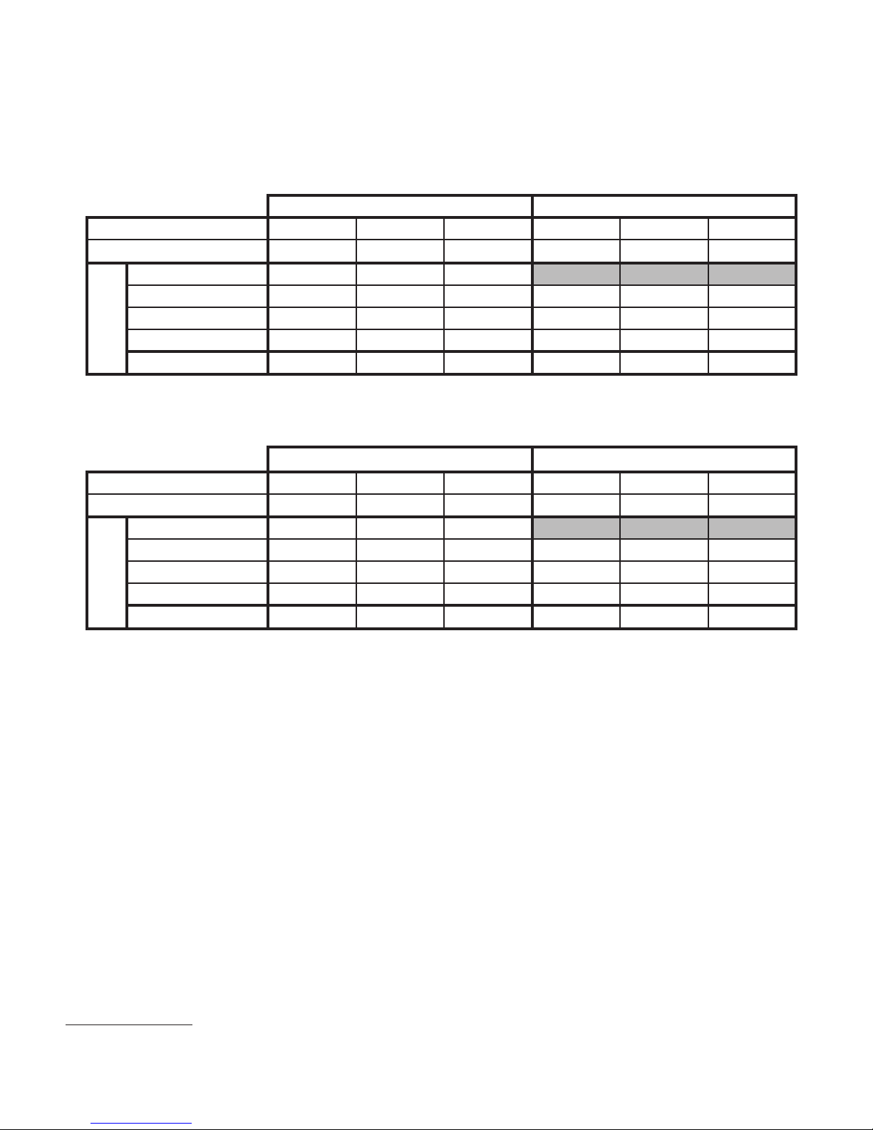
Table 1 shows the order of the cycles when the valve is set up as a softener. When the WS1 or WS1.25 control valve is used
as a down ow softener, two backwashes always occur. When the WS1 or WS1.25 control valve is used as an up ow softener,
only one backwash occurs after brining. The OEM has the option of having the regenerant re ll after the rinse cycle or
have the regenerant pre ll before re gen er a tion. If the OEM chooses to have the regenerant pre ll before regeneration, the
pre ll starts two hours before the re gen er a tion time set. During the 2-hour period in which the brine is being made, treated
(softened) water is still available. For example: regeneration time = 2:00 am, pre ll option selected, down ow softener. Fill
occurs at 12:00 a.m., start of backwash cycle occurs at 2:00 a.m.
Table 1
Regeneration Cycles Softening
WS1 & WS1.25 Downfl ow
Regenerant Refi ll After
Rinse
st
1
Cycle: Backwash
nd
2
Cycle: Regenerate
rd
3
Cycle: Backwash
th
Cycle: Rinse
4
th
5
Cycle: Fill/Dissolve
th
6
Cycle: Service
WS1 & WS1.25 Downfl ow
Regenerant Prefi ll
st
1
Cycle: Fill/Dissolve
nd
2
Cycle: Backwash
rd
3
Cycle: Regenerate
th
Cycle: Backwash
4
th
5
Cycle: Rinse
th
6
Cycle: Service
WS1 & WS1.25
Upfl ow Regenerant
Refi ll After Rinse
st
1
Cycle: Regenerate
nd
2
Cycle: Backwash
rd
3
Cycle: Rinse
th
Cycle: Fill/Dissolve
4
th
5
Cycle: Service
WS1 & WS1.25
Upfl ow Regenerant
Prefi ll
st
1
Cycle: Fill/Dissolve
nd
2
Cycle: Regenerate
rd
3
Cycle: Backwash
th
Cycle: Rinse
4
th
5
Cycle: Service
1
Noryl is a trademark of Sabic Innovative Plastics IP B.V. Company
Page 5
WS1 & 1.25 Man u al Page 5
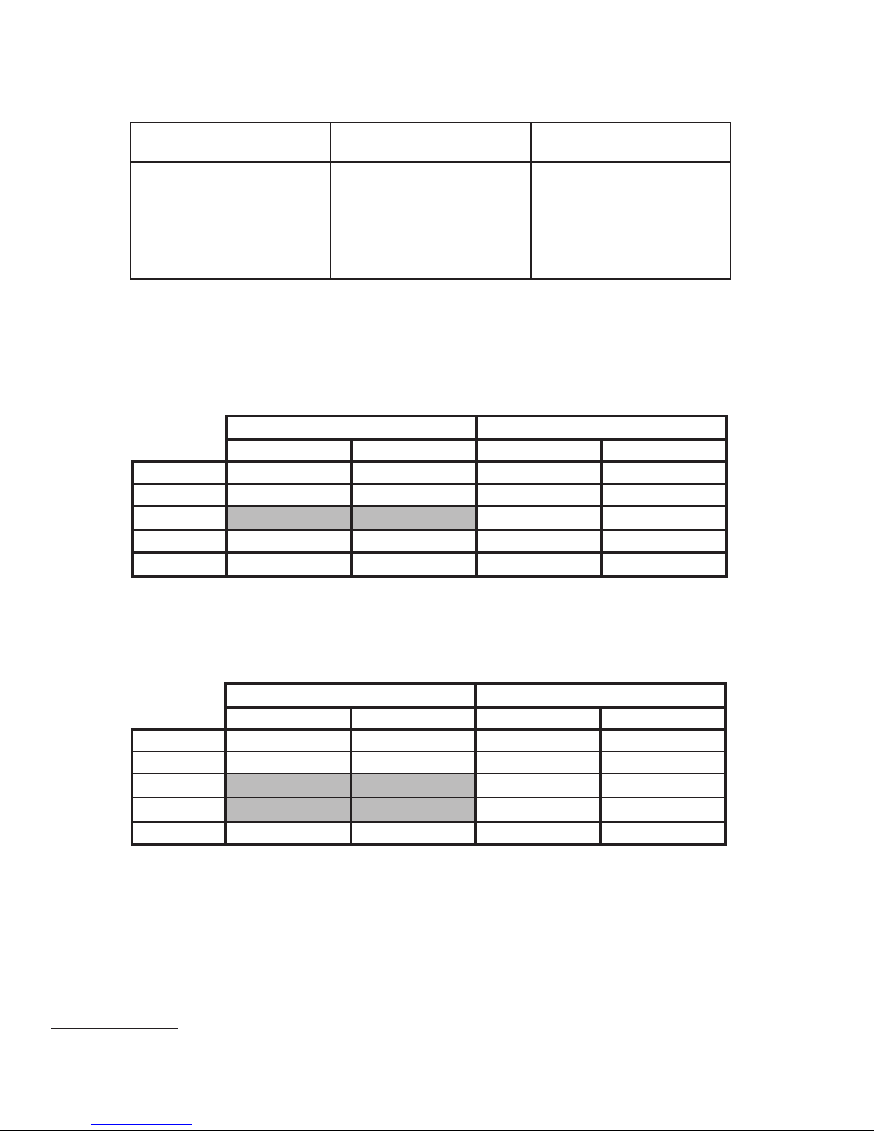
When set up as a softener the backwash and rinse cycles automatically increase with increasing salt dosage. Backwashes can
be set to be NORMAL or LONGER. The option selected will apply to all backwashes. Tables 2 and 3 show the length of the
cycles when the valve is set up as a softener.
Table 2
Backwash Normal Length Softener
Cycle Times in Minutes
WS1 & WS1.25 Downfl ow Softener WS1 & WS1.25 Upfl ow Softener
Grains Capacity/lb NaCl 6000 to 3501 3500 to 2501 2500 to 1700 6000 to 3501 3500 to 2501 2500 to 1700
2
lbs NaCl/cu ft resin
Backwash Normal 6 8 8
Regenerate 45 60 75 45 60 75
Backwash Normal 3 8 10 6 10 12
Rinse 346346
in Minutes
Cycle time
3
Total
Less than 7.5 7.5 to 12 More than 12 Less than 7.5 7.5 to 12 More than 12
57 80 99 54 74 93
Table 3
Backwash Longer Length Softener
Cycle Times in Minutes
WS1 & WS1.25 Downfl ow Softener WS1 & WS1.25 Upfl ow Softener
Grains Capacity/lb NaCl 6000 to 3501 3500 to 2501 2500 to 1700 6000 to 3501 3500 to 2501 2500 to 1700
2
lbs NaCl/cu ft resin
Less than 7.5 7.5 to 12 More than 12 Less than 7.5 7.5 to 12 More than 12
Backwash Longer 8 10 12
Regenerate 45 60 75 60 70 80
Backwash Longer 8 10 12 12 14 16
in Minutes
Rinse 468579
Cycle time
Total
3
65 86 107 77 91 105
Table 4 shows the order of the cycles when the valve is set up as a lter. When the control valve is used as a down ow
re gen er at ing lter, the OEM has the option to specify one backwash or two backwashes. If the control valve is set to
regenerate for a lter, the OEM has the option of having the regenerant re ll after the rinse cycle or have the regenerant pre ll
before regeneration. If the OEM chooses to have the regenerant pre ll before regeneration, the pre ll starts two hours before
the regeneration time set. During the 2-hour period in which the regenerant is being made, treated water is still available. For
example: regeneration time = 2:00 am, pre ll option selected, down ow lter. Fill occurs at 12:00 a.m., start of backwash
cycle occurs at 2:00 a.m. There is only one rinse. Backwashes can be set to normal or longer. The option selected will apply to
all backwashes. Tables 5 and 6 show the length of the cycles when the valve is set up as a lter.
When the control valve is used as a non-regenerating lter, the OEM has the option to specify one backwash or two
backwashes. If two backwashes are speci ed, two rinses occur. Tables 5 and 6 show the length of the cycles when the valve
is set up as a lter. When used as a non-regenerating lter, the down ow piston must be installed, the regenerant piston
removed, injector plugs must be installed in both the DN and UP injector locations and the re ll elbow must be replaced with
a re ll port plug.
2
These are reference numbers that approximate the amount of salt needed. The actual capacity in grains per pound of salt is
used in cal cu la tions.
3
Total time does not include ll time, which is dependent upon the amount of salt needed. When in the ll mode the system
is providing treated water.
Page 6
Page 6 WS1 & 1.25 Man u al
Table 4
Regeneration Cycles Filtering
WS1 & WS1.25 Downfl ow
Regenerant Refi ll After Rinse
st
1
Cycle: Backwash
nd
2
Cycle: Regenerate
rd
3
Cycle: Second Backwash*
th
4
Cycle: Rinse
th
Cycle: Fill
5
th
6
Cycle: Service
WS1 & WS1.25 Downfl ow
Regenerant Prefi ll
st
1
Cycle: Fill
nd
2
Cycle: Backwash
rd
3
Cycle: Regenerate
th
4
Cycle: Second Backwash*
th
Cycle: Rinse
5
th
6
Cycle: Service
WS1 & WS1.25
No Regeneration
st
1
Cycle: Backwash
nd
2
Cycle: Rinse
rd
3
Cycle: Second Backwash*
th
4
Cycle: Second Rinse**
th
Cycle: Service
5
*Second backwash is optional
**Second rinse only occurs if Second Backwash option is selected.
Table 5
Regenerating Filter
Cycle Times in Minutes
WS1 & WS1.25 Single Backwash WS1 & WS1.25 Double Backwash
Normal Longer Normal Longer
Backwash 14 16 8 12
Regenerate 60 60 60 60
2nd Backwash
10 12
Rinse 8 10 8 10
Total
4
82 86 86 94
WS1 & WS1.25 Single Backwash WS1 & WS1.25 Double Backwash
Normal Longer Normal Longer
Backwash 14 16 8 12
Rinse 8 10 6 6
2nd Backwash
nd
2
Rinse
Total 22 26 32 40
The control valve with a water meter can be set for Demand Initiated Regeneration (DIR) only, Time Clock operation only
or DIR and Time Clock which ever comes rst, depending upon what settings are selected for Day Override and Gallon
Capacity.5 See Table 7.
If a control valve does not contain a meter, the valve can only act as a time clock, and day override should be set to any
number and gallon capacity should be set to off.
4
Total time does not include ll time, which is dependent upon the amount of ll needed. When in the ll mode the system is
providing treated water.
5
See Installer Display Settings Step 3I, OEM Softener Setup Step 6S and OEM Filter Setup Step 5F for ex pla na tions of Day
Over ride and Gallon Capacity.
Table 6
Non-Regenerating Filter
Cycle Times in Minutes
10 12
810
Page 7
WS1 & 1.25 Man u al Page 7
Table 7
DIR/Time Clock Options
6
Gallon
Capacity
Any
Number
Auto
Any
Number
Off
DIR
Time
Clock
Reserve Capacity Softener
Regenerant
Filter
Backwash
Only
Settings
Day
Override
Yes Automatically Calculated Yes Off Auto
Ye s
Yes Yes Automatically Calculated Yes
Ye s Ye s
For DIR Softeners, there are two options for setting the Gallons Capacity. The Gallons Capacity is automatically calculated if
set to AUTO. Reserve Capacity is automatically estimated based on water usage if AUTO is used. The other option is to set the
Gallons Capacity to a speci c number. If a speci c number is set, reserve capacity is zero, unless the value is manually set (i.e. the
man u fac tur er intentionally sets the gallon capacity number below the calculated capacity of the system).
If desired enter a value less
than estimated capacity
If desired enter a value less
than estimated capacity
Ye s Ye s Ye s O ff
Ye s Ye s Ye s
Yes None Yes Yes Yes
Any
Number
Any
Number
Any
Number
The WS1 & WS1.25 control valves can also be set to regenerate immediately or at the next regeneration time by changing the
Regeneration Time Option. There are three choices for settings:
1. “NORMAL” means regeneration will occur at the preset regeneration time.
2. “on 0” means regeneration will occur when the gallons capacity reaches zero.
3. “NORMAL + on 0” means the regeneration will occur at the preset regeneration time unless the gallons capacity reaches zero.
If the gallons capacity reaches zero the regeneration will begin 10 minutes after no water usage.
The user can initiate manual regeneration. The user has the option to request the manual regeneration at the delayed regeneration
time or to have the regeneration occur immediately:
1. Press and release REGEN. “Regen Today” will ash on the display and the regeneration will occur at the delayed re gen er a tion
time. The user can cancel the request by pressing and releasing REGEN. This method of manually initiating regeneration is not
allowed when the system is set to “on 0”, i.e. to immediately regenerate when the gallon capacity reaches zero.
2. Pressing and holding REGEN for approximately 3 seconds will immediately start the regeneration. The user cannot cancel this
request, except by resetting the control by pressing NEXT and REGEN simultaneously for 3 seconds.
A unique feature of this control valve is the ability to display actual water usage for the last 63 days. The values are initially stored as
“----”. This means the value is unknown. As days pass values are stored as “0” for no ow or the actual number of gallons. The
counting of the gallons starts at the regeneration time. If no regeneration time can be set (i.e. when the valve is set for immediate
regeneration) the counting of gallons starts at 12 a.m. Day 1 is yesterday, day 2 the day before yesterday, etc.
Another unique feature is that the valve automatically calculates a reserve capacity when set up as a softener with “Gallons
Ca pac i ty” set to “AUTO” and the “Regeneration Time Option” set to “Normal” or “Normal + on 0”. The actual reserve capacity
is com pared to the gallons capacity remaining immediately prior to the preset regeneration time. A regeneration will occur if the
actual reserve capacity is less than the gallons capacity remaining. The actual reserve capacity is calculated by using the estimated
reserve capacity and adjusting it up or down for actual usage.
The estimated reserve capacity for a given day of the week is the maximum value stored for the last three non-trivial water usages
(i.e. more than 20 gallons/day) in seven day intervals.
6
Day Override and Gallon Capacity cannot be set to “oFF” at the same time.
Page 8

Page 8 WS1 & 1.25 Man u al
OEM General In struc tions
The control valve offers multiple procedures that allow the valve to be modi ed to suit the needs of the installation. These
pro ce dures are:
OEM Softener Setup
OEM Filter Setup
Installer Displays & Settings
User Displays & Settings
Diagnostics
Valve History
These procedures can be accessed in any order. Details on each of the procedures are provided on the following pages.
At the discretion of the manufacturer, the eld technician can access all settings. To “lock out” access to diagnostic and valve
history displays and modi cations to settings except hardness, day override, time of regeneration and time of day by anyone
but the manufacturer, press ▼, NEXT, ▲, and SET CLOCK in sequence after settings are made. To “unlock”, so other
displays can be viewed and changes can be made, press ▼, NEXT, ▲, and SET CLOCK in sequence.
When in operation normal user displays such as time of day, gallons remaining or days remaining before regeneration are
shown. When stepping through a procedure, if no buttons are pressed within ve minutes the display returns to a normal user
display. Any changes made prior to the ve minute time out are incorporated.
To quickly exit OEM Softener Setup, OEM Filter Setup, Installer Display Settings, Diagnostics or Valve History press SET
CLOCK. Any changes made prior to the exit are incorporated.
When desired all information in Diagnostics may be reset to zero when the valve is moved to a new location. To reset to zero,
press NEXT and ▼ simultaneously to go to the Service/OEM 1 screen, and release. Press ▲ and ▼ simultaneously to reset
diagnostic values to zero. Screen will return to User Display.
Sometimes it is desirable to have the valve initiate and complete two regenerations within 24 hours and then return to
the preset regeneration procedure. It is possible to do a double regeneration if the control valve is set to “NORMAL” or
“NORMAL + on 0” in Step 9S or Step 7F. To do a double regeneration:
1. Press REGEN once. REGEN TODAY will ash on the display.
2. Press and hold REGEN for three seconds until the valve regeneration initiates.
Once the valve has completed the immediate regeneration, the valve will regenerate one more time at the preset regeneration
time.
Page 9

WS1 & 1.25 Man u al Page 9
STEP 1S
OEM Softener System Setup Quick Reference
STEP 2S
STEP 3S
STEP 4S
STEP 5S
STEP 6S
This is a quick reference setup procedure. See OEM Softener System Setup Detail for
more information on available settings.
STEP 1S – Press NEXT and ▼ simultaneously for 3 seconds. If screen in step 2S does
not appear in 5 seconds the lock on the valve is activated. To unlock press ▼, NEXT,
▲, and SET CLOCK in se quence, then press NEXT and ▼ si mul ta neous ly for 3
seconds.
STEP 2S – Choose Softening using ▼ or ▲. Press NEXT to go to Step 3S. Press
REGEN to exit OEM Softener System Setup.
STEP 3S – Enter the ion exchange capacity in grains of hardness as
calcium carbonate for the system based on test data using ▼ or ▲.
Press NEXT to go to Step 4S. Press REGEN to return to previous
step.
STEP 4S – Enter the pounds of salt per regeneration using ▼ or ▲.
Press NEXT to go to Step 5S. Press REGEN to return to previous
step.
STEP 5S – Backwash: Select “NORMAL” or “LONGER” using ▼ or ▲. See Tables
2 or 3 for backwash times. Press NEXT to go to Step 6S. Press REGEN to return to
previous step.
STEP 6S – Set Gallons Capacity using ▼ or ▲:
• “AUTO” (reserve capacity automatically estimated and gallons capacity
au to mat i cal ly calculated from grains capacity and water hardness);
• “oFF” (regeneration based on day override); or
• number of gallons (20 to 50,000).
See Setting Options Table for more detail. Press NEXT to go to Step 7S. Press REGEN
to return to previous step.
STEP 7S
STEP 8S
STEP 9S
RETURN TO
NORMAL MODE
STEP 7S – Set Re ll option using ▼ or ▲:
• “PoST” to re ll the brine tank after the nal rinse; or
• “PrE” to re ll the brine tank two hours before the regeneration time set.
Press NEXT to go to Step 8S. Press REGEN to return to previous step.
STEP 8S – Set regenerant down ow or up ow using ▼ or ▲:
• “dn” if the regenerant is to ow downward through the media; or
• “UP” if the regenerant is to ow upward through the media.
Prior to selecting a regenerant fl ow direction, verify the correct valve body, main piston,
regenerant piston, and stack are being used, and that the injector or injector plug(s) are in
the correct locations. See Valve Body Compliance Table in WS1 & WS1.25 Drawings and
Service Manual.
Press NEXT to go to Step 9S. Press REGEN to return to previous step.
STEP 9S – Set Regeneration Time Option using ▼ or ▲:
• “NORMAL” means regeneration will occur at the preset time;
• “on 0” means regeneration will occur immediately when the gallons capacity
reaches 0 (zero); or
• “NORMAL + on 0” means regeneration will occur at one of the following:
• the preset time when the gallons capacity falls below the reserve or the
spec i ed number of days between regenerations is reached which ev er comes
rst; or
• after 10 minutes of no water usage when the gallon capacity reaches 0 (zero).
See Setting Options Table for more detail. Press NEXT to exit OEM Softener System
Setup. Press REGEN to return to previous step.
Page 10
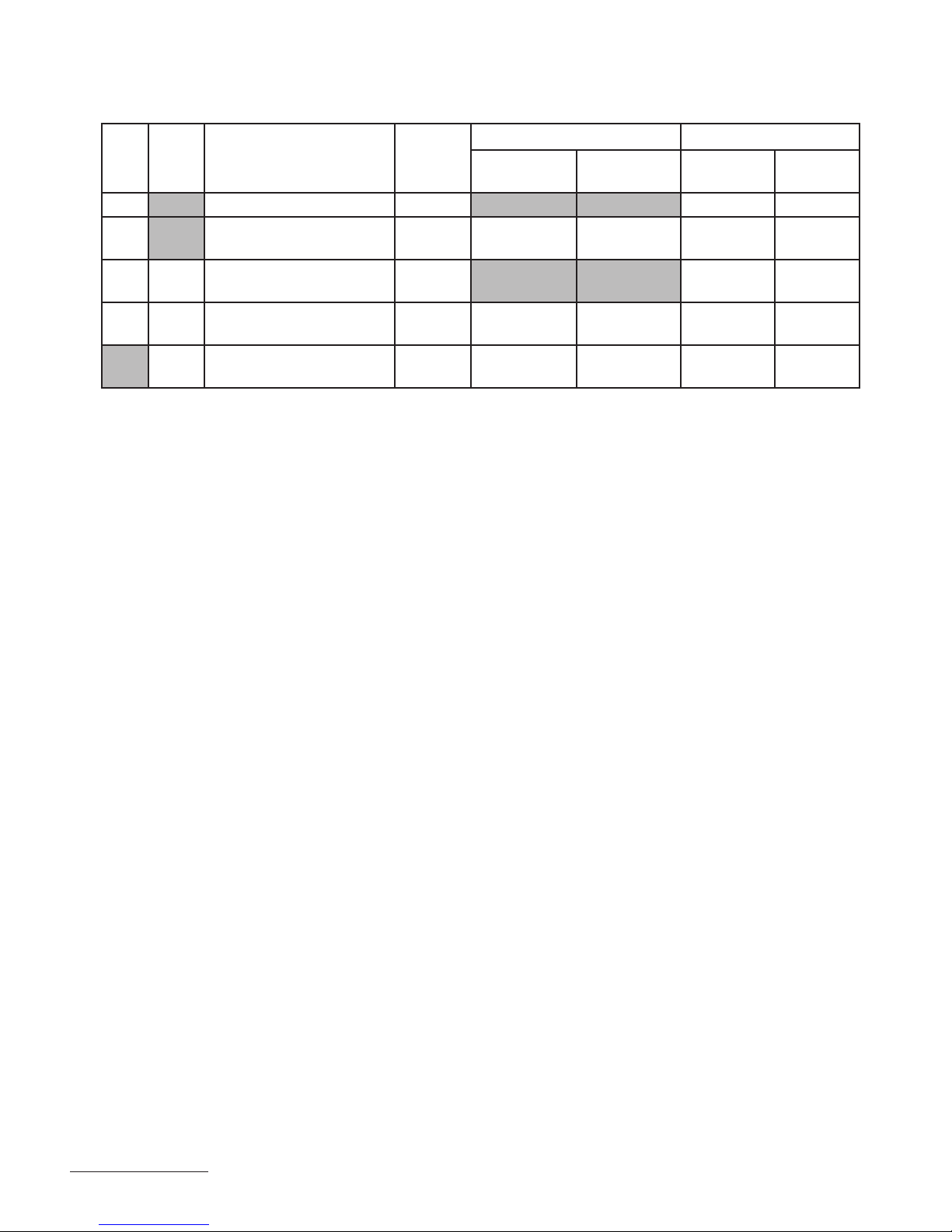
Page 10 WS1 & 1.25 Man u al
Setting Options Table
Filters should only use shaded options.
Volume
Capacity
Regeneration
Time Option
Day
Override
AUTO NORMAL oFF
AUTO NORMAL
Any
number
NORMAL oFF
oFF NORMAL
Any
number
NORMAL
Any
number
Any
number
Any
number
AUTO On 0 oFF
7
Result
Reserve capacity automatically estimated.
Regeneration occurs when volume capacity falls below the reserve
capacity at the next Regen Set Time
Reserve capacity automatically estimated.
Regeneration occurs at the next Regen Set Time when volume capacity
falls below the reserve capacity or the specifi ed number of days between
regenerations is reached.
Reserve capacity not automatically estimated.
Regeneration occurs at the next Regen Set Time when volume
capacity reaches 0.
Reserve capacity not automatically estimated.
Regeneration occurs at the next Regen Set Time when the specifi ed
number of days between regenerations is reached.
Reserve capacity not automatically estimated.
Regeneration occurs at the next Regen Set Time when volume
capacity reaches 0 or the specifi ed number of days between
regenerations is reached.
Reserve capacity not automatically estimated.
Regeneration occurs immediately when volume capacity reaches 0.
Time of regeneration will not be allowed to be set because regeneration
will always occur when volume capacity reaches 0.
Any
number
On 0 oFF
AUTO NORMAL + on 0 oFF
AUTO NORMAL + on 0
Any
number
NORMAL + on 0
Any
number
Any
number
Reserve capacity not automatically estimated.
Regeneration occurs immediately when volume capacity reaches 0.
Time of regeneration will not be allowed to be set because regeneration
will always occur on 0.
Reserve capacity automatically estimated.
Regeneration occurs when volume capacity falls below the reserve
capacity at the next Regen Set Time or regeneration occurs after 10
minutes of no water usage when volume capacity reaches 0.
Reserve capacity automatically estimated.
Regeneration occurs at the next Regen Set Time when volume capacity
falls below the reserve capacity or the specifi ed number of days between
regenerations is reached or regeneration occurs after 10 minutes of no
water usage when volume capacity reaches 0.
Reserve capacity not automatically estimated.
Regeneration occurs at the next Regen Set Time when the specifi ed
number of days between regenerations is reached or regeneration occurs
after 10 minutes of no water usage when volume capacity reaches 0.
7
Reserve capacity estimate is based on history of water usage.
Page 11
WS1 & 1.25 Man u al Page 11
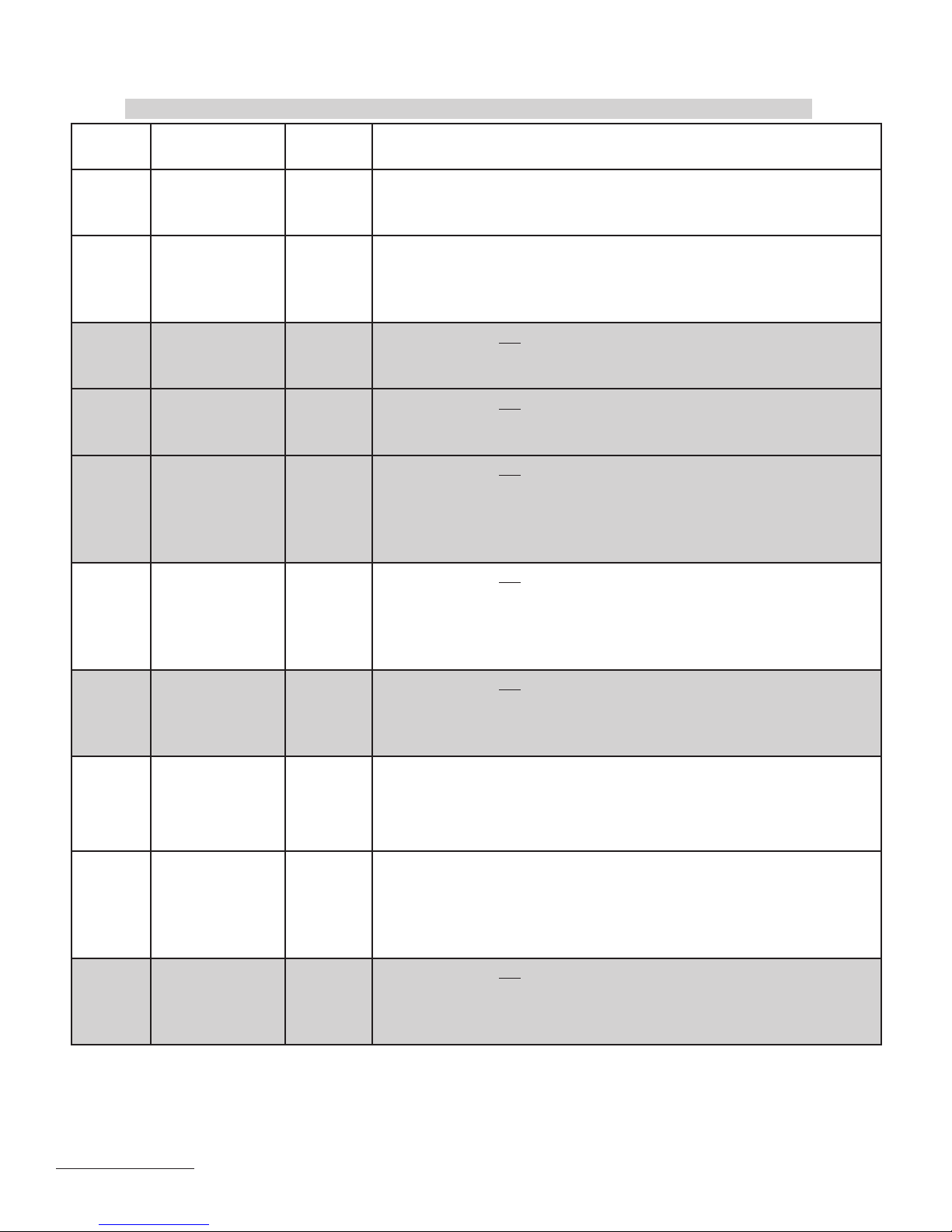
OEM Filter System Setup Quick Reference
This is a quick reference setup procedure. See OEM Filter System Setup Detail for
STEP 1F
STEP 2F
STEP 3F
STEP 4F
more information on available settings.
STEP 1F – Press NEXT and ▼ simultaneously for 3 seconds. If screen in step 2F does
not appear in 5 seconds the lock on the valve is activated. To unlock press ▼, NEXT,
▲, and SET CLOCK in sequence, then press NEXT and ▼ simultaneously for 3
seconds.
STEP 2F – Choose Filtering using ▼ or ▲. Press NEXT to go to step 3F. Press
REGEN to exit OEM Filter System Setup.
STEP 3F – Enter “oFF” if regenerant is not used (i.e. backwash only) or enter the re ll
volume (in gallons) using ▼ or ▲. Prior to selecting oFF or regenerant volume, verify the
correct valve body, main piston, regenerant piston, and stack are being used, and that the
injector or injector plug(s) are in the correct locations. See Compliance Table in Service
Instructions under Injector Cap, Screen, Injector Plug and Injector section and Figure 6.
Press NEXT to go to step 4F. Press REGEN to return to previous step.
STEP 4F – Backwash: Select using ▼ or ▲:
• “NORMAL” for one “NORMAL” backwash (14 minutes);
• “NORMAL 2” for two “NORMAL” backwashes (8 minutes each);
• “LONGER” for one “LONGER” backwash (16 minutes); or
• “LONGER 2” for two “LONGER” backwashes (12 minutes each).
See Tables 5 and 6 for additional details. Press NEXT to go to step 5F. Press REGEN
to return to previous step.
RETURN TO
NORMAL MODE
STEP 5F
STEP 6F
STEP 7F
STEP 5F – Set Gallons Capacity using ▼ or ▲:
• “oFF” (regeneration based on day override); or
• number of gallons (20 to 50,000).
See Setting Options Table for more detail. Press NEXT to go to step 6F. Press REGEN
to return to previous step.
STEP 6F – Set Re ll option using ▼ or ▲:
• “PoST” to re ll the brine tank after the nal rinse; or
• “PrE” to re ll the brine tank two hours before the re gen er a tion time set.
Press NEXT to go to step 7F. Press REGEN to return to previous step.
STEP 7F – Set Regeneration Time Option using ▼ or ▲:
• “NORMAL” means regeneration will occur at the preset time;
• “on 0” means regeneration will occur immediately when the gallons capacity
reaches 0 (zero); or
• “NORMAL + on 0” means regeneration will occur at one of the following:
• the preset time when the speci ed number of days between regenerations is
reached; or
• after 10 minutes of no water usage when the gallon capacity reaches 0 (zero).
This display will not appear if Step 5F is set to oFF.
See Setting Options Table for more detail. Press NEXT to exit OEM Filter System
Setup. Press REGEN to return to previous step.
Page 12

Page 12 WS1 & 1.25 Man u al
Installer Display Settings
STEP 1I
STEP 2I
STEP 3I
STEP 4I
STEP 5I
STEP 1I - Press NEXT and ▲ simultaneously for 3 seconds.
STEP 2I – Hardness: Set the amount of hardness in grains of hardness as
calcium car bon ate per gallon using ▼ or ▲. The default is 20 with value
ranges from 1 to 150 in 1 grain increments. Note: The grains per gallon can
be in creased if soluble iron needs to be reduced. This display will show “–
nA–” if “FILTER” is selected in Step 2F or if ‘AUTO’ is not selected in Step
6S. Press NEXT to go to step 3I. Press REGEN to exit Installer Dis play
Settings.
STEP 3I – Day Override: When gallon capacity is set to off, Day Override sets the
number of days between re gen er a tions. When gallon capacity is set to AUTO or to
a number, Day Override sets the max i mum number of days between re gen er a tions.
If value set to “oFF” re gen er a tion initiation is based solely on gallons used. If value
is set as a number (allowable range from 1 to 28) a re gen er a tion initiation will be
called for on that day even if suf cient number of gallons were not used to call for a
regeneration. Set Day Override using ▼ or ▲:
• number of days between regeneration (1 to 28); or
• “oFF”.
See Setting Options Table for more detail on setup. Press NEXT to go to step 4I. Press
REGEN to return to previous step.
STEP 4I – Next Regeneration Time (hour): Set the hour of day for regeneration using
▼ or ▲. AM/PM toggles after 12. The default time is 2:00 a.m. This display will show
“REGEN on 0 GAL” if “on 0” is selected in Step 9S or Step 7F. Press NEXT to go to
step 5I. Press REGEN to return to previous step.
STEP 5I – Next Regeneration Time (minutes): Set the minutes of day for regeneration
using ▼ or ▲. This display will not be shown if “on 0” is selected in Step 9S or Step
7F. Press NEXT to exit Installer Display Settings. Press REGEN to return to previous
step.
To initiate a manual regeneration immediately, press and hold REGEN for three
RETURN TO
NORMAL MODE
seconds. The system will begin to re gen er ate im me di ate ly. The control valve may be
stepped through the various re gen er a tion cycles by pressing REGEN.
User Display Settings
General Operation
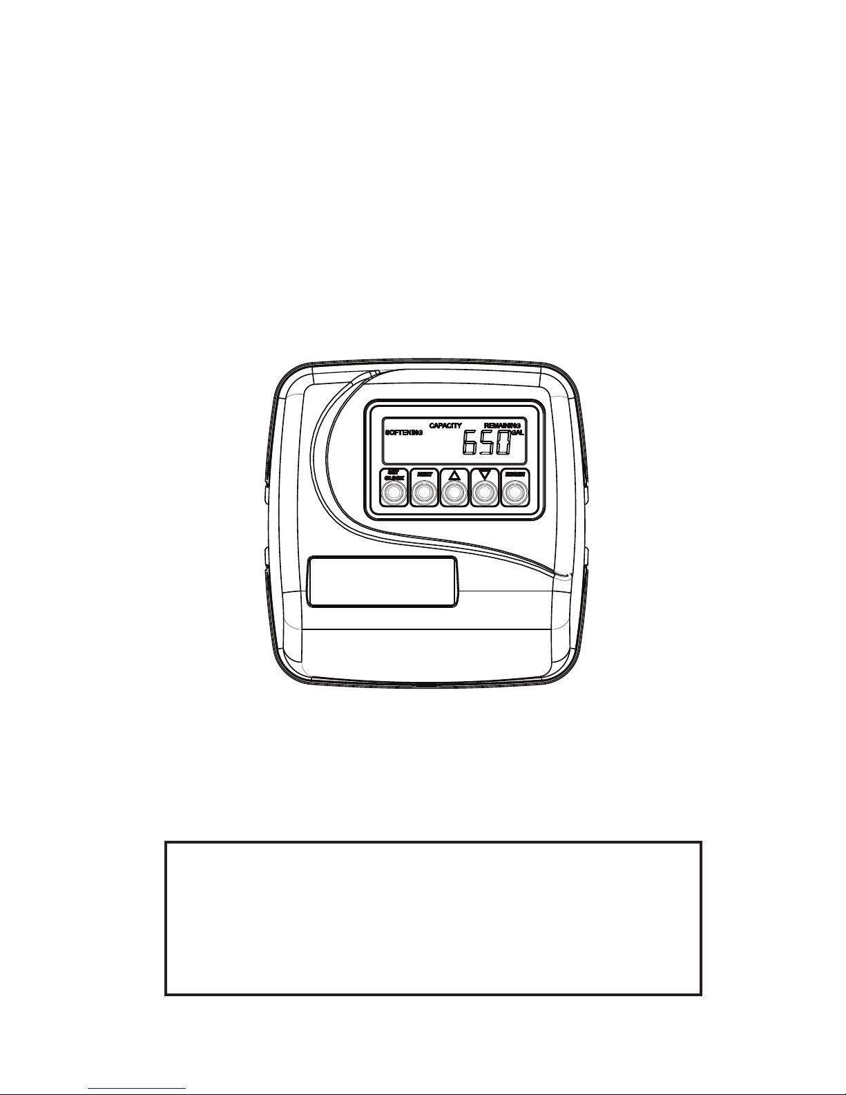
When the system is operating one of two displays will
be shown. Press ing NEXT will alternate between the
dis plays. One of the displays is always the current time
of day. The second display is one of the fol low ing: days
remaining or gallons remaining. Days remaining is the
number of days left before the system goes through a
regeneration cycle. Ca pac i ty remaining is the number
of gallons that will be treated before the system goes
through a regeneration cycle. The user can scroll
between the displays as desired.
If the system has called for a regeneration that will
occur at the preset time of re gen er a tion, the words
REGEN TODAY will appear on the display.
OR
REGEN TODAY
will be displayed if
a regeneration is
expected “Tonight.”
When water is being treated (i.e. water is owing
through the system) the word “Soft en ing” or
“Fil ter ing” ashes on the display if a water meter is
installed.
Page 13

WS1 & 1.25 Man u al Page 13
Regeneration Mode
Typically a system is set to regenerate at a time of low water usage. An example of a time
with low water usage is when a household is asleep. If there is a demand for water when
the system is regenerating, untreated water will be used.
When the system begins to regenerate, the display will change to include information about the step of the regeneration
process and the time remaining for that step to be completed. The system runs through the steps au to mat i cal ly and will reset
itself to provide treated water when the regeneration has been completed.
Manual Regeneration
Sometimes there is a need to regenerate the system sooner
than when the system calls for it, usually referred to as manual
re gen er a tion. There may be a period of heavy water usage
because of guests or a heavy laundry day.
To initiate a manual regeneration at the preset delayed
regeneration time, when the regeneration time option is set to “NORMAL” or “NORMAL
+ on 0”, press and release REGEN. The words “REGEN TO DAY” will ash on the
display to indicate that the system will re gen er ate at the preset delayed re gen er a tion time. If
you pressed REGEN in error, pressing the button again will cancel the request. Note: If the regeneration time option is set to
“on 0” there is no set delayed regeneration time so “REGEN TODAY” will not activate if REGEN is pressed.
REGEN TODAY will
Flash if a regeneration
is expected “Tonight.”
To initiate a manual regeneration immediately, press and hold REGEN for three seconds. The system will begin to regenerate
immediately. The request cannot be cancelled.
Note: For softeners, if brine tank does not contain salt, ll with salt and wait at least two hours before regenerating.
Set Time of Day
STEP 1U
The user can also set the time of day. Time of day should only need to be set after power
outages lasting more than 8 hours, if the battery has been depleted and a power outage
occurs, or when daylight saving time begins or ends. If a power outage lasting more than
STEP 2U
8 hours occurs, the time of day will ash on and off which indicates the time of day
should be reset. If a power outage lasts less than 8 hours and the time of day ashes on
and off, the time of day should be reset and the battery replaced.
STEP 1U – Press SET CLOCK.
STEP 3U
STEP 2U - Current Time (hour): Set the hour of the day using ▼ or ▲. AM/PM toggles
after 12. Press NEXT to go to step 3U.
STEP 3U - Current Time (minutes): Set the minutes of the day using ▼ or ▲. Press
NEXT to exit Set Clock. Press REGEN to return to previous step.
Power Loss
If the power goes out, the system will keep time for up to 8 hours or until the battery is depleted. If a power outage of more
than 8 hours occurs, the time of day will ash on and off which indicates the time of day should be reset. The system will
remember the rest. If a power outage lasts less than 8 hours and the time of day ashes on and off, the non rechargeable
battery should be replaced.
Error Message
If the word “ERROR” and a number are alternately ashing on the display
contact the OEM for help. This indicates that the valve was not able to function
properly.
Page 14
Page 14 WS1 & 1.25 Man u al
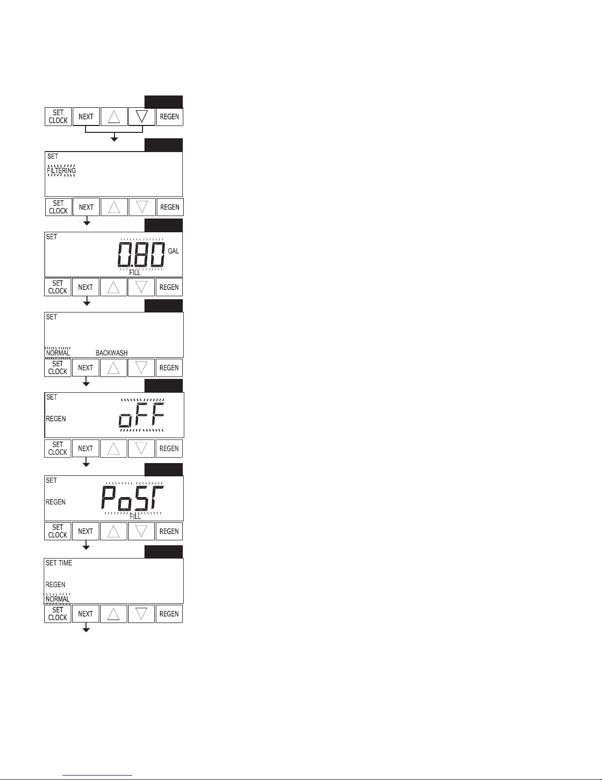
STEP 1D
Diagnostics
STEP 1D – Press ▼ or ▲ simultaneously for three seconds. If screen in step 2D does not
STEP 2D
STEP 3D
STEP 4D
STEP 5D
STEP 6D
appear in 5 seconds the lock on the valve is activated. To unlock press ▼, NEXT, ▲, and
SET CLOCK in sequence, then press NEXT and ▼ simultaneously for 3 seconds.
STEP 2D – Days, since last regeneration: This display shows the days since the last
re gen er a tion occurred. Press NEXT to go to Step 3D. Press REGEN to exit Diagnostics.
STEP 3D – Gallons, since last regeneration: This display shows the number of gallons that
have been treated since the last re gen er a tion. This display will equal zero if a water meter is
not installed. Press NEXT to go to Step 4D. Press REGEN to return to previous step.
STEP 4D – Gallons, reserve capacity used for last 7 days: If the valve is set up as a softener,
a meter is installed and Set Gallons Capacity is set to “Auto,” this display shows 0 day
(for today) and ashes the reserve capacity. Press ing ▲ will show day 1 (which would be
yesterday) and ashes the reserve capacity used. Press ing ▲ again
will show day 2 (the day before yesterday) and the
reserve capacity. Keep pressing ▲ to show the gallons
for days 3, 4, 5 and 6. ▼ can be pressed to move
back wards in the day series. Press NEXT at any time
to go to Step 5D. Press REGEN to return to previous
step.
STEP 5D - Gallons, 63 day usage history: This display
shows day 1 (for yesterday) and ashes the number of
gallons treated yesterday. Pressing ▲ will show day 2
(which would be the day before yesterday) and ashes
the number of gallons treated on that day. Con tin ue
to press ▲ to show the max i mum number of gallons
treated for the last 63 days. This display will show dashes if a water meter is not installed.
Press NEXT at any time to go to Step 6D. Press REGEN to return to previous step.
STEP 7D
STEP 8D
STEP 9D
STEP 10D
STEP 6D – Flow rate, current: The ow rate in gallons per minute will be displayed. If ow
stops the value will fall to zero in a few seconds. This display will equal zero if a water meter
is not installed. Press NEXT to go to Step 7D. Press REGEN to return to previous step.
STEP 7D – Flow rate, maximum last seven days: The maximum ow rate in gallons per
minute that occurred in the last seven days will be displayed. This display will equal zero
if a water meter is not installed. Press NEXT to go to Step 8D. Press REGEN to return to
previous step.
STEP 8D – Gallons, total used since last reset: The total number of gallons used since last
reset will be displayed. This display will equal zero if a water meter is not installed. Press
NEXT to go to Step 9D. Press REGEN to return to previous step.
STEP 9D – Days, total number since last reset: The total number of days the control valve
has been in service since last reset will be displayed. Press NEXT to go to Step 10D. Press
REGEN to return to previous step.
STEP 10D – Regenerations, total number since last reset: The total number of re gen er a tions
that have occurred since last reset will be displayed. Press NEXT to exit Di ag nos tics. Press
REGEN to return to previous step.
When desired, all information in Diagnostics may be reset to zero when the valve is installed in
a new location. To reset to zero, press NEXT and ▼ simultaneously to go to the Service/OEM
RETURN TO
NORMAL MODE
screen, and release. Press ▼ and ▲ simultaneously to reset diagnostic values to zero. Screen
will return to user display.
Page 15
WS1 & 1.25 Man u al Page 15
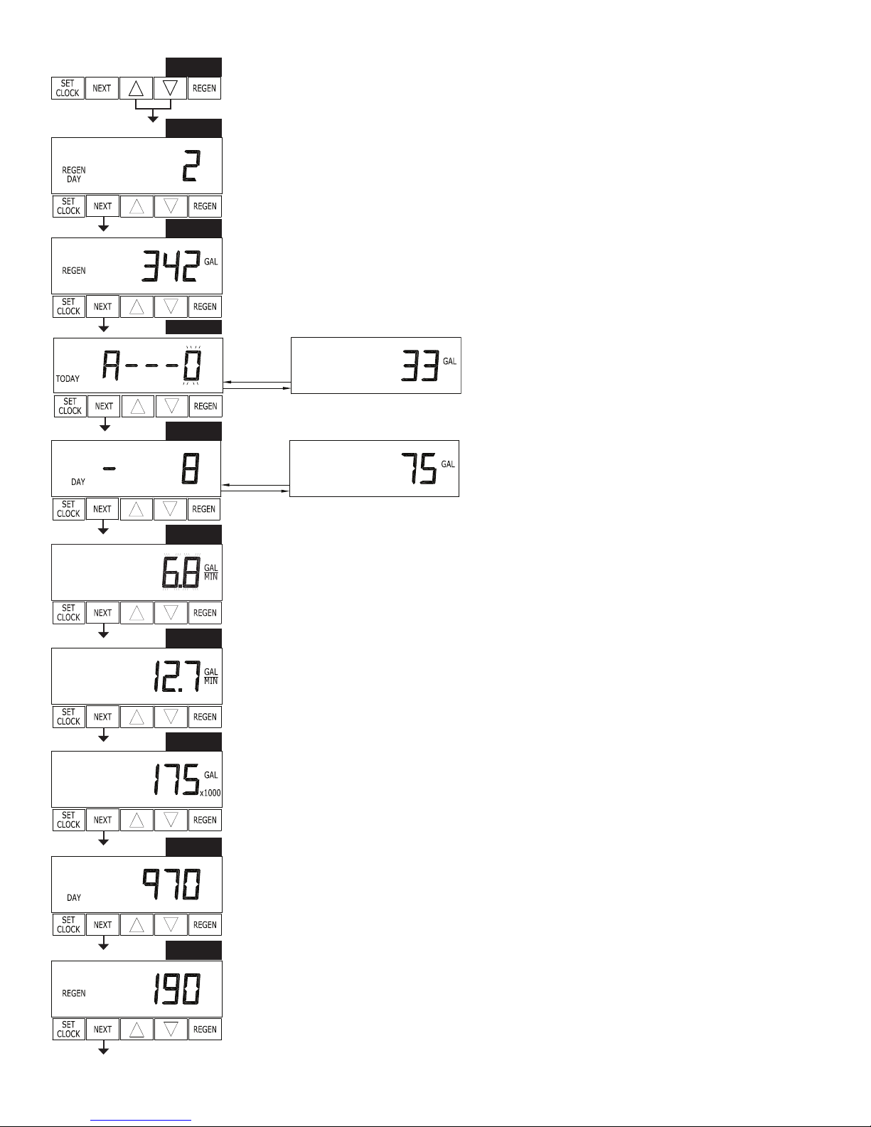
Valve History
STEP 1VH
STEP 1VH
STEP 2VH
STEP 3VH
STEP 4VH
STEP 1VH – Press ▲ and ▼ simultaneously for three seconds and release. Then
press ▲ and ▼ si mul ta neous ly and release. If screen in step 2VH does not appear in
5 seconds the lock on the valve is activated. To unlock press ▼, NEXT, ▲, and SET
CLOCK in sequence, then press ▲ and ▼ si mul ta neous ly for 3 seconds and release.
Then press ▲ and ▼ simultaneously and release.
STEP 2VH – Software Version: This display shows the software version of the valve.
Press NEXT to go to Step 3VH. Press REGEN to exit Valve History.
STEP 3VH8 – Flow rate, maximum since startup: This display shows the max i mum
ow rate in gallons per minute that has oc curred since startup. This display will equal
zero if a water meter is not installed. Press NEXT to go to Step 4VH. Press REGEN
to return to previous step.
STEP 4VH – Gallons, total used since start-up: This display shows the total gallons
treated since startup. This display will equal zero if a water meter is not in stalled. Press
NEXT to go to Step 5VH. Press REGEN to return to previous step.
RETURN TO
NORMAL MODE
STEP 5VH
STEP 6VH
STEP 7VH
STEP 5VH – Days, total since start-up: This display shows the total days since startup.
Press NEXT to go to Step 6VH. Press REGEN to return to previous step.
STEP 6VH – Regenerations, total number since start-up: This display shows the total
number of regenerations that have occurred since startup. Press NEXT to go to Step
7VH. Press REGEN to return to previous step.
STEP 7VH – Error Log: This display shows a history of the last 10 errors generated
by the control during operation. Press ▲ or ▼ to review each error recorded. Press
NEXT to exit Valve History. Press REGEN to return to previous step.
8
Values in steps 3VH through 7VH cannot be reset.
Page 16
Page 16 WS1 & 1.25 Man u al
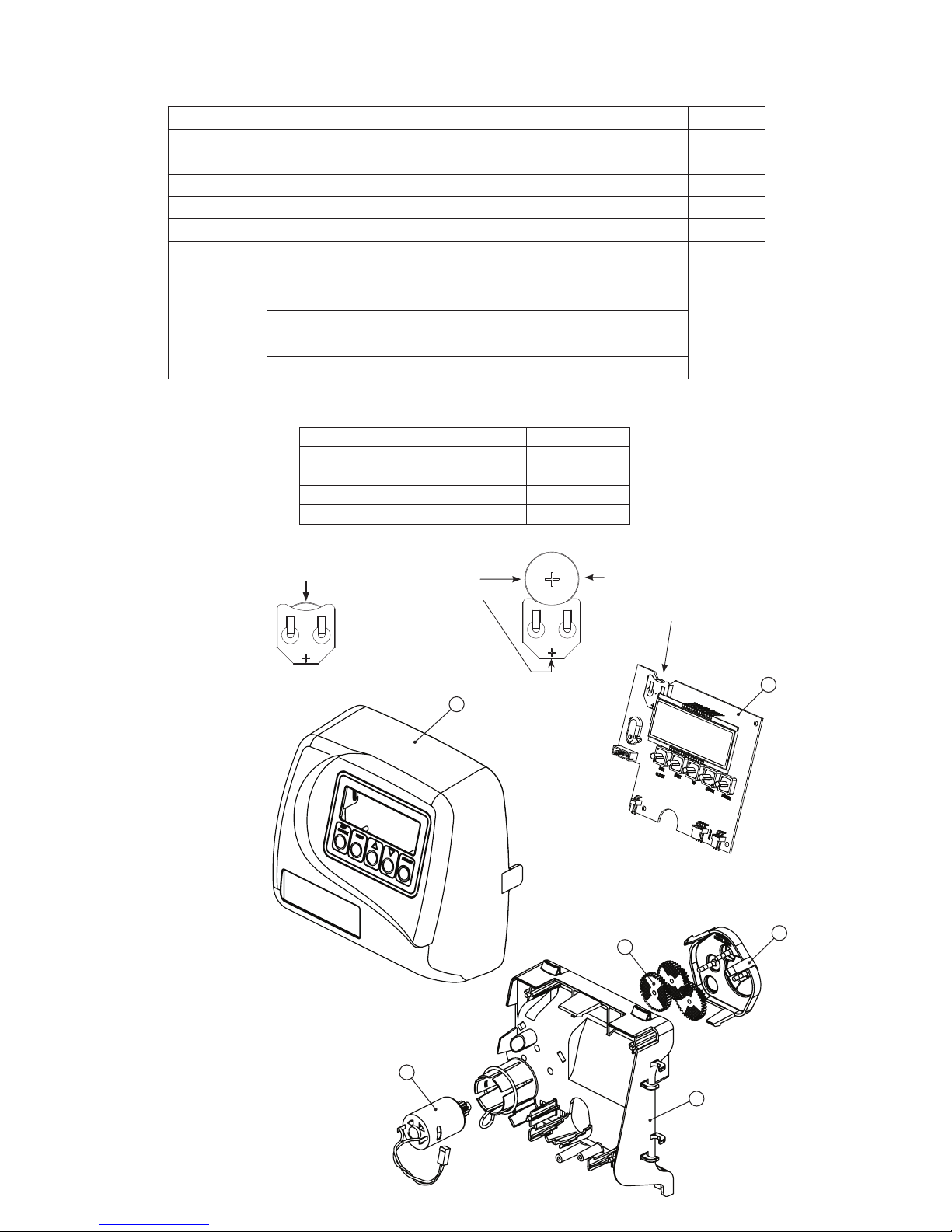
Front Cover and Drive Assembly
Drawing No. Order No. Description Quantity
1 V3175-01 WS1 Front Cover ASY 1
2 V3107-01 WS1 Motor 1
3 V3106-01 WS1 Drive Bracket&Spring Clip 1
4 V3108-10BOARD WS1 PCB XMEGA REPL 1
5 V3110 WS1 Drive Reducing Gear 12x36 3
6 V3109 WS1 Drive Gear Cover 1
V3002 WS1 Drive ASY *
V3186 WS1 AC ADAPTER 120V-12V
Not Shown
V3186EU WS1 AC ADAPTER 220-240V-12V EU
V3186UK WS1 AC ADAPTER 220-240V-12V UK
V3186-01 WS1 AC ADAPTER CORD ONLY
* Drawing number parts 2, 3, 5 and 6 may be purchased as a complete assembly, part V3002.
AC Adapter U.S. International
Supply Voltage 120 V AC 230V AC
Supply Frequency 60 Hz 50 Hz
Output Voltage 12 V AC 12 V AC
Output Current 500 mA 500 mA
1
When replacing the battery, align
positives and push down to fully seat.
Battery Fully Seated
Correct
Battery
Orientation
1
Battery replacement is
3 volt lithium coin cell
type 2032.
4
6
5
2
3
Page 17

WS1 & 1.25 Man u al Page 17
Page 18

Page 18 WS1 & 1.25 Man u al
Page 19

WS1 & 1.25 Man u al Page 19
Page 20

Page 20 WS1 & 1.25 Man u al
Revision History:
5/27/2014
PAGE 13:
New regeneration cycle status display, new error display
PAGE 15:
Step 7VH Error Log: new display
PAGE 16:
V3108-10BOARD WS1/125 PCB XMEGA REPLACE
New board drawing
9/15/2015
PAGE 16:
Drive Bracket & Spring Clip on drawing was labeled incorrectly - changed from 6 to 3.
3/4/2016
PAGE 17:
1 V3005-02 WS1 Spacer Stack Assembly 1
PAGE 18:
1a V3430-01 WS1.5 Spacer Stack Assembly
1b V3005-02 WS1 Spacer Stack Assembly
1
6/20/2016
Removed Drive Assembly and 1”/1.25” identi cation drawings - see Service Manual
7/12/2016
PAGE 8:
Removed: The one exception is current ow rate display under the di ag nos tic procedure. The current ow rate display has a
30 minute time out feature.
PAGE 14:
Step 6D - Removed: Turn the water on at one or more taps in the building.
1/27/2017
PAGE 16:
* Drawing number parts 2, 3, 5 and 6 may be purchased as a complete assembly, part V3002.
Form No. V3115 – 1/27/2017
U.S. Patents: 6,402,944 • 6,444,127 • 6,776,901
 Loading...