


Water Specialist
WS2H and WS3 Control Valve
Manual
HYDROCARBONS SUCH AS KEROSENE, BENZENE, GASOLINE, ETC., MAY DAMAGE
PRODUCTS THAT CONTAIN O-RINGS OR PLASTIC COMPONENTS. EXPOSURE TO SUCH
HYDROCARBONS MAY CAUSE THE PRODUCTS TO LEAK. DO NOT USE THE PRODUCT(S)
CONTAINED IN THIS DOCUMENT ON WATER SUPPLIES THAT CONTAIN HYDROCARBONS
SUCH AS KEROSENE, BENZENE, GASOLINE, ETC.

Page 2 WS2H and WS3 Manual

WS2H and WS3 Manual Page 3
TABLE OF CONTENTS
General Speci cations and Pre-Installation Checklist .................................................... 4
Software and Power Supply Compatibility....................................................................... 5
Communication Cable Connection to PC Board Layout ................................................. 5
Wiring for custom AC Adapter ......................................................................................... 6
Custom Meter Wiring ....................................................................................................... 6
Main PC Board with System Board .................................................................................. 7
Typical System Examples ................................................................................................. 8
Button Function and Programing Key Sequence ........................................................... 10
Programming Quick Reference ...................................................................................... 12
Typical User Screens ...................................................................................................... 14
Setting Time of Day ........................................................................................................ 16
Noti cations ................................................................................................................... 16
Errors .............................................................................................................................. 16
System Setup Screens ................................................................................................... 17
Cycle Setup Screens ...................................................................................................... 22
Timer Screens ................................................................................................................ 24
Installer Setup Screens .................................................................................................. 28
Diagnostic Screens ........................................................................................................ 30
Valve History ................................................................................................................... 34
Custom Motorized Drive Timing ..................................................................................... 35
Installation ...................................................................................................................... 36
Installation Summary ...................................................................................................... 39
Control Positions / Flow Diagrams ................................................................................. 40
Front Cover and Drive Assembly .................................................................................... 43
WS2H Drive Cap Assembly, Down ow Piston, Regenerant Piston,
Spacer Stack Assembly, Drive Back Plate, Main Body and Meter ................................ 44
WS3 Drive Cap Assembly, Down ow Piston, Regenerant Piston,
Spacer Stack Assembly, Drive Back Plate and Main Body............................................ 45
WS2H and WS3 Brine Valve Body and Injector Components ....................................... 46
Standard Injector Graphs ............................................................................................... 47
V3064 WS2H/2QC 4 INCH BASE ASY........................................................................... 49
V3055 WS2H/2QC 6 INCH FLANGE BASE ASY ............................................................ 49
WS2H/2QC SIDE MOUNT BASE ASSEMBLY ................................................................ 49
V3260BSPT-02 WS2H/2QC SIDE MOUNT BASE BSPT ASSEMBLY ............................ 49
Drain Line Flow Controls ................................................................................................ 50
M X F STAINLESS STEEL, 0.7 – 150 GPM ..................................................................... 51
V3764 WS3 DLFC NPT ASY or V3764BSPT WS3 DLFC BSPT ASY ............................. 52
Drain Line Flow Control Washers ................................................................................... 53
WS2H/ WS3 Trouble Shooting Guide ............................................................................. 54

Page 4 WS2H and WS3 Manual
GENERAL SPECIFICATIONS AND PRE-INSTALLATION CHECKLIST
TABLE 1
Minimum/Maximum Operating Pressures 20 psi (138 kPa) -125 psi (862 kPa)
Minimum/Maximum Operating
Temperatures
Power Adapter:
Supply Voltage
Supply Frequency
Output Voltage
Output Current
40°F (4°C) – 110°F (43°C)
U.S.
120V AC
60 Hz
18V, 20V or 24V AC (see Table 2)
800 mA
International
230V AC
50 Hz
18V, 20V or 24V AC
800 mA
No user serviceable parts are on the PC board, the motor, or the Power adapter. The means of disconnection from
the main power supply is by unplugging the Power adapter from the wall.
Service ow rate
Backwash ow rate
CV Service
CV Backwash
WS2H Valve: 125 gpm (473 lpm, 28.4 m
WS3 Valve: 250 gpm (946 lpm, 56.8 m3/h) @ 15 psig (103 kPa) drop
WS2H Valve: 125 gpm (473 lpm, 28.4 m3/h) @ 25 psig (172 kPa) drop
WS3 Valve: 220 gpm (833 lpm, 50.0 m3/h) @ 25 psig (172 kPa) drop
WS2H Valve: 32.3
WS3 Valve: 64.6
WS2H Valve: 25.0
WS3 Valve: 44.0
3/h) @ 15 psig (103 kPa) drop
WS2H Valve:
Meter:
Accuracy
Flow Range
Internal Meter
+ 5 %
1.5 – 125 gpm
WS3 Valve: Optional External Meter
+ 5 %
3.5 – 350 gpm (13.3 – 1325 lpm)
(5.7 – 473 lpm)
Regenerant Re ll Rate
WS2H and WS3 Valves: Variable - Shipped from Factory with 2.2 gpm
(8.33 lpm)
Injectors WS2H & WS3 Valves: See Injector Graphs V3010-2A through 2H
Brine Line Adapters Included 1” Male NPT Elbow & ¾” x 1” Solvent Weld Elbow
Inlet, Outlet and Drain Line Openings
WS2H Valve: 2” Female NPT or BSPT or 2.5” Groove Lock
WS3 Valve: 3” Female NPT or BSPT, No Groove Lock
Female NPT Inlet & Outlet Female BSPT Inlet & Outlet
*Distributor Tube Sizing:
WS2H Valve
WS3 Valve
Tank Connection:
WS2H Valve
WS3 Valve
Shipping Weight
PC Board Memory
Compatible with the following typical
concentrations of regenerants/chemicals
2.375” OD (2.0” NPS)
3.5” OD (3” NPS)
+2.25” -
+2.5”
+2.5” – 2.75”
63 mm OD
90 mm OD
4”-8UN, 6” Flange, Side Mount (2” Female NPT or BSPT or 2.5”
Groove Lock)
6” Flange or Side Mount (3” Female NPT or BSPT)
WS2H Valve with Meter: 50 lbs. (22.7 kg)
WS3 Valve: 57 lbs. (25.9 kg) Meter Sold Separately
Nonvolatile EEPROM (electrically erasable programmable read only
memory)
Sodium chloride, potassium chloride, potassium permanganate,
sodium bisul te, chlorine and chloramines
+57 mm - +64
+64 mm - + 70
*Height is based off the top of tank. Installer to verify proper engagement and allowance for tank expansion
mm
mm

WS2H and WS3 Manual Page 5
SOFTWARE AND POWER SUPPLY COMPATIBILITY
TABLE 2
Software Version Power Supply
V3242-01BOARD Main Board
114.10
114.11
115.17
200.01
215.02
215.04
215.10 1.11 or 1.13 20 VAC
216.04 or greater 1.13 or greater
1
It is recommended to maintain one version throughout a system.
2
Replacement V3461 power supplies have screw terminals and are shipped less a cord. Use cord from existing power
supply to connect to the screw terminals.
3
V3461EU-01 and V3461UK-01 will not be available for sale until August 2010.
1
V3243-01BOARD
System Board
1.03
1.07 or 1.08115.25
1.11 or 1.13215.03
Output
Voltage
24 VAC
20 VAC
18 VAC
Part # and Description
V34612 WS2H/3 AC ADAPTER
V3461EU WS2H/3 AC ADAPTER EU
V3461UK WS2H/3 AC ADAPTER UK
V3461-01 WS2H/3 AC ADAPTER 20V
3
V3461EU-01 WS2H/3 AC ADAPTER EU 20V
V3461UK-01 WS2H/3 AC ADAPTER UK 20V
V3461-01 WS2H/3 AC ADAPTER 18V
V3461EU-01 WS2H/3 AC ADAPTER EU 18V
V3461UK-01 WS2H/3 AC ADAPTER UK 18V
COMMUNICATION CABLE CONNECTION TO PC BOARD LAYOUT
Revised communication cable connectivity.
Refer to diagram (below) when combining 3- and 4-wire communication hardware.
View Of Revised 3 Wire Communication
Cable On 4 Terminal Header
3 Wire Cables Being Installed On 4
Terminal Headers Need Left Polarizer
Remove
Ear
"Ear" Removed
Install cable flush to the
right side leaving left terminal
pin with no connection
C
View Of 4 Wire Communication Cable On 3
Terminal Header (System Board Is Optional)
A
Install right side of cable flush
to terminal leaving a vacant
position on the left of the cable

Page 6 WS2H and WS3 Manual
WIRING FOR CUSTOM AC ADAPTER
1. See Table 2 Software and Power Supply Compatibility.
2. Cable should be one unshielded pair of 22AWG, UV resistant
UL2464 compliant wire.
3. Connector details:
a. Terminate end with one Molex white housing,
P/N 09-50-8043 and four Molex pins, P/N 08-50-0108.
b. Pin 1 = AC from power supply (White)
Pin 2 = Jumper to Pin 3
Pin 3 = Jumper to Pin 2
Pin 4 = AV from power supply (Black)
CUSTOM METER WIRING
1) Terminate end with a Molex series 2695 housing, part num-
ber 22-01-3037 and (3) Molex series 41572 (or 40445) pins,
part number 08-65-0805 (or 97-00-44).
2) Auxilliary meter must be able to operate on 5VDC
Pin 1 = +5VDC,
Pin 2 (Center) = Signal
Pin 3 = Ground
Molex
Housing
Pin 1
3) Acceptable pulse input is .1 – 999 pulses/gallon, or
.4 –519 pulses / liter.

WS2H and WS3 Manual Page 7
MAIN PC BOARD WITH SYSTEM BOARD
1) Power Supply
2) Manual Override Switch
3) Flow
Meter
4) Motorized
Alternating
Valve
5) POD
Display
Connection
10) System Board
Connection
6) Auxiliary
Input
11) Auxiliary
Drive
11) Programming
Port
13) Relay 2 12 ) Relay 1
9) Drive Motor
8) Communication Port
Item Board label Description
1 POWER Connect to proper power supply
2 SW1
3 FLOW Input for the units ow meter
4 BYPASS Drive circuit for factory motorized isolating valve (MAV or NoHBP)
5 DISPLAY Connection for POD display or data extraction with the proper software and cabling
6 AUX INPUT Connect to external dry contacts to control functionality based on the unit’s settings
7 PROGRAM Factory use only
8 MASTER/SLAVE Communication port on the main board can be used on the master of a 2 unit system &
9 REGENERATION Motor circuit used to power the main drive of the unit during regeneration
10 SYSTEM BOARD
11 AUX DRIVE 2nd Drive circuit for factory motorized isolating valve (MAV or NoHBP)
12 AUX 1 Dry contact outputs to operate external devices based on the program settings of
13 AUX 2 Dry contact outputs to operate external devices based on the program settings of
14 SLAVE 1, 2 or 3
Manual override switch used to force isolation (On Line or Standby status)
The units corresponding LED will ash twice / second to alert its override condition
**Wiring units inputs in parallel requires matching each units polarity**
is the communication port for any slave unit
**Greater than 2 unit systems require the optional system board on the master for
additional ports**
The following connections are for an optional expansion board
Connection for the optional V3243 system board to expand communication ports, add
a second motor circuit or relay output functionality
Relay 1
Relay 2
Maximum power through either relay to be:
A) 1A, 30 VDC
B) 1A, 30 VAC
Expanded communication ports for connecting up to 3 additional units to the master
unit in a system
7) Programming
Port
14) Communication Ports

Page 8 WS2H and WS3 Manual
TYPICAL SYSTEM EXAMPLES
Twin Tank System, Simple Alternator (Sharing a MAV)
System consists of 2 power heads, 1 communication cable and 1 MAV
Electrical Connections:
• The MAV’s motor wire is connected to the 2-pin connector labeled BYPASS on Unit 2 (Unit B) PC board
• The communication cable is connected to each unit’s 3-pin connector labeled MASTER/SLAVE
• If a single external meter is used, it should be connected to the 3-pin connector on Unit 2 (Unit B) labeled FLOW.
NOTE: When using a single external meter, “SYSTEM PULSES” and the proper pulse rate must be selected in the
programming section.
Plumbing Connections:
• To regenerate with raw/untreated water, the outlet of each unit is piped to the MAV. Port A will be piped to the Master
(Unit A) , Port B to the slave (Unit B), and Port C to the common supply outlet.
• To regenerate with soft/treated water, the inlet of each unit is piped to the MAV. Port A will be piped to the Master
(Unit A), Port B to the slave (Unit B) and Port C to the common supply outlet.

WS2H and WS3 Manual Page 9
TYPICAL SYSTEM EXAMPLES (CONTINUED)
Multi-tank System, 3 Unit shown
System consists of 3 power heads, 2 communication cables and 3 No Hard Water Bypass (Isolation) valves
Electrical Connections:
• Each unit’s isolation valve motor wire is connected to the 2-pin connector labeled BYPASS on each unit’s PC board.•
The communication cable is connected to each unit’s 3-pin connector labeled MASTER/SLAVE
• Communication cables are connected to each unit’s 3-pin connector labeled MASTER/SLAVE. NOTE: Systems with
more than 2 units require the Master Unit to have the optional System Board for communication port expansion,
routing communications from the expansion ports (Slave 1, 2 or 3) to each unit’s MASTER/SLAVE connector.
Plumbing Connections:
• To regenerate with raw/treated water, the isolation valve is piped into the outlet of each unit.
• To regenerate with soft/treated water, the isolation valve is piped into the inlet of each unit.

Page 10 WS2H and WS3 Manual
BUTTON FUNCTION AND PROGRAMING KEY SEQUENCE
Standby LED
•
Signals that a unit is not in service,
or regen
•
Flashes to alert status conditions
- 1 per second indicates flow had
been detected while the unit was
offline
- 2 per second indicates the bypass
override switch is being used to
force the unit offline.
Online LED
•
Signals that a unit is currently in
service
•
Flashes to alert status conditions
- 2 per second indicates the bypass
override switch is being used to
force the unit online.
Regen LED
•
Signals that a unit is currently in
regen

WS2H and WS3 Manual Page 11
THIS PAGE WAS INTENTIONALLY LEFT BLANK

Page 12 WS2H and WS3 Manual
PROGRAMING QUICK REFERENCE
Recommended System Setup Sequence
1. Connect all wiring and communication cables
2. Apply power.
3. Enter system setup screens and set screen 2 to number of
units in the particular system.
a. Setting this value assigns master status to that unit
b. The master unit will establish communication with the
remaining units and transfer the remaining settings to them.
4. Set cycle sequence
5. Set cycle times
6. Set installer data
WS2 Programming Screen Quick Reference
1. Individual screen descriptions and settings are detailed on the
following pages.
2. Some screens have been omitted for clarity.

WS2H and WS3 Manual Page 13
PROGRAMING QUICK REFERENCE
List Of Error Codes
Code Description
1001 No Encoder Pulses
1002 Unexpected Stall, Main Drive
1003 Run Time Too Long, Main Drive
14001 Message Queue Full
15003 Run Time Too Long, Bypass Drive
15010
15011
16001 Communication Lost With Unit 2
16002 Communication Lost With Unit 3
16003 Communication Lost With Unit 4
17000
17002
18000 Reset Performed
18001 Power Loss
18002 Power Restored
Run Time Too Short, Bypass Drive
Could Not Drive Of ine
Run Time Too Short, Bypass Drive
Could Not Drive Online
Run Time Too Long, Auxiliary Drive Of
Option Board
Run Time Too Short, Auxiliary Drive Of
Option Board

Page 14 WS2H and WS3 Manual
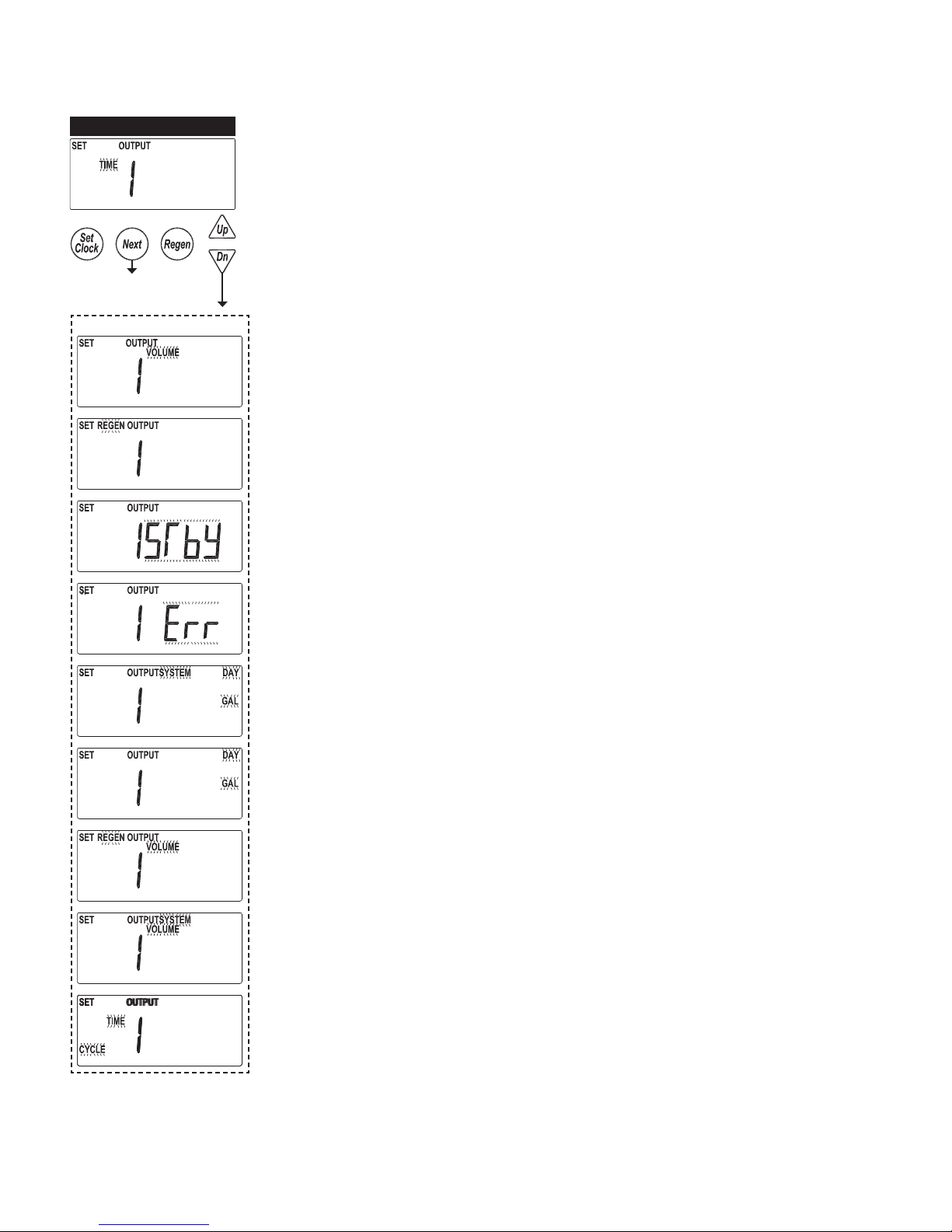
TYPICAL USER SCREENS
USER 1
USER 2
USER 2B
USER 1 - Capacity Remaining
• Displays the units current capacity remaining
• This screen does not display on units with volumetric capacity turned off
• Can be manually decremented by holding the down arrow
USER 2 - Days Remaining, Single Unit
• Displays a single units days until a regeneration, based on the day override setting
• This screen does not display on units with day override turned off
• On systems the master unit displays the days remaining on the lead unit
• Days can be manually reduced by holding the down arrow
USER 2B - Days Remaining, System
• The master in a system displays the days until a regeneration, based on the day override
settings.
• The displays also indicates which unit the day over ride is currently pertaining to
- Series regen systems do not display a unit as they will regenerate all units sequentially
USER 3
USER 4
USER 5
USER 3 - Time
• Displays the current time of day
USER 4 - Flow Rate, Unit
• Displays that units current ow rate
USER 5 - Volume Totalizer, Unit
• Displays the total volume since install / reset
• Re-settable to zero, while in this screen, by holding the “Set Clock” & “Regen” buttons

WS2H and WS3 Manual Page 15
TYPICAL USER SCREENS (CONTINUED)
USER 6
USER 7
USER 1
USER 6 – Flow Rate, System
• Displays the current combined ow rate of all the units in the system
• This screen does not display on single tank units, or systems with volumetric capacity turned
off
USER 7 – Volume Totalizer, System
• Displays the total volume of the system since install / reset
• Re-settable to zero, while in this screen, by holding the “Set Clock” & “Regen” buttons
• This screen does not display on single tank units

Page 16 WS2H and WS3 Manual
SETTING TIME OF DAY
SET TIME
Accessed by pressing Set Clock while in the User Screens. Use UP and DOWN
arrows to scroll hours. AM/PM alternates at midnight.
RETURN TO
NORMAL OPERATION
NOTIFICATIONS
• REGEN TODAY
- Flashing indicates a regeneration has been manually set and can be turned off
by pressing and releasing the REGEN button
- A solid display indicates the regeneration has been scheduled by input
requirements and can’t be manually turned off
• REGEN START / REGEN HOLD
- The display will ash “REGEN” or “REGEN HOLD”, depending on settings, to
indicate an external switch closure to the Aux. Input
• HIGH USAGE
- Screen ashes indicating setpoint was reached when using relay outputs to
signal high water usage. All LED lights ash and the relay with that setpoint
closes.
• Screen and the relay are re-set by pressing any button
• System operates as normal behind the indicator screen.
- Only active if Timer 2 or Timer 3 is set to “Day & Gal” or “Day & Gal & System”
ERRORS
• NUMBER OF UNITS ERROR
- The master unit of a system would ash an error screen alerting of a loss of
communication with a unit
- Check for proper operation and connectivity of the unit speci ed as lost
communications
- Pressing any button will return the user to the # units set up screen to correct /
verify the value of units in the system. Exiting will re-establish communications
- Each unit of the system will regenerate, based on its settings, with hard water
bypass
• FUNCTIONAL ERROR
- “Error” and its code alternate on the display
- The unit attempts to return to service but will not
regenerate until the error is cleared
- See troubleshooting section for a description of
possible error codes.

WS2H and WS3 Manual Page 17
SYSTEM SETUP SCREENS
Accessed by pressing NEXT and DOWN simultaneously for >3 seconds.
• System setup screens will be hidden on units determined to be a slaves of a system
- Slave units need to be reset, “Next” & “Regen”, from the Timer 1 screen to have their
slave status tuned off.
SYSTEM SETUP 1
SYSTEM SETUP 2A
SYSTEM SETUP 2B
Non-Default Settings
SYSTEM SETUP 1 – Select units of operation
US: Volume measurements are in gallons, time is displayed in 12 hour format, meter
selections are in inches.
SI: Volume measurements are in liters or cubic meters, time is displayed in 24 hour format,
meter selections are in mm.
SYSTEM SETUP 2A - Set number of units
1 – 2 Up to 2 units can be connected off the communicate port of the main board
3 – 4 Requires an optional system board to expand communication ports
SYSTEM SETUP 2B – Select System Type / Operation
• Setting a ow rate adder point determines the system operation
0: Parallel Flow; All units are always online unless they are regenerating.
• Units in a parallel ow system will determine the need to regenerate based on:
- Any one unit reaching 0 capacity
- Day over ride
• Any one units need to regenerate will initiate sequential regenerations of all units (series
regeneration)
• On0 systems will regenerate all units in series at the rst available time slot
• Delayed units will regenerate at each available time slot, one unit per time slot
ALT: Operates the system as an alternator, having one unit off line at all times either
regenerating or fully regenerated.
• A unit in an alternator system will determine the need to regenerate based on:
- The current “lead” unit reaching 0 capacity
• On0 systems immediately regenerate and alternate the exhausted unit with a fully
regenerated standby unit.
• Delayed systems will immediately alternate the exhausted unit with a fully regenerated
standby unit, and regenerate at the next available time slot.
- “Lead” unit regenerates based on “Lag” units
• The rst “lag” unit depleting down to 15% less than its ratio of system capacity
- 1/3 for a 4 unit; ½ for a 3 unit
- The second “lag” unit depleting down to 15% less than its ratio of system capacity
• 2/3 for a 4 unit
• Delayed systems will ag “lead” units based on “lag” capacity, but will not alternate
with remaining capacity until the next available delayed time.
- Day over ride
• 1 day; 1 unit will regen
• Day triggered regens will run at the time set in DEL-1
CONTINUED...

Page 18 WS2H and WS3 Manual
SYSTEM SETUP SCREENS (CONTINUED)
1 – 499: Demand Recall; one unit is always online & additional units are added as the
online units exceed this ow rate / unit set point.
• Additional units are brought online when:
- The adder point is exceeded for 30 seconds
- All required units required to cover the ow conditions will be brought into service
immediately if the ow exceeds 120% of the adder point.
• Units will go of ine when
- System ow reduces to 95% of the set adder point / unit for 1 minute.
• Any unit in a demand recall system will determine the need to regenerate based on:
- Each unit individually reaching 0 capacity
• On 0 systems will regenerate depleted units immediately after current ow conditions
allow depleted units of ine.
• Delayed units will alternate lead units immediately upon exhaustion & regenerate them
at the next available time slot.
- Day Override
• One unit will be regenerated per delayed time slot (i.e. a 4 unit system will need 4
delayed times to regenerate all units / set number of days).
• Day triggered regens will run at the time set in DEL-1
- Units cannot regenerate if ow demands them to remain online
• On 0 units regen immediately after ow allows them of ine
• Del units regen at the next available time slot
• Day units regen at the next time slot
SYSTEM SETUP 2C
SYSTEM SETUP 3A
Non-Default Settings
SYSTEM SETUP 2C – Set Pre-Service Rinse
- Only available on Alternator systems
- Standby units will run through a rinse cycle before coming into service
SYSTEM SETUP 3A - Select isolation timing
• Selections allow enabling and timing control of motorized drive
• Selection availability can vary by the type of system
• Custom timing sequences can be con gured under “Custom Motorized Drive Timing” at
the end of the programming section
HbP: Hardwater Bypass
• Only available on single units
• Unit will internally bypass hard water to the service lines while in regeneration
no.HbP: No Hardwater Bypass
• Each unit has isolation to control system operation and will not supply service water
during regeneration
• Drive timing will bring the unit into service during ll
SEP.In: Separate Source
• Each unit has isolation to control system operation and will not supply service water
during regeneration
• Drive timing will keep units isolated through the entire regeneration sequence
ALT-A: Simple Alternator Sharing 1 MAV
• Only available when set to a 2 unit alternator
• A “Simple 2 Unit” shares one MAV to be electrically connected to the bypass connection
of the “B” (slave) unit
WS2H and WS3 Manual Page 19
SYSTEM SETUP SCREENS (CONTINUED)
SYSTEM SETUP 3B
Non-Default Settings
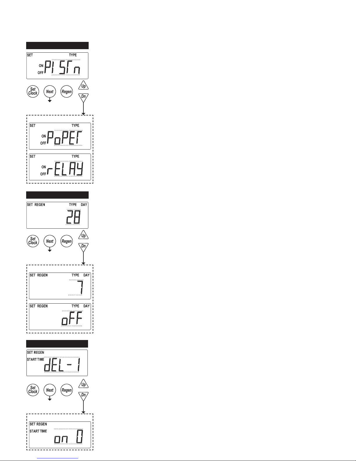
SYSTEM SETUP 3B - Select isolation type
• Piston: Factory motorized isolation drive has an internal piston & seals similar to the main
piston
• Poppet: Factory motorized isolation drive uses a at disc “face” seal
• Relay: Isolation will be done through the optional board relays & does not initialize the
BYPASS motorized drive circuit
SYSTEM SETUP 4
Non-Default Settings
SYSTEM SETUP 5
SYSTEM SETUP 4 - Day override control
• 28 day time clock: Used to regenerate units based on a set number of days between
regenerations
• 7 Day Time Clock: Used to control regeneration based on speci c days
• OFF: Days have no control on regenerations, and will not be a selection if volumetric
capacity is set to OFF
SYSTEM SETUP 5 - Regeneration control
Delayed 1 – 4
• Delays regeneration of units upon reaching 0 gallons capacity
• Allows setting of up to 4 regeneration times per day
• Systems with delayed regen will remove a unit from service based upon 0 capacity and
regenerate at the scheduled regen time.
- Only one unit will regen / scheduled time
• Day driven regens will regen at the DEL-1 time slot
• Depleted units will regen at the next available delayed time slot
Non-Default Settings
On 0
-Immediate regeneration of units upon reaching 0 capacity
-Series regeneration systems set to On0 will sequentially regenerate all units at the
delayed time based on day override

Page 20 WS2H and WS3 Manual
SYSTEM SETUP SCREENS (CONTINUED)
SYSTEM SETUP 6
SYSTEM SETUP 7A
Non-Default Settings
SYSTEM SETUP 6 – Automatic reserve calculation
This screen will not display on units set to On 0, capacity set to Off, or any systems
On: Unit will regenerate before reaching 0 capacity, based on previous usage trends
Requires delayed regeneration
OFF: Regeneration is scheduled after reaching 0 capacity
SYSTEM SETUP 7A - Auxiliary Input
START REGEN
• Control will start an immediate regeneration upon switch closure
• Systems follow “on0 logic” regenerating all agged units sequentially
START TIME REGEN dEL
• Control will immediately schedule a regeneration upon accumulating 2 minutes of
intermittent switch closures
• Systems follow “Delayed Logic” regenerating agged units in available time slots
START REGEN dEL
• Control will immediately schedule a regen upon switch closure
• Systems follow “Delayed Logic” regenerating agged units in available time slots
LEVEL
• Only available on single units
• External switching can be used to control the On Line / Standby status
- Switch closure will trigger the unit to go to a standby condition
HOLD
• Regeneration will not be allowed as long as there is switch closure
- On0 units will regenerate immediately after the hold switch opens
- Delayed regenerations will be delayed until the next scheduled time if the hold is active
when the scheduled time passes
START TIME REGEN
• Control will immediately regenerate upon accumulating 2 minutes of intermittent switch
closures
• Systems follow “on0 logic” regenerating all agged units sequentially
SYSTEM SETUP 7B
SYSTEM SETUP 7B - Level option selected
Set a time duration of switch closure when Level option is selected

WS2H and WS3 Manual Page 21
SYSTEM SETUP SCREENS (CONTINUED)
SYSTEM SETUP 8A
Non-Default Settings
SYSTEM SETUP 8A - Meter Calibration
2.0: Setting for using a factory 2” meter
3.0: Setting for using a factory 3” meter
Pulses: Used to set meter input off custom pulse rate, typically for non-factory meters
System Pulses: Only available on 2 unit alternators. The system shares 1 external meter
which is connected to the slave unit’s meter connection.
SYSTEM SETUP 8B
SYSTEM SETUP 9
SYSTEM SETUP 8B - Set Meter Pulses / Gallon
-Only displays if “Pulses” or “System Pulses” is selected in the previous screen
-Set to the desired pulse rate of the installed metering device
SYSTEM SETUP 9 – Auxiliary Drive
• Selections allow enabling and timing control of the Auxilliary
motorized drive circuit
- This screen does not display if the unit does not have a
system board
• Requires a factory motorized drive to be connected to the
drive circuit of the system board
• Custom timing sequences can be con gured under “Custom
Motorized Drive Timing” at the end of the programming
section
Non-Default Settings
no.HbP: No Hard Water Bypass
• Each unit has isolation to control system operation and will not
supply service water during regeneration
• Drive timing will bring the unit into service during ll
SEP.In: Separate Source
-Each unit has isolation to control system operation and will not
supply service water during regeneration
-Drive timing will keep units isolated through the entire
regeneration sequence
Page 22 WS2H and WS3 Manual
CYCLE SETUP SCREENS
Accessed by pressing NEXT and DOWN simultaneously for >3 seconds, then by pressing
NEXT and DOWN simultaneously again for >3 seconds, then by pressing NEXT and
DOWN simultaneously again for >3 seconds
CYCLE SETUP 1A
CYCLE SETUP 1B
CYCLE SETUP 1C
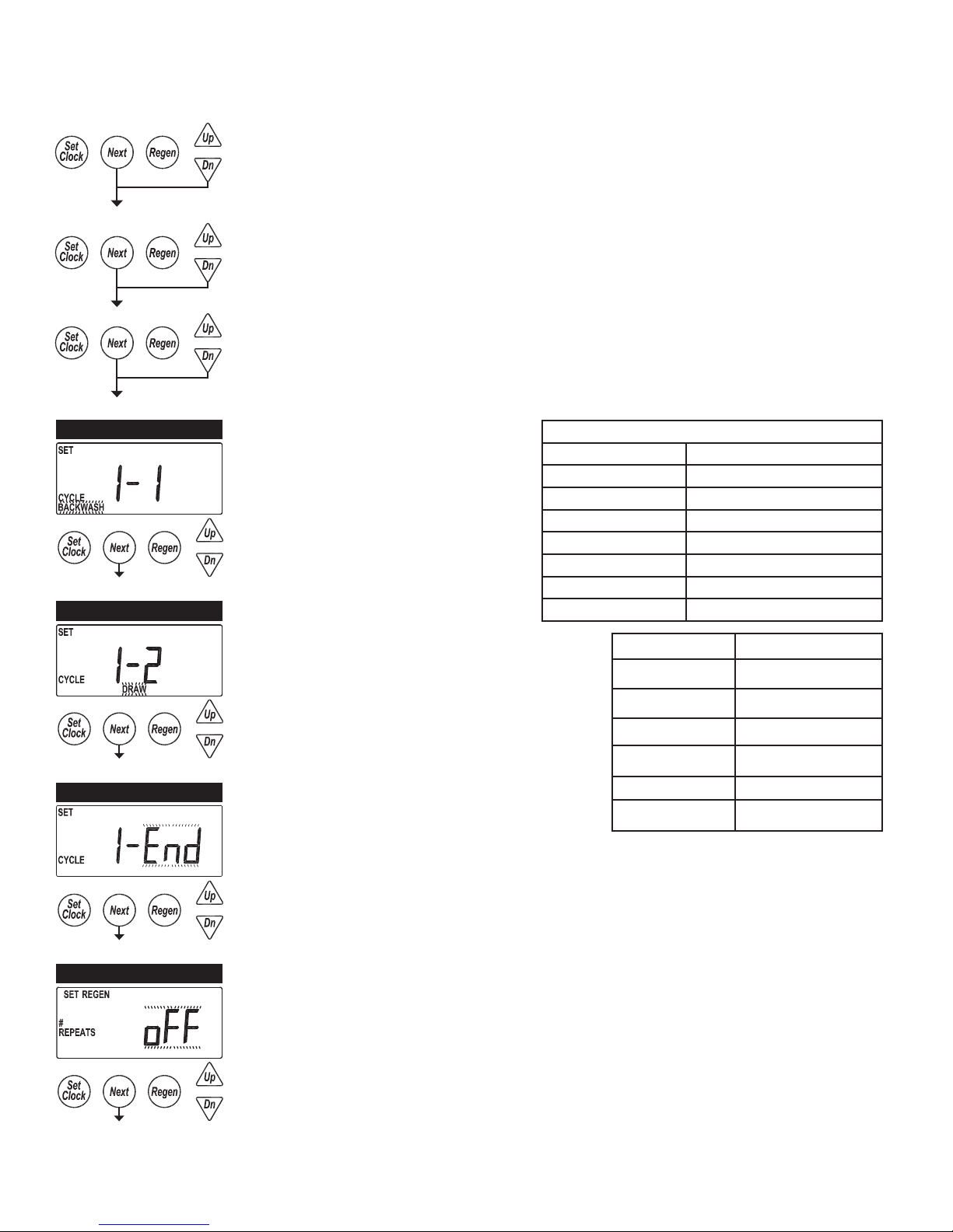
CYCLE SETUP 1A
Select rst regeneration cycle.
CYCLE SETUP 1B
Select second cycle.
CYCLE SETUP 1C
After cycles are con gured, an END is added.
(9 cycles maximum.)
Backwash
Draw
Slow Rinse Separate cycle from Draw
2nd Backwash
Rinse (fast)
Fill
End
Hold Piston in Service position
Available Cycles
Cycle Number Cycle Default
1 Backwash
2 Draw
3 2nd Backwash
4 Rinse
5 Fill
6 End
CYCLE SETUP 2
CYCLE SETUP 2
Select regeneration repeats, 1-9 or OFF.
Repeats regeneration cycle Sequence 1 a selected number of times before regenerating a
single time with Sequence 2.
The following screens will not appear if Cycle Setup 2 is set to OFF.
WS2H and WS3 Manual Page 23
CYCLE SETUP SCREENS (CONTINUED)
CYCLE SETUP 3A
CYCLE SETUP 3B
CYCLE SETUP 3C
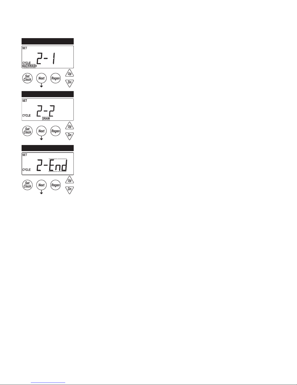
CYCLE SETUP 3A
Select rst cycle of “alternate” regeneration sequence (Sequence 2).
CYCLE SETUP 3B
Select second cycle of ‘alternate’ regeneration sequence.
CYCLE SETUP 3C
After cycles are con gured, an END is added. (9 cycles maximum.)
RETURN TO NORMAL
OPERATION
Page 24 WS2H and WS3 Manual
TIMER SCREENS
Accessed by pressing NEXT and DOWN simultaneously for >3 seconds, then by pressing
NEXT and DOWN simultaneously again for >3 seconds.
TIMER 1A
TIMER 1B
TIMER 1A2
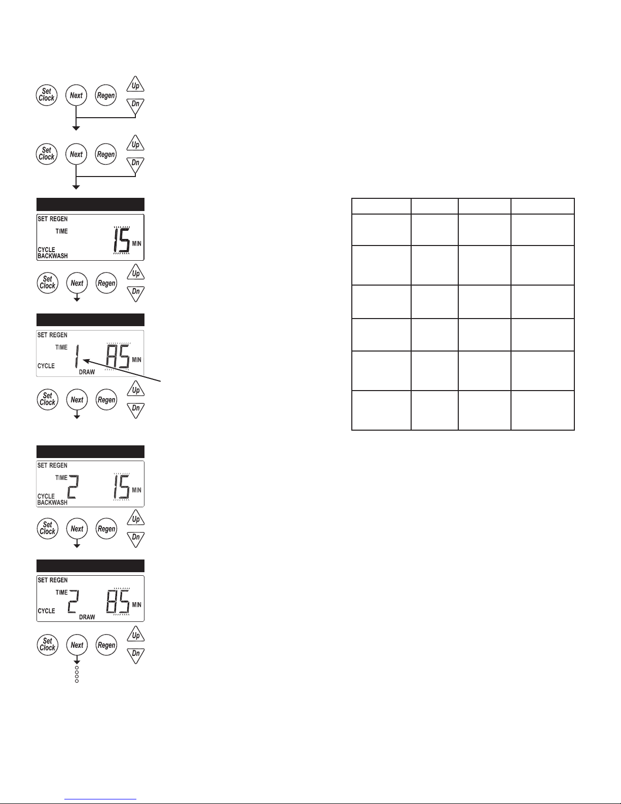
TIMER 1A
Select runtime of cycle 1.
TIMER 1B
Select runtime of cycle 2.
1 or 2 will be displayed if set for
Alternate Regenerations in Cycle
Setup 2.
TIMER 1A2
If Alternate Regenerations has been selected in Cycle Setup 2, select runtime of Alternate
Regeneration Cycle 1.
Cycle Units Range Increments
Backwash Minutes
Draw Minutes
Slow Rinse Minutes
Rinse Minutes
Fill Minutes
Hold Minutes
1-30
30-95
1-30
30-100
100-180
1-30
30-95
1-30
30-95
0.1-10.0
10.0-30.0
30.0-99.0
1-30
30-100
100-480
0.1
0.2
1.0
0.1
2.0
10.0
1
5
1
5
10
1
5
1
5
TIMER 1B2
TIMER 1B2
Select runtime of Alternate Regeneration, cycle 2.
WS2H and WS3 Manual Page 25
TIMER SCREENS (CONTINUED)
TIMER 2
Non-Default Settings
TIMER 2 – Set Trigger for Output 1
•Timer screens are only available with a system board installed
Time
•The relay is actuated based on a set amount of time after the start of regeneration
Volume
• The relay is actuated, during service only, every speci ed amount of volume usage
Regen
• Relay actuation is based on regen status
Standby
• Relay actuation is based on the units Standby status
• Relays would be used to control external valving or signaling a units Online status.
Error
• Relay actuates to signal an error condition
Day & Gal & System
• Relay actuates, based on system usage, at a speci ed daily volume to signal a usage
alarm.
• “Usage High” ashes on the screen with unit continues to operate as normal. Pressing
any button resets the relay and returns the unit to the user screens.
• Only available on the master unit of a system
Day & Gal
• Relay actuates, based on a units usage, at a speci ed daily volume to signal a usage
alarm
• “Usage High” ashes on the screen with unit continues to operate as normal. Pressing
any button resets the relay and returns the unit to the user screens.
Volume & Regen
• Relay is actuates, during service & while in regen, every speci ed amount of service
ow
Volume & System
• Relay actuates, at a speci ed amount, based on combined volume usage of all units in
the system
• Only available on the master unit of a system
Cycle
• Relay actuation is based on the start of a speci ed cycle

Page 26 WS2H and WS3 Manual
TIMER SCREENS (CONTINUED)
TIMER 3
TIMER 4
TIMER 5
TIMER 3 – Set Trigger for Output 2
• Trigger options are the same as for output 1
TIMER 4 – Set Output 1 Trigger
• Set the trigger point in these screens are based on the selection in the previous screens
TIMER 5 – Set the relays ON
time duration
• A unit’s ON time does not
accumulate; ie a unit set to
trigger the relay every 10
gallons and stay on for 5
minutes is owing 10 gpm.
The unit would not add 5
minutes every 10 gallons,
it would reset the 5 minute
countdown every 10 gallons
• A unit which is manually
stepped through regeneration
will reset the relay.
Trigger Units Range Increment Default
Time Min-
Cycle Slow
Volume Gal-
Volume Liters 5-750
Trigger Units Range Increment Default
Time Min-
Relay Trigger Settings
0-240 1 10
utes
1-200
lons
utes
200-1000
1000-
10000
750-4000
4000-
38000
Relay Duration Settings
:01-2:00
2:00-20:00
20-240
1
5
10
5
20
40
:01
:05
1
Rinse
20
75
3:00
TIMER 6
TIMER 6
Select Relay 2 output “ON”, per units previously selected.
Time
Time after the start of a regen before relay is actuated.
Cycle
Select a cycle which will actuate output 1.
Volume
Volume of water interval during service between relay actuations.

WS2H and WS3 Manual Page 27
TIMER SCREENS (CONTINUED)
TIMER 7
RETURN TO NORMAL
OPERATION
TIMER 7 – Set the relays ON time duration
• A unit’s ON time does not accumulate; ie a unit set to trigger the relay every 10 gallons
and stay on for 5 minutes is owing 10 gpm. The unit would not add 5 minutes every 10
gallons, it would reset the 5 minute countdown every 10 gallons
• A unit which is manually stepped through regeneration will reset the relay.

Page 28 WS2H and WS3 Manual
INSTALLER SETUP SCREENS
Accessed by pressing NEXT and UP simultaneously for >3 seconds.
INSTALLER 1
INSTALLER 2
INSTALLER 3
INSTALLER 1 – Set Volumetric Capacity
Capacity: Set the units Volumetric Capacity in
gallons or cubic meters
OFF
• Units will not regenerate based on volume
but will track usage history
• Will not be an option on units with no day
override set
Set current day and regen days when set
as a 7 day time clock in System Setup 1.
See next page.
INSTALLER 2 – Set Days Between Regenerations (Day override)
Set day override. 1-28 days between regenerations, or if set to 7 day time clock, see 7 day
setup on next page. OFF will only be displayed if “OFF” is selected in System Setup 4.
• Settings will be based on the type of day override control set in system setup.
• Off will be displayed for units with day override turned off
1 – 28: When set as a 28 day override
• Set the days between regens
1 – 7: When set as a 7 day timeclock
• First, set 1 – 7 to signify the current day (1 = Sunday – 7 = Saturday)
• Next turn regen on or off for each speci c day of the week, 1 - 7
INSTALLER 3 – Set Delayed Regeneration Time
• Set the delayed time of regeneration, hour (AM / PM toggles at midnight)
• Units with no time dependent control (Aux Input settings or Day Override) will display on0
X1000 Indicator Illuminates At 10,000
Gallons
Units
US
(GAL)
SI
(L)
10,000-100.00 x 1000
100.00-999.00 x 1000
50,000-50.00 x 1000
500.00-5000.0 x 1000
Range Increments
10-10,000
100
1000
50-50,000
5000
10
50
50
INSTALLER 4
INSTALLER 5
RETURN TO NORMAL
OPERATION
INSTALLER 4 – Set Delayed Regeneration Time
• Set delayed time of regeneration, minutes
INSTALLER 5 – Set Multiple Delayed Regeneration Times
• When con gured for multiple delayed regeneration times, repeat steps 3 & 4 for each
additional time slot

WS2H and WS3 Manual Page 29
INSTALLER SETUP SCREENS (CONTINUED)
7 DAY OPTION
INSTALLER 2A
INSTALLER 2A
7 day time clock option. Set current day of the week:
1 = Sunday
2 = Monday
3 = Tuesday
4 = Wednesday
5 = Thursday
6 = Friday
7 = Saturday
INSTALLER 2B
INSTALLER 2C
INSTALLER 3
(see previous page)
INSTALLER 2B
1 – 7: Signi es each day of the week, Sunday thru Saturday
• Scroll through each day using the up & down arrow
• Use Set Clock to toggle between ON or OFF to control regeneration for each day
- i.e., regen on Monday, no regen on Sunday
INSTALLER 2C
(i.e., no regeneration on Saturday.)

Page 30 WS2H and WS3 Manual
DIAGNOSTIC SCREENS
Accessed by pressing UP and DOWN simultaneously for >3 seconds.
DIAGNOSTIC 1
DIAGNOSTIC 2
DIAGNOSTIC 3
DIAGNOSTIC 1
Days since the last regeneration.
All Diagnostic History screens are resettable with the History Reset sequence while in the
Diagnostics 1 screen. Holding the Set Clock and Regen buttons for > 3 seconds initiates a
totalizer or history reset.
DIAGNOSTIC 2
Volume since the last regeneration.
DIAGNOSTIC 3
• Displays the reserve history
• Does not display on systems, or units with
AUTOMATICALLY
TOGGLES
Reserve Value
reserve set to OFF
• Use the UP & DN arrows to scroll through
each days history
- Day 0 is today’s reserve (tomorrows
anticipated usage)
- 1 was yesterday’s reserve (today’s
anticipated usage)
DIAGNOSTIC 4A
AUTOMATICALLY
TOGGLES
Simultaneously
press UP and
GO TO
DOWN.
DIAGNOSTIC 5A
GO TO
DIAGNOSTIC 4B
Gallons Used
DIAGNOSTIC 4A
History of volume used.
Use UP and DOWN arrows to select a day.
0 = Today
1 = Yesterday
63 = 63 days ago (max.)
REGEN will display if a regeneration occurred
that day.

WS2H and WS3 Manual Page 31
DIAGNOSTIC SCREENS (CONTINUED)
DIAGNOSTIC 4A
DIAGNOSTIC 5A
GO TO
DIAGNOSTIC 6
DIAGNOSTIC 4B
Hourly history of volume use. Use the UP and
DOWN arrow to select the hours of the day.
AUTOMATICALLY
TOGGLES
Volume used within the
selected hour
Returns user back to USE Day 0 in Diagnostic 4 screen.
DIAGNOSTICS 5A
• Displays the max ow rate and the hour it
occurred
AUTOMATICALLY
TOGGLES
Max ow rate of the day
• Use the UP & DN arrows to scroll through 28
days history
- Day 0 is today
- Day 1 was yesterday
Simultaneously
press UP and
DOWN.
DIAGNOSTIC 5B
DIAGNOSTIC 6
DIAGNOSTIC 7A
GO TO
DIAGNOSTIC 6
DIAGNOSTICS 5B
Hourly history of maximum ow rate. Use the
UP and DOWN arrow to select the hours of the
AUTOMATICALLY
TOGGLES
day from screen 5.
Max ow within the
selected hour
Returns user back to USE Day 0 in Diagnostic 5 screen.
DIAGNOSTIC 6
Total volume through the unit.
DIAGNOSTICS 7A
Total system history of volume used use UP and
DOWN arrows to select a day.
AUTOMATICALLY
TOGGLES
Max ow rate of the day
0 = Today
1 = Yesterday
63 = 63 days ago (max.)
Simultaneously
press UP and
DOWN.
GO TO
DIAGNOSTIC 7B

Page 32 WS2H and WS3 Manual
DIAGNOSTIC SCREENS (CONTINUED)
DIAGNOSTIC 7B
AUTOMATICALLY
TOGGLES
Volume used within the
selected hour
Returns user back to USE Day 0 in Diagnostic 7 screen.
DIAGNOSTIC 8
AUTOMATICALLY
TOGGLES
RETURN TO USER
SCREEN
DIAGNOSTICS 7B
Total system hourly history of volume use Up
and Down arrow to select the hours of the day
from Screen 7.

WS2H and WS3 Manual Page 33
THIS PAGE LEFT INTENTIONALLY BLANK

Page 34 WS2H and WS3 Manual
VALVE HISTORY
Accessed by pressing UP and DOWN simultaneously for >3 seconds,
then by pressing UP and DOWN simultaneously again for >3 seconds.
Non-Resettable
HISTORY 1
HISTORY 2
HISTORY 3
HISTORY 1
Total days since startup.
Time only accumulates while the unit is plugged in.
HISTORY 2
Total regenerations since startup.
HISTORY 3
Total volume treated since startup.
HISTORY 4
HISTORY 5
RETURN TO NORMAL
OPERATION
HISTORY 4
Main board software
HISTORY 5
System board software revision. Will display -nA- if no system board is detected.

WS2H and WS3 Manual Page 35
CUSTOM MOTORIZED DRIVE TIMING
• Used to alter the standard timing sequence of the motorized isolation valve for
complete custom timing of the drive circuits
- Setup procedure applies to both the “Bypass” drive of the main board and “Aux
Drive” of the optional expansion board
• Customization needs to be done after de ning the regeneration cycle sequence
• Accessed by pressing the Up & Dn arrows simultaneously while in the No Hard
Water Bypass selection
- Next will scroll through each cycle of the regeneration program
- Arrow buttons toggle Standby and Online indicating the desired position the
drive during that cycle of the regeneration.
- In the example screens the “Bypass” drive will be transitioning of ine for
Backwash (Cycle 1) and coming online for Fill (Cycle 5).
• Timing can be further customized per cycle by adding a time delay to the
sequence
- Accessed by pressing the Up & Dn arrows simultaneously while in the drive
sequence screens
- Setting a “Start Time” delays the start of that transition after reaching set cycle
- A second time screen then sets the time the drive maintains that set position
before transition back to its previous position.
- “Regen” will be illuminated to identify that a sequence has a time modi er
associated with it
- In the example screens the “Bypass” drive will delay its transition to of ine until 2
minutes into Backwash (Cycle 1) and coming online for Fill (Cycle 5).
Page 36 WS2H and WS3 Manual
INSTALLATION
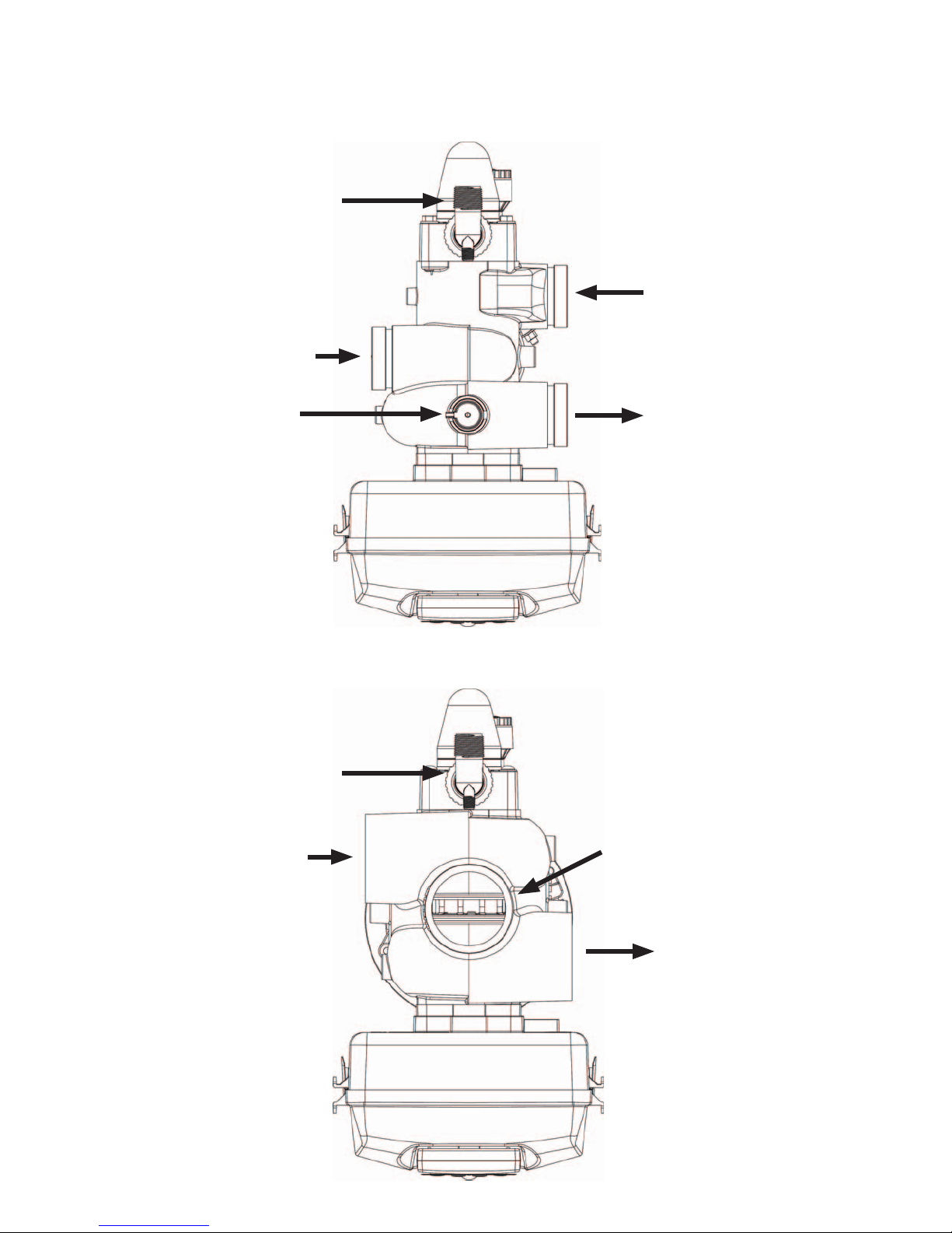
WS2H CONTROL VALVE TOP VIEW
BRINE/REFILL
INLET
DRAIN
INTERNAL
FLOW METER
BRINE/REFILL
INLET
OUTLET
WS3 CONTROL VALVE TOP VIEW
DRAIN
OUTLET

WS2H and WS3 Manual Page 37
INSTALLATION (CONTINUED)
GENERAL INSTALLATION & SERVICE WARNINGS
The control valve and ttings are not designed to support the weight of the system or the plumbing.
Do not use Vaseline, oils, other hydrocarbon lubricants or spray silicone anywhere. A silicone lubricant may be used on
black o-rings but is not necessary.
HYDROCARBONS SUCH AS KEROSENE, BENZENE, GASOLINE, ETC., MAY DAMAGE PRODUCTS THAT
CONTAIN O-RINGS OR PLASTIC COMPONENTS. EXPOSURE TO SUCH HYDROCARBONS MAY CAUSE THE
PRODUCTS TO LEAK. DO NOT USE THE PRODUCT(S) CONTAINED IN THIS DOCUMENT ON WATER SUPPLIES
THAT CONTAIN HYDROCARBONS SUCH AS KEROSENE, BENZENE, GASOLINE, ETC.
THIS WATER METER SHOULD NOT BE USED AS THE PRIMARY MONITORING DEVICE FOR CRITICAL OR
HEALTH EFFECT APPLICATIONS
Do not use pipe dope or other sealants on threads. Te on tape is recommended to be used on all threads.
Use of pipe dope may break down the plastics in the control valve.
When servicing the valve, water may leak
from the valve. Water from the valve may
create a slip hazard. Clean up water spills.
Allow two feet of clearance to service WS2H and WS3 valves.
The valve will withstand transportation and storage temperatures of -13 ˚F (-25 ˚C) to 131 ˚F (55 ˚C) and for short
periods up to 158 ˚F (70 ˚C). If valve has been exposed to freezing conditions let valve warm up to room temperature
before running water through it. The valve has been packaged to prevent damage from the effects of normal humidity,
vibration and shock.
SITE REQUIREMENTS:
• The plug-in Power adapter is for dry locations only
• The tanks should be on a rm, level surface
• Electrical: Use an uninterrupted outlet installed within 15 feet (4.57 meters) of the water conditioner.
All plumbing should be done in accordance with local codes.
1. Locate the water conditioner so the distance between the drain and the water conditioner is as short as possible.
2. Regenerant tanks that must be re lled should be located where they are easily accessible. It is recommended a
safety brine valve be used.
3. Do not install any water conditioner with less than 10 feet of piping between its outlet and the inlet of a water heater.
Disconnect from electrical power
prior to servicing the valve.
4. Do not locate unit where it or its connections (including the drain and over ow lines) will ever be subjected to room
temperatures under 40° F (4° C).
5. The use of resin cleaners in a non-vented enclosure is not recommended.

Page 38 WS2H and WS3 Manual
INSTALLATION (CONTINUED)
6. INLET/OUTLET PLUMBING: Connect to a supply line downstream of outdoor spigots. Install inlet and outlet
shutoff valves for the control valve; see top view drawings for control valve inlet and outlet locations. Installation of a
three valve bypass is recommended. If using plastic ttings ground the water conditioner per local electric codes. If an
external water meter is used, install the water meter on the outlet side of the control valve. It is recommended that the
meter assembly be installed horizontally or in a down ow vertical position to reduce turbine bearing wear. The turbine
assembly may be orientated in any direction. Remove the cover and drive bracket and thread the water meter cord
through the hole in the back plate. Reinstall the drive bracket. Weave the cord through the strain relief on the backplate
and connect the end to the three prong connector labeled FLOW on the printed circuit board. Re-install the cover.
7. Drain: Verify that the drain can handle the backwash rate of the water conditioner. Correctly size the drain line
and install an appropriately sized drain line ow control. For WS2H and WS3 valves a drain line ow control are
NOT supplied with a valve. For WS2H valves the drain outlet is 2” Female NPT or BSPT threads or 2.5” groove lock
connection. For WS3 valves the drain port is 3” Female NPT or BSPT, no groove lock connection. If using copper,
solder joints near the drain must be done prior to connecting the drain line ow control tting. Leave at least 6” (152.4
mm) between the drain line ow control tting and solder joints to prevent heat from damaging the ow control.
Avoid elevating the drain line above the control valve where possible. Discharge the drain line through an air gap to a
receptacle in accordance with local plumbing codes.
IMPORTANT: Never insert a drain line directly into a drain, sewer line, or trap. Always allow an air gap between
the drain line and the receptacle to prevent back siphonage.
8. Regeneration: If the control valve is to be used to regenerate the water conditioner with brine (saturated salt
solution) or other regenerants. The WS2H and WS3 control valves regenerant port has a 1” 90° Male NPT threaded
outlet connection that swivels 360°. To ensure acceptable operation of the injectors use 1” pipe to connect to the brine
tank. Smaller drain line ow controls may result in the injector performance not matching the injector graphs. Use an
adequately size drain line ow control to ensure proper brine draw.
See Table 3 for injector order number and size for tank diameter. An over ow drain line from the regenerant tank that
discharges into an acceptable drain is recommended, as a regenerant over ow could damage furnishings or the
building structure. Connect a line to the over ow tting on the regenerant tank. If an over ow tting is not already
installed on the regenerant tank, install one. Do not elevate the over ow drain line. Discharge the over ow drain line
through an air gap to a receptacle in accordance with local plumbing codes.
9. Power Adapter: If a Power Adapter is already connected to the control valve, plug the Power Adapter into an
uninterrupted outlet. If the Power Adapter cord has not yet been connected to the control valve, remove the control
valve cover and the drive bracket and thread Power Adapter cord through the hole in the back plate. Reinstall the drive
bracket. Weave the cord through the strain relief on the backplate and connect the end to the four pin connector on
the printed circuit board labeled POWER. Reinstall the cover. Plug the Power Adapter into an uninterrupted outlet.
10. Program the control valve: It is very important to program the control valve for the type of system (e.g. water
softener of lter) and the end use application. Check the program used prior to testing the system.

WS2H and WS3 Manual Page 39
INSTALLATION SUMMARY
Installation Date: ___________________________________________
Installation Location: _______________________________________
Installer(s): ________________________________________________
Phone Number:
Application Type: (Softener) __________Other: _____________
Water Source: ____________________________________________
Water Test Results:
Hardness: ______________Iron: _______________pH: ___________
Other: ____________________________________________________
__________________________________________________________
Misc:
Service Flow Rates: min. ______________ max. ______________
Tank Size: Diameter ______________ Height: __________________
Resin or Media Volume: ____________________________________
Resin or Media Type: _______________________________________
Capacity: _________________________________________________
Salt or Fill Setting per Regeneration: _________________________
Brine Tank Size: ___________________________________________
Control Valve Con guration:
Valve Type:________________________________________________
Valve Part Number: ________________________________________
Valve Serial Number: _______________________________________
Regenerant Re ll Control: _________________________ gpm/lpm
Injector Size: ______________________________________________
Drain Line Flow Control: __________________________ gpm/lpm

Page 40 WS2H and WS3 Manual
CYCLE POSITIONS / FLOW DIAGRAMS
SERVICE
Raw Water
Treated Water Outlet
Inlet
Raw/Hard Water is bypassed
during regeneration
BACKWASH
Backwash Water
to Drain
Raw Water
Inlet

WS2H and WS3 Manual Page 41
CYCLE POSITIONS / FLOW DIAGRAMS (CONTINUED)
DRAW
Backwash Water
to Drain
Raw/Hard Water is bypassed
during regeneration
Raw Water
Inlet
Regenerant
solution being
drawn in
Injector feed
water from
Raw Water Inlet
supply
Raw/Hard Water is bypassed
during regeneration
SLOW RINSE
Slow Rinse Water
to Drain
Raw Water
Inlet
Injector feed
water from
Raw Water Inlet
supply

Page 42 WS2H and WS3 Manual
CYCLE POSITIONS / FLOW DIAGRAMS (CONTINUED)
RINSE
Rinse Water to
Drain
Raw/Hard Water is bypassed
during regeneration
Raw Water
Inlet
Treated Water Supply
Re ll port to re ll
tube for treated water
SOFT WATER REFILL
Raw Water
Inlet
Treated Water to
Regenerant Tank
Treated water
from Re ll Tube

WS2H and WS3 Manual Page 43
FRONT COVER AND DRIVE ASSEMBLY
Drawing No. Order No. Description Quantity
1 V3068 WS2H/3 POD FRNT-BK COVERS 1
1a V3082 WS2H/3 POD ASY COMPLETE W/BOARD* Optional
2 V3241-01 BOARD WS2H/3 PC BOARD DISPLAY 1
3 V3248 WS2H/3 CABLE DISPLAY POD 1
1
4 V3242-01BOARD WS2H/3 PC BOARD VALVE
5 V3224-01R WS2H/3 COVER ASY PLATINUM 1
6 V3107-01 WS1 MOTOR ASY 1
7 V3226-01 WS2H/3 DRIVE BRACKET ASY 1
8 V3110 WS1 DRIVE GEAR 12X36 3
9 V3109 WS1 DRIVE GEAR COVER 1
V3461-01 WS2H/3 AC ADAPTER 18VAC 1
Not Shown
V3461EU-01 WS2H/3 AC ADAPTER EU 18VAC
V3461UK-01 WS2H/3 AC ADAPTER UK 18VAC
10 V3243-01BOARD WS2H/3 PC BOARD SYSTEM
Not Shown V3475-12 WS2H/3 SYS CONNECT CORD 12 FT RED Optional
Not Shown V3475-24 WS2H/3 SYS CONNECT CORD 24 FT BL Optional
Not Shown V3475-36 WS2H/3 SYS CONNECT CORD 36 FT YEL Optional
See Table 2 Software and
Power Supply Compatibility
for option Selection
See Table 2 Software and Power
Supply Compatibility for option
selection
1
See Table 2 Software and
Power Supply Compatibility
for option Selection
*Contains items 1,2 & 3 Pod Assembly, PC Board and Cable
1a
1
2
3
5
7
9
8
4
6
10

Page 44 WS2H and WS3 Manual
WS2H DRIVE CAP ASSEMBLY, DOWNFLOW PISTON, REGENERANT PISTON, SPACER
STACK ASSEMBLY, DRIVE BACK PLATE, MAIN BODY AND METER
Drawing No. Order No. Description Quantity
1 V3275 WS2H/3 SCW BSHD SS3/8-16X2-1/4 (7/32” hex allen wrench required) 4
2 V3291 WS2H/3 WASHER SS 3/8 4
3 V3225 WS2H/3 BACK PLATE 1
4 V3066 WS2H DRIVE ASY 1
5 V3289 O-RING 344 1
6 V3204-01 WS2H PISTON 1
7 V3238-01*** WS2H/3 BRINE PISTON 1
8 V3065 WS2H STACK ASY 1
Not Shown
9
10 V3632* WS1.5/2/3 METER RETAINING CLIP 1
11 V3003-02 WS1.5/2H METER COMMERCIAL ASY 1
12 V3118-03 WS1.5/2 TURBINE ASY 1
13 V3105 O-RING 215 1
14 V3501 WS1.5/2 TURBINE CLIP 1
15 V3279 O-RING 346 1
16
17 V3054** WS2H 4 IN BASE CLAMP ASY 1
18 V3276 WS2H/3 BOLT HEX SS 5/16-18X1-3/4 1
19 V3269 WS2H/3 NUT 5/16-18 SS HEX 1
Not Shown D1300-01 TOP BAFFLE DFSR CLACK 2/63MM 1
* In 2008 a modi cation was made to Meter Housings to use V3632 WS1.5/2/3 Meter Retaining Clip. Do not use V3632 on old style
housings which have holes through the castings to accept the U-shaped V3223 WS2 Meter Clip.
**V3054 WS2 4 IN BASE CLAMP ASY includes a V3276 WS2 BOLT HEX SS 5/16-18X1-3/4 and V3269 WS2 NUT 5/16-18 SS HEX.
***V3238-01 Brine Piston is used for Backwash Only valves.
THIS WATER METER SHOULD NOT BE USED AS THE PRIMARY MONITORING DEVICE FOR CRITICAL OR HEALTH EFFECT APPLICATIONS.
Service or replace the turbine by:
1. Turn the bypass for the system off and relieve the pressure on the system.
2. Press downward on the remote meter assembly to relieve tension on the retaining clip V3632 (or the U-shaped V3223 WS2 Meter Clip). Remove
the clip and take the meter assembly out of the housing.
3. Remove the bend from the two exposed tips of the retaining clip V3501 and remove clip.
4. Service or replace the V3118-03 WS15/2 Turbine Assembly and place it back in the turbine shaft.
5. Insert the V3501 WS15/2 Turbine Clip and re-bend the exposed ends of the clip. The V3118-03 turbine has a groove to line up with the V3501
WS15/2 Turbine Clip.
6. Insert meter assembly back into the meter housing.
7. Re-install the meter retaining clip V3632 as shown below (or the U-shaped V3223 WS2 Meter Clip).
8. Open the bypass for the system slowly to bring back into service and check to be sure you have no water leaks.
V3468-04 WS15/2/3 PLUG 1/4NPT PLST TAPE
V3465-04 WS15/2/3 PLG 1/4BSPT PLST TAPE
V3201-03 WS15/2/3 PLG 1/4BSPT PLST TAPE
V3201BSPT-03 WS2H BSPT BODY W/V3465 PLUG
V3280 O-RING 332 FOR VALVE BODIES WITH NPT THREADS
V3452 O-RING 230 FOR VALVE BODIES WITH BSPT THREADS
2
1
1
Typical meter retaining clip
installation. Ensure clip is fully
engaged in groove and tabs
positioned in slot as shown.
3
2
4
1
Install D1300-01 upper diffuser (not shown) when using the 4” Quick Disconnect (V3064)
10
11
B or indent
indicates BSPT
N or no mark
indicates NPT
5
6
7
8
12
13
14
9
15
16
17
18
19

WS2H and WS3 Manual Page 45
WS3 DRIVE CAP ASSEMBLY, DOWNFLOW PISTON, REGENERANT PISTON, SPACER STACK
ASSEMBLY, DRIVE BACK PLATE AND MAIN BODY
Drawing No. Order No. Description Quantity
1 V3275 WS2H/3 SCW BSHD SS3/8-16X2-1/4 (7/32” hex allen wrench required) 4
2 V3291 WS2H/3 WASHER SS 3/8 4
3 V3225 WS2H/3 BACK PLATE 1
4 V3093 WS3 DRIVE ASY 1
5 V3289 O-RING 344 1
6 V3666-01 WS3 PISTON 1
7 V3238-01** WS2H/3 BRINE PISTON 1
8 V3092 WS3 STACK ASY 1
Not Shown
9
10 V3763 O-RING 361 1
11 V3762 O-RING 341 FOR VALVE BODIES WITH NPT OR BSPT THREADS 1
12 V3091* WS3 BASE CLAMP ASY 1
13 V3276 WS2H/3 BOLT HEX SS 5/16-18X1-3/4 1
14 V3269 WS2H/3 NUT 5/16-18 SS HEX 1
Not Shown V3672 TOP BAFFLE DFSR CLACK 3/90MM 1
*V3091 WS3 BASE CLAMP ASY includes a V3276 WS2H/3 BOLT HEX SS 5/16-18X1-3/4 and V3269 WS2H/3 NUT 5/16-18 SS HEX.
**V3238-01 Brine Piston is used for Backwash Only valves.
V3468-04 WS15/2/3 PLUG 1/4NPT PLST TAPE
V3465-04 WS15/2/3 PLG 1/4BSPT PLST TAPE
V3667-03 WS3 BODY W/V3468 PLUG
V3667BSPT-03 WS3 BSPT BODY W/V3465 PLUG
2
1
B Indicates BSPT
N Indicates NPT
9
3
4
2
5
6
7
8
1
10
11
14
Install V3672 upper diffuser (not shown) when using the 6” Flange Base (V3090)
12
13

Page 46 WS2H and WS3 Manual
WS2H AND WS3 BRINE VALVE BODY AND INJECTOR COMPONENTS
Drawing No. Order No. Description
1 V3237-01 WS2H/3 SOFTFILL TUBE ASY 1 1
2a V3236-04* WS2H INJECTOR TUBE ASY FOR A THRU H 1
2b V3670-01** WS3 INJECTOR TUBE DOWNFLOW ASY 1
3 V3289 O-RING 344 1 1
4 V3067 WS2H/3 BRINE BODY ASY 1 1
5 V3477 WS2H/3 INJECTOR CAP 1 1
6 V3152 O-RING 135 1 1
7 V3275 WS2H/3 SCREW BSHD SS 3/8-16X2-1/4 (7/32” hex allen wrench required) 4 4
8 V3291 WS2H/3 WASHER SS 3/8 4 4
9 V3162-022*** WS1 DLFC 022 FOR 3/4 1 1
10 V3231 WS2H/3 REFILL FLOW CNTRL RETAINER 1 1
11 V3277 O-RING 211 1 1
12 V3105 O-RING 215 1 1
13 V3150 WS1 SPLIT RING 1 1
14 V3151 WS1 NUT 1 QC 1 1
15 V3149 WS1 FTG 1 MALE NPT ELBOW 1 1
Not Shown V3189 WS1 FTG 3/4&1 PVC SLVNT 90 Optional Optional
Not Shown V3499***** WS2H/3 FITTING CAP 1 IN THREADED 1 1
Not Shown V3797****** WS1 FTG 1 MALE BSPT ELBOW BSPT Only BSPT Only
*V3236-04 WS2H INJECTOR TUBE ASY A thru H contains a V3285 O-RING 213 and a V3286 O-RING 216.
**V3670-01 WS3 INJECTOR TUBE DOWNFLOW ASY contains a V3285 O-RING 213, V3286 O-RING 216 and a V3163 O-RING 019.
***Any V3162-XXX ow control may be used. V3237-01 WS2H SOFTFILL TUBE ASY contains a V3155 O-RING 112, V3287 O-RING 110 and a V3288 O-RING 206.
****V3010-2A through V3010-2G injectors contain a V3283 O-RING 117 and a V3284 O-RING 114. V3010-2H injectors use a V3283 O-RING 117 and D1263 O-RING 116.
Backwash Only Valves include a V3499 but do not include the following parts: V3189, V3162-022, V3231 and V3277.
***** Install V3499 on V3149 if valve is to be set up as a backwash only valve.
****** BSPT valves also include a V3797 WS1 FTG 1 MALE BSPT ELBOW
15
WS2H AND WS3 VALVE INJECTOR
ORDER INFORMATION
Injector Order
Number
Typical Tank
Diameter
1
Proper RFC orientation
directs re ll water ow
towards the washer face
with radius and text.
V3010-2A 18”
V3010-2B 21”
14
V3010-2C 24”
V3010-2D 30”
13
V3010-2E 36”
V3010-2F 42”
V3010-2G 48”
V3010-2H 63”
1
Actual injector size used may
vary depending on the design and
WATER
FLOW
12
11
10
8
9
application of the system. Injectors in
table are sized for a typical down ow
softener using standard mesh synthetic
cation exchange media regenerating
with sodium chloride.
3
Quantity
WS2H WS3
Backwash Only
V3499 Cap
installed
from factory
7
5
1
2A
2B
16
6
4

WS2H and WS3 Manual Page 47
STANDARD INJECTOR GRAPHS
Order No. V3010-2A
4
3
2
Flow Rate (gpm)
1
0
20 40 60 80 100 120
US Units
Total
Slow Rinse
Draw
Pressure (psi)
Order No. V3010-2C
US Units
7
6
5
4
3
2
Flow Rate (gpm)
1
0
20 40 60 80 100 120
Total
Slow Rinse
Draw
Pressure (psi)
Order No. V3010-2B
6
5
4
3
2
Flow Rate (gpm)
1
0
20 40 60 80 100 120
US Units
Total
Slow Rinse
Draw
Pressure (psi)
Order No. V3010-2D
US Units
12
10
8
6
4
Flow Rate (gpm)
2
0
20 40 60 80 100 120
Total
Slow Rinse
Draw
Pressure (psi)
Order No. V3010-2E
16
14
12
10
8
6
Flow Rate (gpm)
4
2
0
20 40 60 80 100 120
US Units
Pressure (psi)
Order No. V3010-2G
US Units
24
22
20
18
16
14
12
10
8
Flow Rate (gpm)
6
4
2
0
20 40 60 80 100 120
Pressure (psi)
Total
Slow Rinse
Total
Slow Rinse
Order No. V3010-2F
US Units
18
16
14
12
10
Draw
8
6
Flow Rate (gpm)
4
2
0
20 40 60 80 100 120
Total
Slow Rinse
Draw
Pressure (psi)
Order No. V3010-2H
US Units
44
40
36
32
28
24
20
Draw
16
Flow Rate (gpm)
12
8
4
0
20 40 60 80
Total
Slow Rinse
Draw
100 120
Pressure (psi)

Page 48 WS2H and WS3 Manual
STANDARD INJECTOR GRAPHS (CONTINUED)
Order No. V3010-2A
Metric Units
16
14
12
10
8
6
Flow Rate (lpm)
4
2
0
100 200 300 400 500 600 700 800 900
Pressure (kPa)
Order No. V3010-2C
27
24
21
18
15
12
9
Flow Rate (lpm)
6
3
0
100 200 300 400 500 600 700 800 900
Metric Units
Total
Pressure (kPa)
Order No. V3010-2E
Metric Units
60
50
40
30
20
Flow Rate (lpm)
10
0
100 200 300 400 500 600 700 800 900
Total
Slow Rinse
Pressure (kPa)
Order No. V3010-2G
Metric Units
90
80
70
60
50
40
30
Flow Rate (lpm)
20
10
0
100 200 300 400 500 600 700 800 900
Slow Rinse
Pressure (kPa)
Total
Draw
Slow Rinse
Draw
Draw
Total
Draw
Slow Rinse
Order No. V3010-2B
21
18
15
12
9
Flow Rate (lpm)
6
3
0
100 200 300 400 500 600 700 800 900
Metric Units
Total
Slow Rinse
Draw
Pressure (kPa)
Order No. V3010-2D
Metric Units
40
35
30
25
20
15
Flow Rate (lpm)
10
5
0
100 200 300 400 500 600 700 800 900
Total
Slow Rinse
Draw
Pressure (kPa)
Order No. V3010-2F
Metric Units
70
60
50
40
30
Flow Rate (lpm)
20
10
0
100 200 300 400 500 600 700 800 900
Total
Slow Rinse
Draw
Pressure (kPa)
Order No. V3010-2H
Metric Units
160
140
120
100
80
60
Flow Rate (lpm)
40
20
0
100 200 300 400 500 600 700 800 900
Total
Slow Rinse
Draw
Pressure (kPa)
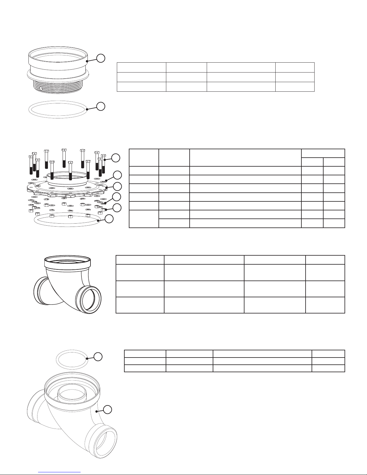
WS2H and WS3 Manual Page 49
V3064 WS2H/2QC 4 INCH BASE ASY (FOR USE ON WS2H OR WS2QC ONLY)
1
Drawing No. Order No. Description Quantity
1 V3202-01 WS2H BASE 1
2 V3419 O-RING 347 1
2
V3055 WS2H/2QC 6 INCH FLANGE BASE ASY or V3090 WS3 6 INCH FLANGE BASE ASY
2
6
3
4
Drawing
No.
1 V3444 WS2H SCREW HEXCAP 5/16-18X2 SS 12 12
2 V3293 WS2H WASHER SS 5/16 FLAT 24 24
3 V3445 WS2H WASHER SPLIT LOCK 5/16 SS 12 12
4 V3447 NUT HEX 5/16-18 SILICON BRASS 12 12
5 COR60FL O RING 6 FLANGE ADAPTER 1 1
6
1
5
Order
No.
V3261-01 WS2H FLANGE BASE 1
V3671-01 WS3 FLANGE BASE 1
Description
WS2H/2QC SIDE MOUNT BASE ASSEMBLY
Order No. Description Inlet/Outlet For Valve
V3260-02 WS2H/2QC SIDE MOUNT
NPT ASY
V3674-02 WS3 SIDE MOUNT
NPT ASY
V3674BSPT-02 WS3 SIDE MOUNT
BSPT ASY
Quantity
V3055 V3090
2” Female NPT or
2.5” Groove Lock
3” Female NPT WS3 NPT
3” Female BSPT WS3 BSPT
WS2H NPT
V3260BSPT-02 WS2H/2QC SIDE MOUNT BASE BSPT ASSEMBLY
1
2
Drawing No. Order No. Description Quantity
1 V3280 O-RING 332 1
2 V3260BSPT-01 WS2H SIDE MOUNT BASE BSPT 1
When using a side mount base with 2H or 2QC BSPT valves replace distributor
pilot o-ring V3452 O-RING 230 with V3280 O-RING 332. See exploded view of 2H
or 2QC valve for speci c location of distributor pilot o-ring.

Page 50 WS2H and WS3 Manual
DRAIN LINE FLOW CONTROLS
All drain line ow control housings are shipped without ow control washers.
See drain line ow control washer section for available ow selections.
PVC Elbow, 0.7 - 10 GPM
Inline Plastic, 9 - 25 GPM
Item Part# Description Qty.
V3158-04 WS Drain Fitting, 3/4” Elbow
1 V3158-03 Drain Elbow, 3/4 NPT 1
2 V3159-01 DLFC Retainer Assembly 1
3 V3163 O-ring, -019 1
4 H4615 Locking Clip 1
5* V3983 WS2 DLFC Adapter 1
6 V3162-xx See DLFC Section 1
*Also available: V3414 WS1.5 DLFC Adapter
1
Direction of Flow
3
2
6
5*
4
Item Part# Description Qty.
V3008-05 WS Drain Fitting, 1” Straight
1 V3167 WS Drain Fitting Adapter, 1” NPT 1
2 V3166-01 Drain Fitting Body 1
3 V3151 WS1 Nut, QC 1
4 V3150 WS1 Split Ring 1
5 V3105 O-ring -215 1
6 V3163 O-ring -019 1
7 H4615 Locking Clip 1
8** V3983 WS2 DLFC Adapter 1
9 V3190-xx See DLFC Section 1
**Also available: V3414 WS1.5 DLFC Adapter
1
Direction of Flow
3
4
2
5
1
8**
7
Drawing
No.
Order
No.
1 V3081 WS15 RETAINER DLFC ASY 1111
2
V3645 WS15 DLFC FLANGE OUTLET FNPT 1 1
V3645BSPT WS15 DLFC FLANGE OUTLET FBSPT 1 1
3 V3646 WS15 DLFC FLANGE INLET MNPT 1 1
4 V3388 WS125 DLFC FLANGE INLET MNPT 1 1
5 V3652 B S 5/16-18x3/4 4444
6 V3441 O-RING 226 1111
7 V3162-xx See DLFC Table 0-6 0-6 0-6 0-6
8 V3190-xx See DLFC Table 1111
4
Stainless Steel, 9 - 85 GPM
Description
Direction of Flow
6
1
3
DLFC not
supplied.
At least one
V3190-XXX
must be
installed in
center hole.
Quantity
V3079 V3079BSPT V3080 V3080BSPT
B indictates
BSPT
N indicates
2
NPT
5
Plugs may be
knocked out
or drilled to
use up to six
V3162-XXX.
WS2H and WS3 Manual Page 51
M X F STAINLESS STEEL, 0.7 – 150 GPM
Drawing
No.
1 V3052 WS2 DLFC Retainer Asy 1 1
2
3
4 V3273 Bolt Hex Hd S/S HCS 3/8-16x3/4 4 4
5 V3278 O-ring 338 1 1
6 V3162-XX See DLFC table 0-5 0-5
7 V3190-XX See DLFC table 0-4 0-4
Assemblies are shipped without drain line ow control (DLFC). Assembly instructions:
1. Determine the desired owrate. Select a combination of V3162-XXX’s and V3190-XXX’s to arrive at the
desired ow rate. Up to ve of the smaller V3162-XXX’s may be used. Up to four of the larger V3190-XXX’s
may be used.
2. Using a drill or punch remove the desired knockout(s) in V3052.
3. Smooth hole(s).
4. Install appropriate size(s) of drain line ow control washers. Pay close attention to proper DLFC orientation.
5. Assemble. Properly orientate the V3052 in the direction of ow.
6. Inlet and outlet threads are 2”. Couplings for iron pipe may also be used.
Order
No.
V3245 WS2 DLFC Flange Inlet NPT 1
V3245BSPT WS2 DLFC Flange Inlet BSPT 1
V3246 WS2 DLFC Flange Outlet NPT 1
V3246BSPT WS2 DLFC Flange Outlet BSPT 1
Description
V3051 V3051BSPT
Quantity
2
B indictates BSPT
N indicates NPT
4
3
5
1
Direction of Flow
Washer
Radius
Direction
of Flow

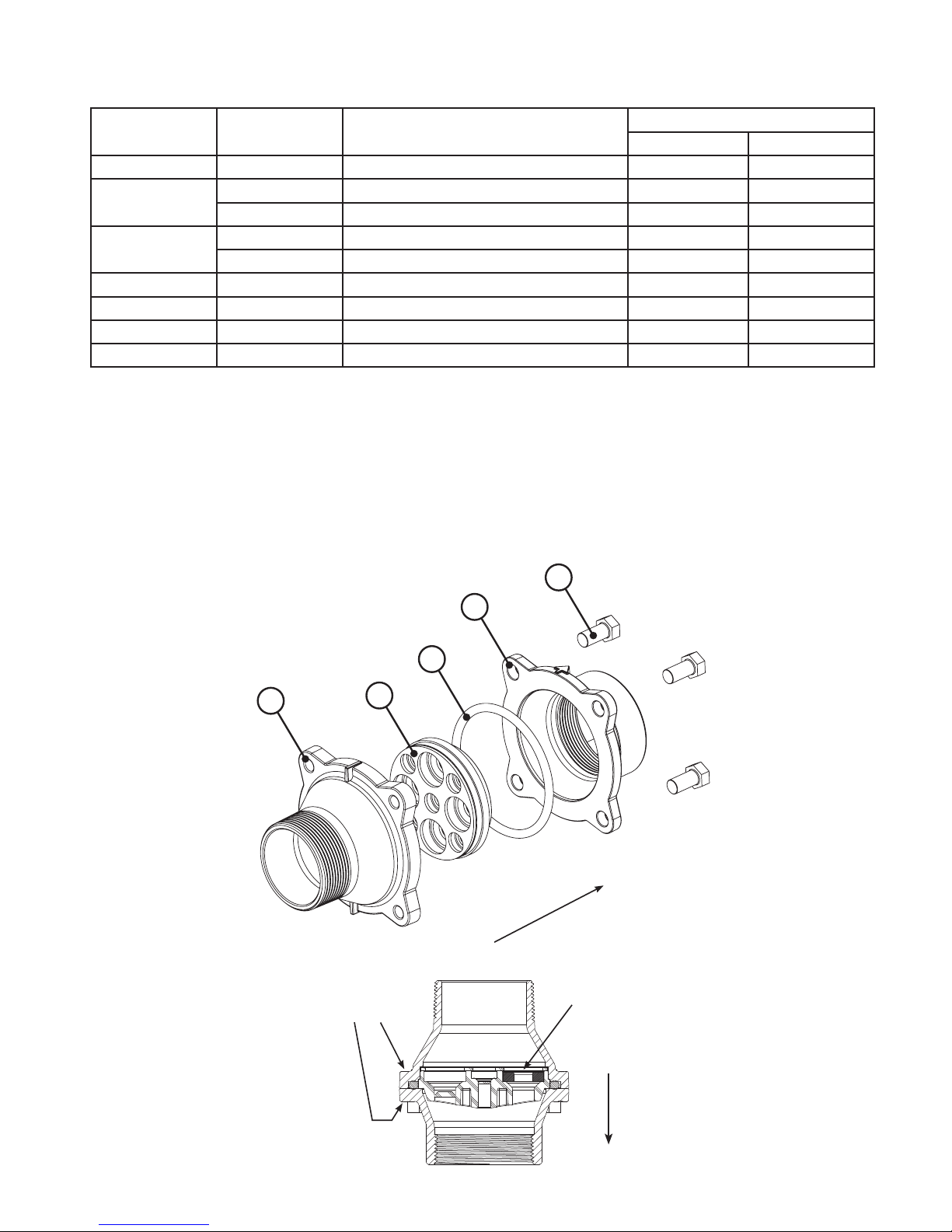
Page 52 WS2H and WS3 Manual
MXF STAINLESS STEEL, 9-225 GPM
Drawing
No.
1
Order No. Description
V3764 V3764BSPT
V3765-01 WS3 DLFC HOUSING NPT 1
V3765BSPT-01 WS3 DLFC HOUSING BSPT 1
Quantity
2 V3766 WS3 DLFC RETAINER 1
3 V3767 WS3 DLFC RETAINER COVER 1 1
4 V3768 WS3 DLFC RETAINER RING 1 1
5 V3769 O-RING 336 1-2 1-2
6 V3190-XX See DLFC table 1-9
Interlock between two V3766’s
Larger hole for DLFC installation
5
Positioning
of V3767 into
V3766
6
1
6
3
1
1
4
3
5
1
1-9
V3768
retainer ring
position if
two V3766
are used
Assemblies are shipped without drain line ow control (DLFC) washers.
Assembly instructions:
1. Determine the desired ow rate. Select a combination of V3190-XXX’s to arrive at the desired ow rate.
2. Using a drill or punch remove the desired knockout(s) in V3766. Each V3766 retainer contains two types of knock
outs. The larger knockouts are removed to install a DLFC. If two V3766 retainers are needed remove the smaller
diameter knockout that lines up with the DLFC installed in the other retainer. One or two V3766 retainers may be
used. When using one V3766 retainer V3190-XXX must be installed in the center hole. When using two V3766
retainers a V3190-XXX must be installed in the center hole of one of the retainers and the center hole on the other
retainer must remain open.
3. Smooth hole(s).
4. Install appropriate size(s) of drain line ow control washers. Pay close attention to proper DLFC orientation.
5. Assemble. Each V3766 retainer must have a V3769 o-ring installed. One each of the V3767 retainer cover and V3768
retainer ring must be used whether one or two V3766 retainers are used. The positioning of the V3768 retainer ring
varies depending on the number of V3766 retainer(s) used. Properly orientate the V3766(s) in the direction of ow.
6. Properly orientate the complete assembly in the direction of ow. Inlet and outlet threads are 3”.

WS2H and WS3 Manual Page 53
DRAIN LINE FLOW CONTROL WASHERS
Order No. Description
V3162-007 .7 GPM Drain line ow control
V3162-010 1.0 GPM Drain line ow control
V3162-013 1.3 GPM Drain line ow control
V3162-017 1.7 GPM Drain line ow control
V3162-022 2.2 GPM Drain line ow control
V3162-027 2.7 GPM Drain line ow control
V3162-032 3.2 GPM Drain line ow control
V3162-042 4.2 GPM Drain line ow control
V3162-053 5.3 GPM Drain line ow control
V3162-065 6.5 GPM Drain line ow control
V3162-075 7.5 GPM Drain line ow control
V3162-090 9.0 GPM Drain line ow control
V3162-100 10.0 GPM Drain line ow control
V3190-090 9.0 GPM Drain line ow control
V3190-100 10.0 GPM Drain line ow control
V3190-110 11.0 GPM Drain line ow control
V3190-130 13.0 GPM Drain line ow control
V3190-150 15.0 GPM Drain line ow control
V3190-170 17.0 GPM Drain line ow control
V3190-200 20.0 GPM Drain line ow control
V3190-250 25.0 GPM Drain line ow control
All DLFC housings ship without DLFC installed.
Select control from table for proper
backwash, based on media manufacturer's
recommendations.
Flow Rate
Identication
Tooling
Identication
Flow Rate
Identication
Tooling
Identication
V3162-XXX
V3162-xx
V3190-XXX
V3190-xx
5/8"
Proper DLFC orientation
directs water ow towards
the washer face with rounded
edge & identication.
1"
Proper DLFC orientation
directs water ow towards
the washer face with rounded
edge & identication.

Page 54 WS2H and WS3 Manual
WS2H/ WS3 TROUBLE SHOOTING GUIDE
Problem Possible Cause Solution
a. No power at electric outlet
b. Control valve Power Adapter not
plugged into outlet or power cord
end not connected to PC board
connection
c. Improper power supply
1. No Display on POD
2. POD does not display correct
time of day
3. Display does not indicate
that water is owing. Refer
to user instructions for how
the display indicates water is
owing
4. Control valve regenerates at
wrong time of day
5. Time of day ashes on and off a. Power outage a. Reset time of day.
6. Control valve does not
regenerate automatically
when the REGEN button is
depressed and held.
d. Poor connection between POD
connector and PC Board.
e. Defective Power Adapter
f. Defective PC Board
a. Power Adapter plugged into electric
outlet controlled by light switch
b. Tripped breaker switch and/or
tripped GFI
c. Power outage
d. Defective PC Board
a. Bypass/ isolation valve in bypass
position
b. Meter is not connected to meter
connection on PC Board
c. Restricted/ stalled meter turbine
d. Meter wire not installed securely
into three pin connector
e. Defective meter
f. Defective PC Board
a. Power outage
b. Time of day not set correctly
c. Time of regeneration set incorrectly
d. Control valve set at “on 0”
(immediate regeneration)
Defective PC Board
a.
b. For the case of systems, another
unit in regen would not allow
another unit to go into regeneration.
a. Repair outlet or use working outlet
b. Plug Power Adapter into outlet or
connect power cord end to PC Board
connection
c. Verify proper voltage is being delivered
to PC Board
d. Check connector on POD, possible
broken wire or terminal pin not inserted
properly in connector. Clean pins on
PC Board by plugging & unplugging the
POD connector a few times to remove
excess protective coating.
e. Replace Power Adapter
f. Replace PC Board
a. Use uninterrupted outlet
b. Reset breaker switch and/ or GFI switch
c. Reset time of day
d. Replace PC Board
a. Turn bypass/ isolation handles to place
in service position
b. Connect meter to three pin connection
labeled FLOW on PC Board
c. Remove meter and check for rotation or
foreign material
d. Verify meter cable wires are installed
securely into three pin connector
labeled FLOW
e. Replace meter
f. Replace PC Board
a. Reset time of day.
b. Reset to correct time of day
c. Reset regeneration time
d. Check programming setting and reset to
dEL (for a delayed regen time)
a. Replace PC Board
b. Wait for unit in regeneration to nish

WS2H and WS3 Manual Page 55
WS2H/ WS3 TROUBLE SHOOTING GUIDE (CONTINUED)
Problem Possible Cause Solution
7. Control valve does not
regenerate automatically
but does when the REGEN
button is depressed and
held.
8. Hard or untreated water is
being delivered
9. Control valve uses too much
regenerant
a. Bypass/ isolation valves in bypass
position
b. Meter is not connected to meter
connection on PC Board
c. Restricted/ stalled meter turbine
d. Incorrect programming
e. Meter wire not installed securely into
three pin connector
f. Defective meter
g. Defective PC Board
Check water quality directly at unit
outlet
1. Water quality is good
a) Bypass/ isolation valves are open
or faulty
2. Water quality is poor
a) Damaged seal/stack assembly
b) Faulty riser tube or seal
c) Control valve body type and piston
type mix matched
3. Media is exhausted, water quality is
poor
a) Higher than anticipated water
usage
b) Meter not registering
c) No regenerant or low level of
regenerant in regenerant tank
d) Control fails to draw in regenerant
e) Water quality uctuation
f) Fouled media bed
a. Improper re ll setting or re ll ll ow
control is not sized properly
b. Improper program settings
c. Control valve regenerates frequently
a. Turn bypass/ isolation valves handles
to place in service position
b. Connect meter to three pin
connection labeled FLOW on PC
Board
c. Remove meter and check for rotation
or foreign material
d. Check for programming error
e. Verify meter cable wires are installed
securely into three pin connector
labeled FLOW
f. Replace meter
g. Replace PC Board
1. External Bypass Leak
a) Fully close bypass/ isolation valves
or replace
2. Internal Bypass Leak
a) Replace seal/stack assembly
b) Verify seal placement &
engagement with riser
c) Verify proper control valve body
type and piston type match
3. No internal leaks
a) Check program settings or
diagnostics for abnormal water
usage
b) See Troubleshooting Guide #3
c) Check refill setting in programming.
Check refill flow control for
restrictions or debris and clean or
replace, check refill flow control rate
for proper fill time.
d) Refer to Troubleshooting Guide # 12
e) Test water and adjust program
values accordingly
f) Replace media bed
a. Check re ll setting and check re ll
ow control for proper re ll rate.
b. Check program setting to make sure
they are speci c to the water quality
and application needs
c. Check for leaking xtures that may
be exhausting capacity or system is
undersized

Page 56 WS2H and WS3 Manual
WS2H/ WS3 TROUBLE SHOOTING GUIDE (CONTINUED)
Problem Possible Cause Solution
a. Check incoming water pressure
– water pressure must remain at
minimum of 25 psi
b. Inspect and clean or replace injector,
or replace injector
for the application
c. Check drain line for restrictions or
debris and clean
d. Check seal/ stack assembly and
piston for damage and replace
e. Program proper draw time needed
f. Program proper re ll time needed
g. Locate vacuum leak and x
1. Excess from ll cycle
a) Verify program settings
b) Visual inspection / measure volume
output into container
2. See Troubleshooting Guide #12
a. Remove injector and clean or replace
b. Replace regenerant piston
c. Inspect regenerant line for air leak
d. Inspect drain line and clean to correct
restriction
e. Shorten length and/or height
f. Check incoming water pressure
– water pressure must remain at
minimum of 25 psi
g. Inspect seal stack assembly for
damage and replace
a. Upon power being restored control
will nish the remaining regeneration
time. Reset time of day.
b. Replace seal/ stack assembly
c. Replace piston assembly
d. Re-tighten the drive cap assembly
Supply Compatibility
with correct size
10. Residual regenerant being
delivered to service
11. Excessive water in
regenerant tank
12. Control valve fails to draw in
regenerant
13. Water running to drain
14. Motor drives intermittently
during regeneration.
a. Low water pressure
b. Plugged, fouled, or incorrect injector
size
c. Restricted drain line
d. Damaged seal/ stack assembly or
piston allowing leakage during draw
e. Draw time too short
f. Excessive re ll
g. Vacuum leak in draw line / elbow
1. Tank is being over lled
a) Improper program settings
b) Missing re ll ow controller
2. Previous regenerant is not being
drawn out
a. Injector is plugged
b. Faulty regenerant piston
c. Regenerant line connection leak
d. Drain line restriction or debris cause
excess back pressure
e. Drain line too long or too high
f. Low water pressure
g. Damaged seal/ stack assembly
a. Power outage during regeneration or
unit is currently in regeneration
b. Damaged seal/ stack assembly
c. Piston assembly failure
d. Drive cap assembly not tightened
properly
a. Low power a. See Table 2 Software and Power

WS2H and WS3 Manual Page 57
WS2H/ WS3 TROUBLE SHOOTING GUIDE (CONTINUED)
Problem Possible Cause Solution
a. Disconnect power, make sure motor
is fully engaged, check for broken
wires, make sure two pin connector
on motor is connected to the two
pin connection on the PC
labeled REGEN. Press NEXT and
REGEN buttons for about 3 seconds
to resynchronize software with piston
position.
b. Properly snap PC Board into drive
bracket and then Press NEXT and
REGEN buttons for about 3 seconds
to resynchronize software with piston
position.
c. Replace missing gears
d. Clean or replace reduction gear
e. Clean or replace PC Board
a. Open up control valve and pull out
piston assembly and seal/ stack
assembly for inspection. Press NEXT
and REGEN buttons for about 3
seconds to resynchronize software
with piston position.
b. Check piston and seal/ stack
assembly, check reduction gears,
check drive bracket and main drive
gear interface. Press NEXT and
REGEN buttons for about 3 seconds
to resynchronize software with piston
position. Check that pinion is not
pressed up tight against motor
c. Loosen main drive gear. Press NEXT
and REGEN buttons for about 3
seconds to resynchronize software
with piston position. Verify free
motion by rotating main drive gear by
hand, driving piston in and out
d. Verify that proper voltage is being
supplied. Press NEXT and REGEN
buttons for about 3 seconds to
resynchronize software with piston
position.
Board
15. Err – 1001 = Control unable
to sense motor movement
16. Err – 1002 = Control valve
motor ran too short and was
unable to nd the next cycle
position and stalled
a. Motor not inserted fully to engage
pinion, motor wires broken or
disconnected
b. PC Boar
drive bracket
c. Missing reduction gears
d. Damaged or dirty reduction gear
re ectors
e. Faulty or dirty optics on back of PC
board
a. Foreign material is lodged in control
valve
b. Mechanical binding
c. Main drive gear too tight
d. Improper voltage being delivered to
PC Board
d not properly snapped into

Page 58 WS2H and WS3 Manual
WS2H/ WS3 TROUBLE SHOOTING GUIDE (CONTINUED)
Problem Possible Cause Solution
17. Err – 1003 = Control valve
motor ran too long and was
unable to nd the next cycle
position
18. Err - 14001 = Message
queue full
19. Err -15003 = Motorized
Bypass or MAV for NHBP
valve motor ran too long
and unable to nd the
proper park position
Motorized Alternating Valve
= MAV
No Hard Water Bypass
= NHBP
a. Motor failure during a regeneration
b. Foreign matter built up on piston and
stack assemblies creating friction and
drag enough to time out motor
c. Drive bracket not snapped in properly
and out of position enough that
reduction gears and drive gear do not
interface
d. Low voltage slowing drive
a. Master PC Board did not receive a
response from slave units.
a. Control valve programmed for
ALT A or noHbP without having
a motorized drive securely
connected to the 2 pin terminal
labeled “BYPASS” on the main
PC Board
b. Poor wire connection
c. Excess drag causing timeout
before stall
d. Motorized Bypass or MAV for
NHBP motor not fully engaged
with reduction gears
a. Check motor connections then Press
NEXT and REGEN buttons for about
3 seconds to resynchronize software
with piston position.
b. Replace piston and stack assemblies.
Press NEXT and REGEN buttons for
about 3 seconds to resynchronize
software with piston position.
c. Snap drive bracket in properly then
press NEXT and REGEN buttons for
about 3 seconds to resynchronize
software with piston position.
d. See Table 2 Software and Power
Supply Compatibility
a. Press NEXT and REGEN buttons for
about 3 seconds to resynchronize
software with piston position.
a. Press NEXT and REGEN
buttons for about 3 seconds
to resynchronize software with
piston position. Then re-program
valve to proper setting
b. Remove power and check
connection for Motorized Bypass
or MAV for NHBP motor to PC
Board two pin connection labeled
BYPASS. Make sure wires in
connector are inserted securely
and no wires are broken. Clean
pins on PC Board by plugging
and unplugging the connector
a few times to remove excess
protective coating. Press NEXT
and REGEN buttons for about
3 seconds to resynchronize
software with piston position.
c. Open up Motorized Bypass or
MAV for NHBP to check for
obstructions
d. Properly insert motor into casing,
do not force into casing. Press
NEXT and REGEN buttons for
about 3 seconds to resynchronize
software with piston position.

WS2H and WS3 Manual Page 59
WS2H/ WS3 TROUBLE SHOOTING GUIDE (CONTINUED)
Problem
20. Err – 15010 = Motorized
Bypass or MAV for NHBP
valve motor ran too short
(stalled) while trying to drive
off-line
Motorized Alternating Valve
= MAV
No Hard Water Bypass
= NHBP
21. Err – 15011 = Motorized
Bypass or MAV for NHBP
valve motor ran too short
(stalled) while trying to drive
on-line
Motorized Alternating Valve
= MAV
No Hard Water Bypass
= NHBP
Possible Cause Solution
a. Foreign material is lodged in
Motorized Bypass or MAV for NHBP
valve
b. Mechanical binding
a. Foreign material is lodged in
Motorized Bypass or MAV for NHBP
valve
b. Mechanical binding
a. Open up Motorized Bypass or MAV
for NHBP and check for foreign
material. Press NEXT and REGEN
buttons for about 3 seconds to
resynchronize software with piston
position.
b. Check poppet drive assembly or
piston and seal/ stack assembly,
check reduction gears, drive gear
interface, and check Motorized
Bypass or MAV for NHBP black drive
pinion on motor. Press NEXT and
REGEN buttons for about 3 seconds
to resynchronize software with piston
position.

Page 60 WS2H and WS3 Manual
WS2H/ WS3 TROUBLE SHOOTING GUIDE (CONTINUED)
Problem Possible Cause Solution
Correct all errors on satellite units before
attempting to reset error on master
22. # of units error:
Communications has
been broken with the
unit speci ed in the error
message. These errors are
logged as 16K series errors
as follows:
16001: error with unit 2
16002: error with unit 3
16003: error with unit 4
23. Err – 17000 = MAV for
Separate Source valve
motor ran too long while
trying to nd proper park
position
a. System is programmed for the
wrong number of units or a Slave
unit is in “error # of units” mode
due to loss of power.
b. Poor connection on PC Boards
c. More than one unit has determined
that it is the master control
a. Control valve programmed for “ON
SEP In” with out having a MAV for
separate source attached
b. MAV for separate source motor
wire not connected to System
Board or poor connection
c. MAV for separate source motor not
fully engaged with reduction gears
a. Pressing any button while in the # of
units error will enter the user into the
setting screen. Adjust to the correct
units for the system and press NEXT to
exit the set up screen. Press NEXT and
REGEN buttons for about 3 seconds
to resynchronize software with piston
position. Re-program valve to proper
setting.
b. Make sure wires in connector are
inserted securely and no wires are
broken. Clean pins on PC Board by
plugging and unplugging the connector
a few times to remove excess
protective coating. Press NEXT and
REGEN buttons for about 3 seconds
to resynchronize software with piston
position.
c. Press NEXT and REGEN buttons for
about 3 seconds to resynchronize
software with piston position. Then
re-program each valve to operate as
single individual unit. Re-program the
control that is to be the master control
and it will lter down the programming
to the slave controls automatically.
a. Press NEXT and REGEN buttons for
about 3 seconds to resynchronize
software with piston position. Reprogram valve to proper setting
b. Remove power and check connection
on MAV for separate source motor wire
to System Board two pin connection
labeled AUX DRIVE. Make sure wires
in connector are inserted securely
and no wires are broken. Clean pins
on System Board by plugging and
unplugging the connector a few times
to remove excess protective coating.
Press NEXT and REGEN buttons for
about 3 seconds to resynchronize
software with piston position.
c. Properly insert motor into casing, do
not force into casing. Press NEXT and
REGEN buttons for about 3 seconds
to resynchronize software with piston
position.

WS2H and WS3 Manual Page 61
WS2H/ WS3 TROUBLE SHOOTING GUIDE (CONTINUED)
Problem Possible Cause Solution
24. Err – 17002 = MAV for
Separate Source valve
motor ran too short while
trying to nd proper park
position
25. Err – 18000 = Reset was
performed, this error
code will display in the
diagnostics under the error
log
26. Err – 18001 = Power loss,
this error code will display in
the diagnostics under error
log
27. Err – 18002 = Power
restored, this error code will
display in the diagnostics
under error log
a. Foreign material is lodged in MAV
for separate source valve
b. Mechanical binding
a. Press the NEXT and REGEN
buttons for about 3 seconds to
resynchronize software with piston
position.
a. When power is lost a signal is sent
to log the power loss
a. When power is restored a signal
is sent to log the power being
restored
a. Open up MAV for separate source
and check for foreign material. Press
NEXT and REGEN buttons for about 3
seconds to resynchronize software with
piston position.
b. Check poppet drive assembly or piston
and seal/ stack assembly, check
reduction gears, drive gear interface,
and check MAV for separate source
black drive pinion on motor. Press
NEXT and REGEN buttons for about 3
seconds to resynchronize software with
piston position.

Page 62 WS2H and WS3 Manual

WS2H and WS3 Manual Page 63

Page 64 WS2H and WS3 Manual
Revision History:
2/3/2017
PAGE 4:
New table
PAGE 8:
New drawing
PAGE 9:
New drawing
PAGE 37:
Removed Distributer Pipe Height
3/10/2017
PAGE 5:
V3461-01 WS2H/3 AC ADAPTER 20V
216.04 or greater 1.13 or greater 20 VAC
V3461EU-01 WS2H/3 AC ADAPTER EU 20V
V3461UK-01 WS2H/3 AC ADAPTER UK 20V
12/5/2017
PAGE 44 & 45:
1 V3275 WS2H/3 SCW BSHD SS3/8-16X2-1/4 (7/32” hex allen wrench required) 4
1/10/2018
PAGE 46:
Remove the word “PVC”
2/12/2018
PAGE 4:
Output Voltage 18V, 20V or 24V AC (see Table 2) 18V, 20V or 24V AC
PAGE 5:
V3461-01 WS2H/3 AC ADAPTER 18V
V3461EU-01 WS2H/3 AC ADAPTER EU 18V
V3461UK-01 WS2H/3 AC ADAPTER UK 18V
See Table 2 Software and Power
Supply Compatibility for option
PAGE 43:
Not Shown
216.04 or greater 1.13 or greater
V3461-01 WS2H/3 AC ADAPTER 18VAC 1
V3461EU-01 WS2H/3 AC ADAPTER EU 18VAC
V3461UK-01 WS2H/3 AC ADAPTER UK 18VAC
20 VAC
18 VAC
selection
Form No. V3215 – 2/12/2018 U.S. Patents: 6,402,944 • 6,444,127 • 6,776,901
 Loading...