

Page 1

WS1”, 1.5”& 2” Series NRU
Installation Operation Maintenance Manual
Installation
Operation
Maintenance
Manual
Simplex Nitrate Removal Unit
WithWS1”, 1.5” & 2” Series Valve
Models 20 ltr - 750 ltr
Simplex Clack NRU rev 1 Page 1 of 27
Page 2

WS1”, 1.5”& 2” Series NRU
Installation Operation Maintenance Manual
1.0 PARTS LIST
1.1 BASIC PARTS LIST.....................................................................................................................3
1.2 MISSING OR DAMAGED GOODS..............................................................................................3
2.0 TEMPORARY STORAGE
3.0 REGENERATION
3.1 The Regeneration Process....................................................................................................3
3.2 METER CONTROL OF REGENERATION.....................................................................................4
3.3 TIME CLOCK CONTROL OF REGENERATION INITIATION..........................................................4
4.0 PRE-INSTALLATION CHECKS
4.1 MECHANICAL...........................................................................................................................4
4.1.1 Foundation/Drainage .......................................................................................................4
4.1.2 Operating Space ...............................................................................................................5
4.1.3 Incoming Water................................................................................................................5
4.1.4 Pipework...........................................................................................................................5
4.1.5 Water Supply Company Requirements............................................................................5
4.2 ELECTRICAL..............................................................................................................................6
5.0 ASSEMBLY/INSTALLATION
5.1 MECHANICAL...........................................................................................................................6
5.1.1 Pipework...........................................................................................................................6
5.1.2 Assembly...........................................................................................................................6
6.0 PROGRAMMING
6.1 INTRODUCTION .......................................................................................................................7
6.2 CONTROLLER SETTING.............................................................................................................7
6.2.1 Setting the Time of Day....................................................................................................8
6.3 Factory Programming
7.0 COMMISIONING ....................................................................................................................12
8.0 ROUTINE MONITORING.............................................................................................................13
9.0 FAULT FINDING AND RECTIFICATION........................................................................................14
9.1 NO FLOW TO SERVICE ...........................................................................................................14
9.2 POOR TREATED WATER QUALITY..........................................................................................14
9.3 NO REGENERATION...............................................................................................................15
9.4 UNSATISFACTORY CAPACITY BETWEEN REGENERATIONS....................................................15
10.0 WARRANTY AND SERVICE ...................................................................................................15
10.1 AFTER SALE WARRANTY ......................................................................................................15
11.0 Technical Data
11.1 Process and Operating Data
11.1.1 WS1 20-80 L...........................................................................................................16
11.1.2 WS1 100-350 L.......................................................................................................17
11.1.3 WS1.5 100-500 L....................................................................................................18
11.1.4 WS2 150-750 L.......................................................................................................19
11.2 ENGINEERING DATA
11.2.1 WS1 20-80 L...........................................................................................................20
11.2.2 WS1 100-350 L.......................................................................................................21
11.2.3 WS1.5 100-500 L....................................................................................................22
11.2.4 WS2 150-750 L.......................................................................................................23
12.0 FACTORY PROGRAM................................................................................................................24
13.0 CE Certificate
..................................................................................................................................3
..............................................................................................................3
..........................................................................................................................3
......................................................................................................4
........................................................................................................6
.........................................................................................................................7
............................................................................................................9
........................................................................................................................16
........................................................................................16
.....................................................................................................20
..........................................................................................................................27
Simplex Clack NRU rev 1 Page 2 of 27
Page 3

WS1”, 1.5”& 2” Series NRU
Installation Operation Maintenance Manual
1.0 PARTS LIST
1.1 BASIC PARTS LIST
1. Clack VALVE C/W TRANSFORMER
2. VESSEL & RISER
3. BRINE TANK
4. INSTRUCTIONS
5. REDUCER (if required)
6. RESIN
1.2 MISSING OR DAMAGED GOODS
Immediately on receipt of the goods, it is advisable to check that all items
ordered have been received. If you have any doubt that goods have been
supplied as requested, please contact your supplier immediately. If any
items are missing or damaged, the carrier and your supplier must be notified
within 2 days of receipt if a claim is to be made.
2.0 TEMPORARY STORAGE
If installation is not to start immediately after delivery, the equipment should
be stored in a clean dry area, where it will not be damaged, or be subjected
to temperatures below freezing.
3.0 REGENERATION
3.1 The Regeneration Process
The regeneration process consists of six stages:-
1. Backwash
drain. As it does so, it loosens the ion exchange beads, removes any resin
'fines' (i.e. small pieces of broken beads etc.) and cleans off any particles of
dirt or pipework corrosion products which may have accumulated during the
service cycle.
- Water flows upwards through the resin bed, and out to a
2/3. Brine/Slow Rinse
concentrated salt -solution is drawn from the brine tank, blended with water to
reduce the concentration to the correct level, and passed down through the
resin. When the required quantity of brine has been drawn in, the water flows
alone to push the remaining brine through the resin at the correct rate, and
ensure that all of the resin sees the right amount of regenerant.
Simplex Clack NRU rev 1 Page 3 of 27
- During the first part of this stage, the
Page 4

WS1”, 1.5”& 2” Series NRU
Installation Operation Maintenance Manual
4. Backwash (2nd)
backwash allowing for optimum regeneration, efficiency and cleaning of the
resin bed. Water flows as in the first backwash cycle.
5. Fast Rinse
away the residual brine and Calcium and Magnesium salts from the resin and
re-packing the resin bed. This is carried out down flow with water flowing
through the resin in the direction of service.
6. Salt Tank Refill
sufficient to dissolve the correct amount of salt for the next
regeneration is returned to the salt tank. When this has finished, the unit
automatically returns to service.
- This follows the brine and slow rinse cycle, and entails rinsing
- This valve has the unique facility of performing a second
- Following the fast rinse, a quantity of water
3.2 METER CONTROL OF REGENERATION
On meter controlled valves a water meter is installed in the outlet from the
nru, to measure the volume of water which passes to service. The internal
turbine rotates with the flow of water and reports its rate of rotation through
Hall-effect circuitry to the printed circuit board. When the reading reaches
zero the valve will automatically regenerate that night at 2 am for delayed
regeneration nrus or immediately for immediate regeneration nrus.
3.3 TIME CLOCK CONTROL OF REGENERATION INITIATION
Time clock configuration valves initiate regeneration at a pre-set time after
a pre-set number of days. The frequency of regenerations are adjustable
on programming the timer (Regeneration control).
4.0 PRE-INSTALLATION CHECKS
4.1 MECHANICAL
4.1.1 Foundation/Drainage
The nru will not require any special foundations, provided that a firm, level
area which is capable of supporting the working weight is available. (See
Engineering Data, Section 11.2)
Unwanted water from the regeneration process must flow to drain, and so
an open drain or gully, capable of passing the necessary flow is required
(see Process and Operating Data, 11.1, for relevant flows). The total flow
of water to drain depends on site conditions, but will be approximately 6
times the resin volume. Preferably the drain should be level with or no higher
than 500mm above the nru valve.
A second drain is required for the brine tank overflow. This is a safety drain
which will only discharge water if there is a malfunction in the control
valve. Where possible this should be installed through an outside wall
like a cistern overflow, where it will give a visual indication of any failure.
Simplex Clack NRU rev 1 Page 4 of 27
Page 5

WS1”, 1.5”& 2” Series NRU
Installation Operation Maintenance Manual
4.1.2 Operating Space
The space occupied by the nru can be found in the Engineering Data
(Section 11.2).
Access will be required to refill the salt tank, and to carry out
adjustments or maintenance on the equipment. It is therefore
recommended that a minimum of 500mm clearance be allowed in front of
the unit for this purpose.
4.1.3 Incoming Water
The raw water to be fed to the nru must comply with the following:-
1. Available at all times at a flow equal to or greater than
the required service flow
2. At a pressure between 1.7 and 8.0 bar
3. Temperature between 4 and 38oC
4. Suspended solids less than 1 ppm
5. Iron less than 0.2 ppm, Manganese less than 0.1 ppm,
Free Chlorine less than 1 ppm if temperature is less than
15oC, less than 0.3 ppm if temperature higher (up to 30oC)
4.1.4 Pipework
Pipework to be connected to the nru should not have an excessive
amount of nitrate and sulphate scale deposit. Piping that is heavily built up
with scale (or Iron deposits) should be replaced.
Make sure that the pipework can be connected to the nru in such a way as
to impose no stresses on the control valve, and that it is properly aligned
and supported.
A system for the complete by-passing and isolation of the nru should be
installed.
4.1.5 Water Supply Company Requirements
It is essential that if the equipment is to be connected directly to a mains
water supply, the local bylaws must be adhered to. These cover both
plumbing and the prevention of backflow into the mains. If there is any
doubt, the local water inspector should be consulted, but in general, the
installation of a 'Double check valve assembly' conforming to BS6282 part 2
will be required in the feed pipework to the nru.
If the pressure available from the mains is not adequate it will be
necessary to install a booster pump arrangement. Such a system would
be covered by additional bylaws, and the water storage tank needed must
comply with these.
Simplex Clack NRU rev 1 Page 5 of 27
Page 6

WS1”, 1.5”& 2” Series NRU
Installation Operation Maintenance Manual
4.2 ELECTRICAL
A continuous supply of 240v, 5 VA is required. The nru itself is 12 volt but a
plug in 240v/12v transformer is supplied and should be connected to an
uninterrupted mains supply, which is separately 1 Amp fused, and does
not have any additional switch.
5.0 ASSEMBLY/INSTALLATION
5.1 MECHANICAL
Check all the items against the parts list and shipping documents, and
ensure you have them all before starting work. In addition to the nru
you will require installation materials and basic tools, (i.e., spanners,
screwdrivers etc., and PTFE tape)
5.1.1 Pipework
Pipework should be assembled incorporating the features shown in the
Installation Diagram, Section 14.1. It is essential that inlet and outlet
isolating valves and a by-pass valve are provided, and that the water main
is protected by a double check valve where appropriate (see Local Water
Bye-laws).
Pipework can be constructed from any normally acceptable material
(Copper, Galvanised, Plastic), provided it is properly supported and
aligned. Ensure that the pipe is sufficiently large to accommodate the flow
of water required, making due allowance for the pressure drop between
the nru and the point of discharge of soft water.
NOTE: IF BRAZED OR SOLDERED FITTINGS ARE TO BE USED, THE
PIPE WORK MUST BE DISCONNECTED FROM THE VALVE DURING
HEATING AND COOLING. EXCESS HEAT CAN CAUSE PERMANENT
DAMAGE TOSOME OFTHE VALVE COMPONENTS.
5.1.2 Assembly
If possible place the pressure vessel on its final location before filling. Check
that the distributor tube, with its yellow top cover, is in place and using a
funnel slowly pour in the resin taking care not to spill any on the floor. Ensure
that the distributor tube remains central in the vessel during filling. After
emptying all the bags, the vessel should be almost 75-80% full. This is to
allow for the rising of the resin bed during backwash. Once the vessel is
filled, immediately sweep up any spilled resin.
Remove cover from distributor tube and brush any beads of resin out of
the threads in the neck of the vessel.
Simplex Clack NRU rev 1 Page 6 of 27
Page 7

WS1”, 1.5”& 2” Series NRU
Installation Operation Maintenance Manual
Unpack valve and skip down over the distributor tube. Screw the valve in to
the resin vessel, taking care not to cross the threads. Excessive force
should not be needed as the valve is running in to the vessel. Finally
tighten to approximately 20 ft/lbs torque. Adjust position of vessel to line
up piepwork connections, not the position of the valve on the vessel.
Position the brine tank and connect brine line to the bulkhead
connector above the overflow (3/8”). Ensure that a brass insert is
inside the brine line before connecting.
placed
Connect inlet and outlet pipework
male
high pressure pipe and socket unions. Some felxible pipework is
advisable to prevent stress on the vessel as it cycles during service, since
it will expand and contract longitudinally.
Connect drain line to the drain outlet (3/4” male threaded elbow on top
valve). Ensure that there is an air break in the drain line at the sameheight as
the valves to prevent negative pressure on the vessel.
Connect brine line to the brine connection on the valve. Again ensure that a
brass insert is placed inside the brine line before connecting.
Connect power supply to valve and commission.
threaded elbows at rear of valve) using flexibles where possible or rigid
to the valve (1” BSP 90 deg or straight
of
6.0 PROGRAMMING
6.1 INTRODUCTION
It is recommended that the commissioning of the plant is undertaken by a
trained service engineer, who will be able to put the plant into service
quickly, and most efficiently. However, if the services of an experienced
engineer are not available, following the steps outlined below will result in
the system being properly commissioned.
6.2 CONTROLLER SETTING - Site programming mode
All controller settings will require the valve to have the mains supply
switched on. The valve must not be regenerating when controller
settings are adjusted.
Simplex Clack NRU rev 1 Page 7 of 27
Page 8
WS1”, 1.5”& 2” Series NRU
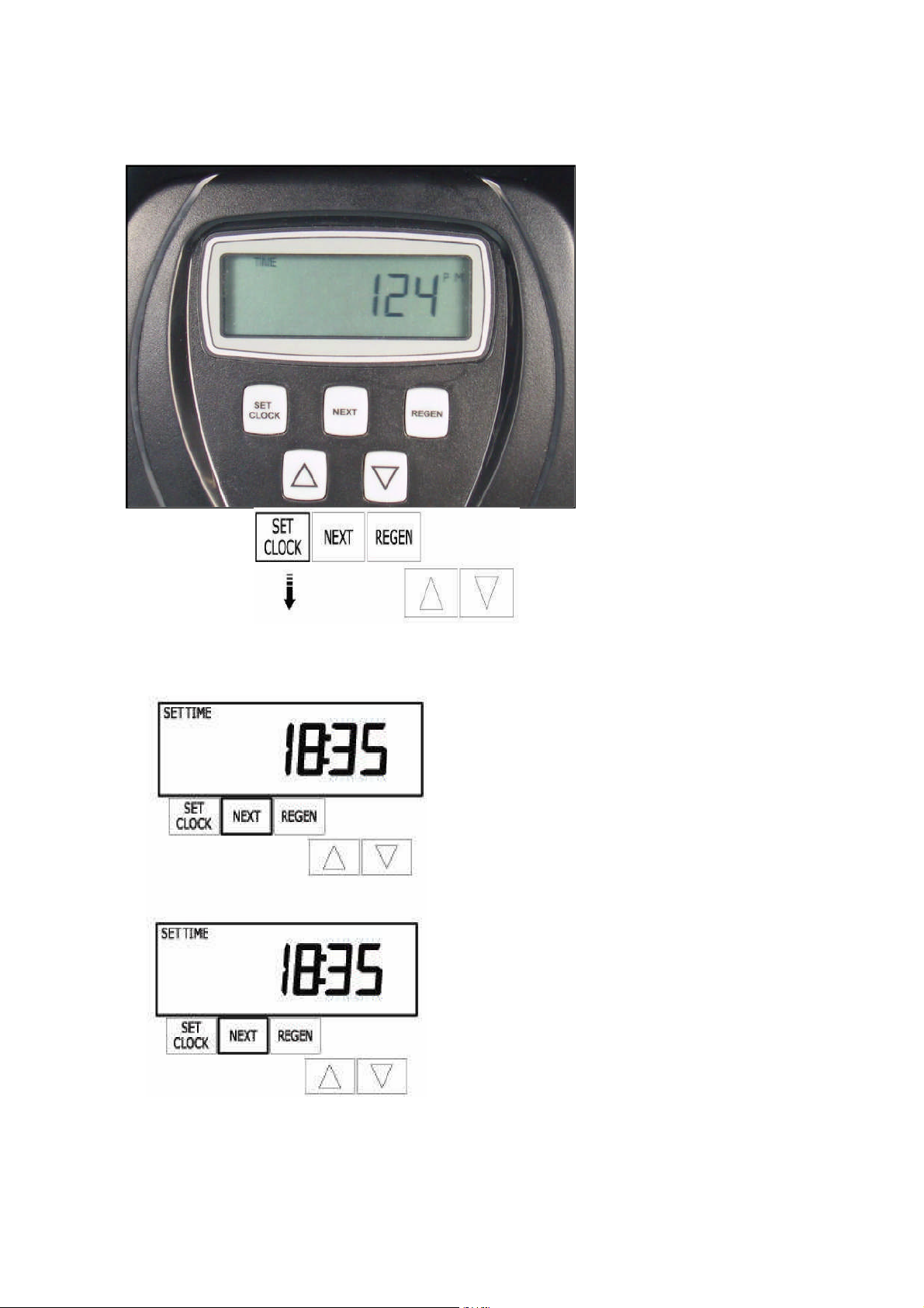
6.2.1 Setting the Time of Day
Installation Operation Maintenance Manual
1. Press SET CLOCK
The nru regeneration cycles have been factory programed. On metered
nrus the volume capacity of the resin in litres has also been entered on a
2. Adjusthours with UP and
DOWN arrows
3. Press NEXT
4.AdjustminuteswithUP
andDOWN arrows.
5.PressNEXTtoreturnto
normal operation
default nitrate and sulphate of 300ppm and a reserve capacity of 33%.
This may need to be altered based on local water nitrate and sulphate
and reserve required for the site (see section 13.1) The time of day for
Simplex Clack NRU rev 1 Page 8 of 27
Page 9
WS1”, 1.5”& 2” Series NRU
Installation Operation Maintenance Manual
regeneration has been entered as 2 AM, this can be changed if
necessary.
6.3 Factory Programming
Regeneration Programming
(Allprogramming below is Factory set)
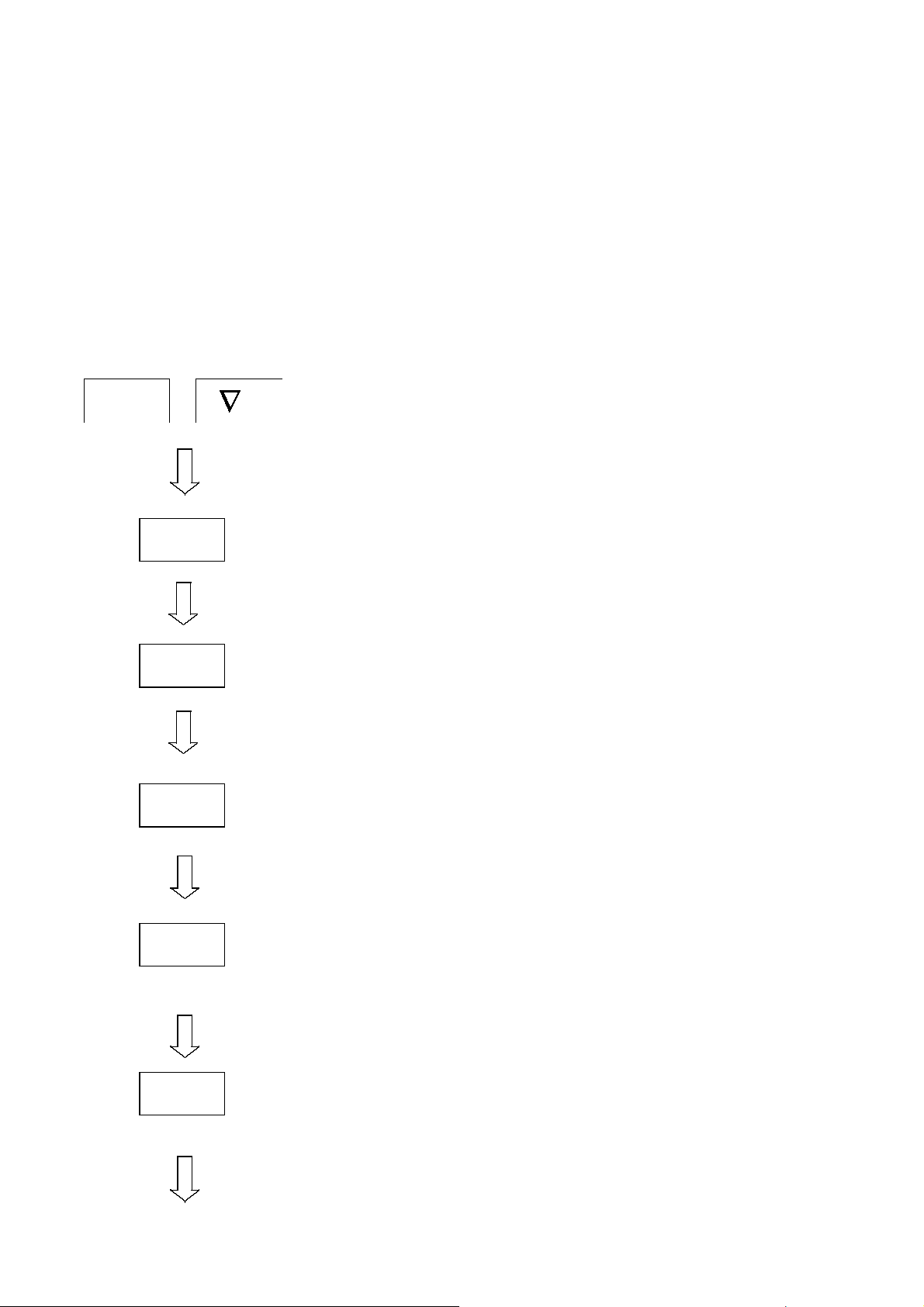
To alter settings – Press “↑” and “↓” keys To back up at any stage – Press
“REGEN” To save any changes – Press “SET CLOCK”
NEXT
Press and hold together for 5 seconds
“Softening” willbe flashing in topleft corner
NEXT
NEXT
NEXT
NEXT
Set 1stcycletime in minutes – BACKWASH
Set2ndcycletimein minutes – BRINE& SLOW
RINSE
Set3rdcycletimein minutes – BACKWASH 2
Set4thcycletimein minutes – FAST RINSE
NEXT
Set 5thcycle time in kilos of salt required per regeneration
– BRINE REFILL except WS2 which is in minutes
Simplex Clack NRU rev 1 Page 9 of 27
Page 10

NEXT
NEXT
NEXT
NEXT
WS1”, 1.5”& 2” Series NRU
Installation Operation Maintenance Manual
Capacity in Kilograms-Set according to Nru Size in
Technical data if metered, ignore if timeclock
Set Auto if metered, off if timeclock
Set type of regeneration required:“NORMAL” –
“on 0” –
Either Delayed or ImmediateRegeneration, whichever
occurs first
Immediate Regeneration
Delayed Regeneration
“NORMAL + on 0” –
NEXT
User Programming
To alter settings
“REGEN”
Press together and hold for 5 seconds
NEXT
– Press
To save any changes
Set Salt to Off
Programming Finished–Return to time of day
“↑” and “↓”
Set Influent Nitrate and sulphate in ppm if
metered, nA if timeclock
keys
To back up at anystage
– Press “SET CLOCK”
– Press
Simplex Clack NRU rev 1 Page 10 of 27
Page 11

NEXT
NEXT
NEXT
WS1”, 1.5”& 2” Series Waternru
Installation Operation Maintenance Manual
Set effluent nitrate and sulphate in ppm if mixing
valve fitted, if no mixing valve fitted then set to 0 if
metered. NA if timeclock.
Set day regeneration override for metered nru’s OR
set frequency of regenerations for Timeclock valves
(1-28 days)
Set time for regeneration hours. TimeforImmediate
regeneration valves cannot be altered and will show “on
0”
NEXT
Returns to time of day
SIMPWS1 REV2 06/08/10 PAGE 11 OF27
Page 12

WS1”, 1.5”& 2” Series Waternru
7.0 COMMISIONING
The objective of commisioning is to fill the nru and brine tank with water,
check for leaks and prepare it for service. The simplest way to
commission the unit is to initiate a regeneration. This will eliminate the
air from the system and flush the resin prior to use.
Manually add water to the brine tank until it is filled approximately 6”
(100mm) from the bottom of the tank.
Before opening the inlet water supply, ensure that the outlet is shut and
switch on the power supply and press the “REGEN” button on the
valve. “Regen today” will appear at the bottom left of the timer, by
continuing to press the “REGEN” button the motor will power up and
move the valve into the backwash position. Slowly open the inlet valve.
At first, air will be expelled from the drain line, followed by water once
the vessel is full. The first quantity of water will have a tan colouration
which is perfectly normal. Allow water to run to drain until the water is
clear.
Installation Operation Maintenance Manual
Next, press the “Regen” button and the motor will move the valve into
the brine and slow rinse position. Ensure that the water level in the
brine tank drops as water is drawn in. During brine and slow rinse
water will slowly run to drain.
Press the “Regen” button 3 more times (after pressing the button once,
wait for the motor to stop before pressing it again) until the valve
reaches the refill stage. Ensure that water is now refilling the brine
tank. Leave to fill for full duration of the cycle and add salt to the brine
tank. The level the water will reach depends on the type of salt used
and the resin volume of the nru
At the end of the refill cycle the motor will automatically move the valve
back into the service position. The nru is now commissioned. Open
the outlet from the nru to run water to service.
Add salt to the brine tank. If tablet salt is used (recommended) then
the cabinet can be filled to the top. If granular salt is used then the
cabinet must only be 3/4 full.
SIMPWS1 REV2 06/08/10 PAGE 12 OF27
Page 13

WS1”, 1.5”& 2” Series nru
Installation Operation Maintenance Manual
8.0 ROUTINE MONITORING
The following recommendations are made to help the user of the
nru confirm that it is performing as required, and to give early
warning of possible problems. The operation of the nru is
completely automatic, and should not require adjustment.
Weekly
Check the treated water nitrate and sulphate with a nitrate
and sulphate test kit. Inspect the level of salt in the salt tank
and refill if necessary.
Monthly
Check raw water nitrate and sulphate, and record. Compare with
original nitrate and sulphate and adjust volume capacity setting if
required (see Section 12.0).
Annually
Inspect and clean/replace as necessary the brine injector, brine screen
and the internal seal spacer set. This should be performed by a
competent engineer familiar with the WS1 valve.
SIMPWS1 REV2 06/08/10 PAGE 13 OF27
Page 14

WS1”, 1.5”& 2” Series nru
Installation Operation Maintenance Manual
9.0 FAULT FINDING AND RECTIFICATION
ModernNitrate Removal Unit areextremelyreliable andunlikely to give
any problems if they are installed and operated correctly.
9.1 NO FLOW TO SERVICE
Check mains pressure is above 1.7 bar.
Check inlet andoutlet isolatingvalves areopen.
Check service outlet valve is open.
Check pressure drop across resin. If excessive, resin may be fouled,
or internals blocked. Initiate a regeneration. If this does not free up
the resin the nru will need to be inspected and serviced by a
competent engineer.
9.2 POOR TREATED WATER QUALITY
Check manual by-pass closed.
Check salt level in salt tank. Refill if necessary.
Trickle flow through conventional ball valve in storage tank. Replace
with Torbeck or Fluidmaster servo valve.
Check raw water pressure above minimum. If flow is less than
minimum, channelling of water can occur in resin. which results in
inadequate treatment.
Check injector strainer and injector not blocked (see Appendix for
drawings). Clean if necessary.
Check brine pick-up screennot blocked. Clean if necessary.
Check brine line not split. Replace if necessary.
Check raw water nitrate and sulphate, and then check if capacity setting
is correct for this nitrate and sulphate (see Section 12.0)
SIMPWS1 REV2 06/08/10 PAGE 14 OF27
Page 15

WS1”, 1.5”& 2” Series nru
Installation Operation Maintenance Manual
9.3 NO REGENERATION
Check electrical supply, fuses etc. satisfactory.
Check control head motor runs by initiating a manual regeneration
(Press “REGEN” button for 5s and then again for a further 5s), listening
for drive motor ‘whirring' as it advances between cycles. Replace if
necessary.
Check internal meter running freely (if fitted) indicated by small black
dot in center of display flashing.
9.4 UNSATISFACTORY CAPACITY BETWEEN
REGENERATIONS
Check condition of resin. It may have become fouled, inhibiting the
regeneration process. If fouled, it should be cleaned or replaced.
Check incoming water for presence of Chlorine. If high, the resin may
have been degraded.
Check raw water pressure. Too high pressure may mean the brine
draw stage of regeneration is not effective
10.0 WARRANTY AND SERVICE
10.1 AFTER SALE WARRANTY
Your nru is covered by a parts warranty for a period of one year from
installation or 14 months from purchase.
Should you have any problems with your nru or require a routine service,
please contact your supplier.
SIMPWS1 REV2 06/08/10 PAGE 15 OF27
Page 16

WS1”, 1.5”& 2” Series nru
Installation Operation Maintenance Manual
11.0 Technical Data
11.1 Process and Operating Data
11.1.1 WS1 20-80 L
PARAMETER UNITS 25L 30L 40L 50L 60L 80L
MAX.SERVICE
FLOW
SYSTEM
CAPACITY
CAPACITY @
200PPM
SALT USED
PER REGEN
SALT
STORAGE
CAPACITY
MAX
OPERATING
TEMP
MAX FLOW
TO DRAIN
INJECTOR WHITE1EWHITE1EBLUE1FYELLOW1GLIGHT
M3/hr 1 1.2 1.6 2 2.4 3.2
Kg
CaCO3
M3 6.25 7.5 10 12.5 15 20
Kg 6.25 7.5 10 12.5 15 20
Kg 80 80 80 120 120 160
O
C 50 50 50 50 50 50
LIT/MIN 5.7 9 9 9 15.14 15.14
1.25 1.5 2 2.5 3 4
BLUE
1J
LIGHT
GREEN
1K
IMPORTANT NOTES
Much of the data quoted in the above table is affected by the inlet pressure,
and so should be regarded as nominal only.
Total flow to drain will be similarly affected and is therefore not quoted, but
will be about 6 times the resin volume.
SIMPWS1 REV2 06/08/10 PAGE 16 OF27
Page 17

WS1”, 1.5”& 2” Series nru
Installation Operation Maintenance Manual
11.1.2 WS1 100-350 L
PARAMETER UNITS 100L 120L 150L 250L 350L
MAX.SERVICE
FLOW
SYSTEM
CAPACITY
CAPACITY @
200PPM
SALT USED
PER REGEN
SALT
STORAGE
CAPACITY
MAX
OPERATING
TEMP
MAX FLOW
TO DRAIN
INJECTOR LIGHT
M3/hr 4 4.3 6 6 6
Kg
CaCO3
M3 25 24 37.5 62.5 87.5
Kg 25 24 37.5 62.5 87.5
Kg 300 300 400 500 750
O
C 50 50 50 50 50
LIT/MIN 19 19 26 37 57
5 6 7.5 12.5 17.5
GREEN
1K
LIGHT
GREEN
1K
LIGHT
GREEN
1K
LIGHT
GREEN
1K
LIGHT
GREEN
1K
IMPORTANT NOTES
Much of the data quoted in the above table is affected by the inlet pressure,
and so should be regarded as nominal only.
Total flow to drain will be similarly affected and is therefore not quoted, but
will be about 6 times the resin volume.
SIMPWS1 REV2 06/08/10 PAGE 17 OF27
Page 18

WS1”, 1.5”& 2” Series nru
Installation Operation Maintenance Manual
11.1.3 WS1.5 100-350 L
PARAMETER UNITS 100L 120L 150L 250L 350L
MAX.SERVICE
FLOW
SYSTEM
CAPACITY
CAPACITY @
200PPM
SALT USED
PER REGEN
SALT
STORAGE
CAPACITY
MAX
OPERATING
TEMP
MAX FLOW
TO DRAIN
INJECTOR
M3/hr 4 4.8 6 10 11.6
Kg
5 6 7.5 12.5 17.5
CaCO3
M3 25 24 37.5 62.5 87.5
Kg 25 24 37.5 62.5 87.5
Kg 300 300 400 500 750
O
C 50 50 50 50 50
LIT/MIN 19 19 26 37 56
YELLOW
15F
YELLOW
15F
GREEN
15G
ORANGE
15H
ORANGE
15H
IMPORTANT NOTES
Much of the data quoted in the above table is affected by the inlet pressure,
and so should be regarded as nominal only.
Total flow to drain will be similarly affected and is therefore not quoted, but
will be about 6 times the resin volume.
SIMPWS1 REV2 06/08/10 PAGE 18 OF27
Page 19

WS1”, 1.5”& 2” Series nru
Installation Operation Maintenance Manual
11.1.4 WS2 150-750 L
PARAMETER UNITS 150L 200L 250L 300L 350L 500L 750L
MAX.SERVICE
FLOW
SYSTEM
CAPACITY
CAPACITY @
200PPM
SALT USED
PER REGEN
SALT STORAGE
CAPACITY
MAX
OPERATING
TEMP
MAX FLOW TO
DRAIN
INJECTOR 2B 2C 2C 2D 2D 2F 2G
BRINE REFILL
BUTTON
M3/hr 6 8 10 12 14 20 24
Kg
CaCO3
M3 37.5 50 62.5 75 87.5 125 187.5
Kg 37.5 50 62.5 75 87.5 125 187.5
Kg 400 400 500 500 750 1000 1500
O
C 50 50 50 50 50 50 50
LIT/MIN 26.5 37.85 37.85 56.78 56.78 94.63 132.4
7.5 10 12.5 15 17.5 25 37.5
8
2.2 2.7 3.2 4.2 5.3 6.5 10
IMPORTANT NOTES
Much of the data quoted in the above table is affected by the inlet pressure,
and so should be regarded as nominal only.
Total flow to drain will be similarly affected and is therefore not quoted, but
will be about 6 times the resin volume.
SIMPWS1 REV2 06/08/10 PAGE 19 OF27
Page 20

WS1”, 1.5”& 2” Series nru
Installation Operation Maintenance Manual
11.2 ENGINEERING DATA
11.2.1 WS1 20-80 L
PARAMETER UNITS 25L 30L 40L 50L 60L 80L
VESSEL SIZE INCH 9x35 10x35 10x44 10x54 12x48 13x54
BRINE TANK
HEIGHT
BRINE TANK WIDTH MM 285 285 285 370 x
TOTAL HEIGHT MM 1100 1100 1390 1590 1420 1590
REAR CLEARENCE
REQUIRED
INLET CONNS INCH 1 1 1 1 1 1
OUTLET CONNS INCH 1 1 1 1 1 1
DRAIN CONNS INCH ¾ ¾ ¾ ¾ ¾ ¾
BRINE TANK
OVERFLOW
DELIVERED
WEIGHT
ELECTRICAL
POWER 240 V 50 HZ
MM 960 960 960 960 960 1040
370 x
430
MM 50 50 50 50 50 50
INCH ½ ½ ½ ½ ½ ½
KG 19 20 21 23 25 30
V/A 1.2 1.2 1.2 1.2 1.2 1.2
430
480
IMPORTANT NOTES
MAXIMUM OPERATING PRESSURE 5.5 BARG MINIMIUM OPERATING PRESSURE 1.7 BARG
HEADROOM ALLOW 100MM GREATER THAN THE OVERALL HEIGHT.
SIMPWS1 REV2 06/08/10 PAGE 20 OF27
Page 21

WS1”, 1.5”& 2” Series nru
Installation Operation Maintenance Manual
11.2.2 WS1 100-350 L
PARAMETER UNITS 100L 120L 150L 250L 350L
VESSEL SIZE INCH 14x65 14x65 16x65 21x62 24x72
BRINE TANK
HEIGHT
BRINE TANK WIDTH MM 700 700 840 880 960
TOTAL HEIGHT MM 1984 1984 1988 2038 2225
REAR CLEARENCE
REQUIRED
INLET CONNS INCH 1 1 1 1 1
OUTLET CONNS INCH 1 1 1 1 1
DRAIN CONNS INCH ¾ ¾ ¾ ¾ ¾
BREIN TANK
OVERFLOW
DELIVERED
WEIGHT
ELECTRICAL
POWER 240 V 50 HZ
MM 950 950 900 1100 1250
MM 50 50 50 50 50
INCH ½ ½ ½ ½ ½
KG 115 130 170 280 380
V/A 1.2 1.2 1.2 1.2 1.2
IMPORTANT NOTES
MAXIMUM OPERATING PRESSURE 5.5 BARG MINIMIUM OPERATING PRESSURE 1.7 BARG
HEADROOM ALLOW 100MM GREATER THAN THE OVERALL HEIGHT.
SIMPWS1 REV2 06/08/10 PAGE 21 OF27
Page 22

WS1”, 1.5”& 2” Series nru
Installation Operation Maintenance Manual
11.2.3 WS1.5 100-500 L
PARAMETER UNITS 100 120 150 250 350
VESSEL SIZE INCH 14x65 14x65 16x65 21x62 24x72
BRINE TANK
HEIGHT
BRINE TANK WIDTH MM 700 700 840 880 960
TOTAL HEIGHT MM 1984 1984 1988 2038 2225
REAR CLEARENCE
REQUIRED
INLET CONNS INCH 1.5 1.5 1.5 1.5 1.5
OUTLET CONNS INCH 1.5 1.5 1.5 1.5 1.5
DRAIN CONNS INCH ¾ ¾ ¾ ¾ ¾
BREIN TANK
OVERFLOW
DELIVERED
WEIGHT
ELECTRICAL
POWER 240 V 50 HZ
MM 950 950 900 1100 1250
MM 50 50 50 50 50
INCH ½ ½ ½ ½ ½
KG 115 130 170 280 380
V/A 1.2 1.2 1.2 1.2 1.2
IMPORTANT NOTES
MAXIMUM OPERATING PRESSURE 5.5 BARG MINIMIUM OPERATING PRESSURE 1.7 BARG
HEADROOM ALLOW 100MM GREATER THAN THE OVERALL HEIGHT.
SIMPWS1 REV2 06/08/10 PAGE 22 OF27
Page 23

WS1”, 1.5”& 2” Series nru
Installation Operation Maintenance Manual
11.2.4 WS2 150-750 L
PARAMETER UNITS 150 200 250 300 350 500 750
VESSEL SIZE INCH 16x65 21x62 21x62 24x72 24x72 30x72 36x72
BRINE TANK
HEIGHT
BRINE TANK
WIDTH
TOTAL
HEIGHT
REAR
CLEARENCE
REQUIRED
INLET CONNS INCH 2 2 2 2 2 2 2
OUTLET
CONNS
DRAIN
CONNS
BREIN TANK
OVERFLOW
DELIVERED
WEIGHT
ELECTRICAL
POWER 240 V
50 HZ
MM 900 900 1100 1100 1250 1315 1520
MM 840 840 880 880 960 1190 1350
MM 2098 2098 2098 2335 2335 2560 2633
MM 50 50 50 50 50 50 50
INCH 2 2 2 2 2 2 2
INCH 1 1 1 1 1 1 1
INCH ½ ½ ½ ½ ½ ½ ½
KG 170 220 280 330 380 500 750
V/A 1.2 1.2 1.2 1.2 1.2 1.2 1.2
IMPORTANT NOTES
MAXIMUM OPERATING PRESSURE 5.5 BARG MINIMIUM OPERATING PRESSURE 1.7 BARG
HEADROOM ALLOW 100MM GREATER THAN THE OVERALL HEIGHT.
SIMPWS1 REV2 06/08/10 PAGE 23 OF27
Page 24

WS1”, 1.5”& 2” Series nru
Installation Operation Maintenance Manual
12.0 FACTORY PROGRAM
To enter press Next and down for 5 seconds
Screen Entered Value Explanation
Softening Softening Valve
1 Backwash 25 4
30 4
40 4
50 6
60 6
80 6
100 8
120 8
150 8
200 10
250 10
300 10
350 10
500 10
750 10
2 Brine 25 60
30 70
40 70
50 60
60 50
80 55
100 70 WS1
60 WS 1.5 & 2L
120 80 WS1
70 WS 1.5 & 2L
150 95 WS1
50 WS 1.5 & 2
200 125 WS 1
55 WS 1.5 & 2
250 160 WS 1
70 WS 1.5 & 2
300 190 WS 1
80 WS 1.5 & 2L
60 WS 2
350 220 WS 1
90 WS 1.5 & 2L
65 WS 2
500 60 WS 2
750 65 WS 2
3 Backwash 4 Second Backwash time
4 Rinse 25 4 Fast Rinse time against resin
Backwash time against resin
volumes
Brine draw slow rinse against
resin volumes
SIMPWS1 REV2 06/08/10 PAGE 24 OF27
Page 25

WS1”, 1.5”& 2” Series nru
Installation Operation Maintenance Manual
30 4
40 4
50 6
60 6
80 6
100 8
120 8
150 8
200 10
250 10
300 10
350 10
500 10
750 10
5 Fill 25 6.3
30 7.5
40 10
50 12.5
60 15
80 20
100 25
120 30
150 37.5 or 13 for
WS2
200 50 or 14 for WS 2
250 62.5 or 15 for
WS2
300 75 or 14 for WS 2
350 87.5 or 13 for WS
2 for WS2
500 15 for WS 2
750 14 for WS2
Capacity 25 1.25
30 1.5
40 2
50 2.5
60 3
80 4
100 5
120 6
150 7.5
200 10
250 12.5
300 15
350 17.5
500 25
750 37.5
Regen AUTO Capacity automatically calculated
Regen Regen will occur at the specified
volumes
Resin Capacity this is used with
the nitrate and sulphate input to
give capacity in m3
time post the capacity has been
SIMPWS1 REV2 06/08/10 PAGE 25 OF27
Page 26

WS1”, 1.5”& 2” Series nru
Installation Operation Maintenance Manual
used up
SALT Off N/A
SIMPWS1 REV2 06/08/10 PAGE 26 OF27
Page 27

13.0 CE Certificate
Manufacturer's Declaration of Conformity
EURAQUAUK, HITCHIN, ENGLAND
type: SIMPLEX WATER NRU WITH CLACK WS1,1.5 or 2”
WS1”, 1.5”& 2” Series nru
Installation Operation Maintenance Manual
We the undersigned
Certify that the product
12 VOLT ACVALVE
has beendesigned andmanufactured in accordance withthespecifications of
the following:
Directive Standard
MachineryDirective89/392/EEC EN 292-1,EN 292-2
LowVoltageDirective73/23/EEC EN60335-1
EMC-Directive89/336/EEC EN 55 014
RTAdam Hitchin, England06/08/10
Director Issueplace & date
SIMPWS1 REV2 06/08/10 PAGE 27 OF27
 Loading...