


Water Specialist 2H
Control Valve Manual
Page 2 WS2H Control Valve Manual
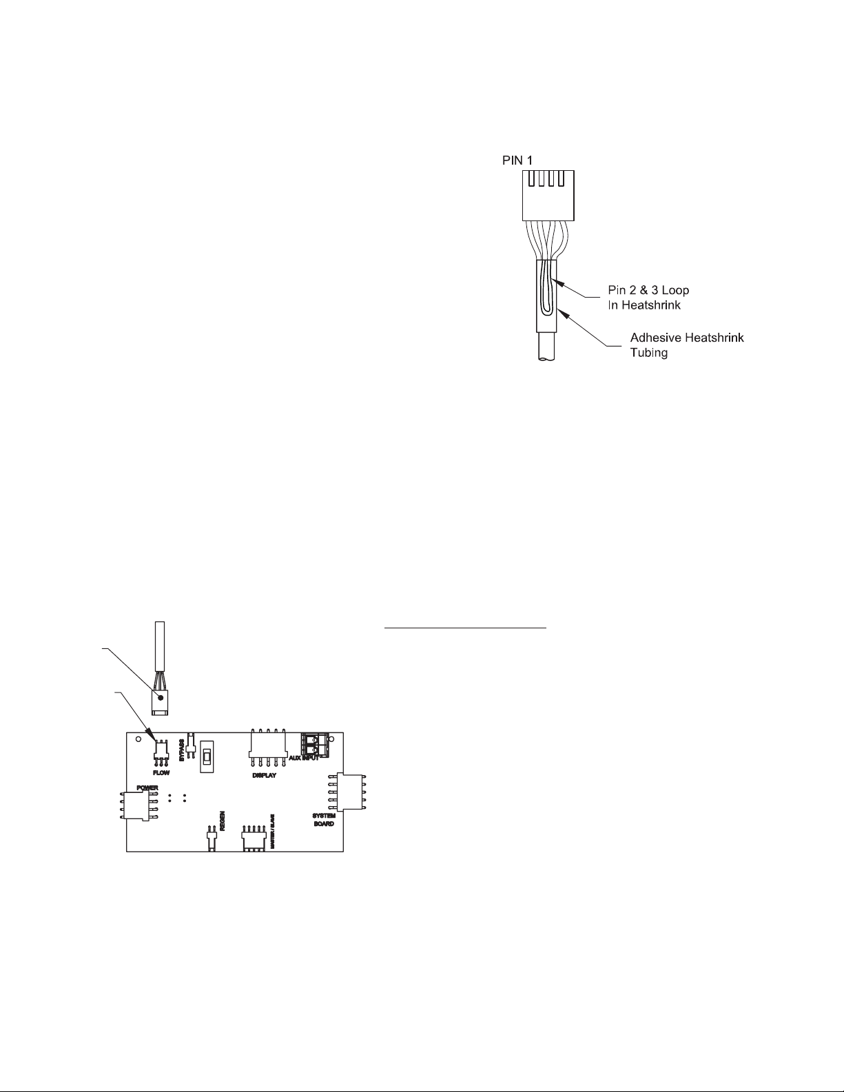
AC Adapter for European Use
1. 220-240 VAC 50Hz input, 24.0 VAC 750mA output.
2. Cable should be one unshielded pair of 22AWG, UV resistant
UL2464 compliant wire.
3. Connector details:
a. Terminate end with one Molex white housing,
P/N 09-50-8043 and four Molex pins, P/N 08-50-0108.
b. Pin 1 = 24.0 VAC White
Pin 2 = Jumper to Pin 3
Pin 3 = Jumper to Pin 2
Pin 4 = 24.0 VAC Black
Molex
Housing
Pin 1
Custom Meter Wiring:
1) Terminate end with a Molex series 2695 housing, part
number 22-01-3037 and (3) Molex series 41572 (or
40445) pins, part number 08-65-0805 (or 97-00-44).
2) Auxilliary meter must be able to operate on 5VDC
Pin 1 = +5VDC,
Pin 2 (Center) = Signal
Pin 3 = Ground
3) Acceptable pulse input is .1 – 999 pulses/gallon, or
.4 –519 pulses / liter.
WS2H Control Valve Manual Page 3
g
g
Separate
Relay 2 Output
Dry Contacts
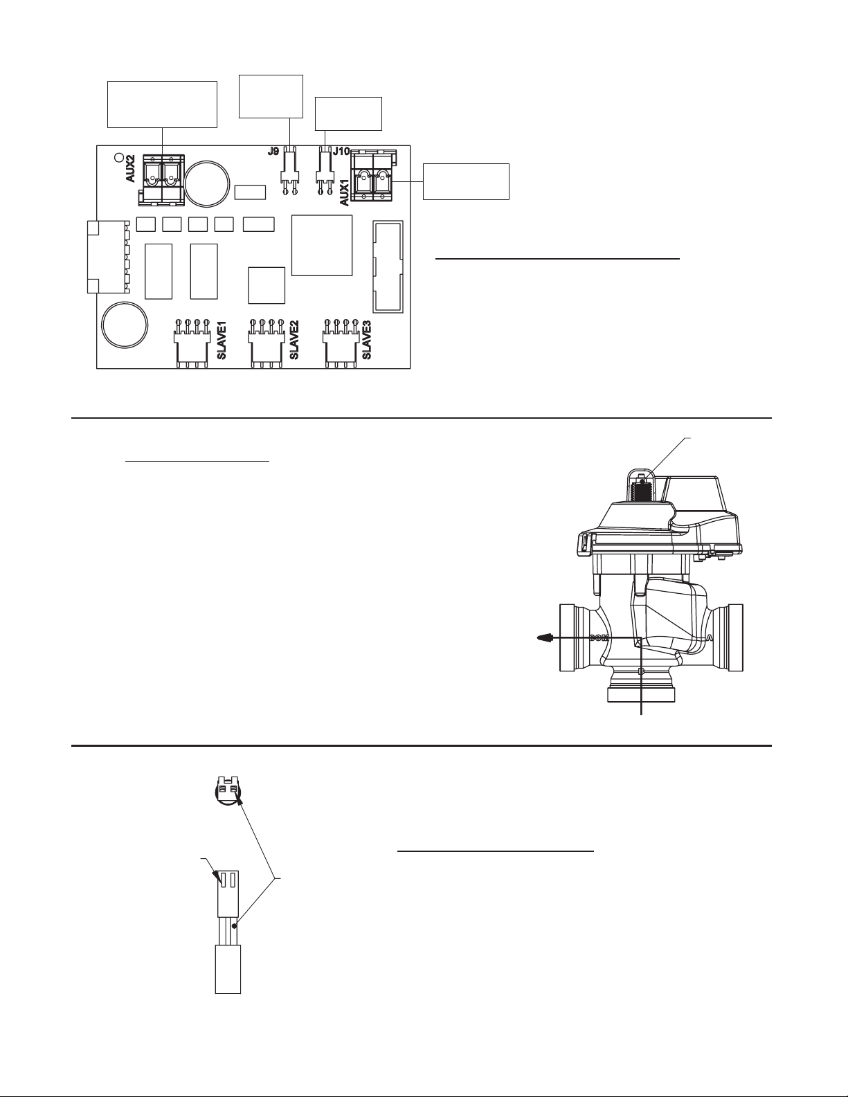
Motorized Drive Operation
Viewing the piston rod through the clear dome is a visual indicator of the
drives current positon. On the WS2 motorized bypass drive viewing the
rod indicates that the unit is in service. Viewing the rod as sho wn on the
MAV indicates that the common port is currently connected to the “B”
port. If the rod is not visible the unit is offline in the case of a bypass, or
connected to the “A” port of a MAV. This drive logic is reversible to meet
specific plumbing applications by reversing the polarity of the drive
motor wirin
harness as shown below.
Source Inlet
Motor Drive
Non
Functional
Relay 1 Output
Dry Contacts
Optional System Board, Required For
Relay Output And Separate Source Inlet
1) Relay outputs 1 & 2 are N.O. SPST dry contacts.
2) Maximum power through relays to be:
3) Separate source inlet drives require connection to a
a. 3A, 30 VDC
1A
1A
b. 3A, 30 VAC
V3063 or V3063BSPT motorized alternating valve
.
(MAV)
Piston Rod
Is Visible
Hold Locking Tab
While Pulling On Wire
Factory Wired
As White Wire
"Com" Port
Flow Path
Reversing Motorized Drive Direction
WS2 motorized bypass and MAV drives are factory wired with the white
wire on the right when viewing the wiring harness as shown, reversing
the wires reverses the logic of the drive. The wires can be removed
from the housing by holding down the locking tab in the small window
while applying light pressure to the wire, being careful not to disengage
the wire from its crimped on connector. The wires can then be reinserted, bein
sure the locking tab re-engages in the window.
"B" Port
"A" Port
Page 4 WS2H Control Valve Manual
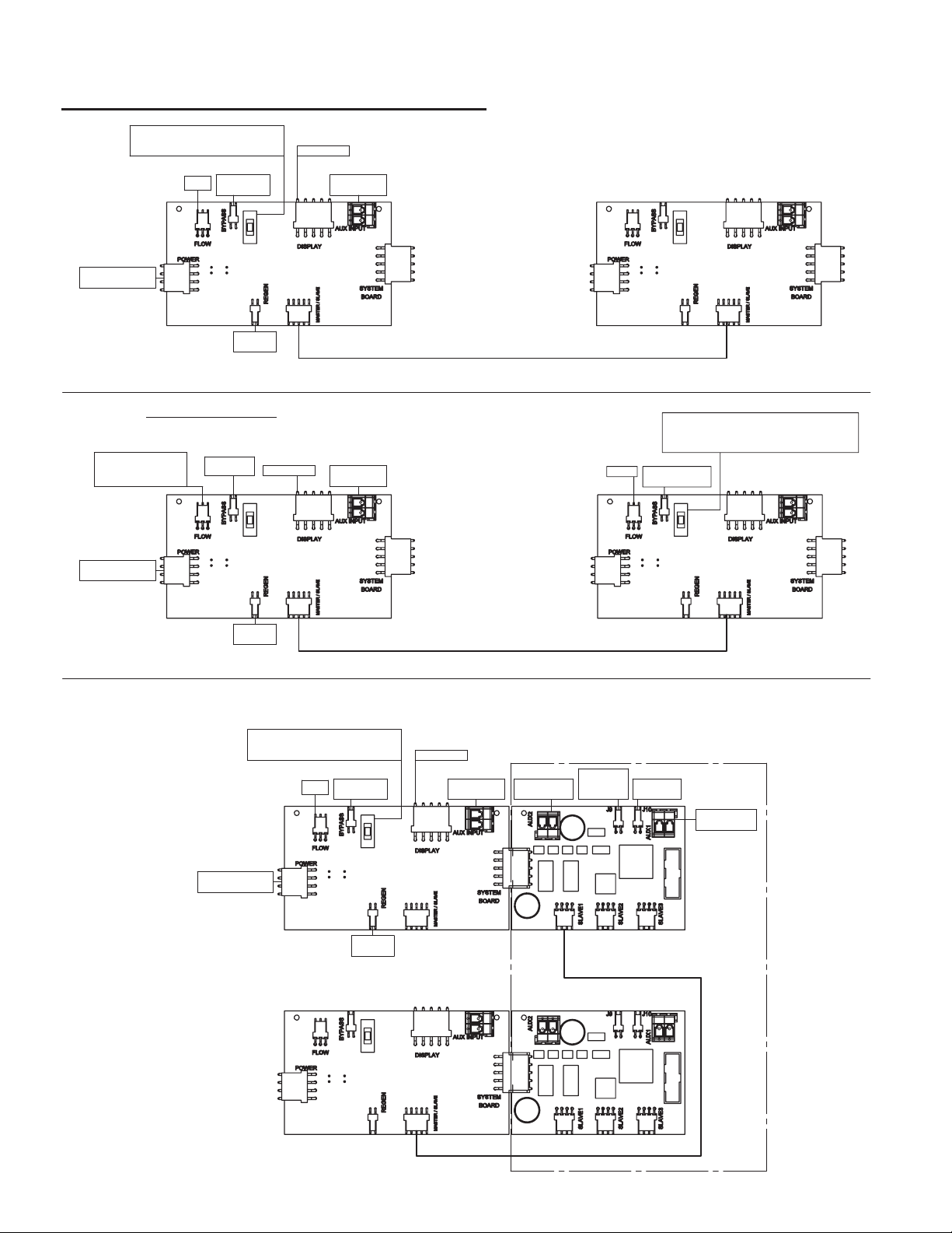
Wiring Diagram Examples, 2 Unit Systems
Motor Driven Bypass Manual Over Ride
Place in center for normal operation.
Up forces online, down forces offline
Transformer Power
(24 VAC)
Meter
Motor Driven
Bypass
Display Pod
Auxilliray (DP)
Switch Input
Two units, no system boards.
All Wiring Connections
Apply To Both Units
Unit 1 Unit 2
Simple Alternator
One Alternating Valve Replaces
Both Units Motorized Bypass
Meter; No Connection
If Both Units Are
Sharing A Single Meter
Transformer Power
(24 VAC)
Unit 1, Plumbed To
"A" Port On MAV
Main Drive
No
Connection
Main Drive
Motor
Motor
Display Pod
Auxilliray (DP)
Switch Input
Communication Cable
All Wiring Connections Apply To
Both Units. Connections For
Shared Meter And A MAV
Are Made On Unit 2 Only
Communication Cable
Motorized Alternating Valve Manual Over Ride
Up forces unit 2 online, down forces unit 1 online
Meter Motorized
Alternating Valve
Place in center for normal operation.
Unit 2, Plumbed To
Two unit system, with optional system boards
Motor Driven Bypass Manual Over Ride
Place in center for normal operation.
Up forces online, down forces offline
Motor Driven
Meter
Bypass
Display Pod
Auxilliray (DP)
for relay outputs and separate source inlet
Separate
Switch Input
Relay 2 Output
Dry Contacts
Source Inlet
Motor Drive
Non
Functional
Relay 1 Output
Dry Contacts
"B" Port On MAV
All Wiring Connections
Apply To Both Units
Transformer Power
(24 VAC)
Unit 1
Unit 2
Main Drive
Motor
Input On Slaves Must
Use Master / Slave Port
Communication Cable
WS2H Control Valve Manual Page 5
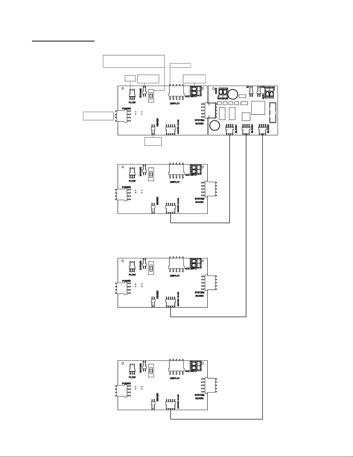
Wiring Diagrams
Transformer Power
Unit 1
All Wiring Connections
Apply To All Units
Motor Driven Bypass Manual Over Ride
Place in center for normal operation.
Up forces online, down forces offline
Meter
(24 VAC)
Motor Driven
Bypass
Main Drive
Motor
3 & 4 unit systems with no optional system boards
(4 unit shown)
Display Pod
Auxilliray (DP)
Switch Input
Communication
Cables
Unit 2
Unit 3
Unit 4
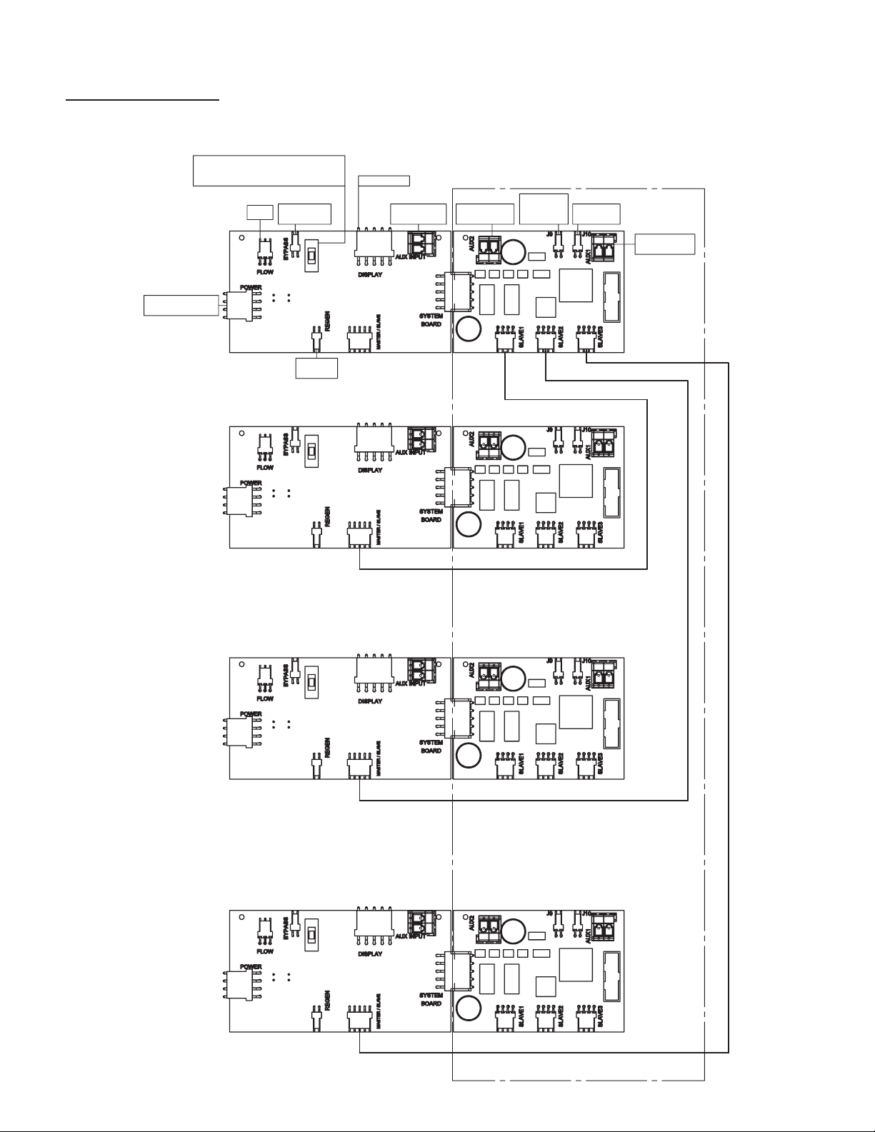
Page 6 WS2H Control Valve Manual
Wiring Diagrams
Motor Driven Bypass Manual Over Ride
Place in center for normal operation.
Up forces online, down forces offline
Transformer Power
(24 VAC)
Unit 1
All Wiring Connections
Apply To All Units
Meter
Motor Driven
Bypass
Main Drive
Motor
Display Pod
Auxilliray (DP)
Switch Input
3 & 4 unit systems with optional system boards
for relay outputs and separate source inlet
(4 unit shown)
Relay 2 Output
Dry Contacts
Separate
Source Inlet
Motor Drive
Non
Functional
Relay 1 Output
Dry Contacts
Communication
Cables
Unit 2
Unit 3
Input On Slaves Must
Use Master / Slave Port
Unit 4

WS2H Control Valve Manual Page 7

Page 8 WS2H Control Valve Manual
WS2H Control Valve Manual Page 9

Page 10 WS2H Control Valve Manual

WS2H Control Valve Manual Page 11
Typical User Screens
“REGEN TODAY” will
display when a regeneration
is scheduled, or fl ash for a
manually set regeneration.
“HOLD” or “START” REGEN
will fl ash in all user screens while
the auxiliary input is actuated.
USER 1
USER 1
Displays capacity remaining Does not
display if volumetric capacity is set to OFF.
Capacity remaining can be adjusted in 10 gallon
increments by holding the DOWN arrow for >3 seconds.
USER 2
USER 2
Displays days remaining Does not display if days
override is set to OFF.
Days remaining can be decremented one day at a
time by holding the DOWN arrow >3 seconds.
USER 3
USER 3
Displays time of day.
USER 4
USER 4
Displays the unit’s current fl ow rate.
USER 5
USER 6
USER 7
USER 5
Displays total unit volume since
install/reset Individually re-settable
using history reset sequence.
USER 6
Displays the current system fl ow rate
Does not display on single tank units.
USER 7
Displays total system volume since install/reset
Individually re-settable using history reset sequence
Does not display on single tank units.
User 1

Page 12 WS2H Control Valve Manual
Setting Time of Day
SET TIME
Accessed by pressing Set Clock while in the
User Screens. Use UP and DOWN arrows to
scroll hours. AM/PM alternates at midnight.
Return to
Normal Operation
UNIT COUNT ERROR
Error and the slave’s unit number will fl ash when it is
not detected. Pressing any button will return the user
to the #units set up screen to correct the value.
ERROR SCREEN
Error and its code alternate. The unit returns to home
and fl ashes its 3 LEDs. The unit continues to try and
function, but must be reset to correct the error screen.
Automatically toggles.

WS2H Control Valve Manual Page 13
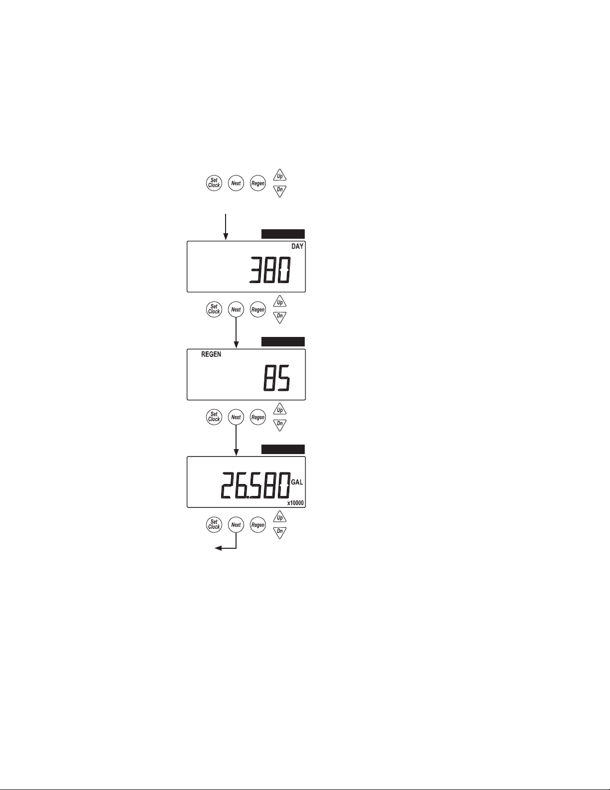
Installer Setup Screens
Accessed by pressing NEXT and
UP simultaneously for >3 seconds.
Set current day and regen days
when set as a 7 day time clock
or hybrid in System Setup 1.
INSTALLER 1
INSTALLER 2 INSTALLER 2
INSTALLER 3
Returns to normal operation after 5 minutes.
INSTALLER 1
Set volumetric capacity or OFF. OFF will not be an
option if the day control is set to OFF.
X1000 Indicator Illuminates At 10,000 Gallons
Units Range Increments
US
(GAL)
SI
(L)
INSTALLER 2
Set day override. 1-28 days between regenerations, or if set to
7 day time clock, see 7 day setup below. OFF will display if
selected in Day Control screen.
INSTALLER 3
Select time of regen. Use up and down arrows to scroll
hours. AM/PM alternates at midnight. “on0” will be
displayed on units with no time dependent regen control.
(“1” only shows if set for multiple regens.)
10-10,000
10,000-100.00 x 1000
100.00-999.00 x 1000
38-38,000
38,000-380.00 x 1000
380.00-3796.2 x 1000
10
100
1000
38
38
3800
Return To
Normal Operation.
INSTALLER 4
7 Day Option
INSTALLER 2
INSTALLER 2B
INSTALLER 2C
INSTALLER 4
Select time of regen. Use up and
down arrows to scroll minutes.
INSTALLER 5
INSTALLER 5
Select time of 2nd regen
(if confi gured as a multiple
regenerating unit.)
INSTALLER 2
7 day time clock option.
Set current day of the week:
1 = Sunday
2 = Monday
3 = Tuesday
4 = Wednesday
5 = Thursday
6 = Friday
7 = Saturday
INSTALLER 2B
Scroll through days 1-7 using the UP and DOWN arrows.
Pressing the Set Clock will toggle regen ON or OFF for
that day. (i.e., regen on Monday.)
INSTALLER 2C
(i.e., no regeneration on Saturday.)
Installer 3

Page 14 WS2H Control Valve Manual
System Setup Screens
Returns to normal operation after 5 minutes
Accessed by pressing NEXT and DOWN
simultaneously for >3 seconds.
SYSTEM SETUP 1
SYSTEM SETUP 1
Select country.
US or SI.
This sets the use of a 12 or 24 hour clock
and the display of gallons or liters.
SYSTEM SETUP 2
SYSTEM SETUP 2
Select the total number of units, from 1-4, in a
system. This screen will only allow 1 or 2 if a
system board is not installed.
SYSTEM SETUP 3
SYSTEM SETUP 4
SYSTEM SETUP 5
SYSTEM SETUP 3
Select unit fl ow rate unit add point.
1. If set to 0, all units are online unless one is regenerating.
2. If greater than 0, the system acts as a stage by fl ow adding units as fl ow
capacity increases.
3. If set to ALT the system acts as an alternator
system, keeping one unit off line at all times.
The screen will not display if set to 1 unit.
SYSTEM SETUP 4
Single units have a selection of hard water bypass, no hard water bypass or relay operation.
When the units starts a regen, HbP will allow hard water bypass, noHbp and RELAY
will not allow hard water bypass. Systems will allow setting noHbP or RELAY & 2 unit
alternators have an additional selection of ALT-A. Setting noHbP requires a motor driven
bypass, ALT-A requires a motor driven alternator valve on the controlling unit and RELAY
relys on external valving for noHbP control.
SYSTEM SETUP 5
Select day control type.
Time clock 1-28 day; Time clock 7 day; or OFF.
When volumetric capacity is set, volume regeneration can
be combined with time clock control. OFF will not be an
option if volumetric capacity is OFF.
Units Range Increments
US
SI
(L)
0-500 1
0-1896 4
(GAL)
continued on Page 15
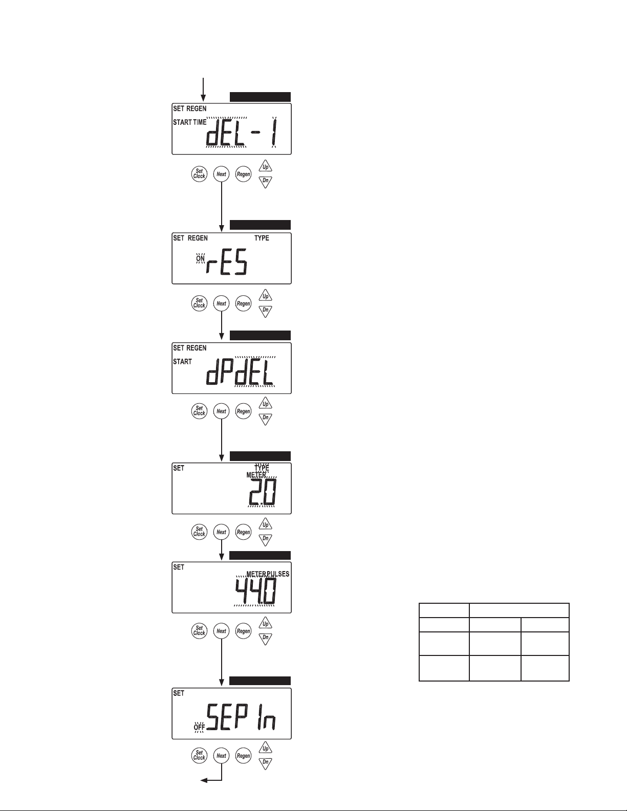
WS2H Control Valve Manual Page 15
System Setup Screens (continued)
SYSTEM SETUP 6
SYSTEM SETUP 7
SYSTEM SETUP 8
SYSTEM SETUP 6
Select regeneration type.
Delayed (dEL-1)
Delayed, 2 regenerations per day (dEL-2)
Delayed, 3 regenerations per day (dEL-3)
Delayed, 4 regenerations per day (dEL-4)
On 0
Delayed with multiple regenerations allowed per day would be
used either to reduce the reserve volume, or to accommodate a
small system relative to the treatment demand.
SYSTEM SETUP 7
Select reserve calculation ON or OFF.
OFF will schedule a regen when the volumetric
capacity reaches 0. This screen will not display
for “on0” units or systems.
SYSTEM SETUP 8
Set auxiliary initiated regen.
START TIME REGEN: regeneration will start immediately after 2 cumulative
minutes of switch closure.
START TIME REGEN dEL: regeneration will start at the delayed time after 2
cumulative minutes of switch closure.
START REGEN: regeneration will start immediately upon switch closure.
START REGEN dEL: regeneration will start at the delayed time upon switch closure.
HOLD REGEN: regeneration will not be allowed as long as there is switch closure.
SYSTEM SETUP 9
SYSTEM SETUP 9B
SYSTEM SETUP 10
SYSTEM SETUP 9
Select meter type or pulses.
2.0 meter (type)
1.5 meter (type)
System Pulses
SYSTEM SETUP 9B
Select meter type pulses.
Screen does not show if Pulses or System Pulses is not
selected in the previous screen.
Units Range Increments
US
(Pulse/Gal)
SI (Pulse/L)
0.1 - 30.0
30.0 - 999.0
0.4 - 114.0
114.0 - 519.4
SYSTEM SETUP 10
Separate source inlet. This screen will not
display if a system board is not installed.
Pulses/ Unit Flow
0.1
1.0
0.4
3.8
Return To
Normal Operation
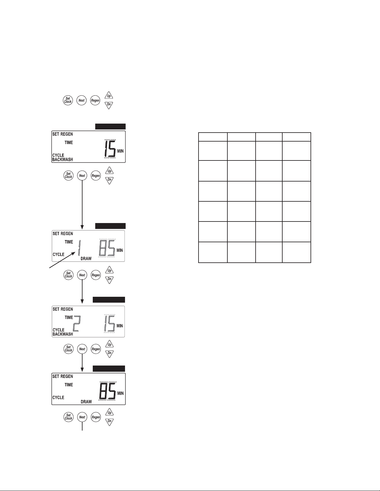
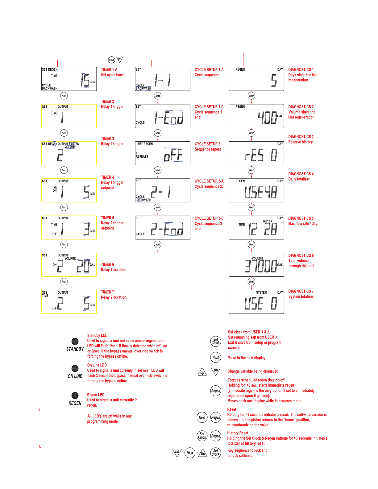
Page 16 WS2H Control Valve Manual
Timer Screens
Returns to normal operation after 5 minutes.
Accessed by pressing NEXT and DOWN simultaneously
for >3 seconds, then by pressing NEXT and DOWN
simultaneously again for >3 seconds.
“1” is displayed if
set for more than
one sequence
TIMER 1-A
TIMER 1-B
TIMER 1-A2
TIMER 1-A
Select time of cycle 1.
A NEXT & DN reset from
this screen unlocks the
setup screens.
TIMER 1-B
Select time of cycle 2.
The following screens only show if the unit is
programmed for multiple regenerations in the
Cycle Setup 2 screen.
TIMER 1-A2
Select time of alternate regen, cycle 1.
Cycle Units Range Increments
Backwash Minutes
Draw Minutes
Slow Rinse Minutes
Rinse Minutes
Fill Minutes
Hold Minutes
1-30
30-95
1-30
30-100
100-180
1-30
30-95
1-30
30-95
0.1-10.0
10.0-30.0
30.0-99.0
1-30
30-100
100-480
1
5
1
5
10
1
5
1
5
0.1
0.2
1.0
0.1
2.0
10.0
TIMER 1-B2
TIMER 1-B2
Select time of alternate regen, cycle 2.
continued on Page 17
WS2H Control Valve Manual Page 17
Timer Screens (continued)
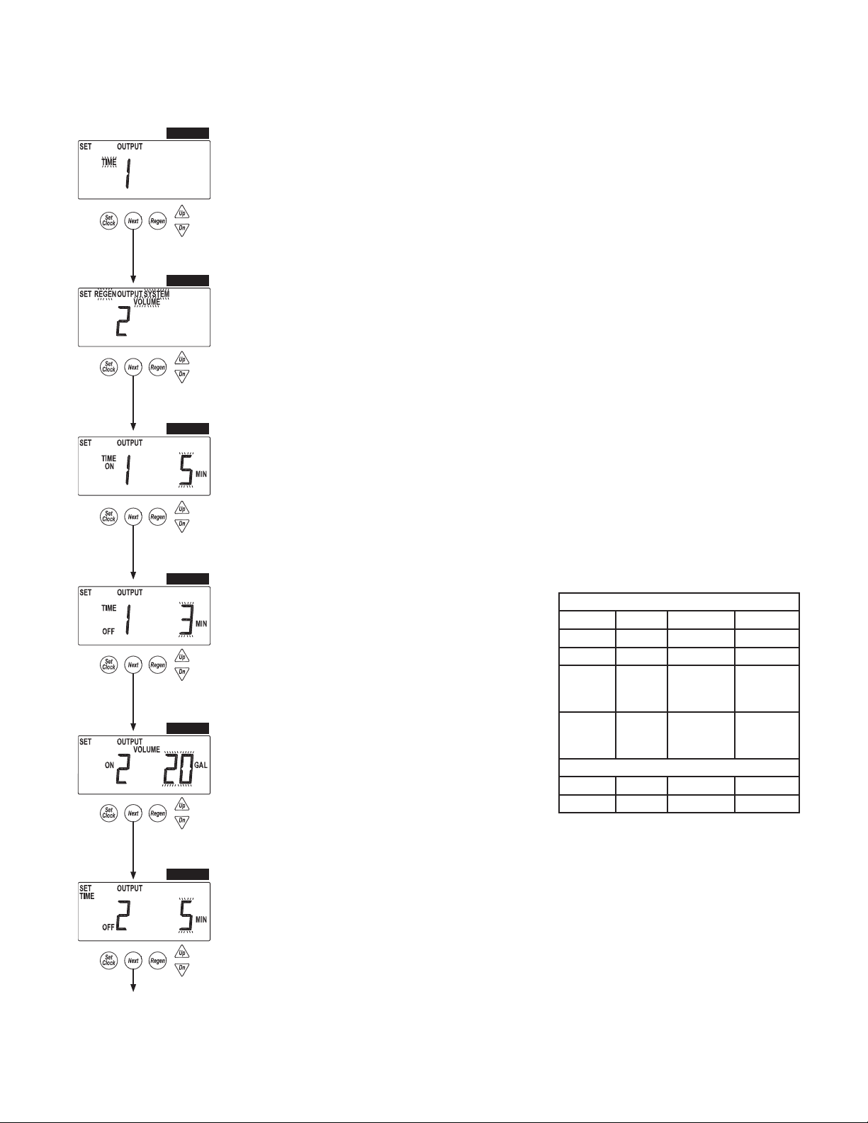
TIMER 2
TIMER 2
TIMER 2
Set output 1.
These settings will only be allowed with the system board installed.
Time: Relay is turned on after specifi ed time from the start of regen and is left on for a specifi ed time.
Cycle: Relay is turned on after the start of a specifi ed cycle and is left on for a specifi ed time.
Volume: Relay is turned on, during service fl ow only, every specifi ed number of volume units and is left on for a specifi ed time.
Volume & Regen: Relay is turned on every specifi ed number of volume units, and is left on for a specifi ed time.
STbY: Relay would be used to control external valving, closing for unit regeneration, or when it would be offl ine in system operation.
REGEN: Relay closes when the unit is in regen.
Err: Relay closes when the unit is in any error mode.
TIMER 3
TIMER 4
TIMER 5
TIMER 6
TIMER 3
Set output 2.
These settings will only be allowed with the system board installed.
Time: Relay is turned on after specifi ed time from the start of regen and is left on for a specifi ed time.
Cycle: Relay is turned on after the start of a specifi ed cycle and is left on for a specifi ed time.
Volume: Relay is turned on, during service fl ow only, every specifi ed number of volume units and is left on for a specifi ed time.
Volume & Regen: Relay is turned on every specifi ed number of volume units and is left on for a specifi ed time.
STbY: Relay would be used to control external valving, closing for unit regeneration, or when it would be offl ine in system operation.
REGEN: Relay closes when the unit is in regen.
Err: Relay closes when the unit is in any error mode.
TIMER 4
Select output 1, On trigger set point, per units previously selected.
This screen will not display if the unit does not have a system board, or if STbY was selected as the trigger.
Time: Time after the start of a regen before switch is closed.
Cycle: Select a cycle which will close output 1.
Volume: Volume of water interval during service between switch closures.
Timer 4 and 6 screens will not display if display if STbY, REGEN or Err are selected in TIMER 2 and TIMER 3.
TIMER 5
Select output 1 On duration before turning OFF. This screen will
not display if the unit does not have a system board.
TIMER 6
Select output 2, On trigger set point, per units previously selected.
This screen will not display if the unit does not have a system board, or if
STby was selected as the trigger
Time: Time after the start of a regen before switch is closed.
Cycle: Select a cycle which will close output 2.
Volume: Volume of water interval during service between switch closures.
Trigger Units Range Increments
Time Minutes :01-20:00 :01
Cycle Slow Rinse
Volume Gallons
Volume Liters
Trigger Units Range Increments
Time Minutes :01-20:00 :01
Relay Trigger Settings
1-200
200-1000
100-10000
1-760
760-13800
13800-38000
Relay Duration Settings
1
5
10
4
19
38
Return To
Normal Operation.
TIMER 7
TIMER 7
Select output 2 On duration before turning OFF.
This screen will not display if the unit does not have a
system board.
Page 18 WS2H Control Valve Manual
Cycle Setup Screens
Returns to normal operation after 5 minutes.
Accessed by pressing NEXT and DOWN simultaneously for >3 seconds,
then by pressing NEXT and DOWN simultaneously again for >3 seconds,
then by pressing NEXT and DOWN simultaneously for >3 seconds a third time.
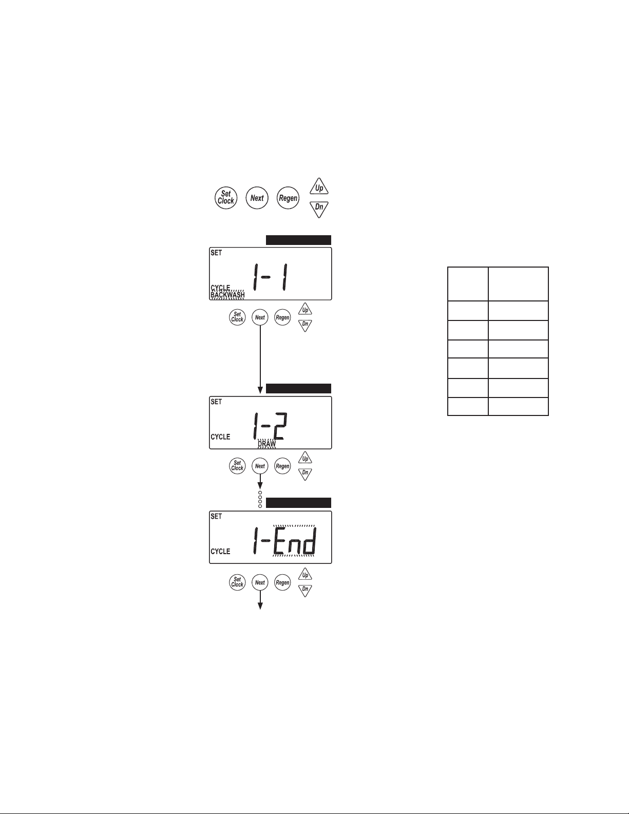
CYCLE SETUP 1-A
CYCLE SETUP 1-A
Select fi rst cycle.
CYCLE SETUP 1-B
CYCLE SETUP 1-C
Cycle #
1 Backwash
2 Draw
3 2nd Backwash
4 Rinse
5 Fill
CYCLE SETUP 1-B
Select second cycle.
CYCLE SETUP 1-C
After cycles are confi gured, an END is added.
(9 cycles maximum.)
6 End
Cycle
Default
continued on Page 19

WS2H Control Valve Manual Page 19
Cycle Setup Screens (continued)
CYCLE SETUP 2
CYCLE SETUP 3-A
CYCLE SETUP 3-B
CYCLE SETUP 2
Select regeneration repeats, 1-10 or OFF.
Repeats regeneration cycle sequence 1 a selected number
of times before regenerating a single time with sequence 2.
The following screens only show if the unit is
programmed for multiple regenerations in the
previous screen.
CYCLE SETUP 3-A
Select fi rst cycle of “alternate”
regeneration sequence.
CYCLE SETUP 3-B
Select second cycle of ‘alternate’
regeneration sequence.
Return To
Normal Operation
CYCLE SETUP 3-C
CYCLE SETUP 3-C
After cycles are confi gured, an END is added.
(9 cycles maximum.)
Page 20 WS2H Control Valve Manual
Diagnostic Screens
Accessed by pressing UP and DOWN
simultaneously for >3 seconds.
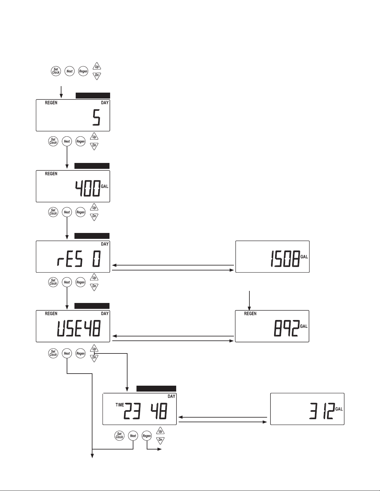
DIAGNOSTIC 1
DIAGNOSTIC 2
DIAGNOSTIC 3
Returns to normal operation after 5 minutes.
DIAGNOSTICS 1
Days since the last regeneration.
DIAGNOSTICS 2
Gallons or Liters x1000 since the last
regeneration.
DIAGNOSTICS 3
Reserve history. This screen only appears if valve
is set to calculate Reserve in System Setup 7.
Use arrows to select a day.
0 = Today
1 = Yesterday
6 = 6 days ago (max.)
All Diagnostic History screens are resettable
with the History Reset sequence while in the
Diagnostics1 screen. Holding the Set Clock
and Regen buttons for > 3 seconds initiates a
totalizer or history reset.
Reserve Value
DIAGNOSTIC 4
Automatically T oggles
DIAGNOSTICS 4
History of volume used.
Use arrows to select a day.
0 = Today
1 = Yesterday
63 = 63 days ago (max.)
Automatically T oggles
Simultaneously press
UP and DOWN.
DIAGNOSTIC 4-B
Diagnostic 4
REGEN will display if a
regeneration occurred that day.
DIAGNOSTICS 4-B
Hourly history of volume use. Use
the UP and DOWN arrow to select
the hours of the day from screen 4.
Automatically T oggles
Gallons Used
Volume used within the selected hour
continuned on Page 21
WS2H Control Valve Manual Page 21
Diagnostic Screens (continued)
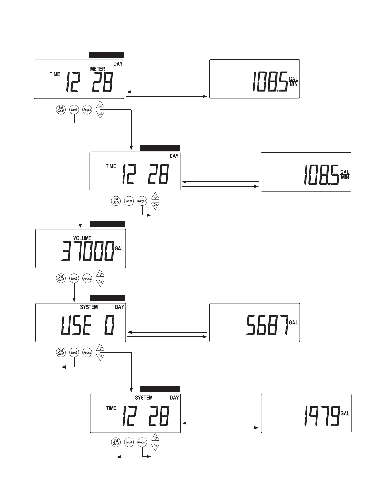
DIAGNOSTIC 5
DIAGNOSTIC 6
DIAGNOSTICS 5
Maximum fl ow rate
for the last 28 days.
Automatically T oggles
Simultaneously press
UP and DOWN.
DIAGNOSTIC 5-B
Diagnostics 5
DIAGNOSTICS 6
Total volume through the unit.
Max fl ow rate of the day
DIAGNOSTICS 5-B
Hourly history of maximum
fl ow rate. Use the UP and
DOWN arrow to select the
hours of the day from screen 5.
Automatically T oggles
Max fl ow within the selected hour
Return To
Normal Operation
DIAGNOSTIC 7
Return To
Normal Operation
DIAGNOSTICS 7
System totalizer for the last
63 days. Only displays in a
master unit.
Automatically T oggles
Simultaneously press
UP and DOWN.
DIAGNOSTIC 7-B
Diagnostics 7
System use for that day
DIAGNOSTICS 7-B
Hourly system totalizer. Use
the UP and DOWN arrow to
select the hour of the day from
screen 7.
Automatically T oggles
Total system fl ow for the selected hour
Page 22 WS2H Control Valve Manual
Valve History
Returns to normal operation after 5 minutes.
Non-Resettable
Accessed by pressing UP and DOWN simultaneously
for >3 seconds, then by pressing UP and DOWN
simultaneously again for >3 seconds.
HISTORY 1
HISTORY 1
Total days since startup.
Time only accumulates while
the unit is plugged in.
Return To
Normal Operation
HISTORY 2
HISTORY 2
Total regenerations since startup.
HISTORY 3
HISTORY 3
Total volume since startup.

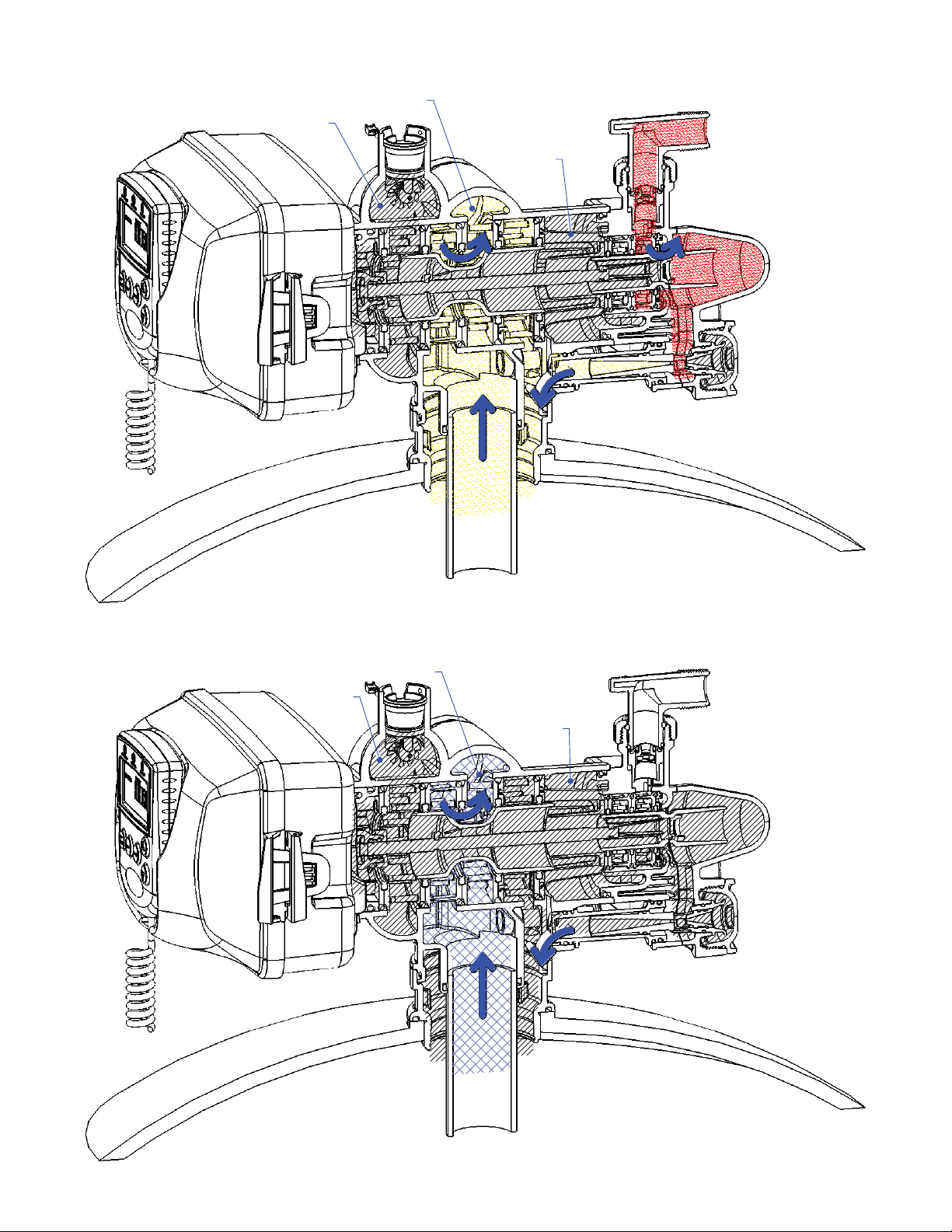
WS2H Control Valve Manual Page 23
Treated Water
Supply
Raw Water
Inlet
Hard Water
Supply
Service
To Drain
Raw Water
Inlet
Backwash
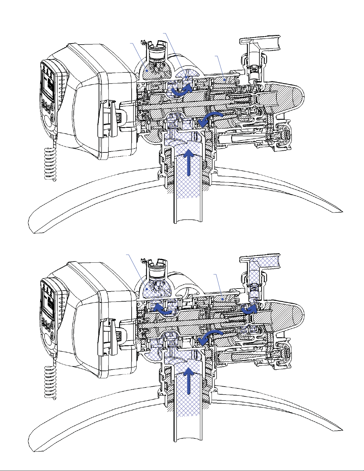
Page 24 WS2H Control Valve Manual
Hard Water
Supply
To Drain
Solution Is
Drawn In
Raw Water
Inlet
Hard Water
Supply
Draw
To Drain
Raw Water
Inlet
Slow Rinse
WS2H Control Valve Manual Page 25
To Drai
Hard Water
Supply
n
Raw Water
Inlet
Treated Water
Supply
Raw Water
Inlet
Rinse
Treated Water
To Tank
Softwater Fill

Page 26 WS2H Control Valve Manual
Front Cover and Drive Assembly
Drawing No. Order No. Description Quantity
1 V3068 WS2 POD ASY 1
2 V3241-01 WS2 PC BOARD DISPLAY 1
3 V3248 WS2 CABLE DISPLAY POD 1
4 V3242-01 WS2 PC BOARD VALVE 1
5 V3224-01R WS2 COVER ASY PLATINUM 1
6 V3107-01 WS1 MOTOR ASY 1
7 V3226-01 WS2 DRIVE BRACKET ASY 1
8 V3110 WS1 DRIVE GEAR 12X36 3
9 V3109 WS1 DRIVE GEAR COVER 1
Not Shown V3461 WS2 AC ADAPTER 24V
1Not Shown V3461EU WS2 AC ADAPTER 24V EU
Not Shown V3461UK WS2 AC ADAPTER 24V UK
10 V3243-01 WS2 PC BOARD SYSTEM Optional
Not Shown V3475-12 WS2 SYS CONNECT CORD 12 FT RED Optional
Not Shown V3475-24 WS2 SYS CONNECT CORD 24 FT BL Optional
Not Shown V3475-36 WS2 SYS CONNECT CORD 36 FT YEL Optional
5
1
7
8
2
3
9
4
6
10
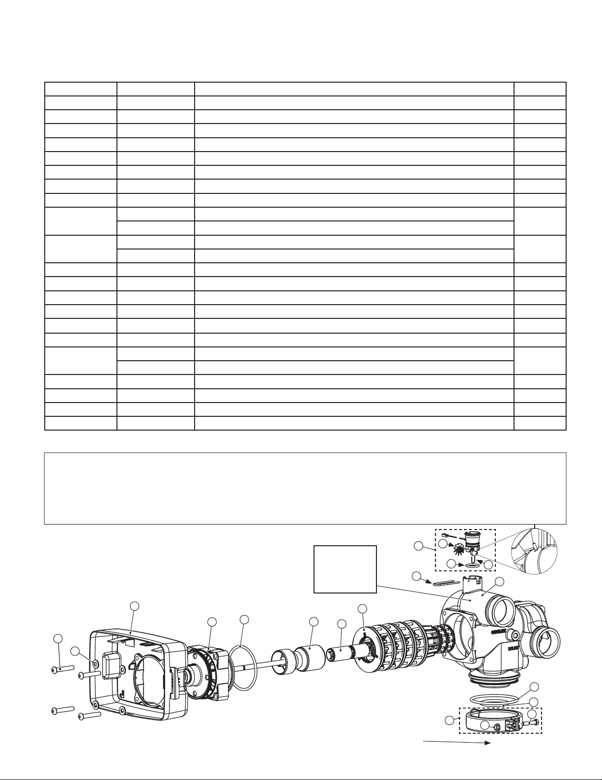
WS2H Control Valve Manual Page 27
Drive Cap Assembly, Downfl ow Piston, Regenerant Piston, Spacer Stack Assembly, Drive Back Plate,
Main Body and Meter
Drawing No. Order No. Description Quantity
1 V3274 WS2 SCREW BTNSKT HD SS3/8-16X2 4
2 V3291 WS2 WASHER SS 3/8 4
3 V3225 WS2 BACK PLATE 1
4 V3066 WS2 DRIVE ASY 1
5 V3289 O-RING 344 1
6 V3204-01 WS2 PISTON 1
7 V3238-01 WS2 BRINE PISTON 1
8 V3065 WS2 STACK ASY 1
Not Shown
9
10 V3223 WS15/WS2 METER CLIP 1
11 V3003-02 WS1.5/2H METER COMMERCIAL ASY 1
12 V3118-03 WS1.5/2 TURBINE ASY 1
13 V3105 O-RING 215 1
14 V3501
15 V3279 O-RING 346 1
16
17 V3054** WS2 4 IN BASE CLAMP ASY 1
18 V3276 WS2 BOLT HEX SS 5/16-18X1-3/4 1
19 V3269 WS2 NUT 5/16-18 SS HEX 1
Not Shown D1300-01 TOP BAFFLE DFSR CLACK 2/63MM 1
**V3054 WS2 4 IN BASE CLAMP ASY includes a V3276 WS2 BOLT HEX SS 5/16-18X1-3/4 and V3269 WS2 NUT 5/16-18 SS HEX.
V3468 WS2 PLUG 1/4 HEX NPT (included when ordering V3201-03)
V3465 WS2 PLUG 1/4 HEX BSPT (included when ordering V3201BSPT-03)
V3201-03 WS2 BODY W/V3468 PLUG
V3201BSPT-03 WS2 BSPT BODY W/V3465 PLUG
WS1.5/2 TURBINE CLIP
V3280 O-RING 332 FOR VALVE BODIES WITH NPT THREADS
V3452 O-RING 230 FOR VALVE BODIES WITH BSPT THREADS
2
1
1
1
In 2007, a u-shaped retaining clip (V3501) was added to commercial meter assemblies to hold the turbine assembly in place. If V3501 is present, service or replace
the turbine by:
1. Removing bend from the two exposed tips of the retaining clip and remove clip.
2. Service or replace the V3118-03 WS1.5/2 Turbine Assembly and place back on the turbine shaft.
3. Insert the V3501 WS1.5/2 Turbine Clip and rebend the exposed tips.
The V3118-03 has a groove to line up with the V3501 WS1.5/2 Turbine Clip. If the meter assembly does not have two holes in the bottom to insert the clip, use a
V3118-01 Turbine Assembly or replace the entire meter.
12
B or indent
indicates BSPT
N or no mark
indicates NPT
3
4
1
2
Install D1300-01 upper diffuser (not shown) when using the 4” Quick Dissconnect (V3064)
5
6
8
7
11
13
10
17
14
9
15
16
18
19
Page 28 WS2H Control Valve Manual
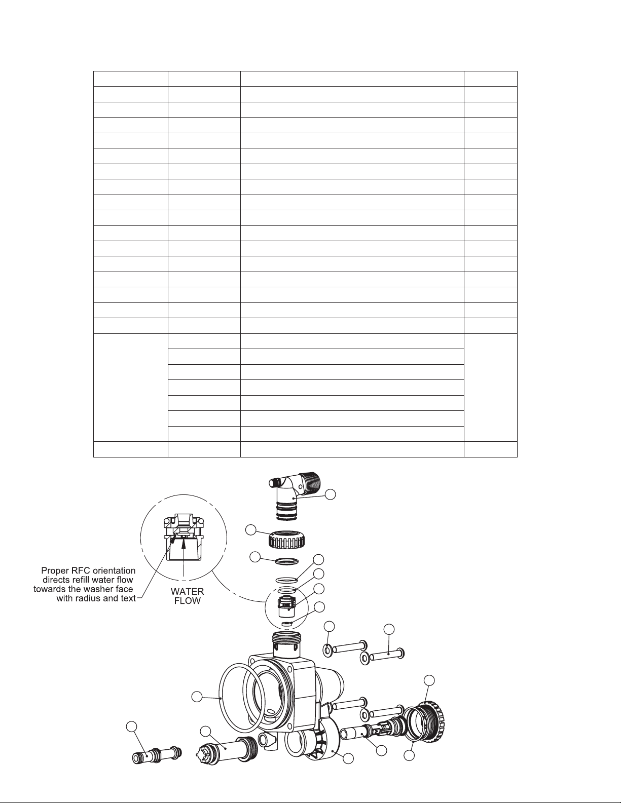
Brine Valve Body and Injector Components
Drawing No. Order No. Description Quantity
1 V3237-01 WS2 SOFTFILL TUBE ASY 1
2 V3236-01 WS2 INJECTOR TUBE ASY 1
3 V3289 O-RING 344 1
4 V3067 WS2 BRINE BODY ASY 1
5 V3477 WS2 INJECTOR CAP 1
6 V3152 O-RING 135 1
7 V3275 WS2 SCREW BSHD SS 3/8-16X2-1/4 4
8 V3291 WS2 WASHER SS 3/8 4
9 V3162-022* WS1 DLFC 022 FOR 3/4 1
10 V3231 WS2 REFILL FLOW CNTRL RETAINER 1
11 V3277 O-RING 211 1
12 V3105 O-RING 215 1
13 V3150 WS1 SPLIT RING 1
14 V3151 WS1 NUT 1 QC 1
15 V3149 WS1 FTG 1 PVC MALE NPT ELBOW 1
Not Shown V3189 WS1 FTG 3/4&1 PVC SLVNT 90 Optional
V3010-2A WS2 INJECTOR ASY A
V3010-2B WS2 INJECTOR ASY B
V3010-2C WS2 INJECTOR ASY C
16
Not Shown V3499** WS2 FITTING CAP 1 IN THREADED 1
V3010-2D WS2 INJECTOR ASY D
V3010-2E WS2 INJECTOR ASY E
V3010-2F WS2 INJECTOR ASY F
V3010-2G WS2 INJECTOR ASY G
1
*Any V3162-XXX fl ow control may be used.
V3237-01 WS2 SOFTFILL TUBE ASY contains a
15
14
13
3
1
2
12
11
10
9
8
V3155 O-RING 112, V3287 O-RING 110 and a V3288
O-RING 206.
V3236-01 WS2 INJECTOR TUBE ASY contains a
V3285 O-RING 213 and a V3286 O-RING 216.
V3010-2X injectors contains a V3283 O-RING 117 and
a V3284 O-RING 114.
** Install V3499 on V3149 if valve is to be set up as a
backwash only valve
7
5
16
4
6

WS2H Control Valve Manual Page 29
V3064 WS2H/2L 4 INCH BASE ASY
Drawing No. Order No. Description Quantity
1
2 V3281 O-RING 348 1
1 V3202-01 WS2 BASE 1
2
V3055 WS2H/2L FLANGE BASE ASY
Drawing No. Order No. Description Quantity
1
1 V3444 WS2 SCREW HEXCAP 5/16-18X2.5SS 12
2 V3293 WS2 WASHER SS 5/16 FLAT 24
2
6
3
4
5
3 V3445 WS2 WASHER SPLIT LOCK 5/16 SS 12
4 V3447 WS2 NUT HEX 5/16-8 FULL SS 12
5 COR60FL O RING 6 FLANGE ADAPTER(PARK) 1
6 V3261-01 WS2 FLANGE BASE 1
V3260-02 WS2 SIDE MOUNT BASE NPT
V3260BSPT-02 WS2 SIDE MOUNT BASE BSPT ASY
1
Drawing No. Order No. Description Quantity
1 V3280 O-RING 332 1
2 V3260BSPT-01 WS2 SIDE MOUNT BASE BSPT 1
When using a side mount base with 2H BSPT valves replace distributor
pilot o-ring V3452 O-RING 230 with V3280 O-RING 332. See
exploded view of 2H valve in WS2H manual for specifi c location of
2
distributor pilot o-ring.

Page 30 WS2H Control Valve Manual
Washer
Radius
Direction
Of Flow
Direction
Of Flow
1
V3051 WS2 DLFC ASY NPT and V3051BSPT WS2 DLFC ASY BSPT
Drawing No. Order No. Description Quantity
1 V3052 WS2 DLFC Retainer ASY 1
2
3
4 V3273 BOLT HEX HD S/S HCS 3/8-16X3/4 4
5 V3278 O-ring 338 1
Not Shown
Assemblies are shipped without drain line fl ow control (DLFC). Assembly instructions:
1. Determine the desired fl owrate. Select a combination of V3162-XXX’s and V3190-XXX’s to arrive at the desired fl ow rate. Up to fi ve of the
smaller V3162-XXX’s may be used. Up to four of the larger V3190-XXX’s may be used.
2. Using a drill or punch remove the desired knockout(s) in V3052.
3. Smooth hole(s).
4. Install appropriate size(s) of drain line fl ow control washers. Pay close attention to proper DLFC orientation.
5. Assemble. Properly orientate the V3052 in the direction of fl ow.
6. Inlet and outlet threads are 2” NPT. Couplings for iron pipe may also be used.
V3245 WS2 DLFC FLANGE INLET NPT
V3245BSPT WS2 DLFC FLANGE INLET BSPT
V3246 WS2 DLFC FLANGE OUTLET NPT
V3246BSPT WS2 DLFC FLANGE OUTLET BSPT
V3162-007 WS1 DLFC 0.7 gpm for 3/4
V3162-010 WS1 DLFC 1.0 gpm for 3/4
V3162-013 WS1 DLFC 1.3 gpm for 3/4
V3162-017 WS1 DLFC 1.7 gpm for 3/4
V3162-022 WS1 DLFC 2.2 gpm for 3/4
V3162-027 WS1 DLFC 2.7 gpm for ¾
V3162-032 WS1 DLFC 3.2 f gpm or 3/4
V3162-042 WS1 DLFC 4.2 gpm for 3/4
V3162-053 WS1 DLFC 5.3 gpm for 3/4
V3162-065 WS1 DLFC 6.5 gpm for 3/4
V3162-075 WS1 DLFC 7.5 gpm for 3/4
V3162-090 WS1 DLFC 9.0 gpm for 3/4
V3162-100 WS1 DLFC 10.0 gpm for 3/4
V3190-090 WS1 DLFC 9.0 gpm for 1
V3190-100 WS1 DLFC 10.0 gpm for 1
V3190-110 WS1 DLFC 11.0 gpm for 1
V3190-130 WS1 DLFC 13.0 gpm for 1
V3190-150 WS1 DLFC 15.0 gpm for 1
V3190-170 WS1 DLFC 17.0 gpm for 1
V3190-200 WS1 DLFC 20.0 gpm for 1
V3190-250 WS1 DLFC 25.0 gpm for 1
1
1
Install One or
More DLFC’s.
Up to 5 of
the V3162-
XXX may be
installed in the
small holes.
Up to 4 of
the V3190-
XXX may be
installed in the
large holes.
4
3
B indictates BSPT
N indicates NPT
2
5
1

WS2H Control Valve Manual Page 31
V3060 WS2 BYPASS AUTO NPT, V3060BSPT WS2 BYPASS AUTO BSPT,
V3061BSPT WS2 BYPASS MANUAL BSPT and V3061 WS2 BYPASS MANUAL NPT
Drawing No. Order No. Description
1 V3056 WS1.5&2AL T/2BYPASS AUTO CVRASY 1 N/A
2 V3476 WS MOTOR ASY 8 FT 1 N/A
3 V3272 WS2 SCREW 8X1 SS HEX SELF TAP 3 N/A
4 V3262-01 WS1.5&2ALT/2BY REDUCGEARCVRASY 1 N/A
5 V3110 WS1 DRIVE GEAR 12X36 3 N/A
6 V3264 WS2 BYPASS REDUCTION GEAR AXLE 3 N/A
7 V3292 WS2 SCREW BSHD SS 1/4-20X1-1/2 8 8
8 V3059 WS1.5&2AL T/2BYPAS AUTODRIVEASY 1 N/A
9 V3268 WS2 BYPASS COVER DOME MANUAL 1 2
10 V3058 WS2 BYPASS MANUAL DRIVE ASY 1 2
11
Not Shown V3053 WS2 2-1/2 GROOVELOCK CLAMP ASY 2 2
V3057 WS2 BYPASS BODY ASY NPT
V3057BSPT WS2 BYPASS BODY ASY BSPT
Treated water is used for refi ll whether or
not an auto or manual bypass is installed to
either the inlet or outlet of a control valve.
The Auto Drive Assembly may be connected
to the inlet or outlet of the control valve to
achieve no hard water bypass. If the Auto
Drive Assembly is connected to the control
valve:
Quantity
V3060 V3061
11
1
2
3
• inlet then all regeneration cycles occur
with treated water.
• outlet then all regeneration cycles except
for refi ll occur with untreated water.
B indictates BSPT
N indicates NPT
4
7
5
6
8
11
7
9
10
Page 32 WS2H Control Valve Manual
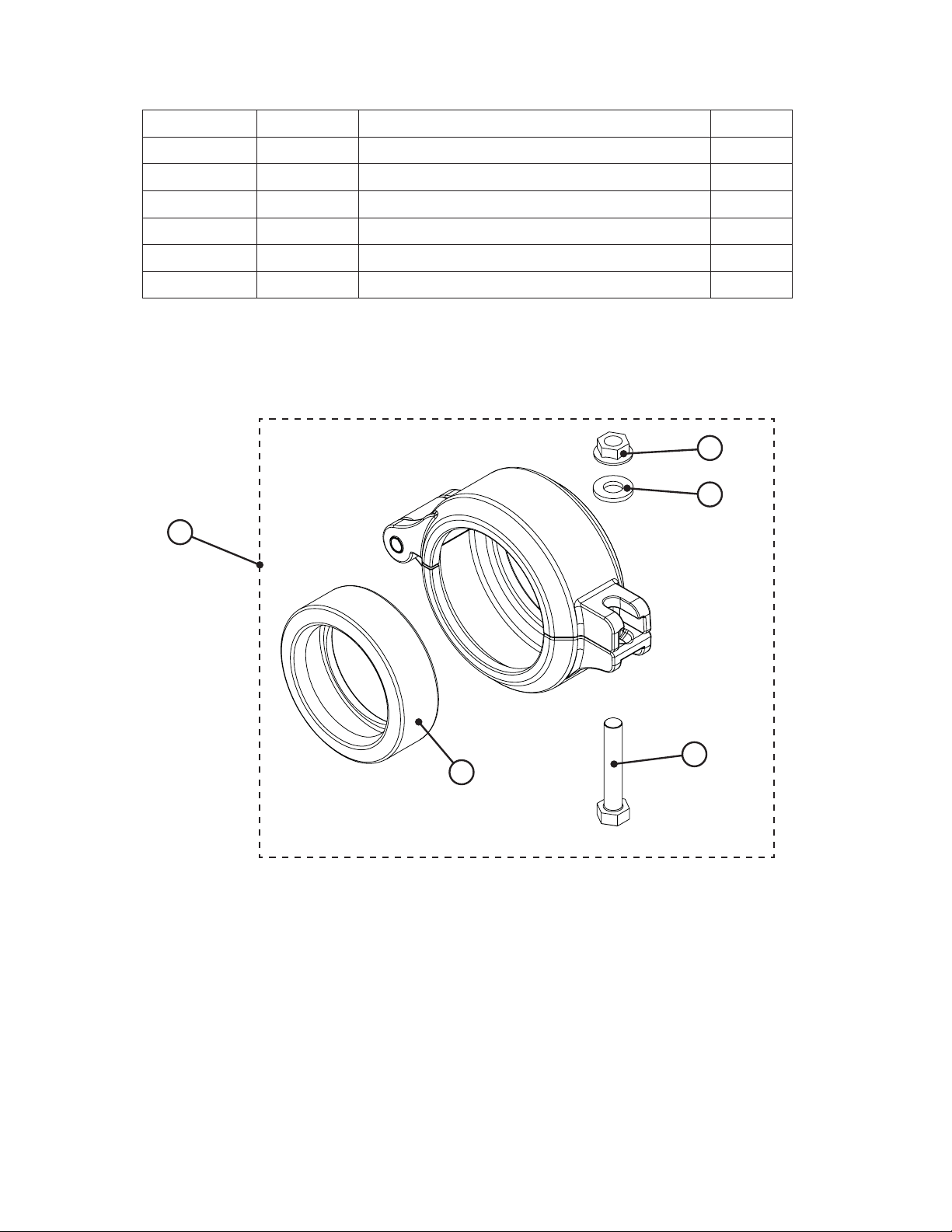
V3053 WS2 2-1/2 GROOVELOCK CLAMP ASY
Drawing No. Order No. Description Quantity
1 V3053 WS2 2-1/2 GROOVELOCK CLAMP ASY 1
2 V3290 WS2 GROOVE LOCK SEAL 2.5 1
3 V3269 WS2 NUT 5/16-18 SS HEX 1
4 V3293 WS2 WASHER SS 5/16 FLAT 1
5 V3276 WS2 BOLT HEX SS 5/16-18X1-3/4 1
Not Shown S3086 SILICONE LUBRICANT 1
3
4
1
5
2

WS2H Control Valve Manual Page 33
Erro r Codes
Error Descriptio n Possible Cause
Drive m otor is notengaged with mating gear
1001
1003 Run time to long
Encoderon m ain board is
not r egisteringpulses
Unexpected s tall1002
Faultydrivemotor or wiring
Reflectors on reductiongear are dirtyor d amaged
Circuitboard is not properlyengaged with drive bracket
Faultyencoder /ma in board
Debris jam ming pis ton
Faultydrive m o tor
Faultydr ive component creating drag
Main drive gear not properlyengaged
Motorpinion s l ipping on s haft
Faulty motor or wiring
15003
15010
15011
17000
17002
# Units
Bypass motor runtime to
long
Bypassruntimetoshort
while tr ying to driv eoffline
Bypassruntimetoshort
while trying to drive online
Separate source inletdrive
runtim e to long
Separate source inletdrive
error
Master has los t
comm unication with another
unit
Mis sing engagem ent between bypass drive mo torand main gear
Bypass drive motornotconnected tom ain board
Faultybypass drive m otor or wiring
Debris jam ming drive
Faultydr ive component creating drag
Debris jam ming drive
Faultydr ive component creating drag
Mis sing engagem ent between separates ource drive m otorand main gear
Separate source drive m otor not connected to s ystem board
Faultyseparate s ource drive m o toror wiring
Debris in separ ate s ource valve
Faultydr ive component creating drag
Faultycom munication cable
Other unit has los t power or is in error m ode
More than one unit is programmed as master

Page 34 WS2H Control Valve Manual
Order No. V3010-2A
4
3
2
Flow Rate (gpm)
1
0
20 40 60 80 100 120
US Units
Total
Slow Rinse
Draw
Pressure (psi)
Order No. V3010-2C
US Units
7
6
5
4
3
Flow Rate (gpm)
2
1
0
20 40 60 80 100 120
Total
Slow Rinse
Draw
Pressure (psi)
Order No. V3010-2B
6
5
4
3
2
Flow Rate (gpm)
1
0
20 40 60 80 100 120
US Units
Total
Slow Rinse
Draw
Pressure (psi)
Order No. V3010-2D
US Units
12
10
8
6
4
Flow Rate (gpm)
2
0
20 40 60 80 100 120
Total
Slow Rinse
Draw
Pressure (psi)
Order No. V3010-2E
16
14
12
10
8
6
Flow Rate (gpm)
4
2
0
20 40 60 80 100 120
US Units
Total
Slow Rinse
Draw
Pressure (psi)
Order No. V3010-2G
US Units
24
22
20
18
16
14
12
10
8
Flow Rate (gpm)
6
4
2
0
20 40 60 80 100 120
Total
Slow Rinse
Draw
Pressure (psi)
Order No. V3010-2F
US Units
18
16
14
12
10
8
6
Flow Rate (gpm)
4
2
0
20 40 60 80 100 120
Total
Slow Rinse
Draw
Pressure (psi)

WS2H Control Valve Manual Page 35
Order No. V3010-2A
Metric Units
16
14
12
10
8
6
Flow Rate (lpm)
4
2
0
100 200 300 400 500 600 700 800 900
Total
Slow Rinse
Draw
Pressure (kPa)
Order No. V3010-2C
27
24
21
18
15
12
9
Flow Rate (lpm)
6
3
0
100 200 300 400 500 600 700 800 900
Metric Units
Total
Slow Rinse
Draw
Pressure (kPa)
Order No. V3010-2E
Metric Units
60
Order No. V3010-2B
21
18
15
12
9
Flow Rate (lpm)
6
3
0
100 200 300 400 500 600 700 800 900
Metric Units
Total
Slow Rinse
Draw
Pressure (kPa)
Order No. V3010-2D
Metric Units
40
35
30
25
20
15
Flow Rate (lpm)
10
5
0
100 200 300 400 500 600 700 800 900
Total
Slow Rinse
Draw
Pressure (kPa)
Order No. V3010-2F
Metric Units
70
50
40
30
20
Flow Rate (lpm)
10
0
100 200 300 400 500 600 700 800 900
Total
Slow Rinse
Draw
Pressure (kPa)
Order No. V3010-2G
Metric Units
90
80
70
60
50
40
30
Flow Rate (lpm)
20
10
0
100 200 300 400 500 600 700 800 900
Total
Slow Rinse
Draw
Pressure (kPa)
60
50
40
30
Flow Rate (lpm)
20
10
0
100 200 300 400 500 600 700 800 900
Total
Slow Rinse
Draw
Pressure (kPa)

Page 36 WS2H Control Valve Manual
Revision History:
06/21/07
PAGE 3:
2) Maximum power through relays
a. 1A, 30 VDC
b. 1A, 30 VAC
PAGE 29:
V3260BSPT-02 WS2 SIDE MOUNT BASE BSPT ASY
Added drawing and table
PAGE 31:
6 V3264 WS2 BYPASS REDUCTION GEAR AXLE 3 N/A
06/25/07
PAGE 29:
V3260-02 WS2 SIDE MOUNT BASE NPT
09/06/07
PAGE 27:
Update Tubine Asy. part# V3118-03 and Turbine Asy. drawing
Form No. V3215 – 9/06/07
U.S. Patents: 6,402,944; 6,444,127; and 6,776,901
 Loading...