

Clack CF1044-3B, CF1248-3B, CF1354-3B, CF1465-3B, WS1TC Series Installation, Operation & Maintenance Manual

FILOX Series Filter
Installation Operation Maintenance Manual
Installation
Operation
Maintenance
Manual
FILOX Filter
WS1TC Series Valve
Models
CF1044-3B CF1248-3B CF1354-3B
CF1465-3B
FILOXWS1-3B APRIL 2011 \page 1

FILOX Series Filter
Installation Operation Maintenance Manual
1.0 UNPACKING AND PARTS LIST........................................................................................................4
1.1 UNPACKING NOTES ......................................................................................................................4
1.2 BASIC PARTS LIST.........................................................................................................................4
1.3 MISSING OR DAMAGED GOODS.................................................................................................4
2.0 TEMPORARY STORAGE.................................................................................................................... 4
3.0 GENERAL NOTES....................................................................................................................... 5
3.1 FILOX-R Media ............................................................................................................................5
3.2 System Management...................................................................................................................... 5
4.0 REGENERATION/BACKWASH.........................................................................................................6
4.1 The Backwash Process....................................................................................................................... 6
4.2 TIME CLOCK CONTROL OF REGENERATION INITIATION ................................................... 6
5.0 PRE-INSTALLATION CHECKS................................................................................................. 7
5.1 MECHANICAL............................................................................................................................. 7
5.1.1 Foundation/Drainage............................................................................................................ 7
5.1.2 Operating Space ................................................................................................................... 7
5.1.3 Incoming Water.................................................................................................................... 7
5.1.4 Pipework .....................................................................................................................................8
5.1.5 Water Supply Company Requirements ....................................................................................... 8
5.2 ELECTRICAL ...................................................................................................................................8
6.0 ASSEMBLY/INSTALLATION............................................................................................................ 9
6.1 MECHANICAL................................................................................................................................. 9
6.1.1 Pipework .....................................................................................................................................9
6.1.2 Drains and overflow connections................................................................................................ 9
6.2 ASSEMBLY ....................................................................................................................................10
7.0 COMMISSIONING..................................................................................................................... 12
7.1 INTRODUCTION.......................................................................................................................12
7.2 Setting the Time of Day ...................................................................................................................12
7.3 Regeneration Programming ............................................................................................................. 13
7.4 User Programming...........................................................................................................................14
7.3 COMMISSIONING..................................................................................................................... 15
8.0 ROUTINE MONITORING ................................................................................................................. 16
9.0 FAULT FINDING AND RECTIFICATION....................................................................................... 17
9.1 NO FLOW TO SERVICE................................................................................................................17
9.2 POOR TREATED WATER QUALITY .......................................................................................... 17
9.3 NO BACKWASH............................................................................................................................ 18
9.4 UNSATISFACTORY CAPACITY BETWEEN BACKWASHES................................................. 18
10.0 WARRANTY AND SERVICE ......................................................................................................... 19
11.0 TECHNICAL DATA......................................................................................................................... 20
11.1 PROCESS AND OPERATING DATA ......................................................................................... 20
11.2 ENGINEERING DATA................................................................................................................. 21
12.0 SPARES LIST.................................................................................................................................... 22
13.0 DECLARATION OF CONFORMITY..............................................................................................23
FILOXWS1-3B APRIL 2011 \page 2

FILOX Series Filter
Installation Operation Maintenance Manual
1.0 UNPACKING AND PARTS LIST
1.1 UNPACKING NOTES
The unpacking of the Filter is quite straightforward, and there are no ‘hidden’
items. It is advisable to keep the packages sealed until such time as they are
used, to prevent dust or water entry.
1.2 BASIC PARTS LIST
1. VALVE (c/w flow controllers on outlet and drain)
2. Clack MANUAL
3. INSTRUCTIONS
4. VESSEL (c/w riser and distribution system)
5. 4” - 2 1/2” REDUCER (if required)
6. FILOX MEDIA (qty as specified)
1.3 MISSING OR DAMAGED GOODS
Immediately on receipt of the goods, it is advisable to check that all items
ordered have been received. If you have any doubt that goods have been
supplied as requested, please contact your supplier immediately. If any items
are missing or damaged, the carrier and your supplier must be notified within 2
days of receipt if a claim is to be made.
2.0 TEMPORARY STORAGE
If installation is not to start immediately after delivery, the equipment should be
stored in a clean dry area, where it will not be damaged, or be subjected to
temperatures below freezing.
FILOXWS1-3B APRIL 2011 \page 3

FILOX Series Filter
Installation Operation Maintenance Manual
3.0 GENERAL NOTES
These instructions cover the FILOX Range of filters, which includes model numbers
from CpH 1054 to CpH3072.
It is recommended that these instructions are read thoroughly before commencing any
work on the unit, particularly if you have no previous experience of installing and using
a filter.
3.1 FILOX-R Media
FILOX is a synthetic Mangenese Dioxide filter medium for the removal of
iron and manganese from water.
FILOX filter media requires backwashing with the raw water to clear the bed. The
operating parameters for FILOX make it suitable for a number of water types.
3.2 System Management
In order to remove accumulated deposits from the filter bed, the water flow through
the filter is reversed (backwashed). Water is run to drain at a high rate to separate
the filter media from the deposits. The control valve completes the backwash cycle
automatically at the intervals and times set during installation. Backwash and fast rinse
times are set for 20 minutes per cycle but can be altered to suit individual
requirements.
Due to the density of FILOX media a high backwash flow is required to ensure a good
lift of the bed and to allow all accumulated debris to be removed. All filter valves
have the option of an additional volt free microswitch, which can be used to
initiate a regen pump etc.
FILOXWS1-3B APRIL 2011 \page 4

FILOX Series Filter
Installation Operation Maintenance Manual
4.0 REGENERATION/BACKWASH
4.1 The Backwash Process
The backwash process consists of two stages:-
Backwash - Water flows upwards through the media bed, and out to a drain. As
it does so it separates the deposits from the filter media and cleans off any
particles of dirt or pipework corrosion products, which may have accumulated
during the service cycle.
Fast Rinse - This follows the backwash cycle and entails rinsing away any
residual deposits from the media and re-packing the media bed. This is
carried out down flow with water flowing through the media in the direction of
service.
4.2 TIME CLOCK CONTROL OF REGENERATION INITIATION
Most filter application systems are supplied with a time clock configuration
valve, which initiate regeneration at a pre-set time (usually 2:00 AM) after a
pre-set number of days. The frequency of regenerations is fully adjustable,
but a minimum of once every 3 days is recommended.
FILOXWS1-3B APRIL 2011 \page 5

FILOX Series Filter
Installation Operation Maintenance Manual
5.0 PRE-INSTALLATION CHECKS
5.1 MECHANICAL
5.1.1 Foundation/Drainage
The filter will not require any special foundations, provided that a firm, level
area, which is capable of supporting the working weight, is available. (See
Engineering Data, Section 11.2)
Unwanted water from the backwash process must flow to drain, and so an
open drain or gully, capable of passing the necessary flow is required (see
Process and Operating Data, 11.1, for relevant flows). The total flow of
water to drain depends on site conditions, but will be at least the same as
the service flow. Preferably the drain should be level but no higher than
500mm above the filter valve.
5.1.2 Operating Space
The space occupied by the filter can be found in the Engineering Data (Section
11 .2).
Access will be required to carry out adjustments or maintenance on the
equipment. It is therefore recommended that a minimum of 500mm clearance
be allowed around the unit for this purpose.
5.1.3 Incoming Water
The raw water to be fed to the filter must comply with the following:-
1. Temperature = 3 -45C (35- 110F)
2. No Oil or Polyphosphates
3. Backwash flow rate must be twice the service flow rate available with a
pressure of 2 bar
FILOXWS1-3B APRIL 2011 \page 6

FILOX Series Filter
Installation Operation Maintenance Manual
5.1.4 Pipework
Pipework to be connected to the filter should not have an excessive amount of
deposits. Piping that is heavily built up with scale (or Iron deposits) should be
replaced.
Make sure that the pipework can be connected to the filter in such a way as to
impose no stresses on the control valve, and that it is properly aligned and
supported.
A system for the complete by-passing and isolation of the filter should be
installed.
5.1.5 Water Supply Company Requirements
During backwash the accumulated debris and oxidised iron and manganese is
flushed to drain. Please contact your local Water Authority for advice on
effluent issues if concerned with flow to drain.
5.2 ELECTRICAL
All filter valves are supplied as 12v complete with a transformer for 240v. A
continuous supply of 240v, 5 VA is required which should be provided by an
uninterrupted mains supply, which is separately 1 Amp fused, and does not
have any additional switch.
A plug is provided with this filter, the cable should be connected to fused
spur outlet. However if that is not possible then a plug should be fitted to the
cable with a 1 amp fuse. The socket used should be unswitched to prevent the
filter from being inadvertently turned off.
FILOXWS1-3B APRIL 2011 \page 7

FILOX Series Filter
Installation Operation Maintenance Manual
6.0 ASSEMBLY/INSTALLATION
6.1 MECHANICAL
Check all the items against the parts list and shipping documents, and ensure
you have them all before starting work. In addition to the filter you will require
installation materials and basic tools, (i.e., spanners, screwdrivers etc., and
PTFE tape)
6.1.1 Pipework
Pipework can be constructed from any normally acceptable material (Copper,
Galvanised, Plastic), provided it is properly supported and aligned. Ensure that
the pipe is sufficiently large to accommodate the flow of water required,
making due allowance for the pressure drop between the filter and the point of
discharge of treated water.
NOTE: IF BRAZED OR SOLDERED FITTINGS ARE TO BE USED, THE
PIPE WORK MUST BE DISCONNECTED FROM THE VALVE DURING
HEATING AND COOLING. EXCESS HEAT CAN CAUSE PERMANENT
DAMAGE TO SOME OF THE VALVE COMPONENTS.
6.1.2 Drains and overflow connections
The drain connection from the backwash valves is a 3/4" or 1” BSPM thread.
Flexible tube should be run from this spigot to a drain capable of taking the
maximum flow in regeneration (see Section 11.2), and leaving a similar gap
above the drain edge. The drain must not be higher than 500mm above the
control valve and preferably should have an air break at the same height as the
control valve.
FILOXWS1-3B APRIL 2011 \page 8

FILOX Series Filter
Installation Operation Maintenance Manual
6.2 ASSEMBLY
Refer to the installation diagrams in Section 13 and note the
direction of flow through the system.
Ensure the installation site is clear and level.
Ensure that the piping system in the building transfers the treated water
into a vented header tank to feed any hot water systems.
If possible, place the filter vessel into its final location before filling. Check
that the riser tube has the cap in place before commencing filling.
Using a hose 1/3 fill the vessel with water. This is to prevent damage to the
bottom distributor when pouring in the media.
Using a funnel slowly pour in the support gravel. Next, slowly pour in the
FILOX media, taking care not to spill any on the floor and that the riser
remains central in the vessel during filling.
After pouring in all of the filter media, the vessel should be, at most, 50% full.
This is to allow rising space for the media during the backwashing cycle. Once
the vessel is filled, immediately sweep up any spilled filter media.
Remove the cap from the riser tube and brush any debris out of the threads
in the neck of the filter vessel.
Unpack the valve and reducer (if used). Screw the reducer into the filter
vessel, then slip the valve down onto the distributor tube. No top distributor is
used on filter valves to allow the maximum amount of debris to be
backwashed off the media.
Screw the valve into the filter vessel, taking extreme care not to cross the
threads. As the valve is being run into the vessel excessive force should not be
required. Finally tighten to approximately 20ft.lbs torque.
Adjust the position of the filter vessel to line up with the pipework
connections, not the position of the valve on the vessel.
Connect the inlet and outlet pipework to the valve using flexible connections
or plastic high pressure piping. Flexible pipework is essential to prevent
stress on the vessel as it cycles during service since it will expand and
contract longitudinally.
FILOXWS1-3B APRIL 2011 \page 9

FILOX Series Filter
Installation Operation Maintenance Manual
Connect the drain line to the outlet of the drain line flow controller on
the valve.
Ensure that there is an airbreak in the drain at the same height as the
valve to prevent negative pressure on the vessel.
Connect the power supply to the valve and the unit is now ready for
commissioning.
FILOXWS1-3B APRIL 2011 \page 10

FILOX Series Filter
Installation Operation Maintenance Manual
7.0 COMMISSIONING
7.1 INTRODUCTION
It is recommended that the commissioning of the plant is undertaken by a trained
service engineer, who will be able to put the plant into service quickly, and most
efficiently. However, if the services of an experienced engineer are not available,
following the steps outlined below will result in thesystem being properly commissioned.
7.2 Setting the Time of Day
Press Set Hour
set the clock to the Closest Hour by Using the Up and
Down buttons. An arrow points to PM after 12. after Power failure the time of day
will need to be reset. Press SET HOUR to exit
The filter regeneration cycles have been factory programed.
The time of day for regeneration to take place has been entered as 2.00 AM and
this can be altered depending on site requirements.
FILOXWS1-3B APRIL 2011 \page 11

FILOX Series Filter
Installation Operation Maintenance Manual
7.3 Regeneration Programming
(All programming below is Factory set)
To enter Installer level press SET Hour +Up for 3
seconds and then SET HOUR + UP for 3 seconds
Set to P.8 then press SET HOUR
Leave set to – press SET HOUR
press SET HOUR. Set to 50 press SET HOUR
FILOXWS1-3B APRIL 2011 \page 12
Set to 99,
FILOX Series Filter
Installation Operation Maintenance Manual
then press SET HOUR to exit Installer Level.
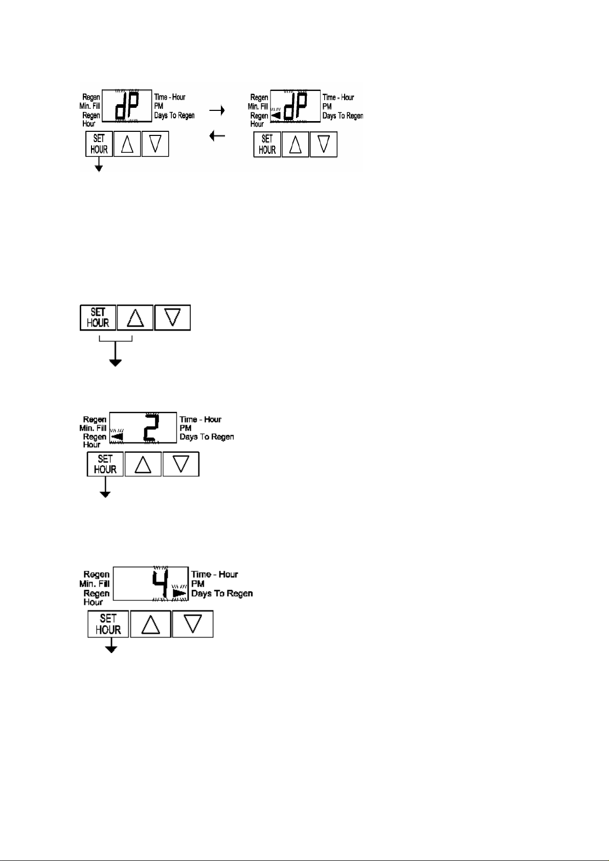
7.4 User Programming
(All programming below is Factory set)
Set to dP and arrow
To enter User level press SET HOUR + UP for 3
seconds
Set the Clock to the hour of regeneration
using the up and down buttons, after 12 an arrow appears against PM,
press SET HOUR
Set the number of days between
regenerations, the allowable range is 1 to 99, press SET HOUR to exit
User Programming.
FILOXWS1-3B APRIL 2011 \page 13

FILOX Series Filter
Installation Operation Maintenance Manual
7.3 COMMISSIONING
7.3.1 The objective of commissioning is to fill the filter with water, check for leaks
and prepare it for service. The simplest way to commission the unit is to
initiate a backwash. This will eliminate the air from the system and flush the
media prior to use.
7.3.2 Before opening the inlet water supply switch on the power, which will activate
the piston motor and the timer motor.
7.2.3 Next, start a manual backwash by pressing the UP and DOWN button
together for 3 sec or until the motor starts to turn.
7.2.4 When the motor has stopped switch off the power and slowly open the
inlet water supply. At first, air will be expelled from the drain line, followed by
water once the vessel is full. Allow water to run to drain on the backwash
cycle until the drain line runs clear in order to rinse the filter media and
remove any fines.
7.2.5 Turn the power back on and allow the complete a manual regen in full by
pressing the down button and allowing the valve to complete the cycle.
7.2.9 The filter is nowcommissioned.
FILOXWS1-3B APRIL 2011 \page 14

FILOX Series Filter
Installation Operation Maintenance Manual
8.0 ROUTINE MONITORING
The following recommendations are made to help the user of the filter
confirm that it is performing as required, and to give early warning of
possible problems. The operation of the filter is completely automatic,
and should not require adjustment.
Weekly
Checkthe treated water qualitywithatest kit.
Monthly
Check rawwaterquality, and record.Compare with original qualityand
adjust frequency of backwash if required.
Six Monthly
Perform a chlorinated backwash to remove any organic build up on the
media. Check filter media depth against original level.
Annually
Inspect and clean/replace as necessary the piston and the internal
seals. A competent engineer familiar with Clack valves should perform
this.
FILOXWS1-3B APRIL 2011 \page 15

FILOX Series Filter
Installation Operation Maintenance Manual
9.0 FAULT FINDING AND RECTIFICATION
9.1 NO FLOW TO SERVICE
Check mains pressure is above 1.7 bar.
Check inlet water supply
Check inlet and outlet isolating valves are open.
Check service outlet valve is open.
Check pressure drop across media. If excessive, media may be fouled,
or internals blocked. Initiate a backwash. If this does not free up the media
the filter will need to be inspected and serviced by a competent engineer.
Backwash with chlorine solution to remove organic build up
9.2 POOR TREATED WATER QUALITY
Check manual by-pass closed.
Check raw water pressure above minimum. If flow is less than design rate,
channelling of water can occur in media, which results in inadequate
treatment.
Backwash with chlorine solution to remove organic build up
Increase frequency of backwash as media may be becoming
overloaded.
Increase backwash flow.
Check piston and seals & spacers. Check raw
water analysis for changes
FILOXWS1-3B APRIL 2011 \page 16

FILOX Series Filter
Installation Operation Maintenance Manual
9.3 NO BACKWASH
Check electrical supply, fuses etc. satisfactory.
Check program.
Check timer motor is running.
Check drive motor runs, by manually initiating a backwash, and listening
for drive motor as it advances between cycles. Replace if necessary.
9.4 UNSATISFACTORY CAPACITY BETWEEN BACKWASHES
Increase frequency of backwash
Check age of media and media level
Backwash with chlorine solution to remove organic build up
Increase backwash flow
FILOXWS1-3B APRIL 2011 \page 17

FILOX Series Filter
Installation Operation Maintenance Manual
10.0 WARRANTY AND SERVICE
Your filter is covered by a parts warranty for a period of one year from
installation or 14 months from purchase.
Consumable filter media is excluded from this warranty
Should you have any problems with your filter or require a routine
service, please contact your supplier.
FILOXWS1-3B APRIL 2011 \page 18

FILOX Series Filter
Installation Operation Maintenance Manual
11.0 TECHNICAL DATA
11.1 PROCESS AND OPERATING DATA
PARAMETER UNITS CF1044-3B CF1248-3B CF1354-3B CF1465-
3B
FLOW RATE M3/HR 0.9 1.35 1.8 2.3
BACKWASH
FLOW
REGEN
TIMES
MAX TEMP C 45
M3/HR 1.8 2.6 3 3.5
MIN 16
FILOXWS1-3B APRIL 2011 \page 19

11.2 ENGINEERING DATA
FILOX Series Filters
FILOX Series Filter
Installation Operation Maintenance Manual
MODEL CF1044-
3B
VALVE
FILTER
VESSEL
HEIGHT
(MM)
DIAMETER
OF VESSEL
(MM)
VALVE
INLET
VALVE
OUTLET
VALVE
DRAIN
QTY
GRAVEL
QTY FILOX 2 3 4 5
POWER 240 VAC 1.2 VA
1054 1248 1354 1465
1607 1458 1601 1984
254 305 331 356
0.25 0.5 0.75 1.5
CF1248-3BCF1354-
3B
1”
1”
¾”
CF1465-
3B
PRESSURE 1.7 Bar MAXIMUM OPERATING TEMPERATURE
45.0C HEADROOM - Allow 100 mm greater than overall height.
FILOXWS1-3B APRIL 2011 \page 20

FILOX Series Filter
Installation Operation Maintenance Manual
12.0 SPARES LIST
PART NO. DESCRIPTION
XCV3011 Piston WS1TC
XFR1 Riser Tube c/w 1” Dist
XCV3005 Seal & Spacer kit WS1TC
XCV3107-01 Drive Motor 12v
VDLFC3 3/4” Brass flow controller (please specify)
VDLFC4 1” Brass flow controller (please specify)
FILOXWS1-3B APRIL 2011 \page 21

FILOX Series Filter
Installation Operation Maintenance Manual
13.0 DECLARATION OF CONFORMITY
EURAQUA UK
FILOX FILTER USING CLACK WS1TC VALVE
Conform to the following EC Directives where required:
Rob Adam
The Electromagnetic Compatibility Directive 89/336/EEC
(including any additions or amendments thereafter)
and
The Low voltage Directive (Electrical Safety) 73/23/EEC
(including any additions or amendments thereafter)
and
The Machinery Directive 89/392/EEC
(including any additions or amendments thereafter)
Technical Director
FILOXWS1-3B APRIL 2011 \page 22
 Loading...