

MANUALE D’USO
MODULO 9V
evolution
90821
I
002
UK
023
F
000
D
000
E
000
P
000
GR
000
PL
000
Modulo di comando evolution
MODULO DI COMANDO EVOLUTION
Ringraziando per la fi ducia concessa con l’acquisto di questo prodotto,
consigliamo di leggere attentamente questo manuale di istruzioni prima
di iniziare la programmazione. Ogni paragrafo vi darà tutte le indicazioni
su come eseguire correttamente ogni singola operazione.
Dichiarazione di conformità
Claber S.P.A.
Via Pontebbana 22 – 33080 – Fiume Veneto – Pordenone Italy
Assumendone la piena responsabilità dichiariamo che il prodotto:
90821 – Modulo di comando
È conforme alla direttiva europea 2004/108/CE con riferimento alle norme
tecniche EN61000-6-1:2007 (immunità) e EN61000-6-3:2007 (emissione).
Fiume Veneto, 11/01/2010 Il Responsabile
2010
Dott. Marzona Federico
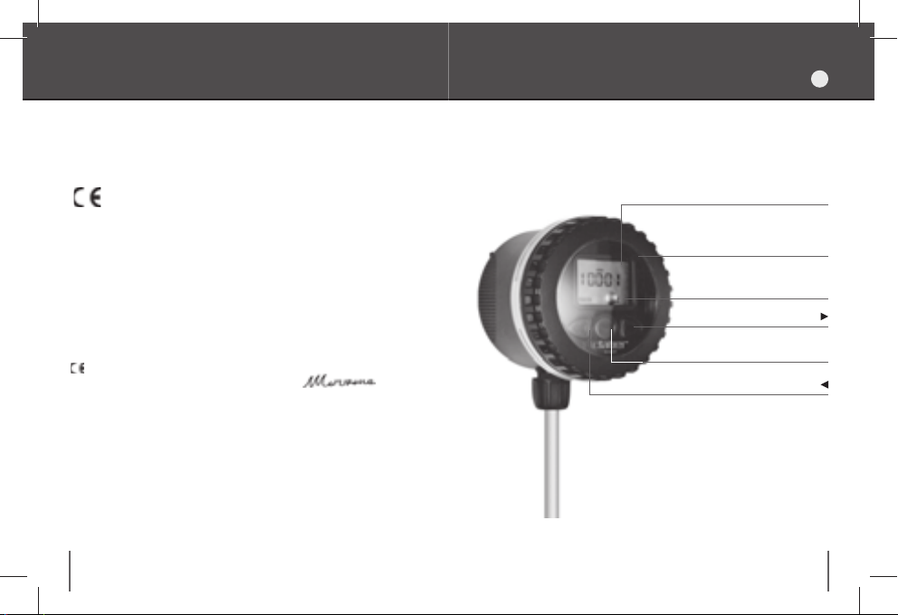
COPERCHIO TRASPARENTE
GRUPPO DI COMANDO
DISPLAY
TASTO AVANTI
TASTO ENTER
TASTO INDIETRO
Raccomandazioni
1.
Utilizzare esclusivamente batterie alcaline da 9V nuove.
2.
Sostituire la batteria all’inizio di ogni stagione.
3.
Controllare periodicamente l’integrità delle guarnizioni di tenuta del
coperchio e del tappo dell’alloggiamento della batteria.
4.
Controllare periodicamente che i collegamenti elettrici della batteria e
del solenoide siano ben fi ssati.
5.
Chiudere sempre il coperchio per garantire la tenuta stagna del prodotto.
2 3
I

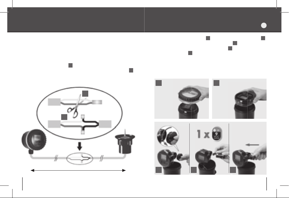
Installazione
INSTALLAZIONE
I
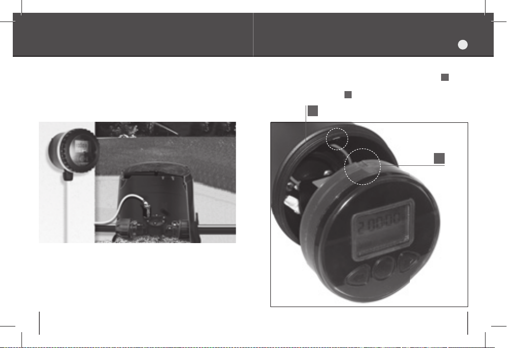
Il modulo di comando è a perfetta tenuta stagna e funziona anche immerso permanentemente in acqua fi no a un metro di profondità (grado
di protezione IP68). Può essere installato all’aperto o all’interno
di pozzetti.
4 5
Attenzione:
per ottenere l’ermeticità del prodotto è necessario assicurarsi che il gruppo di comando sia allineato ed inserito nella apposita
guida 1 e che il coperchio trasparente sia perfettamente avvitato, con
la guarnizione di tenuta ben posizionata nella sede 2.
2
1

Installazione
INSTALLAZIONE
I
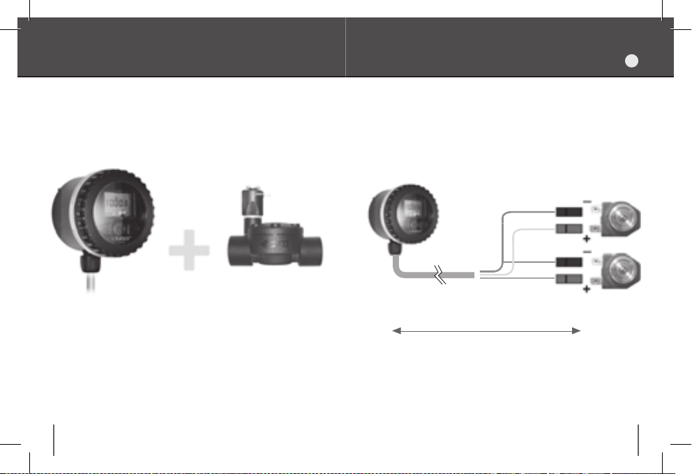
Il modulo di comando può pilotare fi no a due elettrovalvole con solenoide
bistabile a 9V.
1.
Collegare il fi lo
2.
Collegare il fi lo
3.
Collegare il fi lo
verde
al polo (- ) di ciascuna elettrovalvola (comune).
bianco
marrone
al polo (+) dell’
al polo (+) dell’
elettrovalvola A
elettrovalvola B
.
.
Elettrovalvola A
verde - comune
bianco - linea A
marrone - linea B
Elettrovalvole
bistabili 9-12V
- Ø 1” F
90822
90823
- Ø 1” M
90881
- Ø 1/2” M
6 7
75 cm inclusi
max 30 m (sezione 1,5 mm
Elettrovalvola B
2
)
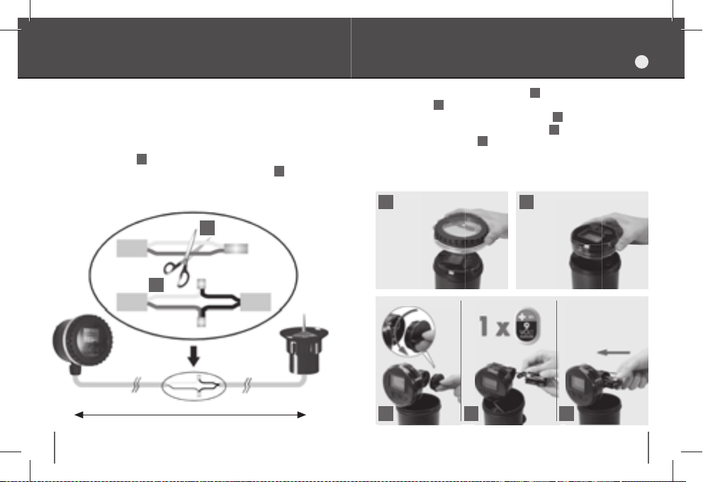
Collegamento ad un Rain Sensor
Inserimento della batteria
I
1.
È possibile collegare al modulo di comando un sensore di pioggia (Rain
Sensor Claber cod. 90915). Il sensore di pioggia interrompe i programmi
di irrigazione in caso di pioggia, ripristinandoli automaticamente quando
l’acqua raccolta al suo interno è evaporata.
1.
Interrompere il collegamento tra i fi li giallo e grigio, tagliando il
giunto alla loro estremità 1.
2.
Collegare i fi li giallo e grigio ai fi li provenienti dal sensore di pioggia 2.
Attenzione:
se il sensore di pioggia non viene utilizzato, occorre
assicurarsi che i fi li giallo e grigio siano collegati tra loro, ripristinando
se necessario il giunto.
1
giallo
grigio
2
Rain Sensor
90915
75 cm inclusi
8 9
max 30 m
Svitare il coperchio trasparente
2.
Svitare il tappo dell’alloggiamento della batteria 3.
3.
Connettere la batteria rispettando la polarità
nell’alloggiamento 5.
4.
Riavvitare il tappo controllando che la guarnizione di tenuta sia
correttamente posizionata in sede.
Attenzione:
1
3 4 5
utilizzare esclusivamente batterie alcaline da 9V.
1
ed es trarr e il gru ppo d i comand o
4
e reinserire la batteria
2
2
.

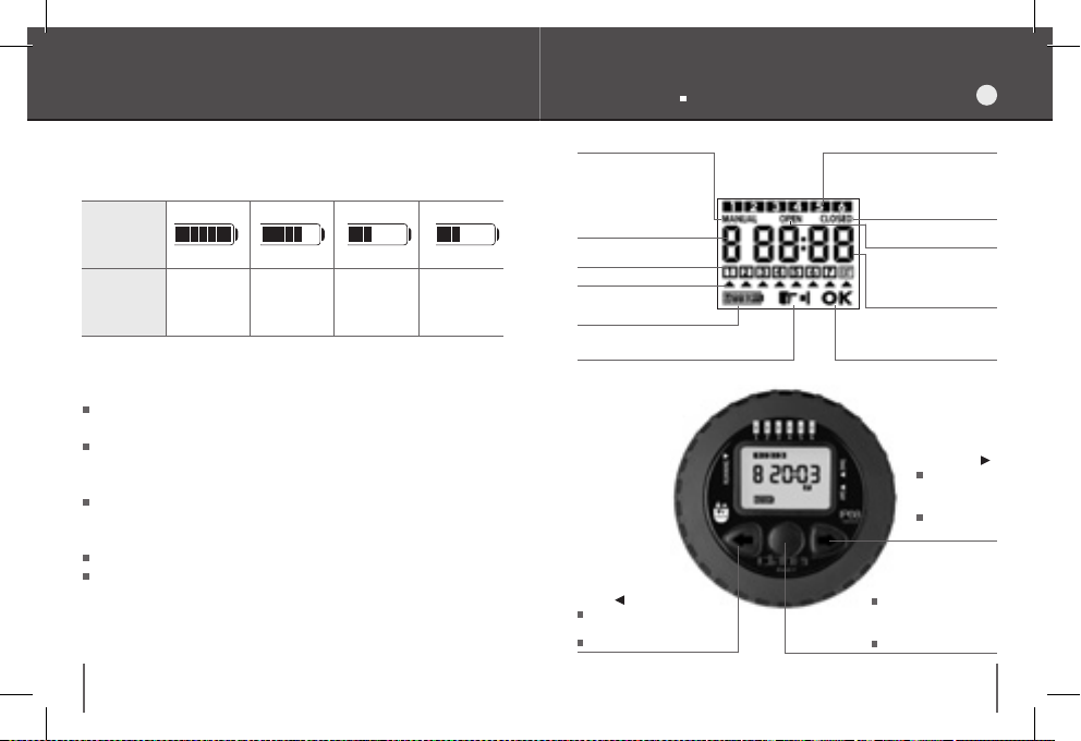
Stato di carica della batteria Display Tastiera
I
Il display visualizza lo stato di carica della batteria:
Indicatore
di carica
della
batteria
Stato
di carica
BA T T E RY BA T T E BA T BA T
(LAMPEGGIANTE)
Batteria
completamente
carica
Batteria
parzialmente
carica
Batteria
scarica da
sostituire
Batteria
esaurita da
sostituire
Note:
Una batteria alcalina consente di irrigare per un’intera stagione con
una media di 6 irrigazioni giornaliere.
Quando la batteria è esaurita le valvole si chiudono, le funzioni del
Funzionamento manuale
Indicatore del nr. di
programma giornaliero
selezionato
(in programmazione)
e della linea selezionata
A o B (in manuale)
Giorni della settimana
Cursore
Indicatore di carica
della batteria
Richiesta di un comando
(premere un tasto)
Tastiera
programmatore si interrompono automaticamente e l’indicatore di
carica della batteria inizia a lampeggiare.
Per evitare la perdita di dati, le operazioni di sostituzione della batteria
devono essere eseguite in un tempo inferiore a 30 secondi. Dopo la
sostituzione della batteria controllare ed eventualmente reimpostare
l’ora corrente.
Si consiglia di togliere la batteria durante i periodi di inutilizzo del
programmatore.
Per lo smaltimento delle batterie esaurite utilizzare gli appositi
contenitori di raccolta.
10 11
Indietro
Scorre indietro le pagine
Modifi ca le impostazioni
Programmi Giornalieri ( da 1 a 6)
Indicatore
di valvola chiusa
Indicatore
di valvola aperta
Indicatore numerico
dell’orologio e degli orari
di apertura e
chiusura della valvola
Modalità di modifi ca delle
Enter
Entra nelle pagine per
modifi care le impostazioni
Conferma le modifi che
impostazioni
Avanti
Scorre avanti
le pagine
Modifi ca le
impostazioni
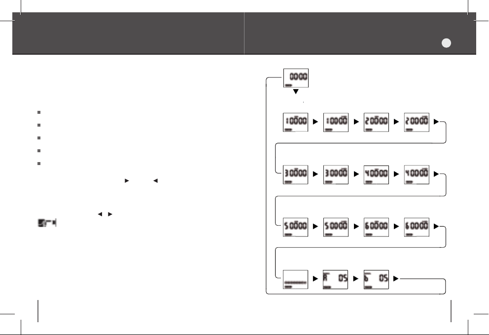
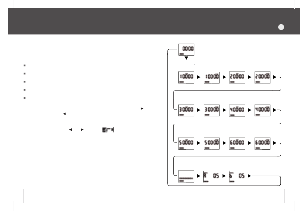
Programmazione
PROGRAMMAZIONE
I
Sono disponibili 6 programmi di irrigazione giornalieri, ciascuno dei quali
Orologio
composto da un orario di apertura e da un orario di chiusura della
valvola. La programmazione è gestita a pagine, ordinate come mostrato
in fi gura a pagina seguente:
– Programma 2 – Linea B –
a
2
apertura
a
2
chiusura
Orologio (pagina iniziale).
– Programma 1 – Linea A –
a
1
apertura
a
1
chiusura
Programmi giornalieri (da 1 a 6).
Programma settimanale.
Manuale LINEA A.
Manuale LINEA B.
– Programma 3
a
3
apert
ura
–
Linea A
a
3
chiusura
– P
rogramma 4 – Linea B –
–
a
4
ap
ertura
a
4
chi
usura
Premendo ripetutamente il tasto (oppure per procedere a ritroso) si
scorrono le varie pagine di programmazione. Una volta selezionata una
pagina di programmazione, premendo ENTER si e ntra in modali tà di mo-
difi ca delle impostazioni (il simbolo OK sul display è acceso). A questo
punto agendo sui tasti e si può modifi care l’impostazione. Il simbolo
– Programma 5 – Linea A –
a
5
ape
rtura
a
5
chiusura
– Programma 6
a
6
apertu
–
Linea B
–
a
ra
c
6
hiusura
indica la richiesta di un comando (premere un tasto). Premendo
nuovamente ENTER si conferma il cambiamento effettuato.
Programma
setti
manale
12 13
Manuale
LINEA A
Manuale
LINEA B
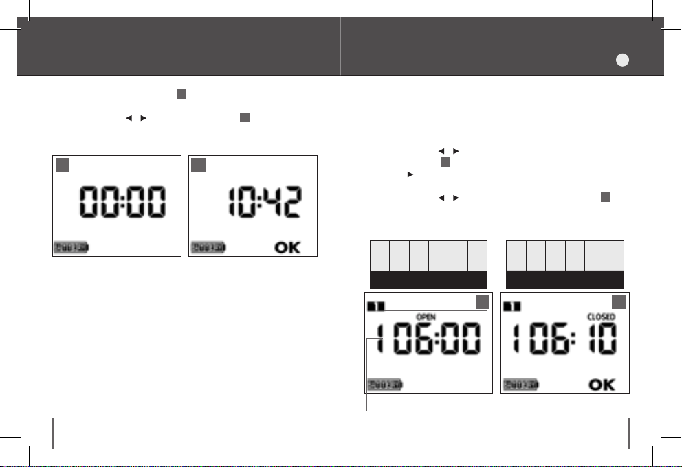
Impostazione ora corrente
Programmazione giornaliera
I
1. Selezionare la pagina orologio 1.
2. Premere ENTER.
3. Attraverso i tasti e impostare l’ora corrente 2.
4. Premere ENTER.
1 2
14 15
I programmi sono numerati da 1 a 6. I programmi 1, 3 e 5 sono riservati
alla
LINEA A
, mentre i programmi 2, 4 e 6 sono riservati alla
1.
Selezionare la pagina
2.
Premere
3.
4.
5.
6.
7.
8.
ENTER
Attraverso i tasti e impostare l’ora di apertura (OPEN).
Premere
ENTER
Premere .
Premere
ENTER
Attraverso i tasti e impostare l’ora di chiusura (CLOSED) 2.
Premere
ENTER
LINE B
LINE A
123456
.
1
.
.
.
LINE B
LINE A
PROGRAMMA 1
LINE B
LINE A
1 2
(OPEN).
LINE B
LINE A
123456
Programma impostatoProgramma selezionato
LINEA B.
LINE B
LINE A
LINE A
LINE B
Programmazione giornaliera Programmazione settimanale
Nota:
Procedere in modo analogo se si desidera impostare anche i programmi successivi.
Attenzione:
e di orario crescenti. In caso di modifi ca non sono consentite sovrapposizioni tra programmi.
Esempio:
Programma 2 (
Programma 3 (
Per impostare la seconda apertura sulla LINEA A (Programma 3), bisogna prima
inserire il Programma 2 e quindi un’apertura sulla LINEA B; il Programma 2
può anche essere inserito provvisoriamente e cancellato in un secondo tempo.
i programmi possono essere inseriti solo in ordine numerico
Programma 1 (
LINEA A
): 06:00 (OPEN), 06:10 (CLOSED)
LINEA B
): 08:00 (OPEN), 08:30 (CLOSED)
LINEA A
): 20:00 (OPEN), 20:15 (CLOSED)
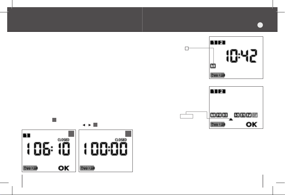
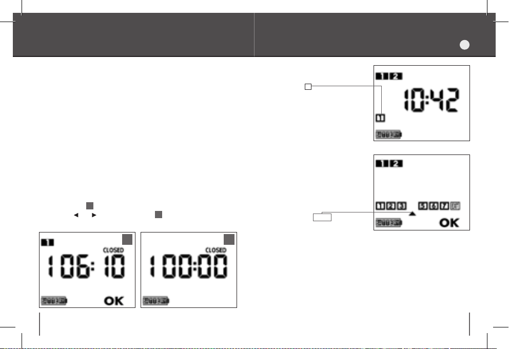
Cancellazione
dei programmi giornalieri
1.
Selezionare la pagina CLOSED del programma che si intende cancellare.
2.
Premere ENTER 1.
3.
Premere contemporaneamente i tasti e 2.
21
16 17
dopo aver impostato per la
prima volta uno o più programmi
giornalieri, il numero
viene associato al giorno corrente
della settimana, e indicato nella
pagina OROLOGIO. Se ad esempio è lunedì, si avrà che 1=lunedì,
2=martedì, 3=mercoledì, ecc.
La programmazione settimanale
consente di disattivare o riattivare
l’irrigazione in uno o più giorni della settimana.
1. Selezionare la pagina PROGRAM-
MA SETTIMANALE.
2.
Premere
3.
Posizionare il cursore in cor-
rispondenza del giorno della
settimana di cui si desidera modifi care l’impostazione.
4.
Premere
l’irrigazione nel giorno selezionato (il relativo numero sul display
scompare), oppure per riattivare
l’irrigazione.
5.
Per uscire dalla funzione po-
sizionare il cursore su
premere
ENTER
ENTER
ENTER
1
.
per disattivare
EXIT
.
e
I
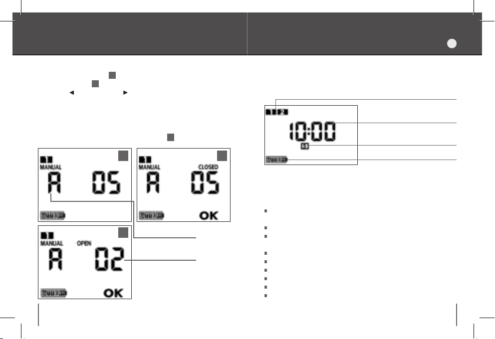
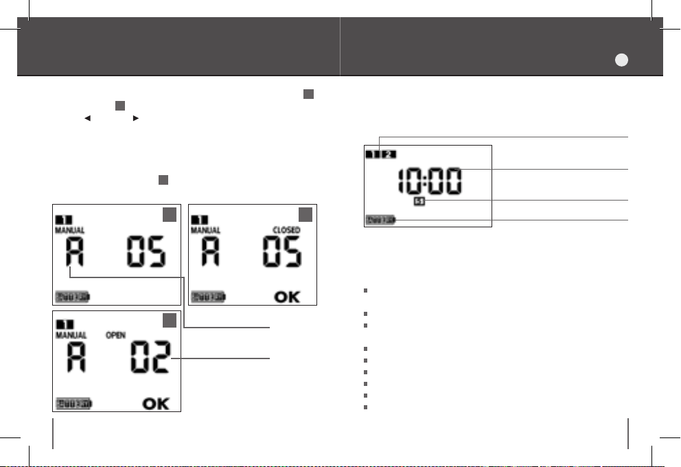
Funzionamento manuale
1.
Selezionare la pagina MANUALE della linea che si intende comandare
(LINEA A o LINEA B) 1.
2.
Premere ENTER 2.
3.
Premere per aprire oppure per chiudere la valvola.
4.
Con la valvola chiusa, premere ENTER per uscire dalla funzione
Lettura del display
Lettura del display nella pagina dell’ora corrente
Programmi impostati
(simbolo lampeggiante
se l’irrigazione è attiva)
manuale e tornare al menu principale.
Nota:
se non si interviene manualmente per interrompere l’irr igazione,
la valvola si chiude automaticamente dopo 5 minuti dall’apertura.
Il display indica il tempo di irrigazione residuo 3.
1
2
(è il quinto giorno a partire
dalla prima programmazione)
Stato di carica della batteria
Ora corrente
Giorno della set timana
Caratteristiche tecniche
Programmatore a 2 linee (A e B), utilizzabile con elettrovalvole a
solenoide bistabile a 9-12 VDC
3
18 19
Linea selezionata
Tempo di irrigazione
residuo
Possibilità di pilotare le elettrovalvole fi no a 30 m di distanza
6 Programmi giornalieri di irrigazione
(3 sulla
LINEA A
e 3 sulla
LINEA B
)
Tempi di irrigazione da 1 minuto a 23 ore 59 minuti
Programmazione settimanale
Funzione manuale
Ingresso per sensore di pioggia
Temperatura di esercizio da +5 a +70°C
Grado di protezione IP68
I

Garanzia
I
Smaltimento (RAEE)
Il simbolo in questione applicato sul prodotto o sulla confezione indica
che il prodotto non deve essere considerato come un normale rifi uto
domestico, ma deve essere portato nel punto di raccolta appropriato per
il riciclaggio di apparecchiature elettriche ed elettroniche.
Provvedendo a smaltire questo prodotto in modo appropriato si
L’apparecchio è garantito per due anni dalla data di acquisto che
sarà certifi cata dalla fattura, ricevuta o scontrino fi scale rilasciato
all’atto dell’acquisto. La garanzia decade in caso di manomissione
dell’apparecchio o per la mancanza di uno dei giustifi cativi fi scali.
Riportare il numero di matricola
contribuisce ad evitare potenziali conseguenze negative, che potrebbero
derivare da uno smaltimento inadeguato del prodotto.
Per informazioni più dettagliate sul riciclaggio di questo prodotto,
contattare l'uffi cio comunale, il servizio locale di smaltimento rifi uti o il
negoziante da cui è stato acquistato il prodotto.
Condizioni di garanzia
Claber garantisce che il prodotto è esente da difetti di materiale o di fabbricazione. Entro il
periodo di due anni dalla data di consegna al consumatore, Claber prov vederà senza addebito
alla riparazione o alla sostituzione di parti della stessa riconosciute difettose, in prodotti
impiegati in condizioni di normale esercizio e corretta manutenzione che non siano stati
manipolati o modifi c ati. Claber non ac cetta alcuna respons abilità per danni deriv ati da uso non
corret to ed improprio o da errori di installazione ed uso del prodotto, né per prodot ti non dalla
stessa fabbricati, anche se us ati in combinazione con i propri. La merce viaggia interamente
a carico e a rischio e pericolo del proprietario. L’assistenza è data dai laboratori autoriz zati
Claber. Per qualsiasi informazione aggiuntiva sui Centri Assistenza attivi potete telefonare alla
Claber spa tel. 04 34 958836 o mand are un fax allo 0 434 957193 o inviare una mail a ll’indiriz zo:
info@claber.com.
Per ogni altro asp etto fanno tes to le Condizioni Ge nerali di Vendita.
www.claber.com
info@claber.com
20 21
SPASPA
INSTRUCTION MANUAL
9V
CONTROL UNIT
evolution
90821
UK
023

Evolution control unit
EVOLUTION CONTROL UNIT
Thank you for choosing this product. Please read this instruction manual
carefully before programming. Each section contains all the formation
required for the correct execution of each step.
Declaration of conformity
Claber S.P.A.
Via Pontebbana 22 – 33080 – Fiume Veneto – Pordenone Italy
We declare, under our sole responsibility that the product:
90821 - Control module
Is in conformity with European Directive 2004/108/CE in respect of industry
standards EN 61000-6-1:2007 (immunity) and EN 61000-6-3:2007
(emission)
Fiume Veneto, 11/01/2010 Certifi cation Of fi cer
2010
Dott. Marzona Federico
TRANSPARENT COVER
DISPLAY
CONTROL UNIT
FORWARD KEY
ENTER KEY
BACK KEY
Reminders
1.
Use only new 9 volt alkaline batteries.
2.
Charge the battery at the beginning of each season.
3.
Periodically inspect the cover seal and the battery housing.
4.
Check periodically that the electrical connections of the battery and the
solenoid are fi rm and secure.
5.
Always keep the cover sealed to ensure the product is watertight.
24 25
UK

Installation
INSTALLATION
UK
The control module is fully watertight and can function even in total
immersion when (IP68 standard). It can be installed above ground,
or in a valve box.
26 27
Warning:
control unit must be in line and fi tted in its slide,
cover fully screwed on, with the seal properly positioned in its seat 2.
To ensure the perfect watertightness of the product the
2
1
and the transparent
1
Installation
INSTALLATION
UK
The control unit can pilot one or two 9V bistable solenoid valve.
1.
Connect the
green
wire to the negative pole (-) of each solenoid
valve (common).
2.
Connect the
valve A
3.
Connect the
.
white
wire to the positive pole (+) of the
brown
wire to the positive pole (+) of the
solenoid
solenoid
valve B.
Solenoid valve A
green - common
white - line A
brown - line B
Bistable solenoid
valves 9-12V
- Ø 1” F
90822
90823
- Ø 1” M
90881
- Ø 1/2” M
28 29
75 cm inclusive
max 30 m (section 1.5 mm
Solenoid valve B
2
)

Connection to a Rain Sensor
Fitting the battery
UK
1.
The control unit can be connected a Claber Rain Sensor (code 90915). In
the event of rainfall, the watering programme will be suspended by the
rain sensor until the water in the sensor evaporates; the programme then
resumes automatically.
1.
Break the connection between the yellow and grey wires, by cutting
1
the connection at the end.
2.
Connect the yellow and grey wires to the wires of the rain sensor
Warning:
if the rain sensor is not used, ensure that the yellow and grey
2
.
wires are joined together, restoring the connection if required.
grey
75 cm inclusive
max 30 m
1
Rain Sensor
90915
yellow
2
30 31
Unscrew the transparent cover
2.
Unscrew the battery housing 3.
3.
Connect the battery, checking the correct polarity,
battery in the housing 5.
4.
Screw the cover on, checking that the seal is fi tted correctly in its
seat.
Warning:
use only 9 volt alkaline batteries.
1
3 4 5
1
and remove the control unit
4
2
2
.
and replace the
Battery charge status Display Keypad
UK
The display indicates the charge status of the battery:
Battery
charge
indicator
Charge
status
BA T T E RY BA T T E BA T BA T
(BLINKING)
Battery
fully charged
Battery
partially
charged
Battery
low, needs
replacing.
Battery
fl at, needs
replacing.
Manual operation
Indicator showing daily
programme number
selected (in programming
mode) a nd line selecte d
A or B (manual mode )
Days of the week
Cursor
Battery charge
indicator
Command prompt
(press a key)
Daily programmes (from 1 to 6).
Closed valve indicator
Open valve indicator
Numeric indicator
showing clock and
valve open / valve close
time settings
Change settings mode
Notes:
One alkaline battery will last an entire watering season, assuming an
average rate of 6 cycles daily.
When the battery runs down, the battery charge indicator starts
blinking and the timer automatically interrupts operations by cosing
the solenoid valve.
To avoid data, the battery replacement needs to be completed in a time
of less than 30 seconds. After replacing the battery, check the current
time and set it again, if necessary.
Always remove the battery when the timer is not in use.
Dispose of dead batteries and throw them into a battery bin.
32 33
Keypad
Back
Scrolls the pages
backwards
Changes the settings
Forward
Scrolls
the pages
forward
Changes the
settings
Enter
Accesses the pages on
which settings can be
changed
Confi rms changes
Programming
PROGRAMMING
UK
There are 6 daily watering programmes available, each one consisting of
Clock
a valve opening and closing time. Programming is managed by pages,
ordered as shown in the picture on the following page.
Clock (initial page).
Daily programmes (from 1 to 6).
– Program 1 – Line A –
Open 1
Closed 1
– Program 2 – Line B –
Open 2
Closed 2
Weekly program.
Manual LINE A.
–
Manual LINE B.
– Program 3
Open 3
– Linea A –
Closed 3
Program 4 – Linea B –
Open 4
Closed 4
The various programming pages are scrolled through by pressing the
key repeatedly (or the key to go backwards). Once a programming
page has been selected, press ENTER and modify the settings (the
message OK symbol appears in the display). At this point, the setting
can be changed using the and keys. The symbol indicates
a command prompt (press a key). Pressing ENTER a second time, the
– Program 5 – Linea A –
Open 5
Closed 5
– Program 6
Open 6
– Linea B –
Closed 6
selected change is confi rmed.
Weekly
program
34 35
Manual
LINE A
Manual
LINE B

Setting the current time
Daily programming
UK
1. Select the clock page
2. Press ENTER.
1
.
3. Use the and keys to set the current time 2.
4. Press ENTER.
1 2
36 37
The programs are numbered from 1 to 6. Programs 1, 3 and 5 are
dedicated to
1.
2.
3.
4.
5.
6.
7.
8.
LINE A
; programs 2, 4 and 6 are dedicated to
Select the
PROGRAM 1
Press
ENTER
.
Use the and keys to set the OPEN TIME.
Press
ENTER
ENTER
.
Press .
Press
1
(OPEN) page.
.
Use the and keys to set the CLOSED time 2.
Press
ENTER
.
LINE B
LINE B
LINE A
LINE A
123456
LINE B
LINE A
1 2
Program setProgram selected
LINE B
LINE A
123456
LINE B.
LINE B
LINE A
LINE A
LINE B
Daily programming Weekly programming
Note:
If subsequent programs are to be set, repeat the same procedure.
Warning:
increasing order. If changes are to be made, programs cannot overlap.
Example:
Program 2 (
Program 3 (
To set the second open time on
Program 2 and set an open time on
can be selected temporarily and then cancelled later.
programs can be added only in numerical and chronological
Program 1 (
LINE A
): 06:00 (OPEN), 06:10 (CLOSED)
LINE B
): 08:00 (OPEN), 08:30 (CLOSED)
LINE A
): 20:00 (OPEN), 20:15 (CLOSED)
LINE A
(Program 3), fi rst select
LINE B
; If necessary, Program 2
Deleting
daily programs
1.
Select the CLOSED page of the program to be deleted.
2.
Press ENTER 1.
3.
Press the and keys simultaneously 2.
21
38 39
after setting one or more
daily programs for the fi rst time,
the number
is associated with the current day
of the week and indicated on the
CLOCK page. If the current day is
Monday, for example, then 1=Mon-
day, 2=Tuesday, 3=Wednesday,
etc.
With the weekly programming,
watering can be deactivated or reactivated on one or more days of
the week.
1.
2.
3.
the week for which the setting is to
be changed.
4.
from the watering cycle (the relative
number disappears from the display), or to restore it again.
5.
cursor on exit and press
1
Select the WEEKLY PROGRAM page.
Press
ENTER
Position the cursor on the day of
Press
To quit the function, position the
.
ENTER
to exclude that day
ENTER
.
UK
Manual operation
Information displayed
UK
1.
Select the MANUAL page for therequired line (LINE A or LINE B) 1.
2.
Press ENTER 2.
3.
Press to open or to close the valve.
4.
With the valve closed, press ENTER to quit the manual function and
go back to the main menu.
Note:
if the watering cycle is not interrupted manually, the valve will
close automatically after 5 minutes. The display indicates the time left
until the closing of the valve
3
.
1
2
Information displayed on the current time page
when watering is in progress)
(The fi fth day starting
from the initial selection)
Battery charge status
Programs set
(Blinking symbol
Current time
Day of the week
Technical specifi cations
Timer controlling 2 lines (A and B), compatible with 9-12 VDC bistable
solenoid valves
3
40 41
Line selected
Watering time
countdown
It can operate the solenoid valves at a distance of up to 30 m
6 Daily watering programs
(3 on
LINE A,
3 on
LINE B
)
Watering times from 1 minute to 23 hours 59 minutes
Weekly programming
Manual operation
Rain sensor input
Operating temperature from +5 to +70 °C
Standard IP68
Warranty
UK
Disposal (WEEE)
When this symbol appears on products or packaging, it means that
the product is not classifi able as normal household refuse, but must be
carried to a special centre for the collection and recycling of electrical
waste and electronic equipment (WEEE).
Take care to dispose of this product in the proper way; this will help to
The valve is warranted for a period of two years from the date of
purchase, that is certifi ed by the invoice or receipt when purchasing. The
warranty is void if the product has been damaged by accident, misuse or
abuse or in lack of the bill showing the purchase date.
Write the serie number
avoid the after math from unsorted collection or dumping.
For more detailed information on the recycling of this product, contact
the municipal authority, the local refuse collection service or the dealer
from whom the item was purchased.
General conditions of warranty
Claber guarantees that its appliance does not present defects regarding the materials employed
and the construction . During the 24-mo nth period following th e date of deliver y to the customer,
Claber shall either replace or repair the defective product free of charge if the appliance has
been employed in normal working conditions, if maintenance has been carried out by authorized
personnel and if it has not been modifi ed in any way. Claber shall not be liable for damage due
to the customer’s misuse or to errors occured during installation. Follow the instructions and
instal lation presc riptions rega rding the use of o ur product. C laber shall not b e liable for dama ge of
produc ts manufactured by other companies even if combined with their appliances. The product
can be mailed to our assistance center only if the customer has been authorized to do so ; the
risks w hich occur duri ng transport a re entirely cha rged to the custo mer. Refer to the gen eral sales
conditions in force whatever else should occur. For any further information on our servicing, you
may contact Clab er spa, tel. (+39) 0 434.958836 - Fax (+39) 0434.957193.
www.claber.com
info@claber.com
42 43
SPASPA

NOTICE D’INSTRUCTIONS
MODULE 9V
évolution
90821
F
045

Module de commande évolution
MODULE DE COMMANDE ÉVOLUTION
Nous vous remercions de votre confi ance pour l’achat de ce produit et
vous conseillons de lire attentivement ce manuel d’instructions avant de
commencer la programmation. Chaque paragraphe vous donnera toutes
les indications sur la manière d’effectuer correctement chaque opération.
Déclaration de conformité
Claber S.P.A.
Via Pontebbana 22 – 33080 – Fiume Veneto – Pordenone Italy
En assumant toute la responsabilité, nous déclarons que le produit :
90821 – Module de commande
est conforme à la directive européenne 2004/108/ CE faisant référence aux
normes techniques EN 61000-6-1:2007 (immunité) et EN 61000-6-3:2007
(émission).
Fiume Veneto, 11/01/2010 Le responsable
2010
Dott. Marzona Federico
COUVERCLE TRANSPARENT
GROUPE DE COMMANDE
AFFICHEUR
TOUCHE EN AVANT
TOUCHE ENTER
TOUCHE EN ARRIÈRE
Recommandations
1.
Utiliser exclusivement des piles alcalines de 9V neuves.
2.
Remplacer la pile au début de chaque saison.
3.
Contrôler de façon périodique l’état des joints d’étanchéité du
couvercle et du bouchon de logement de la pile.
4.
Contrôler périodiquement que les connexions électriques de la pile et
du solénoïde sont bien fi xées.
5.
Fermer toujours le couvercle pour garantir l’étanchéité du produit.
46 47
F
Installation
INSTALLATION
F
L’électrovanne programmable est parfaitement étanche et fonctionne
méme plongée de façon permanente dans de l’eau jusqu’à un mètre de
profondeur (degré de protection IP68). Elle peut étre installée à
ciel ouvert ou à l’intérieur d’un régard.
48 49
Attention :
Pour obtenir l’étanchéité du produit s’assurer que le
groupe de commande es t alig né et installé sur le repère ad hoc 1 et que
le couvercle transparent est parfaitement vissé, avec le joint d’étanchéité
en place sur son logement 2.
2
1

Installation
INSTALLATION
F
Le module de commande peut piloter jusqu’à 2 électrovannes avec
solénoïde bistable 9V.
1.
Relier le fi l
2.
Relier le fi l
3.
Relier le fi l
vert
au pôle (-) de chaque électrovanne (commun).
blanc
au pôle (+) de l’
marron
au pôle (+) de l’
électrovanne A.
électrovanne B.
Electrovanne A
vert - commun
blanc - ligne A
marron - ligne B
Electrovannes
bistables 9-12V
90822
- Ø 1” F
90823
- Ø 1” M
90881
- Ø 1/2” M
50 51
75 cm inclus
max 30 m (section 1,5 mm
Electrovanne B
2
)
Branchement à un capteur de pluie
Installation de la batterie
F
1.
Il est possible de brancher un capteur de pluie (R AIN SENSOR Claber cod.
90915) à votre module. En cas de pluie, le capteur de pluie interrompt le
programme d’arrosage, et le redémarre automatiquement dès que l’eau
qu’il contient est évaporée.
1.
Interrompre le branchement entre les fi ls jaune et gris, en coupant le
joint à l’extrémité 1.
2.
Relier les fi ls jaune et gris provenant du capteur de pluie 2.
Attention :
si le capteur de pluie n’est pas utilisé, s’assurer que les fi ls
jaune et gris sont reliés entre eux, en rétablissant le joint si nécessaire.
1
jaune
gris
2
Capteur de
pluie
90915
75 cm inclus
52 53
max 30 m
Dévisser le couvercle transparent
commande
2.
Dévisser le bouchon du logement de la pile 3.
3.
Connecter la pile en respectant la polarité
2
.
pile dans son logement 5.
4.
Revisser le bouchon en contrôlant que le joint d’étanchéité soit
correctement mis en place.
Attention :
1
3 4 5
utiliser exclusivement des piles alcalines de 9V.
1
et extraire le groupe de
4
et remettre en place la
2

État de charge de la pile Affi cheur clavier
F
L’affi cheur visualise l’état de charge de la pile :
Indicateur
de charge
de la
pile
Etat
de charge
BA T T E RY BA T T E BA T BA T
(CLIGNOTANT)
Pile
complètement
chargée
Pile
partiellement
chargée
Pile
faible charge à
remplacer
Pile
épuisée à
remplacer
REMARQUE :
Une pile alcaline permet d’arroser pendant une saison entière à une
moyenne de 6 arrosages quotidiens.
Quand la pile est épuisée la vanne se ferme, les fonctions du
Fonctionnement manuel
Indicateur du n° du
programme journalier
sélectionné
(en programmation)
et de la ligne sélec tionnée
A ou B (en manuel)
Jours de la semaine
Curseur
Indicateur de charge
de la pile
Demande d’une commande
(appuyer une touche)
Clavier
programmateur s’interrompent automatiquement et l’indicateur de
charge de la pile commence à clignoter.
Pour éviter la perte de données, le remplacement de la pile doit se faire
dans un délai inférieur à 30 secondes. Après le remplacement de la pile
contrôler et reprogrammer éventuellement l’heure courante.
Il est conseillé de retirer la pile pendant les périodes d’inutilisation du
programmateur.
Pour la mise au rebut des piles déchargées, utilisez les conteneurs
spécialement prévus à cet effet.
54 55
Arrière
Parcoure en arrière les pages
Modifi er les paramétrages
Programmes journaliers
Affi cheur numérique de
l’horloge et des heures
Mode de modifi cation des
Enter
Entrer dans les pages pour
modifi er les paramétrages
Confi rmer les modifi cations
(de 1 à 6)
Indicateur
de vanne fermée
Indicateur
de vanne ouverte
d’ouverture et de
fermeture de la vanne
paramétrages
Avant
Parcoure
en avant les
pages
Modifi er les
paramétrages

Programmation
PROGRAMMATION
F
Le système dispose de 6 programmes d’arrosage journaliers, constitué
Horloge
chacun d’une heure d’ouverture et d’une heure de fermeture de
la vanne d’eau. La programmation est gérée aux pages, classées comme
indiqué sur la fi gure dans la page suivante:
– Programme 2 – Ligne B –
e
ouverture
2
e
fermeture
2
Horloge (page initiale).
– Programme 1 – Ligne A –
er
1
ouverture
er
1
fermeture
Programmes journaliers (de 1 à 6).
Programme hebdomadaire.
Manuel LIGNE A.
Manuel LIGNE B.
– Programme 3 – Ligne A –
éme
3
ouverture
éme
3
fermeture
– Programme 4 – Ligne B –
éme
4
ouverture
éme
4
fermeture
En appuyant de façon répétée la touche (ou pour revenir en arrière) on parcoure les pages de programmation. Une fois sélectionnée
une page de programmation, en appuyant ENTER on entre en mode
modifi cation des programmations (le symbole OK sur l’affi cheur est allumé). A ce stade en actionnant les touches et on peut modifi er la
– Programme 5 – Ligne A –
éme
5
ouverture
éme
5
fermeture
– Programme 6 – Ligne B
6
éme
ouverture
éme
6
fermeture
–
programmation. Le symbole indique une demande de commande
(appuyer une touche). En appuyant de nouveau ENTER on confi rme le
changement effectué.
Programme
hebdomadaire
56 57
Manuel
LINEA A
Manuel
LINEA B

Programmation heure courante
Programmation quotidienne
F
1. Sélectionner la page horloge 1.
2. Appuyer ENTER .
3. Avec les touches et programmer l’heure courante 2.
4. Appuyer ENTER .
1 2
Les programmes sont numérotés de 1 à 6. Les programmes 1 , 3 et
sont réservés à la
à la
LIGNE B.
1.
Sélectionner la page
2.
Appuyer
3.
Par les touches et programmer L’HEURE D’OUVERTURE (OPEN).
4.
Appuyer
5.
Appuyer .
6.
Appuyer
7.
Avec les touches et programmer L’HEURE DE FERMETURE
ENTER
ENTER
ENTER
LIGNE A
, et les programmes 2 , 4 et 6 sont réservés
PROGRAMME 1
(OPEN).
.
1
.
.
(closed) 2.
8.
Appuyer
ENTER
.
LIGNE B
LIGNE B
LIGNE B
LIGNE B
LIGNE A
LIGNE A
LIGNE A
123456
1 2
58 59
LIGNE A
123456
Programme paramétréProgramme sélectionné
LIGNE B
LIGNE A
LIGNE A
5
LIGNE B

Programmation quotidienne
Programmation hebdomadaire
F
Procéder de la même façon si vous voulez paramétrer les programmes suivants.
Attention :
rique et d’horaire croissant. En cas de modifi cation les superpositions entre
programmes ne sont pas autorisées.
Exemple :
Programme 2 (
Programme 3 (
Pour programmer la seconde ouverture sur la
paramétrer le Programme 2 et ensuite une ouver ture sur la
gramme 2 peut également être paramétré provisoirement et effacé ensuite.
Les programmes peuvent être saisis dans un ordre numé-
Programme 1 (
LIGNE A
): 06:00 ( OPEN ), 06:10 ( CLOSED)
LIGNE B
): 08:00 ( OPEN ), 08:30 ( CLOSED)
LIGNE A
): 20:00 ( OPEN ), 20:15 ( CLOSED)
LIGNE A
( Programme 3 ),
LIGNE B
; le Pro-
Effacement
des programmes journaliers
1.
Sélectionner la page CLOSED du programme que l’on entend effacer.
2.
Appuyer ENTER 1.
3.
Appuyer simultanément les touches et 2.
21
60 61
Remarque :
ramétré une première fois un ou
plusieurs programmes journaliers,
le numéro est associé
au jour courant de la semaine, et
indiqué à la page HORLOGE. Si
par exemple on est lundi, on aura
1=lundi 2=mardi 3=mercredi etc.
La programmation hebdomadaire
permet de désactiver ou réactiver
l’arrosage un ou plusieurs jours par
semaine.
1. Sélectionner la page PRO-
GRAMME HEBDOMADAIRE.
2.
Appuyer
3.
Positionner le curseur au niveau
du jour de la semaine dont on
désire modifi er le paramétrage.
4.
Appuyer
l’arrosage le jour sélectionné (le
jour correspondant sur l’affi cheur
s’efface), ou pour réactiver l’arrosage.
5.
Pour sortir de la fonction placer
le curseur sur
ENTER
Après avoir pa-
ENTER
.
ENTER
pour désactiver
EXIT
.
1
et appuyer

Fonctionnement manuel
1.
Sélectionner la page MANUEL de la ligne à commander ( LIGNE A ou
LIGNE B ) 1.
2.
Appuyer ENTER 2.
3.
Appuyer pour ouvrir ou pour fermer la vanne.
4.
Avec la vanne fermée, appuyer ENTER pour sortir de la fonction ma-
Lecture de l’affi cheur
Lecture de l’affi cheur sur la page de l’heure courante
Programmes saisis
(Symbole clignotant
si l’arrosage est ac tivé)
nuelle et revenir au menu principal.
Remarque :
En l’absence d’une intervention manuelle pour interrompre l’ arrosage, la vanne se ferme automatiquement 5 minutes après
l’ouverture. L’affi cheur indique le temps d’arrosage résiduel 3.
1
2
(LE CINQUIÈME JOUR À PARTIR
de la première programmation)
Heure courante
Jour de la semaine
État de charge de la pile
Caractéristiques techniques
Programmateur 2 lignes ( A et B ), doté d’électrovannes à solénoïde
bistable à 9-12 VDC
3
62 63
Ligne sélectionnée
Temp s d’arr osage
résiduel
Possibilité de piloter les électrovannes jusqu’à 30 m de distance
6 programmes journaliers d’arrosage
(3 sur la
LIGNE A
et 3 sur la
LIGNE B
)
Temps d’arrosage de 1 minute à 23 heures 59 minutes
Programmation hebdomadaire
Fonction manuelle
Entrée pour branchement du capteur de pluie
Température d’exercice de +5 à +70 °C
Indice de protection : IP 68
F

Garantie
F
Élimination (WEEE)
Le symbole en question appliqué sur le produit ou l’emballage indique
que le produit ne doit pas être considéré comme un déchet domestique
normal, mais doit être porté au point de collecte approprié au recyclage
des appareils électriques et électroniques.
En éliminant ce produit de façon correcte on contribue à éviter les
Cet appareil est garanti deux ans à partir de la date d’achat qui sera
certifi ée par la facture, le reçu ou le ticket caisse qui vous a été délivré au
moment de l’achat. La garantie n’est plus valable en cas d’interventions
faites sur l’appareil ou en l’absence de l’un des justifi catifi s fi scaux.
Indiquer le numero de matricule
conséquences négatives qui pourraient dériver d’une élimination
inadéquate du produit.
Pour toute information plus détaillée sur le recyclage du produit,
contacter le service de la mairie, le service local de collecte des ordures
ou le négociant auprès de qui le produit a été acheté.
Conditions de garantie
Claber garantit que le produit ne présente aucun défaut de fabrication. Pendant deux ans, à partir
de la date de livraison, au Client, claber réparera au remplacera gratuitement les pièces qui se sont
démont rées défec tueuses, dan s le cas d’apparei ls utilisés et en tretenus de faç on normale, qui n’on t pas
été manipulés ou modifi és. Claber décline toute responsabilité dans le cas d’appareils endommagés
à cause d’une mauvaise utilisation de l’appareil; la société décline aussi toute responsabilité pour
le produits qu’elle ne fabrique pas, même si on les utilise sur ses appareils. Toute restitution ou
réparation doit être autorisée par Claber; la marchandise voyage uniquement aux risques et aux frais
du propriétaire. Pour tout autre problème, se reporter aux conditions de vente générales. L’assistance
est fournie par les laboratoires agrées Claber, sur l’imprimé contenu dans l’emballage. Pour toute
information co mplémentaire s ur les centres d’ass istance disponibles, vous pouvez téléphoner à Claber
France, 4 4 Rue Armand C arrel, 93108 Mont reuil Cedex - tél . 01 41 58 11 44 - Fax: 01 41 58 11 45. Pour
tout aut re aspect, l es conditions a ppliquées s ont les conditi ons générale s de vente.
www.claber.com
info@claber.com
64 65
SPASPA

GEBRAUCHSANWEISUNGEN
9V MODUL
Evolution
90821
D
067

Steuermodul Evolution
STEUERMODUL EVOLUTION
Wir bedanken uns für das Vertrauen, das Sie uns durch den Kauf dieses
Produkts entgegengebracht haben. Bitte lesen Sie diese Gebrauchsanweisungen vor der Programmierung sorgfältig durch. Jeder Abschnitt
stellt Ihnen alle Anleitungen zur sachgerechten Ausführung sämtlicher
Arbeitsschritte bereit.
Konformitätserklärung
Claber S.P.A.
Via Pontebbana 22 – 33080 – Fiume Veneto – Pordenone Italy
Unter voller Haftungsübernahme bestätigen wir, dass das Produkt:
90821 – Steuermodul
der EU-Richtlinie 2004 /108/EG unter Bezugnahme auf die technischen
Normen EN61000-6-1:2007 (Immunity) und EN61000-6-3:2007 (Emission)
entspricht.
Fiume Veneto, 11/01/2010 Der zust ändige Leiter
2010
Dott. Marzona Federico
TRANSPARENTE ABDECKUNG
DISPLAY
STEUEREINHEIT
TASTE WEITER
TASTE ENTER
TASTE ZURÜCK
Empfehlungen
1.
Verwenden Sie ausschließlich neue 9V alkaline Batterien.
2.
Wechseln Sie die Batterie zu jedem Saisonbeginn aus.
3.
Prüfen Sie regelmäßig, ob die Dichtungen der Abdeckung und des Ver-
schlusses des Batteriefachs unversehrt sind.
4.
Prüfen Sie regelmäßig, ob die elektrischen Anschlüsse der Batterie und
des Magnetventils fest verbunden sind.
5.
Achten Sie auf den festen Verschluss der Abdeckung, damit die Ab-
dichtung des Geräts gewährleistet ist.
68 69
D

Installation
INSTALLATION
D
Das Steuermodul ist perfekt abgedichtet und auch permanent unter
Wasser bis zu einem Meter Tiefe funktionstüchtig (Schutzklasse
IP68). Installierbar sowohl im Außenbereich wie auch in Schächten.
Achtung:
Zur Abdichtung des Geräts müssen Sie sicherstellen, dass die
Steuereinheit fl uchtgenau auf der entsprechenden Führungsschiene ausgerichtet 1 und die transparente Abdeckung bei sachgerecht in ihrer
Aufnahme sitzenden Dichtung fest verschraubt ist 2.
2
1
70 71

Installation
INSTALLATION
D
Das Steuermodul kann bis zu zwei bistabile 9V Magnetventile betätigen.
1.
Schließen Sie den grünen
Draht
an den (-) Pol jedes Magnetventils
an (gemeinsam).
2.
Schlie ßen Sie den weißen
an A
.
3.
Schließen Sie den b raunen
an B
.
Draht
an den (+) Pol des
Draht
an den (+) Pol des
Magnetventils
Magnetventils
Magnetventil A
grün - gemeinsam
weiß - Weg A
braun - Weg B
Bistabile
9-12V Magnetventile
- Ø 1” Innengewinde
90822
90823
- Ø 1” Außengewinde
90881
- Ø 1/2” Innengewinde
72 73
75 cm einschließlich
max. 30 m (Querschnitt 1,5 mm
Magnetventil B
2
)

Anschluss an einen Regenfühler
Batterie einsetzen
D
1.
Sie können an das Steuermodul einen Regenfühler (Rain Sensor Claber
Cod. 90915) anschließen. Der Regenfühler unterbricht die Bewässerungsprogramme bei Regen und setzt sie automatisch wieder in Betrieb,
sobald das im Fühler angesammelte Wasser verdunstet ist.
1.
Trennen Sie die Verbindung zwischen gelbem und grauem Draht an
deren Enden ab
2.
Schließen Sie den gelben und den grauen Draht an die vom Regenfühler
kommenden Drähte an
Achtung:
1
.
2
.
Wird der Regenfühler nicht verwendet, müssen Sie die Ver-
bindung zwischen gelbem und grauem Draht bei Bedarf wiederherstellen.
1
gelb
grau
2
Regenfühler
90915
75 cm einschließlich
74 75
max. 30 m
Schrauben Sie die transparente Abdeckung ab
Steuereinheit heraus
2.
Schrauben Sie den Verschluss des Batteriefachs auf 3.
3.
Schließen Sie die Batterie entsprechend der Polarität an
2
.
Sie sie wieder in ihr Fach 5.
4.
Verschrauben Sie den Verschluss und prüfen Sie dabei den korrekten
Sitz der Dichtung.
Achtung:
Verwenden Sie ausschließlich 9V alkaline Batterien.
1
3 4 5
1
und nehmen Sie die
4
und setzen
2

Ladezustand der Batterie Display Tastenfeld
D
Das Display zeigt den Ladezustand der Batterie an:
Anzeige
Ladezustand
der
Batterie
Ladezustand
BA T T E RY BA T T E BA T BA T
(BLINKT)
Batterie
vollständig
geladen
Batterie
nur teilweise
geladen
Batterie
nicht geladen
zu ersetzen
Batterie
erschöpft zu
ersetzen
Hinweise:
Eine alkaline Batterie reicht für die Bewässerung während einer ganzen
Saison mit durchschnittlich 6 Bewässerungszyklen pro Tag aus.
Wenn die Batterie erschöpft ist, schließen sich die Ventile, werden die
Handbetrieb
Anzeige Nr.
des gewählten
Tagesprogramms
(das programmiert wird)
und des gewählten Wegs
A oder B (manuell )
Wochentage
Cursor
Anzeige Ladezustand
der Batterie
Schaltbefehl anfordern
(eine Taste drücken )
Tastenfeld
Funktionen des Programmiergeräts automatisch unterbrochen, und die
Anzeige des Ladezustands der Batterie beginnt zu blinken.
Damit keine Daten verloren gehen, müssen Sie den Batterieersatz in
weniger als 30 Sekunden vornehmen. Kontrollieren Sie und stellen Sie
die aktuelle Uhrzeit nach dem Batterieersatz bei Bedarf neu ein.
Während den Stillstandzeiten des Programmiergeräts sollten Sie die
Batterie entfernen.
Entsorgen Sie erschöpfte Batterien in den ausdrücklich dafür
vorgesehenen Sammelbehältern.
76 77
Zurück
Blättert die Seiten zurück
Änder t die Einstellungen
Tagesprogramme (1 bis 6 )
Anzeige
Ventil geschlos sen
Anzeige
Ventil geöf fnet
Numerische Anzeige der
Uhr und der
Öffnungs- und
Schließzeiten des Ventils
Änderungsmodus der
Einstellungen
Weiter
Blättert die
Seiten weiter
Ändert die
Einstellungen
Enter
Ruft die Seiten zum Än-
dern der Einstellungen auf
Bestätigt die Änderungen

Programmierung
PROGRAMMIERUNG
D
Zur Verfügung stehen 6 tägliche Bewässerungsprogramme, wovon
Uhr
jedes über jeweils eine Ventilöffnungs- und eine Ventilschließzeit
verfügt. Die Programmierung wird anhand von Seiten gesteuert, die wie
auf der Abbildung auf der folgenden Seite sortiert sind:
– Programma 2 – Weg B –
Öffnen 2
Schließen 2
Uhr (Anfangsseite).
– Programm 1 – Weg A –
Öffnen 1
Schließen 1
Tagesprogramme (1 bis 6).
Wochenprogramm.
Manuell WEG A.
Manuell WEG B.
– Programm 3
Öffnen 3
–
Weg A
Schließen 3
– Programm 4 – Weg B –
–
Öffnen 4
Schließen 4
Durch wie derholtes Drücken d er Taste (oder , wenn Sie zurüc kblättern
wollen) können Sie die einzelnen Programmierseiten durchblättern.
Nachdem Sie eine Programmierseite gewählt haben, erhalten Sie über
ENTER Zugriff auf den Änderungsmodus (das Symbol OK am Display
leuchtet). Nun können Sie über die Tasten und die Einstellung
– Programm 5 – Weg A –
Öffnen 5
Schließen 5
– Pr
ogramm 6 – Weg B
Öffnen 6
–
Schließen 6
ändern. Das Symbol zeigt die Anforderung eines Schaltbefehls an
(eine Taste drücken). Durch erneutes Drücken von ENTER bestätigen Sie
die vorgenommene Änderung.
Wochen-
programm
78 79
Manuell
WEG A
Manuell
WEG B

Aktuelle Uhrzeit einstellen
Tägliche Programmierung
D
1. Seite Uhr
2. Drücken Sie ENTER.
1
wählen.
3. Stellen Sie über die Tasten und die aktuelle Uhrzeit ein 2.
4. Drücken Sie ENTER.
1 2
80 81
Die Programme sind von 1 bis 6 nummeriert. Die Programme 1, 3 und 5
sind
WEG A
vorbehalten, die Programme 2, 4 und 6 dagegen
1.
Wählen Sie die Seite
2.
Drücken Sie
3.
Stellen Sie über die Tasten und die Öffnungszeit ein (OPEN).
4.
Drücken Sie
5.
Drücken Sie .
6.
Drücken Sie
7.
Stellen Sie über die Tasten und die Schließzeit ein (CLOSED) 2.
8.
Drücken Sie
WEG B
WEG A
123456
ENTER
ENTER
ENTER
ENTER
WEG A
WEG B
PROGRAMM 1
(OPEN).
.
1
.
.
.
WEG B
WEG A
1 2
Eingestelltes ProgrammGewähltes Programm
WEG B
WEG A
123456
WEG B.
WEG B
WEG A
WEG A
WEG B

Tägliche Programmierung
Wöchentliche Programmierung
D
Gehen Sie zum Einstellen der anderen Programme genauso vor.
Achtung:
Die Programme lassen sich nur in aufsteigender Zahlen- und Zeit-
folge einfügen. Bei Änderungen sind keine Programmüberlagerungen zulässig.
Beispiel:
Programm 2 (
Programm 3 (
Zum Einstellen der zweiten Öffnung auf
Sie zuerst das Programm 2 und dann eine Öffnung auf
das Programm 2 brauchen Sie auch bloß provisorisch einzugeben und kön-
nen es zu einem späteren Zeitpunkt löschen.
Programm 1 (
WEG A
): 06:00 (OPEN), 06:10 (CLOSED)
WEG B
): 08:00 (OPEN), 08:30 (CLOSED)
WEG A
): 20:00 (OPEN), 20:15 (CLOSED)
WEG A
(Programm 3) müssen
WEG B
eingeben;
Löschen
der Tagesprogramme
1.
Wählen Sie die Seite CLOSED des Programms, das gelöscht werden soll.
2.
Drücken Sie ENTER 1.
3.
Drücken Sie gleichzeitig die Tasten und 2.
21
82 83
Anm.: Nach der erstmaligen
Einstellung eines oder mehrerer
Tages-programme wird die Num-
1
mer
dem aktuellen Wochentag zugewiesen und auf der Seite UHR ANGE-
ZEIGT. Wenn z.B. Montag ist, ergibt
sich, dass 1= Montag, 2= Dienstag,
3=Mittwoch usw.
Mit der wöchentlichen Programmierung können Sie die Bewässerung an einem oder mehreren Wochentagen de- bzw. reaktivieren.
1. Seite WOCHENPROGRAMM
WÄHLEN.
2. Drücken Sie ENTER.
3. Setzen Sie den Cursor auf den
Wochentag, dessen Einstellung
geändert werden soll.
4. Drücken Sie ENTER , um die
Bewässerung am gewählten
Tag zu deaktivieren (die bezügliche Nummer am Display
erlischt) oder zu reaktivieren.
5. Setzen Sie den Cursor auf
und drücken Sie ENTER zum Beenden der Funktion.
EXIT

Handbetrieb
Ablesen des Displays
D
1.
Wählen Sie die Seite MANUELL des zu steuernden Wegs (WEG A
oder WEG B) 1.
2.
Drücken Sie ENTER 2.
3.
Jeweils oder drücken, um das Ventil zu öffnen bzw. zu schließen.
4.
Drücken Sie bei geschlossenem Ventil ENTER, um den Handbetrieb zu
Ablesen des Displays auf der Seite der aktuellen Uhrzeit
Eingestellte Programme
falls die Bewässerung aktiviert ist)
(Symbol blinkt,
verlassen und zum Hauptmenü zurückzugehen.
Anm.:
Wird die Bewässerung nicht manuell unterbrochen, schließt sich
das Ventil automatisch 5 Minuten nach der Öffnung. Das Display zeigt
die verbleibende Bewässerungszeit an 3.
1
2
der erstmaligen Programmierung)
Aktuelle Uhrzeit
Wochentag
(der fünfte Tag nach
Ladezustand der Batterie
Technische Kenndaten
2-Wege-Programmiergerät (A und B), anwendbar mit 9-12 V DC
BISTABILEN MAGNETVENTILEN
Magnetventilsteuerung bis zu 30 m Entfernung
3
84 85
gewählter Weg
Verbleibende
Bewässerungszeit
6 tägliche Bewässerungsprogramme
(3 auf
WEG A
und 3 auf
WEG B
)
Bewässerungsdauer zwischen 1 Minute und 23 Stunden plus 59
Minuten
Wöchentliche Programmierung
Handbetrieb
Eingang für Regenfühler
Betriebstemperatur zwischen +5 und +70 °C
Schutzklasse IP68

Garantie
D
Entsorgung (ELEKTRO- UND ELEKTRONIKALTGERÄTE)
(WEEE)
Das entsprechende Symbol am Gerät oder an seiner Verpackung weist
da ra uf hi n, d as s e s si ch um kei ne n he rk öm mli ch en Sie dl un gs ab fal l h an del t,
sondern um Sonderabfall, der bei den für das Recycling von Elektro- und
Elektronikaltgeräten zuständigen Sammelstellen abzugeben ist.
L’apparecchio è garantito per due anni dalla data di acquisto che
sarà certifi cata dalla fattura, ricevuta o scontrino fi scale rilasciato
all’atto dell’acquisto. La garanzia decade in caso di manomissione
dell’apparecchio o per la mancanza di uno dei giustifi cativi fi scali.
Riportare il numero di matricola
Indem Sie dieses Gerät sachgerecht entsorgen, leisten Sie einen Beitrag
zum Verhindern möglicher schädlicher Auswirkungen, die durch eine
unsachgemäße Entsorgung des Geräts hervorgerufen werden können.
Manca
Nähere Informationen zum Recycling dieses Geräts kann Ihnen das
zuständige Gemeindeamt, die Abfallentsorgungsstelle am Ort oder der
Händler erteilen, bei dem Sie das Gerät gekauft haben.
Condizioni di garanzia
Claber garantisce che il prodotto è esente da difetti di materiale o di fabbricazione. Entro il
periodo di due anni dalla data di consegna al consumatore, Claber prov vederà senza addebito
alla riparazione o alla sostituzione di parti della stessa riconosciute difettose, in prodotti
impiegati in condizioni di normale esercizio e corretta manutenzione che non siano stati
manipolati o modifi c ati. Claber non ac cetta alcuna respons abilità per danni deriv ati da uso non
corret to ed improprio o da errori di installazione ed uso del prodotto, né per prodot ti non dalla
stessa fabbricati, anche se us ati in combinazione con i propri. La merce viaggia interamente
a carico e a rischio e pericolo del proprietario. L’assistenza è data dai laboratori autoriz zati
Claber. Per qualsiasi informazione aggiuntiva sui Centri Assistenza attivi potete telefonare alla
Claber spa tel. +39 0434 958836 o mandare un fax allo +39 0434 957193 o inviare una mail
all’indirizzo: info@ claber.com.
Per ogni altro asp etto fanno tes to le Condizioni Ge nerali di Vendita.
www.claber.com
info@claber.com
86 87
SPASPA

MANUAL DE UTILIZACIÓN
MÓDULO 9V
evolution
90821
E
089

Módulo de mando evolution
MÓDULO DE MANDO EVOLUTION
Agradecemos la confi anza depositada en Claber al adquirir este
producto. lea atentamente este manual de instrucciones antes de
empezar la programación. En cada apartado encontrará todas las
indicaciones necesarias para realizar correctamente cada operación.
Declaración de conformidad
Claber S.P.A.
Via Pontebbana 22 – 33080 – Fiume Veneto – Pordenone Italy
declara bajo su responsabilidad que el producto:
90821 - Módulo de mando
es confo rme a la directi va europea 200 4/108/ CE con referencia a la s normas
técnicas EN61000-6-1:2007 (inmunidad) y EN61000-6-3:2007 (emisión).
Fiume Veneto, 11/01/2010 El Responsable
2010
Dott. Marzona Federico
CONJUNTO DE MANDO
PANTALLA
TAPA TRANSPARENTE
TECLA ADELANTE
TECLA ENTER
TECLA ATRÁS
Recomendaciones
1.
Utilice exclusivamente pilas alcalinas de 9 V nuevas.
2.
Cambie la pila al principio de cada temporada.
3.
Compruebe periódicamente el estado de las juntas estancas de la
tapa y del tapón del alojamiento de la pila.
4.
Compruebe periódicamente que las conexiones eléctricas de la pila y
del solenoide estén bien sujetas.
5.
Cierre siempre la tapa para garantizar la estanqueidad del producto.
90 91
E

Instalación
INSTALACIÓN
E
El módulo de mando es estanco y funciona aunque esté permanentemente sumergido en agua hasta un metro de profundidad (grado de
protección IP68). Se puede instalar al aire libre o en una arqueta.
Atención:
para mantener la estanqueidad del producto, asegúrese
que el conjunto de mando esté alineado e introducido en su guía 1
y que la tapa transparente esté perfectamente apretada, con la junta
correctamente colocada en su alojamiento 2.
2
1
92 93

Instalación
INSTALACIÓN
E
El módulo de mando puede controlar hasta dos electroválvulas con
solenoide biestable de 9 V.
1.
Conecte el hilo
2.
Conecte el hilo
3.
Conecte el hilo
verde
al polo (-) de cada electroválvula (común).
blanco
marrón
al polo (+) de la
al polo (+) de la
electroválvula A
electroválvula B
.
.
Electroválvula A
verde - común
blanco - línea A
marrón - línea B
Electroválvulas
biestables 9-12 V
90822
- Ø 1” H
90823
- Ø 1” M
90881
- Ø 1/2” M
94 95
75 cm incluidos
máx. 30 m (sección 1,5 mm
Electroválvula B
2
)

Conexión a un sensor de lluvia
Colocación de la pila
E
1.
Es posible conectar un sensor de lluvia (Rain Sensor Claber cód. 90915) al
módulo de mando. El sensor de lluvia interrumpe los programas de riego en
caso de lluvia y los restablece automáticamente cuando se evapora el agua
en su interior.
1.
Interrumpa la conexión entre el hilo amarillo y el gris, cortando el empal-
me en su extremo 1.
2.
Conecte el hilo amarillo y el gris a los hilos procedentes del sensor de
lluvia 2.
Atención:
si no se utiliza el sensor de lluvia, hay que asegurarse de que el
hilo amarillo y el gris estén conectados entre sí, restableciendo el empalme
si fuera necesario.
amarillo
2
96 97
gris
75 cm incluidos
máx. 30 m
1
Sensor de
lluvia
90915
Suelte la tapa transparente
2.
Suelte el tapón del alojamiento de la pila 3.
3.
Conecte la pila respetando la polaridad
alojamiento5.
4.
Apriete el tapón comprobando que la junta de estanqueidad esté
colocada correctamente.
Atención:
utilice exclusivamente pilas alcalinas de 9 V.
1
3 4 5
1
y retire el conjunto de mando
4
e introdúzcala en su
2
2
.

Estado de carga de la pila Pantalla Teclado
E
La pantalla muestra el estado de carga de la pila:
Estado
de carga
de la
pila
Estado
de carga
BA T T E RY BA T T E BA T BA T
(PARPADEANTE)
Pila
agotada,
hay que
cambiarla
Pila
totalmente
cargada
Pila
parcialmente
cargada
Pila
descargada,
hay que
cambiarla
Funcionamiento manual
Número de programa
diario seleccionado
(en programación)
y línea seleccionada
A o B (en manual)
Días de la semana
Cursor
Estado de carga
de la pila
Activación de un mando
(pulsar una tecla)
Programas diarios (de 1 a 6)
Válvula
cerrada
Válvula
abierta
Reloj y horas
de apertura y
cierre de la válvula
Modifi cación de las
confi guraciones
Notas:
Una pila alcalina permite regar durante toda una temporada con un
promedio de 6 riegos diarios.
Cuando la pila se agota, las funciones del programador se interrumpen
automáticamente y el indicador de carga de la pila empieza a
parpadear.
Para evitar la pérdida de datos, las operaciones de cambio de la pila
se deben realizar en un plazo máximo de 30 segundos. Tras cambiar la
pila, compruebe la hora actual y ajústela si procede.
Se recomienda retirar la pila cuando no se utiliza el programador.
Deposite las pilas usadas en los contenedores específi cos para su
recogida.
98 99
Teclado
Atrás
Pasar las pág inas hacia atrás
Modifi car las
confi guraciones
Adelante
Pasar las
páginas hacia
adelante
Modifi car las
confi guraciones
Enter
Entrar en las páginas
para modifi car
las confi guraciones
Confi rmar los cambios

Programación
PROGRAMACIÓN
E
Se puede elegir entre 6 programas diarios de riego, cada uno con una
Reloj
hora de apertura y una hora de cierre de la vá lvula. L a prog ramac ión
está organizada por páginas, ordenadas como se muestra en la fi gura de
la página siguiente:
– Programa 2 – Línea B –
Apertura 2
Cierre 2
Reloj (página de inicio).
– Programa 1 – Línea A –
Apertura 1
Cierre 1
Programas diarios (de 1 a 6).
Programa semanal.
Manual LÍNEA A.
Manual LÍNEA B.
– P
rograma 3 – Línea A –
Apertura 3
Cierre 3
– Programa 4 – Línea B –
Apertura 4
Cierre 4
Al pulsar repetidamente la tecla (o bien para ir hacia atrás) es
posible desplazarse por las distintas páginas de programación. Una vez
seleccionada una página de programación, al pulsar ENTER se entra
en el modo de modifi cación de las confi guraciones (está encendido el
símbolo OK en la pantalla). Entonces con las teclas y se puede
– Programa 5
Apertura 5
– Línea A –
Cierre 5
– P
rograma 6 – Línea B –
Apertura 6
Cierre 6
modifi car la confi guración. El símbolo indica que hay que activar
un mando (pulsar una tecla). Al pulsar de nuevo ENTER se confi rma el
cambio realizado.
Prog
rama
semanal
100 101
Manual
LÍNEA A
Manual
LÍNEA B

Ajuste de la hora actual
Programación diaria
E
1. Seleccione la página reloj 1.
2. Pulse ENTER.
3. Con las teclas y ajuste la hora actual 2.
4. Pulse ENTER.
1 2
102 103
Los programas están numerados de 1 a 6. Los programas 1, 3 y 5 están
reservados a la
la
LÍNEA B.
1.
Seleccione la página
2.
Pulse
3.
Con las teclas y seleccione LA HORA DE APERTURA (OPEN).
4.
Pulse
5.
Pulse .
6.
Pulse
7.
Con las teclas y seleccione LA HORA DE CIERRE (CLOSED)2.
8.
Pulse
123456
LÍNEA A
ENTER
ENTER
ENTER
ENTER
LÍNEA B
LÍNEA A
. Los programas 2, 4 y 6 están reservados a
PROGRAMA 1
(OPEN).
.
1
.
.
.
LÍNEA B
LÍNEA A
LÍNEA B
LÍNEA A
1 2
Programa confi guradoPrograma seleccionado
LÍNEA B
LÍNEA A
123456
LÍNEA B
LÍNEA A
LÍNEA A
LÍNEA B

Programación diaria Programación semanal
Nota:
Proceda del mismo modo si desea confi gurar también los programas
siguientes.
Atención: los programas se pueden introducir sólo en orden
ascendente de números y horas. En caso de modifi cación, no se
permiten solapamientos entre programas.
Ejemplo: Programa 1 (LÍNEA A): 06:00 (OPEN), 06:10 (CLOSED)
Programa 2 (LÍNEA B): 08:00 (OPEN), 08:30 (CLOSED)
Programa 3 (LÍNEA A): 20:00 (OPEN), 20:15 (CLOSED)
Para programar la segunda apertura en la LÍNEA A ( Programa 3), introduzca primero el Programa 2 y luego una aper tura en la LÍNEA B; el Programa
2 se puede también introducir provisionalmente y borrar posteriormente.
Borrado de programas diarios
1.
Seleccione la página CLOSED del programa que se desea borrar.
2.
Pulse ENTER 1.
3.
Pulse a la vez las teclas y 2.
21
104 105
después de confi gurar por
prima vez uno o varios programas
diarios, el número
se asocia al día actual de la semana,
y se indica en la página RELOJ.
Por ejemplo, si es lunes, entonces
1=lunes, 2=martes, 3=miércoles,
etc.
La programación semanal permite desactivar o volver a activar el
riego en uno o varios días de la
semana.
1.
Seleccione la página PROGRA-
MA SEMANAL.
2.
Pulse
3.
Coloque el cursor en el día de
la semana cuya confi guración
desea modifi car.
4.
Pulse
riego en el día seleccionado (el
número correspondiente desaparece de la pantalla), o bien
para volver a activar el riego.
5.
Para salir de la función, coloque
el cursor en
ENTER
ENTER
EXIT
1
.
para desactivar el
y pulse
ENTER
.
E

Funcionamiento manual
Lectura en la pantalla
E
1.
Seleccione la página MANUAL de la línea que desea controlar ( LÍNEA
A o LÍNEA B) 1.
2.
Pulse ENTER 2.
3.
Pulse para abrir o cerrar la válvula.
4.
Con la válvula cerrada, pulse ENTER para salir de la función manual y
Lectura en pantalla de la página de la hora actual
Programas confi gurados
(el símbolo parpadea
si el riego está ac tivado)
volver al menú principal.
Nota:
si no se actúa manualmente para interrumpir el riego, la válvula
se cierra automáticamente 5 minutos después de la apertura. La pantalla
indica el tiempo de riego restante 3.
1
2
de la primera programación)
Estado de carga de la pila
Hora actual
Día de la semana
(es el quinto día a partir
Características técnicas
Programador de 2 líneas (A y B), que se puede utilizar con
electroválvulas de solenoide biestable de 9-12 VCC
Posibilidad de controlar las electroválvulas hasta una distancia de
3
106 107
Línea seleccionada
Tiempo de riego
restante
30 m
6 programas diarios de riego
(3 en la
LÍNEA A
y 3 en la
LÍNEA B
)
Tiempos de riego desde 1 minuto hasta 23 horas 59 minutos
Programación semanal
Función manual
Entrada para sensor de lluvia
Temperatura de ejercicio de +5 °C a +70 °C
Grado de protección IP68

Garantia
I
Gestión de residuos (WEEE)
Este símbolo, colocado en el producto o en su embalaje, indica que el
aparato no debe considerarse un residuo doméstico normal, sino que
debe entregarse a un centro de recogida adecuado para el reciclaje de
aparatos eléctricos y electrónicos.
Desechando adecuadamente este producto se contribuye a evitar
El programador de riego esta garantizado por dos años a partir de la fecha de
venta siendo condición imprescindibile presentar la factura de compra. Quedan
excluidos de garantía los daños causados por accidente, usa inapropiado,
abuso o no presentacion de la factura mostrando la fecha de compra.
Escribir el numero de serie
potenciales perjuicios derivados de la eliminación inadecuada del mismo.
Para más información acerca del reciclaje de este producto, diríjase a su
Ayuntamiento, al servicio local de recogida de residuos o al responsable
de la tienda donde se adquirió el producto.
Condiciones de garantía
Claber garantiza que el producto está exento de defectos de material o de fabricación. Por el periodo
de dos años a contar de la fecha de entrega al cliente, claber efectuará sin costes la reparación o la
sus tit ució n de pa rte s de la unid ad re cono cida s com o def ect uosa s; p ara es te fi n e s nece sar io qu e la mi sma
haya sido sometida a condiciones normales de ejercicio, con un correcto mantenimiento y siempre que
en ella no hayan sido efectuadas manipulaciones o modifi caciones no autorizadas. Claber no acepta
ninguna r esponsabi lidad por daño s derivados d e un uso incorre cto e improp io o de errores d e instalació n,
ya que es necesario respetar las normas y prescripciones de inst alación y uso del produc to. Tampoco se
acepta ninguna responsabilidad en relación a productos no fabricados por claber aunque hayan sido
utilizados en combinación con los suyos. El producto puede ser enviado por correo a nuestro ser vicio
postventa, previa autorización por parte de super-ego tools, S.A.; cualquier anomalía derivada del
transporte será por cuenta del cliente. Para cualquier información adicional contacte: super-ego tools,
s.A. , Ctra. Durango -elorrio, km 2 - 4 8220 Abadiano ( vizcaya) tel . (94) 6210101 - Fax (94 ) 6210102.
www.claber.com
info@claber.com
108 109
SPASPA

MANUAL DE UTILIZAÇÃO
MÓDULO 9V
evolution
90821
P
111

Módulo de comando evolution
MÓDULO DE COMANDO EVOLUTION
Obrigado pela confi ança que depositou em nós ao adquirir este produto.
Recomendamos que leia atentamente este manual de instruções antes
de iniciar a programação. Cada parágrafo dar-lhe-á todas as indicações
necessárias para realizar correctamente todas as operações.
Declaração de conformidade
Claber S.P.A.
Via Pontebbana 22 – 33080 – Fiume Veneto – Pordenone Italy
Assumindo a total responsabilidade, declaramos que o produto:
90821 – Módulo de comando
Está em conformidade com a directiva europeia 2004/108/CE no que diz
respeito às normas técnicas EN61000-6-1:2007 (imunidade) e EN610006-3:2007 (emissão).
Fiume Veneto, 11/01/2010 Il Responsabile
2010
Dott. Marzona Federico
TAMPA TRANSPARENTE
GRUPO DE COMANDO
BOTÃO PARA A FRENTE
BOTÃO PARA TRÁS
VISOR
BOTÃO ENTER
Recomendações
1.
Utilize apenas pilhas alcalinas de 9V novas.
2.
Substitua a pilha no início de cada estação.
3.
Certifi que-se periodicamente do bom estado das juntas de vedação da
tampa e do tampão do compartimento da pilha.
4.
Certifi que-se periodicamente de que as ligações eléctricas da pilha e
do solenóide estão bem fi xas.
5.
Feche sempre a tampa para garantir a vedação estanque do produto.
112 113
P

Instalação
INSTALAÇÃO
P
O módulo de comando é perfeitamente estanque e também funciona
permanentemente mergulhado em água até um metro de profundidade
(grau de protecção IP68). Pode ser instalado ao ar livre ou em
fossas.
114 115
Atenção:
Para garantir a hermeticidade do produto, é necessário
certifi car-se de que o grupo de comando está alinhado e inserido na
respectiva guia 1 e que a tampa transparente está devidamente
apertada, com a junta de vedação bem posicionada no lugar 2.
2
1

Instalação
INSTALAÇÃO
P
O módulo de comando pode comandar até duas electroválvulas com
solenóide biestável de 9V.
1. Ligue o fi o verde ao pólo (-) de cada electroválvula (comum).
2. Ligue o fi o branco ao pólo (+) da
3. Ligue o fi o castanho ao pólo (+) da
electroválvula A
electroválvula B
.
.
Electroválvula A
verde - comum
branco - linha A
castanho - linha B
Electroválvulas
biestáveis 9-12V
90822
- Ø 1” F
90823
- Ø 1” M
90881
- Ø 1/2” M
116 117
75 cm incluídos
máx. 30 m (secção 1,5 mm
Electroválvula B
2
)

Ligação a um Rain Sensor
É possível ligar um sensor de chuva (Rain Sensor Claber cód. 90915) ao
módulo de comando. O sensor de chuva interrompe os programas de
rega em caso de chuva, restabelecendo-os automaticamente quando a
água recolhida no seu interior tiver evaporado.
1.
Interrompa a ligação entre os fi os amarelo e cinzento, cortando a
junta na extremidade 1.
2.
Ligue os fi os amarelo e cinzento aos fi os provenientes do sensor de
2
chuva
.
Atenção:
os fi os amarelo e cinzento estão ligados entre si, restabelecendo, se
necessário, a junta.
se o sensor de chuva não for utilizado, certifi que-se de que
amarelo
cinzento
2
1
Rain Sensor
90915
Introdução da pilha
1.
Desaperte a tampa transparente 1 e retire o grupo de comando 2.
2.
Desaperte o tampão do compartimento da pilha 3.
3.
Ligue a pilha respeitando a polaridade 4 e reintroduza a pilha no
compartimento 5.
4.
Aperte novamente o tampãoa certifi cando-se de que a junta de
vedação está correctamente posicionada no lugar.
Atenção:
Utilize apenas pilhas alcalinas de 9V.
1
2
P
75 cm incluídos
máx. 30 m
118 119
3 4 5

Estado de carga da pilha Visor Teclado
P
O visor apresenta o estado de carga da pilha:
Indicador
de carga
da
pilha
Estado
de carga
BA T T E RY BA T T E BA T BA T
(INTERMITENTE)
Pilha
totalmente
carregada
Pilha
parcialmente
carregada
Pilha
descarregada a
substituir
Pilha
gasta a
substituir
Notas:
Uma pilha alcalina permite regar durante toda uma estação com uma
média de 6 regas diárias.
Quando a pilha está gasta, as válvulas fecham-se, as funções do
Funcionamento manual
Indicador do n.º de
programa diário
seleccionado
(em programação)
e da linha seleccionada
A ou B (em manual)
Dias da semana
Cursor
Indicador de carga
da pilha
Pedido de um comando
(prima um botão)
Teclado
programador interrompem-se automaticamente e o indicador de carga
da pilha começa a piscar.
Para evitar a perda de dados, as operações de substituição da pilha
devem ser realizadas num espaço de tempo inferior a 30 segundos.
Após a substituição da pilha verifi que e, se necessário, defi na
novamente a hora actual.
É aconselhável retirar a pilha durante os períodos em que o
programador não for utilizado.
Para eliminar as pilhas gastas utilize os respectivos contentores de
recolha.
120 121
Retroceder
Percorrer as páginas para
trás
Alterar as defi nições
Programas diários (de 1 a 6)
Indicador
de válvula fechada
Indicador
de válvula aber ta
Indicador numérico do
relógio e dos horários
de abertura e
fecho da válvula
Modo de alteração das
Enter
Entrar nas páginas para
alterar as defi nições
Confi rmar as alterações
defi nições
Avançar
Percorrer as
páginas para
a frente
Alterar as
defi nições

Programação
PROGRAMAÇÃO
P
Estão disponíveis 6 programas de rega diários, cada um dos quais cons-
Relógio
tituído por um horário de abertura e por um horário de fecho
da válvula. A programação é gerida por páginas, ordenadas conforme
indicado na fi gura da página seguinte:
– Programa 2 – Linha B –
a
abertura
2
a
2
fecho
Relógio (página inicial).
– Programa 1 – Linha A –
a
1
abertura
a
1
fecho
Programas diários (de 1 a 6).
Programa semanal.
Manual LINHA A.
Manual LINHA B.
– Programa 3 – Linha A –
a
3
abert
a
3
ura
fecho
– Pr
4
a
abertura
ograma 4
–
Linha B
a
4
fecho
–
Premindo repetidamente o botão (ou para recuar), é possível
percorrer as várias páginas de programação. Uma vez seleccionada
uma página de programação, premindo ENTER entra-se no modo de
alteração das defi nições (o símbolo OK está aceso no visor). Através
dos botões e pode, então, alterar-se a defi nição. O símbolo
indica o pedido de um comando (prima um botão). Premindo novamente
– P
rograma 5 – Linha A –
a
5
abertura
a
fecho
5
– Programa 6 – Linha B –
a
6
abertura
a
6
fecho
ENTER confi rma-se a alteração efectuada.
Pr
ograma
sem
anal
122 123
Manual
LINHA A
Manual
LINHA B

Defi nição da hora actual
Programação diária
P
1. Seleccione a página do relógio 1.
2. Prima ENTER.
3. Com os botões e defi na a hora actual 2.
4. Prima ENTER.
1 2
124 125
Os programas estão numerados de 1 a 6. Os programas 1, 3 e 5 estão
reservados à
reservados à
1.
Seleccione a página do
2.
Prima
3.
Com os botões e defi na a hora de abertura (OPEN) .
4.
Prima
5.
Prima .
6.
Prima
7.
Com os botões e defi na a hora de
8.
Prima
LINHA A
, enquanto que os programas 2, 4 e 6 estão
LINHA B.
PROGRAMA 1
ENTER
.
1
ENTER
ENTER
ENTER
LINHA A
123456
.
.
.
LINHA B
LINHA B
LINHA A
LINHA B
LINHA A
1 2
(OPEN).
fecho
(CLOSED )2.
LINHA B
LINHA A
LINHA A
123456
Programa defi nidoPrograma seleccionado
LINHA B
LINHA A
LINHA B

Programação diária Programação semanal
Nota:
Proceda da mesma forma se também desejar defi nir os programas seguintes.
Atenção:
Os programas só podem ser inseridos por ordem numérica e
horária crescente. Em caso de alteração, não são permitidas sobreposições
entre programas.
Exemplo:
Programa 2 (
Programa 3 (
Para programar a segunda abertura na
inserir o Programa 2 e, depois, uma abertura na
também pode ser inserido provisoriamente e cancelado numa segunda fase.
Programa 1 (
LINHA A
): 06:00 (OPEN), 06:10 (CLOSED)
LINHA B
): 08:00 (OPEN), 08:30 (CLOSED)
LINHA A
): 20:00 (OPEN), 20:15 (CLOSED)
LINHA A
( Programa 3), deve primeiro
LINHA B
; o Programa 2
Apagar
os programas diários
1.
Seleccione a página CLOSED do programa que pretende apagar.
2.
Prima ENTER 1.
3.
Prima simultaneamente os botões e 2.
21
126 127
Depois de se defi nir pela
primeira vez um ou mais programas
diários, o número
fi ca associado ao dia actual da
semana, sendo indicado na página
do RELÓGIO.
Se, por exemplo, for segunda-feira,
1=segunda-feira, 2=terça-feira,
3=quarta-feira, etc.
A programação semanal permite
desactivar ou reactivar a rega num
ou mais dias da semana.
1.
Seleccione a página do
PROGRAMA SEMANAL.
2.
Prima
3.
Coloque o cursor no local
corres-pondente ao dia da
semana cuja programação
deseja alterar.
4.
Prima
a rega no dia seleccionado (o
respectivo número desaparece do
visor) ou para reactivar a rega.
5.
Para sair da função, coloque
o cursor em
ENTER
ENTER
ENTER
.
1
.
para desactivar
EXIT
e prima
P

Funcionamento manual
Leitura do visor
P
1.
Seleccione a página MANUAL da linha que pretende comandar
(LINHA A ou LINHA B) 1.
2.
Prima ENTER 2.
3.
Prima para abrir ou fechar a válvula.
4.
Com a válvula fechada, prima ENTER para sair da função manual e
Leitura do visor na página da hora actual
Programas defi nidos
(Símbolo intermitente
se a rega estiver activa )
voltar ao menu principal.
Nota:
Se não intervier manualmente para interromper a rega, a válvula
fecha-se automaticamente 5 minutos após a abertura. O visor indica o
tempo de rega restante 3.
1
2
da primeira programação)
Estado de carga da pilha
Hora actual
Dia da semana
(É o quinto dia a par tir
Características técnicas
Programador de 2 linhas (A e B), utilizável com electroválvulas de
solenóide biestável de 9-12 VDC
3
128 129
Linha seleccionada
Tempo de rega
restante
Possibilidade de comandar as electroválvulas até 30 m de distância
6 programas diários de rega
(3 na
LINHA A
e 3 na
LINHA B
)
Tempos de rega de 1 minuto a 23 horas e 59 minutos
Programação semanal
Função manual
Entrada para sensor de chuva
Temperatura de funcionamento de +5 a +70°C
Grau de protecção IP68

Garantia
P
E
liminação
(WEEE)
O símbolo aplicado no produto ou na embalagem indica que o aparelho
não deve ser considerado um resíduo doméstico normal. Deve, pelo
contrário, ser depositado num ponto de recolha adequado para a
reciclagem de equipamentos eléctricos e electrónicos.
Ao eliminar este produto de forma apropriada, o utilizador está a
O programador e garantido pelo periodo de dois anos a partir da data da
compra a qual deverà ser confi rmada pela apresentação da factura ou recibo.
A garantia não e valida se 0 produto foi danifi cado por acidente, ma utillzação,
abuso ou ainda pela falta do documento comprovativo da data da compra.
Riportare il numero di matricola
contribuir para evitar as potenciais consequências negativas que
poderiam resultar de uma eliminação inadequada do mesmo.
Para mais informações sobre a reciclagem deste produto, contacte as
autoridades municipais, o serviço local de eliminação de resíduos ou a
loja na qual adquiriu o produto.
Condiçiões gerais de garantia
A Claber garante que os seus dispositivos não apresentam quaisquer defeitos nos materiais
empregados no fabrico. Durante um periodo de 24 meses a seguir à data de entrega ao cliente,
a claber ou substituirâ ou repararâ o produto avariado gratuitamente se o dispositivo tiver sido
utiliza do em condiçõ es normais de t rabalho, se a as sistência tiv er sido feita po r pessoal au torizado
e o mesmo nào foi modifi cado de qualquer modo. A Claber não será responsâvel por avarias
causadas por mau usa do cliente ou por erros ocorridos durante a instalação. Siga as instruções
e informações sobre a instalação considerando o uso do nosso produto. A Claber não será
responsável por avarias de produtos fabricados por outras empresas com os seus dispositivos. O
programador só p oderá ser enviado para no sso centro de assistencia se o clien te for autorizad o a
proceder dessa forma. Os riscos que ocorram durante o transporte são de inteira responsabilidade
do cliente. Para mais informaçoes sobre o nosso ser viço queira contactar a acros, lda. - 2745
Queluz . - Tel. 21439 4546/21439458 6 - Fax 214394636.
www.claber.com
info@claber.com
130 131
SPASPA

ΕΓΧΕΙΡΙΔΙΟ ΧΡΗΣΗΣ
ΜΟΝΑΔΑ 9V
evolution
90821
GR
133

Μονάδα ελέγχου evolution
ΜΟΝΑΔΑ ΕΛΕΓΧΟΥ EVOLUTION
Σας ευχαριστούμε για την αγορά του προϊόντος αυ τού και την εμπιστοσύνη
σας προς την εταιρεία μας. Σας συνιστούμε να διαβάσετε προσεκτικά το
παρόν εγχειρίδιο οδηγιών πριν από την έναρξη του προγραμματισμού.
Κάθε παράγραφος περιλαμβάνει όλες τις οδηγίες σχετικά με τη σωστή
εκτέλεση κάθε διαδικασίας.
Δήλωση συμμόρφωσης
Claber S.P. A.
ΔΙΑΦΑΝΕΣ ΚΑΠΑΚΙ
ΟΘΟΝΗ
Via Pontebbana 22 – 33080 – Fiume Veneto – Pordenone Italy
Δηλώνει υπεύθυνα ότι το προϊόν:
90821 - Μονάδα ελέγχου
πληροί τις απαιτήσεις της ευρωπαϊκής οδηγίας
2004/108/ΕΚ σε ό,τι αφορά τα τεχνικά πρότυπα EN61000-6-1:2007 (ατρωσία)
ΜΟΝΑΔΑ ΕΛΕΓΧΟΥ
ΠΛΗΚΤΡΟ «ΕΠΟΜΕΝΗ»
και EN61000-6-3:2007 (εκπομπές).
Fiume Veneto, 11/01/2010
2010
Ο Υπεύθυνος
Dott. Marzona Federico
ΠΛΗΚΤΡΟ «ENTER»
ΠΛΗΚΤΡΟ
«ΠΡΟΗΓΟΥΜΕΝΗ»
Συστάσεις
1.
Χρησιμοποιείτε μόνο καινούριες αλκαλικές μπαταρίες 9V.
2.
Αντικαθιστάτε την μπαταρία στην αρχή κάθε σεζόν.
3.
Ελέγχετε τακτικά την ακεραιότητα των λάστιχων στο καπάκι και στην τάπα
του διαμερίσματος μπαταρίας.
4.
Ελέγχετε τακτικά εάν οι ηλεκτρικές συνδέσεις της μπαταρίας και
του πηνίου είναι καλά στερεωμένες.
5.
Κλείνετε πάντα το καπάκι για να διασφαλιστεί η στεγανότητα του προϊόντος.
134 135
GR

Εγκατάσταση
ΕΓΚΑΤΑΣΤΑΣΗ
GR
Η μονάδα ελέγχου είναι απόλυτα στεγανή και λειτουργεί επίσης μόνιμα
βυθισμένη σε νερό βάθους έως ενός μέτρου (βαθμός προστασίας IP68).
Μπορεί να εγκατασταθεί σε εξωτερικό χώρο ή στο εσωτερικό φρεατίων.
Προσοχή:
για να σφραγίσει ερμητικά το προϊόν, πρέπει να βεβαιωθείτε ότι η
μονάδα ελέγχου είναι ευθυγραμμισμένη και τοποθετημένη στον κατάλληλο
οδηγό 1 και ότι το διαφανές καπάκι είναι καλά βιδωμένο, με το λάστιχο
σωστά τοποθετημένο στη θέση του 2.
2
1
136 137

Εγκατάσταση
ΕΓΚΑΤΑΣΤΑΣΗ
GR
Η μονάδα ελέγχου μπορεί να ελέγχει έως δύο δισταθείς ηλεκτρομαγνητικές
βάνες 9V.
1.
Συνδέστε το
2.
Συνδέστε το
3.
Συνδέστε το
πράσινο
καλώδιο στον πόλο (-) κάθε ηλεκτροβάνας (κοινό).
λευκό
καλώδιο στον πόλο (+) της
καφέ
καλώδιο στον πόλο (+) της
ηλεκτροβάνας A
ηλεκτροβάνας B
.
.
Ηλεκτροβάνα Α
πράσινο - κοινό
λευκό - γραμμή A
καφέ - γραμμή B
Δισταθείς
ηλεκτροβ άνες 9-12V
90822
90823
90881
138 139
- Ø 1” F
- Ø 1” M
- Ø 1/2” M
συμπερ. 75 cm
30 m το μέγ. (διατομή 1,5 mm
Ηλεκτροβάνα B
2
)

Σύνδεση σε αισθητήρα βροχής
Τοποθέτηση μπαταρίας
GR
1.
Μπορείτε να συνδέσετε στη μονάδα ελέγχου έναν αισθητήρα βροχής (αισθητήρας βροχής Claber, κωδ. 90915). Ο αισθητήρας βροχής διακόπτει τα
προγράμματα άρδευσης σε περίπτωση βροχής και τα επαναφέρει αυτόματα όταν εξατμιστεί το νερό που συγκεντρώνεται στο εσωτερικό του.
1.
Διακόψτε τη σύνδεση ανάμεσα στο κίτρινο και το γκρι καλώδιο, κόβο-
ντας τους συνδέσμους στα άκρα τους 1.
2.
Συνδέστε το κίτρινο και το γκρι καλώδιο στα καλώδια που προέρχονται
από τον αισθητήρα βροχής
Προσοχή:
εάν ο αισθητήρας βροχής δεν χρησιμοποιείται, βεβαιωθείτε ότι το
κίτρινο και το γκρι καλώδιο είναι συνδεδεμένα μεταξύ τους, τοποθετώντας ξανά
το σύνδεσμο, εάν απαιτείται.
140 141
2
.
κίτρινο
γκρι
2
συμπερ. 75 cm
30 m το μέγ.
1
Αισθητήρας
βροχής
90915
Ξεβιδώστε το διαφανές καπάκι
2.
Ξεβιδώστε την τάπα του διαμερίσματος μπαταρίας 3.
3.
Συνδέστε την μπαταρία με τη σωστή πολικότητα
την μπαταρία στο διαμέρισμα 5.
4.
Βιδώστε ξανά την τάπα ελέγχοντας εάν το λάστιχο έχει τοποθετηθεί σωστά
στη θέση του.
Προσοχή:
χρησιμοποιείτε μόνο αλκαλικές μπαταρίες 9V.
1
3 4 5
1
και αφαιρέστε τη μονάδα ελέγχου
4
και τοποθετήστε ξανά
2
2
.

Κατάσταση φορτίου μπαταρίας Οθόνη Πληκτρολόγιο
GR
Στην οθόνη εμφα νίζεται η κατάστασ η φορτίου μπαταρίας:
Ένδειξη
φορτίου
της
μπαταρίας
Κατάστασ η
φορτίου
BA T T E RY BA T T E BA T BA T
(ΑΝΑΒΟΣΒΗΝΕΙ)
Πλήρως
φορτισμένη
μπαταρία
Μερικώς
φορτισμένη
μπαταρία
Αποφορτισμένη
μπαταρία προς
αντικατάσταση
Εξαντλημένη
μπαταρία προς
αντικατάσταση
Σημειώσεις:
Μια αλκαλική μπαταρία παρέχει τη δυνατότητα άρδευσης για μία
ολόκληρη σεζόν με 6 ημερήσιες αρδεύσεις κατά μέσο όρο.
Όταν εξαντληθεί η μπαταρία, οι βάνες κλείνουν, οι λειτουργίες του
Χειροκίνητη λειτουργία
Ένδειξη αριθμού επιλε γμένου
ημερήσιου προγράμματος
(σε φάση προγραμματ ισμού)
και επιλε γμένης γραμμής
A ή B (στη χειροκίνητη
λειτουργία)
Ημέρες εβδομάδας
Δρομέας
Ένδειξη φορτίου
μπαταρίας
Απαιτείται κα ταχώρηση εντολής
(πατήστε έ να πλήκτρο)
Πληκτρολόγιο
προγραμματιστή διακόπτονται αυτόματα και η ένδειξη φορτίου
μπαταρίας αρχίζει να αναβοσβήνει.
Για να αποφευχθεί η απώλεια δεδομένων, η μπαταρία πρέπει να
αντικατασταθεί σε λιγότερο από 30 δευτερόλεπτα. Μετά την
αντικατάσταση της μπαταρίας, ελέγξτε και ρυθμίστε την τρέχουσα ώρα,
εάν απαιτείται.
Συνιστάται η αφαίρεση της μπαταρίας σε περιόδους μη χρήσης του
προγραμματιστή.
Για την απόρριψη των μπαταριών που έχουν εξαντληθεί, χρησιμοποιείτε
τους ειδικούς κάδους συλλογής.
142 143
Προηγούμενη
Μετακίνηση στις
προηγούμ ενες σελίδες
Τροποποίηση των
ρυθμίσεων
Ημερήσια προγράμματα
(από 1 έως 6)
Ένδειξη
κλειστής βάνας
Ένδειξη
ανοικτής βάνας
Αριθμητική ένδειξη
ρολογιού και ώρας
ανοίγματος και
κλεισίματος της βάνας
Λειτουργία τροποποίησης
Enter
Μετάβαση σ τις σελίδες
για τροποποίηση των
ρυθμίσεων
Επιβεβαίωση
τροποποιήσεων
ρυθμίσεων
Επόμενη
Μετακίνηση στις
επόμενες σελίδες
Τροποποίηση των
ρυθμίσεων

Προγραμματισμός
ΠΡΟΓΡΑΜΜΑΤΙΣΜΟΣ
GR
Διατίθενται 6 ημερήσια προγράμματα άρδευσης, καθένα από τα οποία
Ρολόι
περιλαμβάνει μια ώρα ανοίγματος και μια ώρα κλεισίματος της βάνας. Ο
προγραμματισμός εκτελείται σε μια σειρά σελίδων όπως φαίνεται στην
εικόνα της επόμενης σελίδας:
–
Πρόγραμμα
2° άνοιγμα
2 – Γραμμή B –
2° κλείσιμο
Ρολόι (αρχική σελίδα).
–
Πρόγραμμα
1° άνοιγμα
1 – Γραμμή A –
1° κλείσιμο
Ημερήσια προγράμματα (από 1 έως 6).
Εβδομαδιαίο πρόγραμμα.
Χειροκίνητη λειτουργία,
Χειροκίνητη λειτουργία,
γραμμή A
γραμμή B
.
.
–
Πρόγραμμα
3° άνοιγμα
3
– Γραμμή A –
3° κλείσιμο
–
Πρόγραμμα
4° άνοιγμα
4
– Γραμμή B –
4° κλείσιμο
Πατώντας επανειλημμένα το πλήκτρο (ή το για μετακίνηση προς τα
πίσω) εμφανίζονται οι διάφορες σελίδες προγραμματισμού. Όταν επιλεγεί
μια σελίδα προγραμματισμού, πατώντας το
λειτουργία τροποποίησης των ρυθμίσεων (το σύμβολο OK στην οθόνη
είναι αναμμένο). Στο σημείο αυτό, πατώντας τα πλήκτρα και μπορείτε να
ENTER
ενεργοποιείται η
Πρόγραμμα
–
5° άνοιγμα
5 – Γραμμή A –
5° κλείσιμο
–
Πρόγραμμα
6° άνοιγμα
6 – Γραμμή B –
6° κλείσιμο
τροποποιήσετε τη ρύθμιση. Το σύμβολο υποδεικνύει ότι απαιτείται
η καταχώρηση μιας εντολής (πατήστε ένα πλήκτρο). Πατώντας ξανά το
ENTER
επιβεβαιώνεται η αλλαγή που πραγματοποιήθηκε.
Εβδομαδιαίο
πρόγραμμα
144 145
Χειροκίνητη
λειτουργία
Γραµµή A Γραµµή B
Χειροκίνητη
λειτουργία

Ρύθμιση τρέχουσας ώρας
Ημερήσιος προγραμματισμός
GR
1.
Επιλέξτε τη σελίδα ρολογιού 1.
2.
Πατήστε το
3.
Χρησιμοποιώντας τα πλήκτρα και ρυθμίστε την τρέχουσα ώρα 2.
4.
Πατήστε το
1 2
146 147
ENTER
ENTER
.
.
Τα προγράμματα αριθμούνται από το 1 έως το 6. Τα προγράμματα 1,
3
και 5 προορίζονται για τη
προορίζονται για τη
1.
Επιλέξτε τη σελίδα
2.
Πατήστε το
3
. Χρησιμοποιώντας τα πλήκτρα και ρυθμίστε την ώρα ανοίγματος
(
4.
Πατήστε το
5.
Πατήστε το .
6.
Πατήστε το
7.
Χρησιμοποιώντας τα πλήκτρα και ρυθμίστε την ώρα κλεισίματος
(
8.
Πατήστε το
ENTER
OPEN
) (ΑΝΟΙΓΜΑ).
ENTER
ENTER
CLOSED
) (ΚΛΕΙΣΙΜΟ) 2.
ENTER
ΓΡΑΜΜΗ B
ΓΡΑΜΜΗ A
ΓΡΑΜΜΗ A
123456
ΓΡΑΜΜΗ A
ΓΡΑΜΜΗ B
, ενώ τα προγράμματα 2, 4 και
.
ΠΡΟΓΡΑΜΜΑΤΟΣ 1 (OPEN
.
1
.
.
.
ΓΡΑΜΜΗ B
ΓΡΑΜΜΗ B
ΓΡΑΜΜΗ A
123456
1 2
Ρυθμισμένο πρόγραμμαΕπιλεγμένο πρόγραμμα
) (ΑΝΟΙΓΜΑ).
ΓΡΑΜΜΗ B
ΓΡΑΜΜΗ A
ΓΡΑΜΜΗ B
ΓΡΑΜΜΗ A
ΓΡΑΜΜΗ A
6
ΓΡΑΜΜΗ B

Ημερήσιος προγραμματισμός Εβδομαδιαίος προγραμματισμός
Σημείωση:
Ακολουθήστε την ίδια διαδικασία για να ρυθμίσετε ε πίσης τα επόμενα προγράμματα.
Προσοχή:
τα προγράμματα μπορούν να καταχωρηθούν μόνο κατά αύξουσα σειρά και
ώρα. Σε περίπτωση τροποποίησης, τα προγράμματα δεν πρέπει να συμπίπ τουν μεταξύ τους.
Παράδειγμα:
Πρόγραμμα 2 (
Πρόγραμμα 3 (
Για να ρυθμίσετε το δεύτερο άνοιγμα στη
αρχικά να ρυθμίσετε το Πρόγραμμα 2 και, στη συνέχεια, να καταχωρήσετε ένα
άνοιγμα στη ΓΡΑΜΜΗ B. Το Πρόγραμμα 2 μπορεί επίσης να καταχωρηθεί
προσωρινά και να διαγραφεί αργότερα.
Πρόγραμμα 1 (
(CLOSED) (ΚΛΕΙΣΙΜΟ)
(CLOSED) (ΚΛΕΙΣΙΜΟ)
(CLOSED) (ΚΛΕΙΣΙΜΟ)
ΓΡΑΜΜΗ A
ΓΡΑΜΜΗ Β
ΓΡΑΜΜΗ A
): 06:00 (OPEN) (ΑΝΟΙΓΜΑ), 06:10
): 08:00 (OPEN) (ΑΝΟΙΓΜΑ), 08:30
): 20:00 (OPEN) (ΑΝΟΙΓΜΑ), 20:15
ΓΡΑΜΜΗ A
(Πρόγραμμα 3), πρέπει
Διαγραφή ημερήσιων προγραμμάτων
1.
Επιλέξτε τη σελίδα CLOSED (κλείσιμο) του προγράμματος που θέλετε να διαγράψετε.
2.
Πατήστε το
3.
Πατήστε ταυτόχρονα τα πλήκτρα και 2.
148 149
ENTER
1.
21
μετά τη ρύθμιση
ενός ή περισσότερων ημερήσιων
προγραμμάτων για πρώτη φορά, ο
1
αριθμός
αντιστοιχίζεται στην τρέχουσα ημέρα
της εβδομάδας και εμφανίζεται στη
σελίδα ΡΟΛΟΓΙΟΥ. Για παράδειγμα, εάν η
τρέχουσα ημέρα είναι Δευτέρα, οι αριθμοί
αντιστοιχίζονται ως εξής: 1=Δευτέρα,
2=Τρίτη, 3=Τετάρτη, κλπ.
Ο εβδομαδιαίος προγραμματισμός
παρέχει τη δυνατότητα απενεργοποίησης
ή εκ νέου ενεργοποίησης της άρδευσης
για μία ή περισσότερες ημέρες της
εβδομάδας.
1. Επιλέξτε τη σελίδα ΕΒΔΟΜΑΔΙΑΙΟΥ
ΠΡΟΓΡΑΜΜΑΤΟΣ.
2.
Πατήστε το
ENTER
3.
Τοποθετήστε το δρομέα στην ημέρα
της εβδομάδας τη ρύθμιση της οποίας
θέλετε να τροποποιήσετε.
4.
Πατήστε το
της άρδευσης την επιλεγμένη ημέρα (ο
σχετικός αριθμός εξαφανίζεται από την
οθόνη) ή για εκ νέου ενεργοποίηση της
άρδευσης.
5. Για έξοδο από τη λειτουργία,
τοποθετήστε το δρομέα στην ένδειξη
EXIT
(έξοδος) και πατήστε το ENTER
.
ENTER
για απενεργοποίηση
.
GR

Χειροκίνητη λειτουργία Ενδείξεις οθόνης
1.
Επιλέξτε τη σελίδα ΧΕΙΡΟΚΙΝΗΤΗΣ ΛΕΙΤΟΥΡΓΙΑΣ της γραμμής που
θέλετε να ελέγξετε (
2.
Πατήστε το
3.
Πατήστε το για άνοιγμα της βάνας ή το για κλείσιμο της βάνας.
4.
Με τη βάνα κλειστή, πατήστε το
ENTER
ΓΡΑΜΜΗ A
2.
ή
ΓΡΑΜΜΗ B
) 1.
ENTER
για έξοδο από τη χειροκίνητη
Ενδείξεις οθόν ης στη σελίδα τρέχουσ ας ώρας
εάν είναι ενεργοποιημέ νη η άρδευση)
Ρυθμισμένα προγράμμα τα
(Το σύμβολο αναβ οσβήνει
λειτουργία και επιστροφή στο κύριο μενού.
Σημείωση:
σε περίπτωση μη χειροκίνητης παρέμβασης για διακοπή της
άρδευσης, η βάνα κλείνει αυτόματα 5 λεπτά μετά το άνοιγμα. Στην οθόνη
εμφανίζεται ο υπολειπόμενος χρόνος άρδευσης 3.
1
2
Κατάσταση φορτίου μπαταρίας
Τρέ χου σα ώ ρα
Ημέρα εβδομάδας
(Πέμπτη ημέρα από τον
αρχικό προγραμματισμό)
Τεχ νικά χαρα κ τηρισ τικά
Προγραμματιστής 2 γραμμών (A και B) που μπορεί να χρησιμοποιηθεί με
δισταθείς ηλεκτρομαγνητικές βάνες 9-12 VDC
επιλεγμένη γραμμή
3
Υπολ ειπόμ ενος χρόν ος
άρδευσης
150 151
Δυνατότητα ελέγχου των ηλεκτροβανών σε απόσταση έως 30 m
6 ημερήσια προγράμματα άρδευσης
(3 στη ΓΡΑΜΜΗ A και 3 στη ΓΡΑΜΜΗ B)
Χρόνος άρδευσης από 1 λεπτό έως 23 ώρες και 59 λεπτά
Εβδομαδιαίος προγραμματισμός
Χειροκίνητη λειτουργία
Είσοδος για αισθητήρα βροχής
Θερμοκρασία λειτουργίας από +5 έως +70°C
Βαθμός προστασίας IP68
GR

ΕΓΓΥΗΣΗ
GR
Απόρριψη (WEEE)
Το σύμβολο αυτό που αναγράφεται στο προϊόν ή στη συσκευασία
υποδεικνύει ότι το προϊόν δεν ανήκει στην κατηγορία αστικών αποβλήτων
και ότι πρέπει να παραδίδεται σε ένα κατάλληλο κέντρο συλλογής για την
ανακύκλωση ηλεκτρικών και ηλεκτρονικών συσκευών.
Με τον κατάλληλο τρόπο απόρριψης του προϊόντος αυτού συμβάλλετε
Ο προγραμματιστής ποτίσματος έχει εγγύηση καλής λειτουργίας για μια περίοδο δύο ετών
από την ημερομηνία αγοράς. Όπως πιστοποιείται από το τιμολόγιο ή την απόδειξη αγοράς. Η
εγγύηση αυτή δε ν ισχύει αν το προϊόν έχει υποστεί βλάβη από πτώση & κακή χρήση ή έ λλειψη
σεβασμού τω ν προδιαγραφών χρήσεω ς του προϊόντος. Επίσης η ε γγύηση αυτή δε ν ισχύει αν δεν
συνοδεύεται από την από δειξη αγοράς.
ΑΡΙΘΜΟΣ ΣΕΙΡΑΣ
στην αποφυγή πιθανών αρνητικών επιπτώσεων που ενδέχεται να
προκύψουν από την εσφαλμένη απόρριψη του προϊόντος.
Για πιο λεπτομερείς πληροφορίες σχετικά με την ανακύκλωση του
προϊόντος αυτού, επικοινωνήστε με τις αρμόδιες αρχές, την τοπική
υπηρεσία απόρριψης αποβλήτων ή το κατάστημα αγοράς του προϊόντος.
ΟΡΟΙ ΕΓΓΥΗΣΕΩΣ
Η Claber εγγυάται πως το προϊόν της δε ν παρουσιάζει κανένα ε λάττωμα ποιότητας υλικού ή
κατασκευασ τικό. Για ένα διάστημα 24 μηνών από την ημερομηνία παράδοσης στον πε λάτη η
Claber θα ε πισκευάσει ή θα α ντικατασ τήσει δωρε άν τμήματα του μηχα νισμού που αναγ νωρίζοντα ι
ελαττωματικά σε προϊόντα που χρησιμοποιήθηκαν σε συνθήκες κανονικής λειτουργίας και
σύμφωνης συντήρησης και που δεν έχουν παραβιαστεί για επισκευή ή τροποποιηθεί. Η Claber
δεν αναλαμβάνει καμία ευθύνη για βλάβες που προέρχον ται από ακατά λληλο χειρισμό ή λάθη
στην τοποθέ τηση ή έλλειψη σεβασμού των προδιαγραφών χρήσεως που προϊόν τος. Επίσ ης η
Claber δεν αναλαμβάνει καμία ευθύνη από ζημίες που έχουν προέ λθει από συνδυασμένη χρήση
άλλων προ ϊόντων που κατασκευάζον ται από άλλες εταιρ είες ακόμα και αν αυτά είναι συμβ ατά με
τα προϊόντα της . Η μεταφορά της συσκευής για service είναι σε βάρως και υπό την ευθύνη του
πελάτη και γ ίνεται μόνο κατόπιν ε γκρίσεως από την ευι ταιρεία. Για κάθε άλλο ενδε χόμενο ισχύου ν
οι γενικοί όροι πωλήσεων. Για περισσότερες πληροφορίες σ χετικά με το service και το δίκτυο
αντιπροσώπων απευθυνθείτε στην Clab er spa - Tel. +39.0434.958836 - fa x +39.0434.957193.
www.claber.com
info@claber.com
152 153
SPASPA

INSTRUKCJA OBSŁUGI
MODUŁ 9V
evolution
90821
PL
155

Moduł sterujący evolution
MODUŁ STERUJĄCY EVOLUTION
Dziękujemy za zaufanie, jakim nas Państwo obdarzyli kupując nasz produkt.
prosimy o uważne zapoznanie się z niniejszą instrukcją obsługi przed
rozpoczęciem programowania. Rozdziały zawierają wszystkie informacje
na temat prawidłowego wykonywania każdej czynności.
Deklaracja zgodności
Claber S.P.A.
Via Pontebbana 22 – 33080 – Fiume Veneto – Pordenone,
Włochy Na naszą pełną odpowiedzialność niniejszym oświadczamy, że
PRZEZROCZYSTA POKRYWA
WYŚWIETLACZ
urządzenie:
90821 – Modu ł sterujący
Spełnia wymogi Dyrektywy europejskiej 2004/108/WE oraz norm
technicznych EN61000-6-1:2007 (odporność) i EN61000-6-3:2007 (emisja).
Fiume Veneto, 11/01/2010 Osoba od powiedzialna
2010
Dr Marzona Federico
GRUPPO DI COMANDO
PRZYCISK DO PRZODU
ENTER
PRZYCISK WSTECZ
Zalecenia
1.
Stosować wyłącznie nowe baterie alkaliczne 9 V.
2.
Wymieniać baterię na początku każdego sezonu.
3.
Okresowo sprawdzać, czy uszczelki pokrywy oraz korek komory baterii są
w dobrym stanie.
4.
Okresowo sprawdzać, czy podłączenia elektryczne baterii oraz
solenoidu są dobrze zamocowane.
5.
Zawsze zamykać pokry wę, aby urządzenie było szczelne.
156 157
PL

Instalacja
INSTALACJA
PL
Moduł sterujący jest szczelny i działa nawet po zanurzeniu na stałe w
wodzie do głębokości jednego metra
(stopień ochrony IP68)
. Można go
instalować na wolnym powietrzu oraz w studzienkach.
Uwaga:
aby urządzenie było hermetyczne, należy upewnić się, czy zespół
sterowania jest wyśrodkowany oraz włożony do specjalnej prowadnicy, 1
a także czy przezroczysta pokrywa jest dokładnie przykręcona, a uszczelka
prawidłowo włożona 2.
2
1
158 159

Instalacja
INSTALACJA
PL
Moduł sterujący może pilotować do dwóch elektrozaworów z solenoidem
bistabilnym 9V.
1.
Podłączyć przewód
(wspólny).
2.
Podłączyć przewód
3.
Podłączyć przewód
zielony
do bieguna (-) każdego elektrozaworu
biały
do bieguna (+)
brązowy
do bieguna (+)
elektrozaworu A
elektrozaworu B
.
.
Elektrozawór A
zielony - w spólne
biały - l inia A
brązow y - linia B
Elektrozawory
bistabilne 9-12V
90822
- Ř 1” F
90823
- Ř 1” M
90881
- Ř 1/2” M
160 161
75 cm łącznie
maks. 30 m (przekrój 1,5 mm
2
)
Elektrozawór B

Podłączenie do czujnika deszczu
Wkładanie baterii
PL
Do modułu sterującego można podłączyć czujnik deszczu (kod Claber
90915). Czujnik deszczu przerywa programy zraszania w przypadku
opadów deszczu, automatycznie włączając je ponownie po wyparowaniu
wody zebranej w czujniku.
1.
Przerwać połączenie między przewodami żółtym i szarym, zdejmując
złącze na ich końcach 1.
2.
Podłączyć przewody żółty i szary do przewodów wychodzących z
czujnika deszczu
Uwaga:
jeśli czujnik deszczu jest nieużywany, trzeba upewnić się, że
2
.
przewody żółty i szary są podłączone między sobą, zakładając w razie
1.
Odkręcić przezroczystą pokrywę
2.
Odkręcić korek komory baterii 3.
3.
Podłączyć baterię, uważając na zachowanie odpowiednich biegunów
4
i włożyć baterię do komory 5.
4.
Ponownie zakręcić korek i sprawdzić, czy uszczelka jest prawidłowo
1
i wyjąć zespół sterowania
założona.
Uwaga:
stosować wyłącznie baterie alkaliczne 9 V.
1
2
2
.
potrzeby złącze.
1
żółte
szare
2
Czujnik
deszczu
90915
75 cm łą cznie
maks. 30 m
162 163
3 4 5

Stan naładowania baterii Wyświetlacz Panel przycisków
PL
Na wyśw ietlacz u pojawia się in formacja o s tanie nała dowania bate rii:
Wskaźni k
naładowania
*@*
baterii
Stan
naładowania
BA T T E RY BA T T E BA T BA T
(MIGA)
Bateria
całkowicie
naładowana
Bateria
częściowo
naładowana
Bateria
się wyczerpuje
- wymienić
Bateria
wyczerpana wymienić
Uwagi:
Bateria alkaliczna pozwala na zraszanie przez cały sezon ze średnią
częstotliwością 6 zraszań dziennie.
Gdy bateria jest już wyczerpana, zawory się zamykają, funkcje pro-
Działanie ręczne
Wskaźn ik numeru
wybranego programu
dziennego(w trakcie
programowania)
i wybranej linii
A lub B (w trybie ręczny m)
Dni tygodnia
Kursor
Wskaźn ik naładowania
baterii
Żądanie polecenia
(nacis nąć prz ycisk)
Panel
przycisków
Programy Dzi enne (od 1 do 6)
Wskaźn ik
zaworu zamkniętego
Wskaźn ik
zaworu otwartego
Wyświetlacz cyfrowy
zegara oraz
harmonogramów
otwierania i zamykania
Try b zm iany usta wień
zaworu
gramatora automatycznie się przerywają i zaczyna migać wskaźnik
naładowania baterii.
Aby uniknąć utraty danych, baterię należy wymienić w czasie krótszym
niż 30 sekund. Po wymianie baterii sprawdzić i ewentualnie ponownie
ustawić bieżącą godzinę.
Zaleca się wyjmować baterię podczas dłuższych przerw w eksploatacji
programatora.
Baterie należy wyrzucać do specjalnych zbiorników do utylizacji baterii.
Wstecz
Przesuwa st rony wstecz
Zmienia ustawienia
164 165
Do przodu
Przesuwa strony do
przodu
Zmienia ustawienia
Enter
Pozwala wejść na strony
zmiany ustawień
Potwierdza zmiany

Programowanie
PROGRAMOWANIE
PL
Dostępnych jest 6 dziennych programów zrasz ania, z których każdy posiada
Zegar
harmonogram otwierania i zamykania zaworu. Programuje się z poziomu
stron ułożonych jak na rysunku na następnej stronie:
Zegar (strona początkowa).
– Programa 1 – WIERSZ A –
Otwarcie 1
Zamknięcie 1
– Programa 2 – WIERSZ B –
Otwarcie 2
Zamknięcie 2
Programy dzienne (od 1 do 6).
Program tygodniowy.
Tryb ręczny
Tryb ręczny
LINIA A
LINIA B
.
– Pr
ograma 3
–
.
Otwarcie 3
WIERSZ A –
Zamknięcie 3
– Programa 4 – WIERSZ B –
Otwarcie 4
Zamknięcie 4
Kilkakrotne naciśnięcie przycisku (lub , aby przejść wstecz) pozwala
na przejrzenie różnych stron programowania. Po wybraniu strony programowania i naciśnięciu
wyświetlaczu pojawia się symbol OK). W tym momencie można zmienić
ustawienie przy pomocy przycisków i . Symbol oznacza żądanie
polecenia (nacisnąć przycisk). Ponowne naciśnięcie
ENTER
wchodzi się do trybu zmiany ustawień (na
ENTER
potwierdza
– Programa 5 – WIERSZ A –
Otwarcie 5
Zamknięcie 5
– Programa 6
Otwarcie 6
–
WIERSZ B –
Zamknięcie 6
wprowadzoną zmianę.
Program
tygodniowy
166 167
Tryb rĕczny
WIERSZ A
Tryb rĕczny
WIERSZ B

Ustawienie bieżącej godziny
Programowanie dzienne
PL
1.
Wybrać stronę zegara 1.
2.
Nacisnąć
ENTER
3.
Przyciskami i ustawić bieżącą godzinę 2.
4.
Nacisnąć
1 2
168 169
ENTER
.
.
Programy są ponum erowane o d 1 do 6. Programy 1, 3 i 5 są zarezerwowane
dla
LINII A
, natomiast programy 2, 4 i 6 są zarezerwowane dla
1.
Wybrać stronę
2.
Nacisnąć
3.
Przyciskami i ustawić GODZINĘ OTWARCIA (OPEN).
4.
Nacisnąć
5.
Nacisnąć .
6.
Nacisnąć
7.
Przyciskami i ustawić godzinę zamknięcia (CLOSED) 2.
8.
Nacisnąć
LINE A
123456
ENTER
ENTER
ENTER
ENTER
LINE B
PROGRAMU 1
.
1
.
.
.
LINE B
LINE A
(OPEN).
LINE B
LINE A
1 2
Program ustawi onyWybrany program
LINE B
LINE A
123456
LINII B
.
LINE B
LINE A
LINE A
LINE B

Programowanie dzienne Programowanie tygodniowe
Uwaga:
Postępować analogicznie, aby ustawić również kolejne programy.
Uwaga:
programy można wpisywać jedynie w kolejności rosnącej wg
numerów i harmonogramów. W razie zmiany niedozwolone jest nakładanie
się programów.
Przykład:
Program 1 (
Program 2 (
Program 3 (
Aby ustawić drugie otwarcie na
włączyć Program 2 a następnie otwarcie na
włączyć tymczasowo i później skasować.
LINIA A
): 06:00 (OPEN), 06:10 (CLOSED)
LINIA B
): 08:00 (OPEN), 08:30 (CLOSED)
LINIA A
): 20:00 (OPEN), 20:15 (CLOSED)
LINII A
(Program 3), trzeba najpierw
LINII B
; Program 2 można też
Kasowanie
programów dziennych
1.
Wybrać stronę CLOSED (zamknij) programu, który ma być skasowany.
2.
Nacisnąć
ENTER
3.
Jednocześnie nacisnąć przyciski i 2.
170 171
1.
21
po pierwszym ustawieniu
jednego lub kilku programów
dziennych do
bieżącego dnia tygodnia przypisany
zostanie numer, który zostanie
wyświetlony na stronie zegar. jeśli,
na przykład, dziś jest poniedziałek,
będzie to wyglądało jak następuje:
1=poniedziałek, 2=wtorek, 3=środa
itd.
Programowanie tygodniowe pozwala na wyłączanie i ponowne włączanie zraszania w jednym dniu lub
w kilka dni tygodnia.
1.
Wybrać stronę program tygo-
dniowy.
2.
Nacisnąć
3.
Umieścić kursor obok dnia ty-
godnia, którego ustawienie ma
zostać zmienione.
4.
Nacisnąć
zraszanie w wybranym dniu
(zgaśnie odpowiedni numer na
wyświetlaczu) lub aby je włączyć
ponownie.
5.
Aby wyjść z tej funkcji, umieścić
kursor na
1
ENTER
ENTER
EXIT
.
i nacisnąć
, aby wyłączyć
ENTER
.
PL

Działanie ręczne Odczyt na wyświetlaczu
1.
Wybrać stronę TRYB RĘCZNY linii, która ma być sterowana (
LINIA B
) 1.
2.
Nacisnąć
ENTER
3.
Nacisnąć , aby otworzyć lub , aby zamknąć zawór.
4.
Gdy zawór jest zamknięty, nacisnąć
2.
ENTER
, aby wyjść z trybu ręcznego i
LINIA A
lub
Odcz yt wyświe tlacza na st ronie bieżące j godziny
Ustawio ne programy
jeśli zraszanie jest włączon e)
(Symbo l miga
powrócić do menu głównego.
Uwaga:
jeśli ręcznie nie przerwie się zraszania, zawór automatycznie
zamyka się po 5 minutach od otwarcia. Na wyświetlaczu pojawia się
pozostały czas zraszania 3.
1
2
od pierwszego programowania)
Bieżąca godzina
Dzień tygodnia
(Piąty dzień pocz ąwszy
Stan nałado wania baterii
Charakterystyki techniczne
Programator 2-liniowy (A i B), stosowany z elektrozaworami z solenoidem
bistabilnym 9-12 V PR. ST.
3
172 173
Wybrana linia
Pozostały cz as
zraszania
Możliwość pilotowania elektrozaworów do odległości 30 m
6 Dziennych programów zraszania
(3 na
LINII A
i 3 na
LINII B
)
Czasy zraszania od 1 minuty do 23 godzin i 59 minut
Programowanie tygodniowe
Tr yb ręczny
Wejście czujnika deszczu
Temperatura robocza od +5 do +70 °C
Stopień ochrony IP68
PL

Gwarancja
PL
Utylizacja ( WEEE)
Ten symbol na urządzeniu lub jego opakowaniu oznacza, że urządzenia nie należy traktować podobnie jak zwykłych odpadów domowych,
lecz należy oddać do utylizacji w specjalistycznym punkcie utylizacji
urządzeń elektrycznych i elektronicznych.
Prawidłowa utylizacja niniejszego urządzenia pozwoli uniknąć ewen-
Urządzenie posiada dwuletnią gwarancję od daty zakupu, poświadczonej
fakturą lub paragonem fi skalnym wystawionym przy zakupie. Przepadek
gwarancji następuje na skutek naruszenia urządzenia lub braku
dokumentów fi skalnych.
Podać nume r seryjny
tualnych negatywnych konsekwencji nieprawidłowego złomowania.
Więcej informacji na temat utylizacji niniejszego urządzenia można
uzyskać w urzędzie gminy, lokalnym punkcie utylizacji odpadów lub w
sklepie, w którym urządzenie zostało nabyte.
Warunki gwarancji
Firma Claber gwarantuje, że produk t jest wolny od wad materiałów i produkcji. W okresie dwóch
lat od daty dostawy do klienta fi rma Claber zapewnia, bez opłat, naprawy lub wymianę części,
które uzna za wadliwe, w produktach eksploatowanych w normalnych warunkach roboc zych
i poddawanych prawidłowej konserwacji, jeśli nie zostały one zmodyfi kowane lub inaczej
naruszone. Claber nie p onosi żadnej odpowiedzialności za szkody w ynikłe z nieprawidłowego i
niewłaściwego użycia oraz z błędów podczas instalacji i użycia produktu ani za produkty, których
nie jest pro ducentem, nawet jeśli są one stosowane wspólnie z produk tami Claber. Transport
towaru odbywa się w całości na koszt i ry zyko właściciela. Ser wisu udzielają autor yzowani
pracownicy Claber. Po jakiekolwiek dodatkowe informacje o działających Centrach Ser wisowych
można zwr acać się telefonicz nie do Claber spa tel. 0 434 958836 alb o faksem n a numer 0434 957193,
albo wy syłając e-mail na a dres: info@claber.co m.
We wszelkic h innych sprawach obow iązują Ogólne War unki Sprzedaż y.
www.claber.com
info@claber.com
174 175
SPASPA

I Maestri dell’Acqua
CLABER SPA
Via Pontebbana, 22
33080 Fiume Veneto
PN - Italy
Tel. +39 0434 958836
Fax +39 0434 957193
info@claber.com
www.claber.com
COD. 100 41 Rev. 00
 Loading...