

CK WORLDWIDE WF5 User Manual
Cold Wire Feeder Manual
Safety Warning ................................................................
Warranty ..........................................................................
Introduction .....................................................................
Description ......................................................................
TIG Welding Process ........................................................
Specifi cations ..................................................................
Check List ........................................................................
Optional Items .................................................................
Installation .......................................................................
Operation .........................................................................
Welding ............................................................................
Maintenance ....................................................................
Troubleshoot Chart ...........................................................
Cables and Guides ............................................................
Feeding Diffi cult Wires / Bracket Extensions ....................
Electrical Diagram ...........................................................
Functions of Controls ........................................................
Parts Lists: WF5 Feed Unit Left Side ....................
WF5 Feed Unit Right Side .................
CWH1812 Hand Torch .......................
CWH2312 Hand Torch .......................
CWHTL312 Hand Torch .....................
2-3
4
4
4-5
5
6
7
7
7-9
10
10
10
11
12
12
13
14
15
16
17
17
18
Parts Lists: CWH3512 Hand Torch.........................
CWM2312 Machine Torch .................
CWM3512 Machine Torch .................
CWMT412 Machine Torch .................
CWMT512 Machine Torch .................
CWH Wire Feed Hand Unit .................
CWMES Remote Switch ....................
Drive Rolls .......................................................................
Spare Parts .....................................................................
CWH1812 Head Accessories .............................................
CWH2312 Head Accessories .............................................
CWHTL312 Head Accessories .........................................
CWH3512 ........................................................................
CWM2312 Head Accessories ............................................
CWM3512 Head Accessories ............................................
CWMT412 Head Accessories ..........................................
CWMT512 Head Accessories ..........................................
Tungsten Electrode Information ......................................
Tungsten Preparation ......................................................
Welding Parameters .......................................................
18
19
19
20
20
21
21
21
21
22
22
23
23
24
25
26
27
28
29
30-31
NOTE:
The important safeguards and instructions appearing in
this pamphlet should be read and understood prior to
operating your equipment.
September 2015
CK Worldwide, Inc.
3501 C St. N.E. Auburn, WA 98002
tel: (253) 854-5820
tel: (800) 426-0877
fax: (253) 939-1746
1
WARNING:
UNSAFE PROCEDURES OR PRACTICES CAN CAUSE SERIOUS PERSONAL INJURY OR DEATH.
This product, when used for welding or cutting, produces fumes or gases which contain chemicals known to the
State of California to cause birth defects and, in some cases, cancer.
California Health & Safe Code 25249.5 et seq.
All end users of this equipment, the operators and helpers, must read and understand these safety instructions.
PREVENT ELECTRICAL SHOCK:
Touching live electrical parts can cause severe burns or fatal shock.
1. Do not touch live electrical parts.
2. Do not work in wet or damp areas.
3. Wear dry insulating gloves and body protection.
4. Disconnect all power before installing or servicing this equipment.
5. Turn off all equipment when not in use.
6. Properly install and ground the welding power source according to its Owner’s Manual and all applicable
codes.
7. Do not use worn or damaged cables or cables that are too small or poorly spliced.
8. Do not wrap cables around your body.
9. Do not touch electrode and any grounded object or circuit at the same time.
10. Use only well-maintained equipment. Repair or replace damaged parts at once.
PROVIDE PROTECTION FROM FUMES AND GASES:
Breathing welding fumes and gases can be hazardous to your health.
1. Keep your head out of welding fumes.
2. Use adequate ventilation in the work area to keep fumes and gases from your breathing zone and the
general work area.
3. If ventilation is inadequate, use an approved breathing device.
4. Read and understand the Material Safety Data Sheets (MSDS) and the manufacturer’s instructions for any
materials used.
PROTECT COMPRESSED GAS CYLINDERS:
Gas cylinders are normally used when welding, treat them with care.
1. Protect compressed gas cylinders from excessive heat, mechanical shocks and arcs.
2. Install and secure cylinders so that they cannot fall or tip over by fastening them to a mounting bracket,
wall or other stationary support.
3. Keep cylinders away from any welding or other electrical circuits.
4. Never allow a welding electrode to touch any cylinder.
PROTECT EYES AND SKIN FROM ARC RAYS, PROTECT EARS FROM NOISE:
Welding arc rays produce intense heat and ultraviolet rays that can burn eyes and skin. Noise from some
processes can also damage hearing.
1. Wear a welding helmet fitted with a proper filter lens (see ANSI Z49.1 for detailed information).
2. Use protective screens or barriers to protect others from welding flash and glare.
3. Wear protective clothing and foot protection.
NOTE: The important safeguards and instructions
appearing on this pamphlet should be read and
understood prior to operating your equipment.
2

PREVENT FIRES AND BURNS:
The hot workpiece, hot equipment, spatter, and arc sparks can cause fires and burns.
1. Wear correct eye, face, and body protection in the work area.
2. Allow work and equipment to cool before handling.
3. Do not weld near flammable materials.
4. Watch for fire, and keep a fire extinguisher nearby.
5. For additional information, refer to NFPA Standard 51B, “Fire Prevention in Use of Cutting and Welding
Processes”, available from the National Fire Protection Association, Batterymarch Park, Quincy MA 02269.
PROVIDE PROTECTION FOR SPECIAL SITUATIONS:
1. Do not weld or cut containers or materials which have held or been in contact with hazardous substances
unless they are properly cleaned and inspected.
2. Do not weld or cut painted or plated parts unless special ventilation is provided to remove highly toxic
fumes or gases.
3. Since welding can affect pacemakers, keep all pacemaker wearers out of the work area. Have them
consult a doctor before coming near a welding operation.
PROVIDE PROPER EQUIPMENT MAINTENANCE:
Improperly maintained equipment can result in poor work, but most importantly it can cause physical injury or
death through fires or electrical shock.
1. Always have qualified personnel perform the installation, troubleshooting, and maintenance work. Do not
perform any electrical work unless you are fully qualified.
2. Before performing any maintenance work inside a power supply, disconnect the power supply from the
electrical power source.
3. Maintain cables, grounding wire, connections, power cord, and power supply in a safe working order. Do
not operate any equipment in questionable condition.
4. Do not abuse any equipment or accessories. Keep equipment away from heat sources such as furnaces,
wet conditions such as water puddles, oil or grease, corrosive atmospheres, and inclement weather.
5. Keep all safety devices, guards, panels, and covers in position and in good repair.
6. Use equipment for its intended purpose. Do not modify it in any manner.
ADDITIONAL SAFETY INFORMATION:
For more information on safe practices for setting up and operating electric welding and cutting equipment and
on good working habits, ask your welding equipment supplier. For your protection, read and comply with the
latest editions of the following standards:
1. ANSI Standard Z49.1
Available from the American Welding Society, 550 N.W.
LeJeune Rd., Miami FL 33126.
2. ANSI Standard Z87.1
“Safe Practices for Occupation and Educational Eye and
Face Protection”, available from the American National
Standards Institute, 1430 Broadway, New York, NY 10018.
3. AWS Standard A6.1
“Recommended Safe Practices for Shielded Arc Welding”,
available from the American Welding Society 550 N.W.
LeJeune Rd., Miami FL 33126.
4. AWS Standard F4.1
“Recommended Safe Practices for the Preparation for
Welding and Cutting of Containers and Piping that have
Held Hazardous Substances”, available from the American
Welding Society 550 N.W. LeJeune Rd., Miami FL 33126.
5. CSA Standard W117.2
“Code for Safety in Welding and Cutting”, available from
the Canadian Standards Association, 178 Rexdale Blvd.,
Rexdale, Ontario, Canada M9W 1R3.
6. NFPA Standard 51B
“Fire Prevention in Use of Cutting and Welding Processes”,
available from the National Fire Protection Association,
Batterymarch Park, Quincy MA 02269.
7. NFPA Standard 70
“National Electrical Code”, available from the National
Fire Protection Association, Batterymarch Park, Quincy MA
02269.
8. OSHA Standard 29 CFR, Part 1910, Subpart Q
“Welding, Cutting, and Brazing”, available from the
Superintendant of Documents, U.S. Government Printing
Office, Washington D.C. 20402.
3

WARRANTY:
CK Worldwide, Inc. warrants the cold wire feed unit (WF-5) against defects in materials and
workmanship for a period of one year from the date of purchase. Should it become defective for such
reason, the Manufacturer will repair it without charge, if it is returned to the Manufacturer’s factory,
freight prepaid. Prior to returning the equipment, written authorization, in the form of an RGA number
must be obtained prior to any returns for any reason. This warranty does not cover: (1) failure due
to normal wear and tear; (2) consumable parts, such as, but not limited to, feed cables, wire guides,
torch and torch parts; (3) damage by accident, force majeure, improper use, neglect, unauthorized
repair or alteration; (4) any one other than the original purchaser. In any event, CK Worldwide, Inc. will
only be responsible for its products when used with accessory items manufactured by CK Worldwide,
Inc.
This limited warranty is in lieu of all other warranties, express or implied. The manufacturer shall
not be liable for any injury to persons, including death; or loss or damage to any property, direct or
consequential, including, but not limited to loss of use, arising out of the use, or the inability to use, the
product. The user assumes all risk and liability whatsoever in connection with the use of the product,
and before doing so shall determine its suitability for his intended use, and shall ascertain the proper
method of using it. This warranty gives you specific legal rights, and you may have other rights,
which may vary from state to state.
INTRODUCTION:
DESCRIPTION:
The patented CK Cold Wire TIG System is used in the Gas Tungsten Arc Welding (GTAW) / Tungsten Inert
Gas (TIG) process to provide automatic or semiautomatic feeding of the filler metal. Depending on
the configuration of the system, it can be used to feed .025” (.65m) through 1/16” (1.6mm) diameter
stainless steel / alloy steel wire or .035” (.9mm) through 1/16” (1.6mm) aluminum wire from standard
12” (30.5mm) spools.
The CK Cold Wire TIG System consists of (1) The Cold Wire TIG Wire Feed Unit and (2) The Cold Wire
TIG Torch Outfit. The Wire Feed Unit is a model WF-5. The TIG Torch Outfit includes the feed cable and
wire guide. The application and features of each is described below. See pages 17 through 21 for the
model numbers of standard CK Cold Wire TIG Torch Outfits
WF5:
The WF5 Wire Feed Unit can be used with hand held CK torches for semiautomatic operation or with
machine mounted CK torches for fully automatic operation. The WF5 Feed Unit houses the drive
motor, feed roll mechanism, solid state control circuitry, and spool of filler wire. It has a ten turn
potentiometer for wire feed speed adjustment and a toggle switch for continuous or pulsed wire feed
operation. For automatic operation, it has controls for delay start and wire retract capabilities. The
WF5 is supplied with one dual grooved drive roll for two sizes of wires and one pressure roll of the
size and type best suited for the filler wire being used (as specified at time of order). See page 21 for
a range of available drive rolls.
4
DESCRIPTION:
TORCH OUTFIT:
The CK Cold Wire TIG Torch Outfi t is a hand held or machine mounted CK TIG torch with the built
in added capacity of delivering a fi ller wire directly to the weld puddle.The torch outfi t includes
torch, power cable, feed cable, wire guide and wire guide bracket. The feed cable is fi tted with
a replaceable, low-friction cable liner. Various torch confi gurations are available. All models use
standard CK collets, collet bodies and gas cups. See pages 22 through 27 for parts and order
numbers.
TIG WELDING
PROCESS:
The TIG welding process uses a nonconsumable tungsten electrode secured in the TIG torch. The
welding arc is produced between the tungsten electrode and the work. The weld is shielded by a
stream of Argon gas, Helium gas, or a mixture of the two, which is fed through the torch, around the
electrode and to the molten weld puddle. Filler metal is added to the weld puddle as required. The
Cold Wire TIG System mechanizes the addition of the fi ller metal to ensure consistent, high quality
welds.The TIG welding process is the fi rst choice for welding thin sections, welding thin-wall tubing,
making pipe joint root passes, and other similar critical welding applications.
NOTE: Cold Wire TIG welding of tubing under 2-1/2” (6.4cm) diameter requires
CWH pendant style feed unit and separate TIG torch. Unless being used with
turn table or pipe roller.
The TIG welding process requires a constant current welding power source. Power sources designed
specifi cally for TIG welding may include a built in high frequency arc stabilizer, shielding gas control
solenoid, cooling water control solenoid and other special equipment. They may be AC or DC or a
combination of AC/DC units. The proper current for TIG welding depends on the material being welded,
speed of application and on the desired weld characteristics.
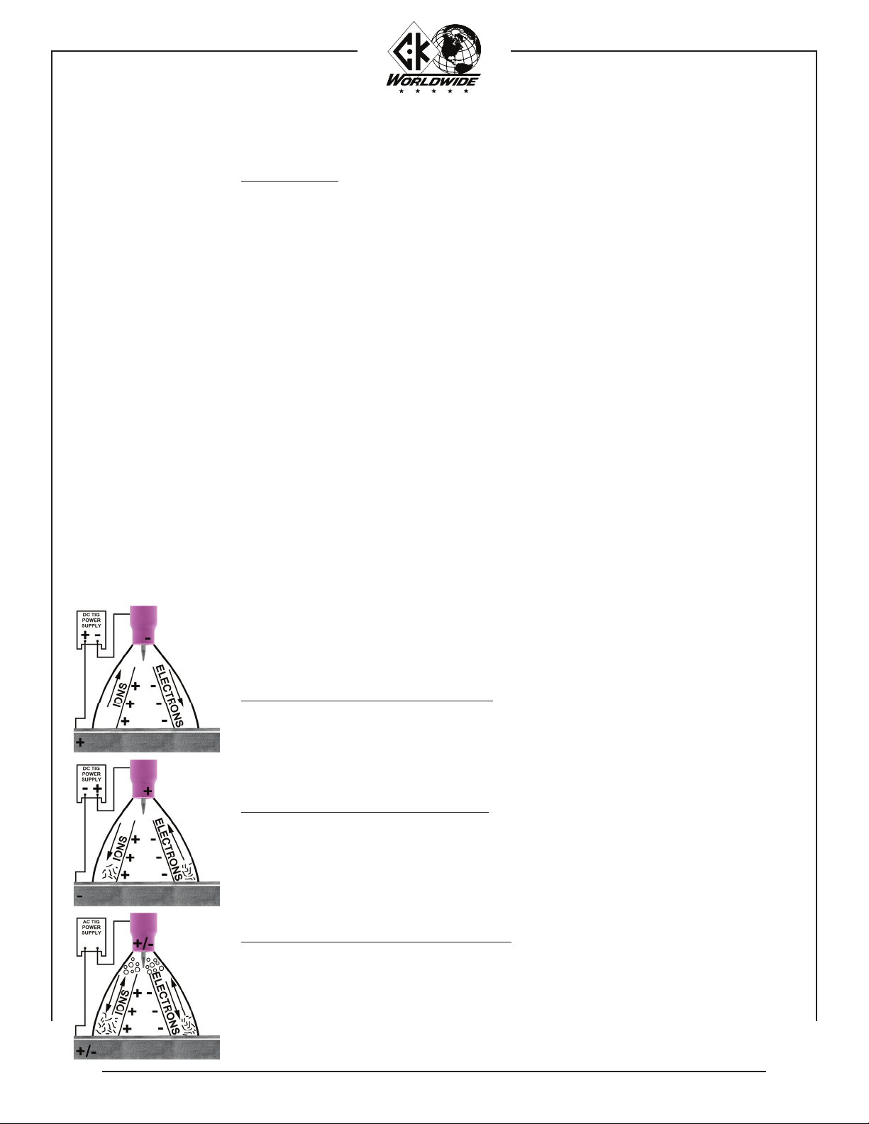
DIRECT CURRENT STRAIGHT POLARITY (DCSP):
DC straight polarity produces the deepest penetration because the heat of the weld is concentrated
at the work or joint. Straight polarity provides no cleaning action (removal of surface oxides). This
polarity is generally used to weld most materials except aluminum and magnesium. May be used
with or without high frequency starting.
DIRECT CURRENT REVERSE POLARITY (DCRP):
DC reverse polarity provides good cleaning action. The combining force of the shielding gas ions
striking the work surface and the fl ow of electrons from the work, cause thesurface oxides to be
broken away. Penetration is shallow because the heat of the weld is concentrated at the electrode.
The use of DCRP is limited to special applications. Maybe used with or without high frequency
starting.
ALTERNATING CURRENT HIGH FREQUENCY (ACHF):
AC combines the good penetration of straight polarity (electrode negative half cycle) and the good
cleaning action of reverse polarity (electrode positive half cycle). Continuous high frequency is
necessary to reestablish the arc which breaks between each half cycle. ACHF current is generally
used to weld aluminum and magnesium.
5

SPECIFICATIONS:
WF5 WIRE FEED UNIT:
Voltage:
Phase:
Frequency:
Height:
Width:
Length:
Weight:
Filler Wire Spool Size:
Filler Wire Sizes:
Wire Feed Speed Range:
Feed Time (pulsed mode):
Dwell Time (pulsed mode):
Delay Start Time (continuous mode):
Wire Retract Time (continuous mode):
HAND TORCHES:
CWH1812 Rating at 100% Duty Cycle:
CWH2312 Rating at 100% Duty Cycle:
CWHTL312 Rating at 100% Duty Cycle:
CWH3512 Rating at 100% Duty Cycle:
Cooling Method:
Torch Cable Length:
Feed Cable Length (soft wire):
Feed Cable Length (hard wire):
115V AC (220V AC 50hz - special item)
Single Phase
50 / 60 hz.
15 in. (38.1cm)
10 in. (25.4cm)
21 in. (53.3cm)
54 lbs. (24.5 kg. )
12 in. (30.5cm)
.023” (.58mm), .030” (.76mm), .035”
(.9mm), .045” (1.1mm), 1/16” (1.6mm)
0-700 in/min (0-1,775cm/min)
continuously variable
continuously variable
continuously variable
continuously variable
180 amp ACHF or DCSP
300 amp ACHF or DCSP
350 amp ACHF or DCSP
400 amp ACHF or DCSP
Water
12-1/2 ft (3.81m)
8 ft. (2.44m)
10 ft. (3.05m)
MACHINE TORCHES*:
CWM2312 Rating at 100% Duty Cycle:
CWM3512 Rating at 100% Duty Cycle:
CWMT412 Rating at 100% Duty Cycle:
CWMT512 Rating at 100% Duty Cycle:
Cooling Method:
Torch Cable Length:
Feed Cable Length (soft wire):
Feed Cable Length (hard wire):
300 amp ACHF or DCSP
400 amp ACHF or DCSP
400 amp ACHF or DCSP
500 amp ACHF or DCSP
Water
12-1/2 ft (3.81m)
8 ft. (2.4m)
10 ft. (3m)
*REMOTE SWITCH REQUIRED:
PART NUMBER: CWMES
See Page 21
6

CHECKLIST:
WF5 Wire Feed Unit
Drive Roll Set - for wire size and type specified (installed)
Torch Outfit with Feed Cable, Wire Guide and Wire Guide
Bracket - model specified at time of order
OPTIONAL
ITEMS:
CWMES:
Remote switch with 11 ft. (3.4m) lead - required for machine torch operation, but
must be ordered as a separate item.
CWH:
Hand held feed assembly and remote switch with 8 ft. (2.4m) feed cable for soft
wire, 10 ft. (3m) feed cable for hard wire.
ITEMS REQUIRED FOR COLD WIRE TIG WELDING NOT PROVIDED:
1. Welding power source - suitable for TIG welding.
2. Water recirculator - for cooling welding torch.
3. Regulator / Flowmeter - for control of shielding gas flows.
4. Shielding gas and cylinders.
5. Full cover welding helmet with proper shaded lens.
6. Leather welding gloves.
7. 12” (30.5cm) spool of welding wire.
INSTALLATION:
8. Ground Cable - sized to suit current range - and ground clamp.
The CK Cold Wire TIG Wire Feed Unit requires 115 volts Alternating Current to
operate. The 115V MUST be supplied by an ISOLATED, GROUNDED outlet. Do not
connect to the 115V AC outlet on the power source. 220V also available.
1. Attach the water cooled power cable of the TIG torch to the electrode terminal on the
power source. A power cable adapter is required to make the proper connection (the
water cooled power cable is the water out line).
2. Attach the ground cable from the power source ground terminal to the work or fixture.
The ground cable should be adequate size and no longer than the torch leads.
3. Attach the torch water in and gas supply hoses to their respective connections points.
4. Plug the feed unit control cord into an isolated, grounded 115V AC outlet. Do not connect feed unit control cord into the 115V AC on the welding power source. For feed
units requiring 220V AC, install an appropriate plug. Then plug the feed unit control cord
into an isolated, grounded 220V AC outlet.
5. Do not set the Cold Wire Feeder directly on the power supply without an insulating
barrier.
7
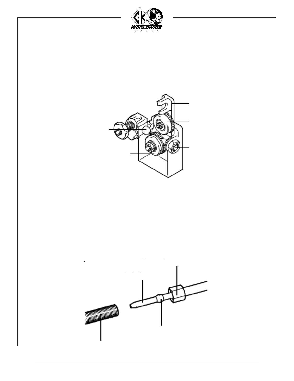
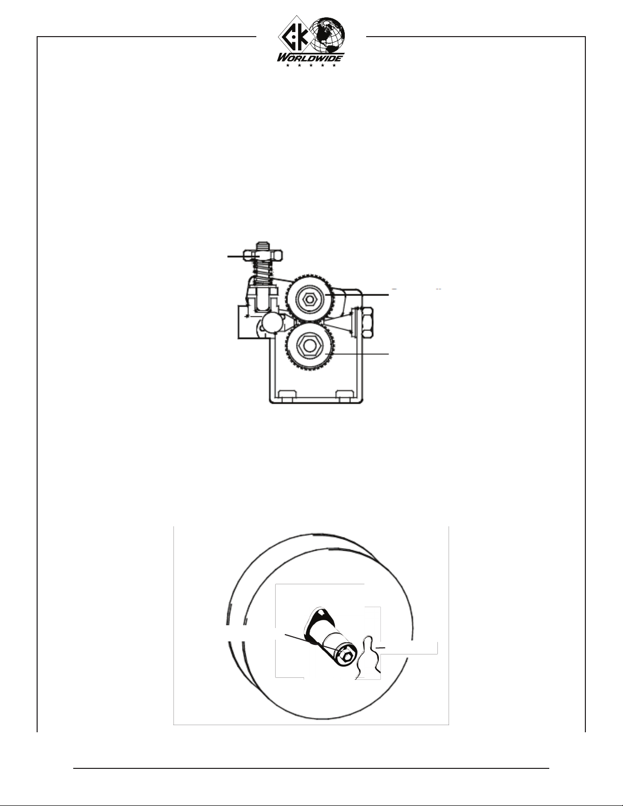
INSTALLATION: FITTING AND THREADING THE FILLER WIRE:
6. Remove the right side Wire Feed Unit cover and install a spool of welding wire. Drive
rolls have two grooves. Check the feed roll to be sure it is on the correct side for the
filler wire being used. See page 21 for drive roll sizes. Unlatch and raise the pressure
roll arm. Thread the wire through the inlet guide to the drive rolls. Feed the wire across
the drive roll groove and into the feed cable inlet guide. Close and relatch the pressure
roll arm.
CAUTION:
Feed Cable Inlet Guide
7. After the wire has been started into the feed cable, straighten feed cable and feed wire
under power by actuating the torch switch. Keep the Feed Cable as straight as possible
and continue pushing the switch until the wire has completely fed through.
CAUTION:
NOTE:
Do not feed wire through the drive rolls under pressure.
Pressure Roll Arm
Pressure Roll
Inlet Guide
Drive Roll
Keep hands away from the wire guide end while feeding
the wire through the feed cable.
When using soft aluminum wire, it may be necessary to
unscrew the compression nut fastening the feed tube to
the wire guide, and manually feed the wire through the
wire guide.
Compression Nut
Feed Tube
Compression Fitting
Wire Guide
8
INSTALLATION: WIRE FEED ROLL ADJUSTMENT:
8. The wire feed rolls and spool brake are properly adjusted at the factory, prior to delivery. As
componenets “seat in”, it may be necessary to adjust the settings.
IMPORTANT:
WARNING:
Pressure Roll
Adjusting Nut
To adjust the feed rolls, tighten the pressure roll adjusting nut
approximately one-half turn past the point where the rolls
just begin to “grab” the welding wire.
Feed rolls that are adjusted too tightly will result in deformed
wire and needless overload of the drive motor.
Pressure Roll
Drive Roll
SPOOL BRAKE ADJUSTMENT:
9. Adjust the spool brake by turning the brake adjusting nut IN to increase braking force and OUT
to decrease the braking force. Adjust the brake just tight enough to prevent the welding wire
from over-running when feeding has stopped.
WARNING:
Spool Brake Adjusting Nut
NOTE:
Too much braking force will needlessly overload the drive
motor.
Retaining Clip - CW804
Always replace and lock the cover door after loading wire.
9

OPERATION:
Direction of Travel
Prior to commencing welding, the following preparations should be made to ensure
optimum performance of the system.
1. Make sure that the pieces of metal to be welded are free of grease, dirt, paint,
and scale. Use a wire brush to remove dirt and scale. Use a stainless steel wire
brush on stainless or aluminum. Paint must be completely removed to bare metal.
Failure to clean the metal properly will result in porous and contaminated welds.
2. Check that the system has been properly installed per the installation instructions.
3. Check the control cable and weld cables for proper connection. Make sure the
ground clamp is firmly attached to a cleaned area on the piece to be welded.
4. Prepare the torch for welding. Check the gas supply and adjust the flowmeter for
the recommended flow rate. Check the water circulator for proper operation.
5. Set the controls on the power source and the Cold Wire TIG Feed Unit.
WELDING:
15°
3-3/4"
Direction of Travel
MAINTENANCE:
With the shield gas flowing, initiate an arc between the tungsten electrode and
the workpiece. When the desired weld pool has formed, depress the switch on the
torch to start the wire feeding. Adjust the Wire Speed and, if in Pulse mode adjust
the Drive time and Dwell time to produce the desired bead.
HAND HELD:
The recommended torch angle for hand held welding is 15° from perpendicular.
The filler wire is fed into the leading edge of the molten pool.
MACHINE:
The recommended torch angle for machine mounting welding is perpendicular. The
filler wire is fed into the leading edge of the molten pool.
1. Blow foreign matter from the feed cable with compressed air before loading a new
spool of welding wire.
2. Replace the wire guide tube if it has been arced, bent, or is badly worn.
10
NOTE:
3. Wire drive motor brushes should be inspected at regular intervals and replaced if
worked to a 1/4” (6.4mm) length.
Whenever a brush is removed for inspection, be sure it is put back in the
same position. It must not be turned around in the brush holder. Excessive
arcing and loss of power will result if it is put back incorrectly.
 Loading...