

Page 1
SpreadNet
®
Model SN914-SZR
RF Single Zone Receiver
Installation Instructions
The SpreadNet® Model SN914-SZR is a Single Zone Receiver in
the C&K family of Spread Spectrum RF products. The SN914-SZR
is a stand-alone product which supports up to 32 SpreadNet transmitters. The SN914-SZR provides both a Form "C" Alarm Relay
output and a Form "A" Trouble Relay output. The SN914-SZR is not
suitable for use with smoke detectors.
Special features include an alarm and trouble event memory. The
SN914-SZR Single Zone Receiver detects alarms, tamper, low battery, and no check-in from the various transmitters (sensors).
Features
• Easy Installation • Up to 32 Devices
• Form "C" Alarm Relay • Individual Device Alarm/
Form "A" Trouble Relay Trouble Indication Using
• EEPROM Memory
• Uses Spacial Diversity
Antennas for Improved • No Check-In and Low Battery
Reception Supervision
• 900 MHz Spread Spectrum • Wall/Cover Tamper
• Noise & RF Immunity • Suitable for UL Grade B
Mounting Location
The RF Receiver may either be mounted on the wall or on the control
panel housing. For optimum performance, the Receiver should be
mounted on the wall. The distance between the Receiver and Control
must not exceed 500 ft. (152.4 m).
Panel
Receiver orientation is not a problem, as the unique antenna design
of the SpreadNet RF Receiver automatically compensates for variations in signal direction. Two antennas orientated at right angles
virtually eliminate problems associated with noise and signal fading.
When choosing a location to install the SN914-SZR RF Receiver,
you should avoid areas near screens, metal window frames, circuit
breaker boxes, metal air conditioner and heater ducts. These areas
interfere with the receiver's ability to pick up signals or are sources
of high noise and radio frequency interference.
500 ft. max.
(152.4 m)
RF Receiver
Removable
Mounting
Tab (Standoff)
Control Panel
Door
Figure 1 - Mounting Location
SN900 Programmer
• Alarm/Trouble Memory
Service
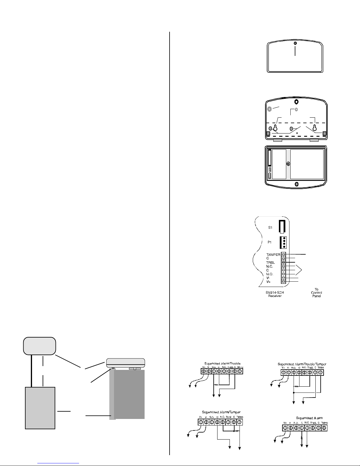
Mounting Procedure
To mount the SN914-SZR, orient
the unit as shown in Figure 2. Loosen
the cover retaining screw on the
front of the Receiver and open the
front panel. The front and rear
Cover Retaining Screw
housings may be separated for easier
installation. Remove the knock-outs
for wiring the Receiver to the control panel.
Use the rear cover as a template
to mark the mounting holes (see
Figure 2). Drill the holes as neces-
Figure 2 - Receiver
Housing
Rear Cover
Wall Tamper
Knock-out
Mounting Wall
sary. The hole at the top center of
the rear housing is designed for
mounting the Receiver to the wall.
The tab also serves as a removable
Mounting Holes
Knock-outs
stand-off when mounting the Receiver to the top of the Control Panel
housing (see Figure 1). The plastic
tab should be removed as it will
interfere with the proper closing of
the control panel door.
Receiver Wall Tamper
Both a cover and a wall tamper are
provided with a single tamper switch.
activate the wall tamper
To
the knock-out in the rear housing
, remove
Front Cover
and install a screw in the wall, leaving enough of the screw head exposed to depress the tamper switch
when the cover is closed.
Wiring the Receiver
Pull the 6-wire cable (common,
Tamper
Switch
power, alarm, and trouble) and
the 2-wire cable (tamper)
through the rear cover. Mount
the Receiver in the desired location as shown in Figure 1.
Connect the SN914-SZR Receiver to the Control Panel as
shown in Figure 3. Be sure to
observe polarity. The SN914SZR derives its power from
Programming
Connector P1
Tamper (Form "B" Relay)
Form "A"
Trouble Relay
Form "C"
Alarm Relay
Common (Panel)
AUX+ (Panel)
the Control Panel via the V+
(to panel AUX+) and V- (to
panel C or GND) terminals. The
SN914-SZR Receiver is elec-
Figure 3 - Wiring the Receiver
tronically protected against reverse polarity.
Relay Configuration
When wiring the SN914-SZR, a number of configurations are available
for connecting and monitoring for Alarm, Tamper, and Trouble conditions. The diagrams below illustrate the proper method of connecting the Receiver to the Control Panel. In each diagram, R represents
the End of Line Resistor.
R
Legend:
Short = Alarm or
Tamper
Open = Trouble
AUX+ Com
(Control Panel)
Legend:
Open = Alarm
AUX+ Com
(Control Panel)
R
Zone Input (Panel)
R
Zone Input (Panel)
Legend:
Short = Alarm
Open = Trouble
AUX+ Com
(Control Panel)
Legend:
Short = Tamper
Open = Alarm
AUX+ Com
(Control Panel)
R
Zone Input (Panel)
Zone Input (Panel)
Page 2
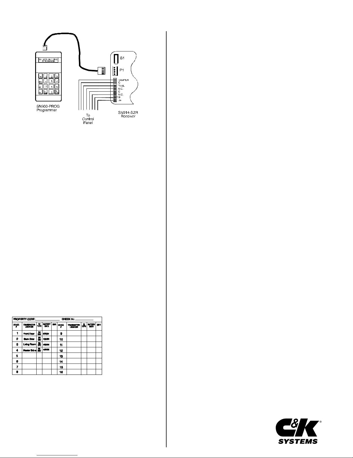
Figure 4 - Connecting the RF Programmer
Programming and Set-Up
The SN914-SZR Receiver is programmed using the SN900-PROG
Handheld Programmer. Connect the SN900-PROG Programmer to
connector P1 on the Receiver, as shown above, using the interconnect cable supplied with the Programmer. In order to determine the
Channel # and Property Code to be used, the Programmer must be
connected to the Receiver prior to programming any of the system's
transmitters.
When selection of the Channel and Property Codes has been successfully completed, the system transmitters may be programmed.
Refer to the Installation Instructions included with each Transmitter
for proper setup.
Programming the Receiver
Program the SN914-SZR Receiver following the instructions outlined in the SN900-PROG RF Programmer Programming Manual.
Testing the Transmitter and Receiver
After the individual transmitters have been installed and programmed,
the RF Programmer can be used with the RF Receiver to measure
transmitter reception characteristics. For additional details, refer to
the SN900-PROG RF Programmer Programming Manual (P/N 5-051136-00).
Termination Summary Label
After the system has been installed, programmed and tested, the
installer should complete the Termination Summary Label, included
with the installation kit. A partial sample of the Termination Label is
shown below with an assortment of zones filled out.
Property Code: Identifies the Transmitter and Receiver as belonging
to a particular system.
Transmitter Location:
The physical location of the
Transmitter within the premises.
TX (Transmitter) Type:
Which of the various
SpreadNet Transmitters is
used in that particular location. (i.e. Door, PIR, Smoke,
etc.)
Check-In Interval: The Supervisory Rate for all Transmitters (in seconds). May range from 30 to
300 seconds in 10 second intervals, or 0 for unsupervised.
SNR: The Signal-to-Noise Ratio of the Transmitter showing Signal
strength and Noise level in decibels (dB).
Battery Date: The date the batteries were installed or last replaced.
Upon completion, the label may then be placed inside the rear cover of the
RF Receiver or inside the Control Panel for future reference.
NOTE: The SN914-SZR Receiver is suitable for UL Grade B service.
Specifications
Power Requirements: Operating Frequency:
210 mA at 9.5 - 14 VDC 902 - 928 MHz Spread Spectrum
Dimensions: Operating Environment:
7.875" x 4.125" x 1.75" 32° to 140° F (0° to 60° C)
(20 cm x 10.5 cm x 4.5 cm) Up to 95% relative humidity
(non-condensing)
Weight:
11 oz. (311 g) Alarm Relay:
Form C, Energized (NC/C/NO)
Trouble Relay: 125 mA, 24 VDC
Form A, Energized (NC)
250 mA, 24 VDC Tamper Relay:
Form B, Energized (NO)
Approvals: 50 mA, 30 VDC
FCC certified
UL listed
IC
FCC NOTICE
The Model SN914-SZR generates and uses radio frequency energy. If not installed and used in
accordance with the manufacturer's instructions, it may cause interference to radio and television
reception. The Receiver has been tested and found to comply with the specifications in Part 15 of FCC
Rules for Class B Computing Devices and FCC Part 15 Subpart C, Specifications for Intentional
Spread Spectrum Radiators.
If this equipment causes interference to radio or television reception - which can be determined by
turning the equipment on and off - the installer is encouraged to correct the interference by one or more
of the following measures: 1) Reorient the antenna of the radio/television. 2) Connect the AC
transformer to a different outlet so the control panel and radio/television are on different branch
circuits. 3) Relocate the control panel with respect to the radio/television.
If necessary, the installer should consult an experienced radio/television technician for additional
suggestions, or send for the "Interference Handbook" prepared by the Federal Communications
Commission. This booklet is available from the U.S. Government Printing Office, Washington D.C.,
20402, stock number 004-000-00450-7.
CAUTION: C&K does not support field changes or modifications to any of the SpreadNet RF
equipment unless they are specifically covered in this manual. All adjustments must be made at the
factory under the specific guidelines set forth in our manufacturing processes. Any modification to the
equipment could void the user's authority to operate the equipment and render the equipment in
violation of FCC Part 15, Subpart C, 15.247.
This device complies with Part 15 of the FCC Rules. Operation is subject to the following two
conditions: (1) this device may not cause harmful interference, and (2) this device must accept any
interference received, including interference that may cause undesired operation.
INDUSTRY CANADA
This digital apparatus does not exceed the Class B limits for radio noise emissions from digital
apparatus as set out in the Radio Interference Regulations of the Canadian Department of
Communications.
Le présent appareil numérque n'émet pas de bruits radioélectriques dépassant les limites applicables
aux appareils numérique de Classe B prescrites dans le règlement sur le brouillage radioélectrique
edicte par le Ministere des Communications du Canada.
LIMITED WARRANTY
Seller warrants its products to be in conformance with its own plans and specifications and to be free
from defects in materials and workmanship under normal use and service for 18 months from the date
stamp control on the product or for products not having a C&K Systems date stamp, for 12 months
from the date of original purchase, unless the installation instructions or catalogue sets forth a shorter
period, in which case the shorter period shall apply. Seller's obligation shall be limited to repairing or
replacing, at its option, free of charge for materials or labor, any part which is proved not in compliance
with Seller's specifications or proves defective in materials or workmanship under normal use and
service. This warranty is void if the product is altered or improperly repaired or serviced by anyone
other than C&K Systems factory service. For warranty service, return the product transportation
prepaid to C&K Factory Service, 107 Woodmere Road, Folsom, CA, 95630.
THERE ARE NO WARRANTIES, EXPRESS OR IMPLIED, OF MERCHANTABILITY OR FITNESS
FOR A PARTICULAR PURPOSE OR OTHERWISE, WHICH EXTEND BEYOND THE DESCRIPTION ON THE FACE HEREOF. In no case shall Seller be liable to anyone for any consequential or
incidental damages for breach of this or any other warranty, express or implied, or upon any other
basis of liability whatsoever, even if the loss or damage is caused by Seller's own negligence or fault.
Seller does not represent that its product may not be compromised or circumvented; that the product
will prevent any personal injury or property loss by burglary, robbery, fire or otherwise; or that the
product will in all cases provide adequate warning or protection. Buyer understands that a properly
installed and maintained alarm may only reduce the risk of burglary, robbery, or fire without warning,
but it is not insurance or a guarantee that such will not occur or that there will be no personal injury
or property loss as a result. CONSEQUENTLY, SELLER SHALL HAVE NO LIABILITY FOR ANY
PERSONAL INJURY, PROPERTY DAMAGE, OR OTHER LOSS BASED ON A CLAIM THAT THE
PRODUCT FAILED TO GIVE WARNING. However, if Seller be held liable, whether directly or
indirectly, for any loss or damage arising under this Limited Warranty or otherwise, regardless of
cause or origin, Seller's maximum liability shall not in any case exceed the purchase price of the
product, which shall be fixed as liquidated damages and not as a penalty, and shall be the complete
and exclusive remedy against Seller.
This warranty replaces all previous warranties and is the only warranty made by C&K Systems on this
product. No increase or alteration, written or verbal, of the obligation of this warranty is authorized.
C&K is a registered trademark of C&K Components, Inc.
SpreadNet is a registered trademark of C&K Systems, Inc.
Copyright 1995 C&K Systems, Inc.
All Rights Reserved
Printed in Hong Kong
P/N 5-051-337-00 Rev A
-2-
 Loading...