

Page 1
SYSTEMS, Inc.
INSTALLATION
INSTRUCTIONS
Model FG-1025Z
Glass-Break Detector
FEATURES
• Advanced microcontroller
with Digital Signal Processing (DSP)
• Precise 160
o
160
o
protected and
excluded zones
• Dual microphones with
time-of-arrival (TOA)
processing
• Continuous self-test
• No adjustments
• No minimum range
• Remote Test Mode activation
with FG-701 simulator
• End-of-line / spare terminals
• Cover and wall tamper
• Selectable Alarm Memory
• LED enable
• 8 - 14 VDC operation
• Energized Form C relay
• PCB and housing designed
to protect against ESD and
mechanical damage
• Watchdog for microcontroller
• Green event LED lights when
sounds are processed
• Dedicated trouble output
• Selectable Command Input
or Remote LED Enable
PRODUCT DESCRIPTION
The FG-1025Z is a directional glass-break detector. Two
microphones and time-of-arrival processing allow the unit to
provide precisely-defined protected and excluded zones.
For a detailed description of how the FG-1025Z works, refer to
the Technical Information section on page 5.
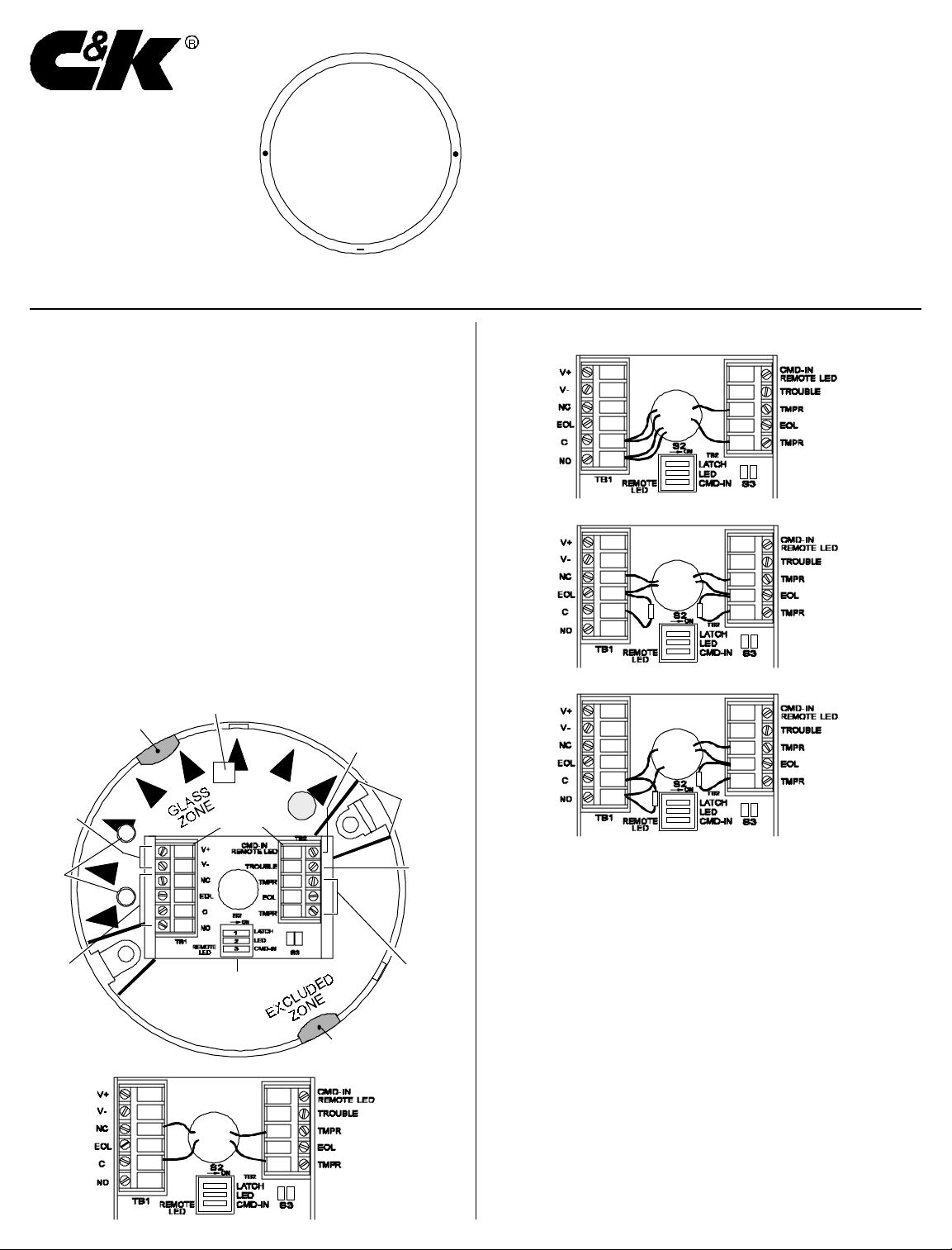
WIRING
1. For surface-wired installation, use optional Wiring Spacer
Plate (model number FG-SP2).
2. Route wire through Wire Entry Hole in the center of the
printed circuit board (PCB), and strip wire ends 1/4" (6.5 mm).
3. Wire the unit as shown, (use 22 - 18 AWG). Reverse polarity
connections will not damage the unit.
4. When wiring is complete, push excess wire back into the
ceiling. (Refer to the Mounting Locations section.)
NOTE: If end-of-line resistors are required, wire as shown in Figures
2c and 2d.
Figure 1
Power
25 mA at
12 VDC
LEDs
Alarm
Form C
125 mA max
25 VDC max
Figure 2
WIRING
Front Microphone
T amper Switch
T e rminal
Blocks
Wire
Entry
Hole
DIP Switch
Command Input
Active low (0-1.5V);
or Remote LED
Select function
at S2-3
Keepout
Zones
Trouble
Output
Open
collector
1K series
resistor
Tamper
25 mA max
24 VDC max
Back
Microphone
WIRING (Continued)
Figure 2b
Wiring for a
N.O. loop, no
EOL resistor
Figure 2c
Wiring for a
N.C. loop with
EOL resistor
Figure 2d
Wiring for a
N.O. loop with
EOL resistor
MOUNTING LOCATION
For the greatest flexibility in aiming the FG-1025Z, mount the unit
on the ceiling. Figure 3 illustrates the protected, excluded and
keepout zones for a ceiling mounted FG-1025Z.
The arrows printed on the intermediate cover (see Figure 1)
indicate the direction of the protected zone. Refer to the
Mounting Guidelines to select an appropriate location, and refer
to the Aiming Guidelines to aim the unit properly. (
mounting is not possible, the unit can be mounted on a wall or post.)
If ceiling
Figure 2a
Wiring for a
N.C. loop, no
EOL resistor
- 1 -
Page 2
MOUNTING LOCATION (Continued)
Figure 3
25' Radius
TOP VIEW
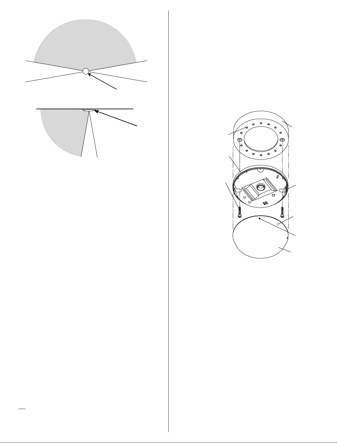
MOUNTING PROCEDURE
NOTE: If you plan to use the ceiling/wall tamper, locate the position
of the ceiling/wall tamper screw before locating the mounting screws.
(Refer to Tamper Switch section.)
PROTECTED
ZONE
o
160
o
EXCLUDED
PROTECTED
ZONE
25' Radius
160
ZONE
20
Keep-
out
Zone
o
o
o
20
Keepout ZoneKeepout Zone 20
FG-1025Z
EXCLUDED
ZONE
SIDE VIEW
FG-1025Z
Mounting Guidelines:
• Mount the unit close to, and within 25' (7.6 m) of the pro-
tected glass.
the excluded zone.
As much of the room as possible should be in
• There is no minimum range, but the unit must have a clear
line-of-sight and a clear view of the protected glass.
• The preferred location is on the ceiling directly opposite the
glass.
• Do not mount in corners, and keep the unit at least 1' (0.3 m)
from any adjacent walls.
• When wall mounting, mount the unit at a height of at least 6 feet
(1.8 m) to avoid accidental screening if furniture in the room is
moved.
• There should be no obstructions on the mounting surface
within 6" (15 cm) of the microphone openings.
• The FG-1025Z will detect through venetian blinds and light
drapes.
window coverings present.
Test the location thoroughly whenever there are
• Do not mount within 3 feet (0.9 m) of forced air ducts, sirens,
or bells measuring two inches (5 cm) or more in diameter.
• Be sure to test the unit for detection in the final mounting
location.
1. To open the sensor, use a screwdriver to push down on the
latch through the slot on the side of the unit. (See Figure 4.)
NOTE: The FG-1025Z is designed to be mounted without removing
the PCB. DO NOT remove the PCB from the protective enclosure.
2. For mounting the FG-1025Z sensor, #6 (M 3.5) or #8 (M 4)
screws are recommended. (Screws are not provided.)
3. If surface wiring is required, use the optional Wiring Spacer
Plate (model number FG-SP2).
Figure 4
The sensor may also be
mounted on the hole
pattern with #8 (M4) selftapping screws
Back Cover
#6 or #8
Mounting Screw
(M 3.5 or M 4)
Note: If required,
the front cover can
be secured with a
screw after
installation. Break
out the cover
screw breakout
flash, and secure
the front cover with
a #4 (M 3) screw.
Optional Wiring
Spacer Plate
(FG-SP2)
Press in on
this latch to
open the unit
Optional
Cover Screw
Breakout Flash
Microphone
Hole
Front Cover
TAMPER SWITCH
The FG-1025Z is equipped with a combination normally-closed
(NC) cover and ceiling/wall tamper. Each unit is shipped with the
cover tamper operational and the ceiling/wall tamper disabled.
Aiming Guidelines:
• Orient the unit so that all protected glass is within the
protected zone and all known false alarm sources are within
the excluded zone. (Refer to Figure 3.)
• Aim the unit so that no protected glass is in the keepout
zones. Sounds in the keepout zone may or may not be
processed. (However, false alarm immunity is at least as
good in the keepout zones as it is in the protected zone.)
• Ver ify the edges of the protected zone by using the FG-701
simulator, hand claps, or any sharp sound. If the sound source
causes the green LED to flicker, the sound is being processed.
(The LEDs must be enabled.)
• Before mounting the unit, refer to the Testing section to help
determine the best location.
Tip: It is a good idea to mount the unit temporarily in the intended
location and power it with a 9 V battery until aiming and testing have
established proper detection. If the 9 V battery cannot supply
sufficient power, the unit will not operate.
To use the wall tamper:
1. Use needle-nose pliers to break out the plastic tab on the
back of the unit. (See Figure 5.) The ceiling/wall tamper arm
will then extend through the hole.
2. The ceiling/wall tamper screw (not provided) should be a flathead #8 (M 4) or #10 (M 5) screw.
3. Install the ceiling/wall tamper screw so that it will just make
contact with the bottom of the tamper cavity when the unit is
mounted. (Refer to Figure 6.)
4. After installing the ceiling/wall tamper screw, position the unit
over it and mark the locations for the mounting screws.
- 2 -
Page 3

TAMPER SWITCH (Continued)
FG-1025Z CONFIGURATION (Continued)
Figure 5
(9.78 mm)
Breakout
Tab
Back
Cover
Figure 6
Tamper
Cavity
.385 in
Rear
Housing
Install screw to seat in tamper
cavity
#8 or #10
Screw
(M 4 or M 5)
CMD IN / REMOTE LED INPUT
Use DIP switch S2-3 to select the function of the control input at
terminal strip TB2. Designate the input as a Command Input or a
Remote LED Enable. The input circuit is shown in Figure 7.
•
As Command Input:
a logic low signal will initiate a complete
self-test sequence. If the test fails, the Trouble Output will be
activated.
•
As a Remote LED Enable:
A logic low signal will enable both
LED's. The manual LED enable at DIP switch S2-2 must be
OFF.
Note: If not used, you can leave the input unconnected.
Figure 7
Command/Remote
LED Input Circuit
TB2
CMD-IN/
Remote LED
Terminal
ACTIVE LOW
INPUT LOW:
INPUT HIGH: 3.5-5V
10K
0-1.5V
+5V
+5V
100K
High-Impedance
TROUBLE OUTPUT
Failure of a power-up or periodic self-test is signaled by a logic
high output at the Trouble Output terminal on TB2. The output
will be held high until a subsequent self-test passes. The output
circuit is shown in Figure 8.
SWITCH OFF ON
LATCH Red alarm LED Red alarm LED
lights for 5 seconds latches ON when
when unit alarms unit alarms
a,b
LED LEDs are disabled LEDs are enabled
except during
power-up test
CMD IN/ TB2 terminal set to TB2 terminal set to
REMOTE Remote LED Enable
c
Command Input
c
LED
Shaded boxes are factory default settings.
a
Latched alarm LED does not affect timing of alarm relay.
b
Reset the alarm LED by removing and restoring power, or by
toggling the S2 LATCH switch off and on.
c
Sets function of CMD-IN/Remote LED terminal.
TESTING
The FG-1025Z should be tested at least once each year. Test
the unit with the FG-701 Glass-Break Simulator. The model FG700 Glass-Break Simulator can be used if it is set for the
TEMPered glass sound. Other glass-break simulators will not
give accurate indication of range.
You must place the FG-1025Z in Test Mode before you can test
the unit.
To activate Test Mode:
1. Stand inside the protected zone within 10 feet (3 m) of the
unit.
NOTE: The FG-1025Z will not respond to simulator sounds from
the excluded zone.
2. Switch the FG-701 to ACTIVATE and MANual modes.
3. Point the front of the simulator at the unit and press the red
start button. (See Figure 9.)
Glass-Break
Detector
Figure 8
Trouble Output
Circuit
TB2
Trouble Output Terminal
20 mA/16 V max
Active High
FG-1025Z CONFIGURA TION
Configure DIP switch S2 to best suit the application:
S2 ON
LATCH
LED
CMD-IN
REMOTE
LED
1
2
3
Red Start
Button
Figure 9
You should hear a shor t buzz from the simulator, and the green
LED on the FG-1025Z should begin flashing about once per
second to indicate it is in Test Mode.
NOTE: In Test Mode the LED disable switch is overridden.
- 3 -
Page 4

TESTING (Continued)
IMPORT ANT: Some environmental factors may reduce the sensor
activation range. If you do not see the green LED flashing after pressing
the red start button, move closer to the unit and try again.
If an FG-701 is not available, or if for any reason remote activation cannot be used, use a screwdriver to short the test pads at
location S3 on the PCB (see Figure 1). This will activ ate Test
Mode. Make sure to replace the front cover of the FG-1025Z
before beginning test.
To test the FG-1025Z:
1. Place the unit in Test Mode as described above.
2. Set the FG-701 switches to the TEST and FLEX positions.
3. Press the red start button. The simulator will "click" on and
start an eight second armed period.
4. Position the FG-701 near the farthest point of the protected
glass and point it directly at the FG-1025Z.
5. Generate a flex signal by carefully striking the glass with a
cushioned tool. The FG-701 will respond by producing a
burst of glass-break audio. (Refer to Figure 10.)
If both the flex and audio are received properly, the red alarm
LED on the FG-1025Z will light.
Glass-Break
Detector
LED Indicators (Continued):
Condition Green LED Red LED
Normal, no event OFF OFF
Normal, event detected Flicker OFF
Normal, break detected OFF ON
Power-up self-test ON, one second ON, one second
Trouble detected Flash ON/OFF Flash OFF/ON
Test mode, no alarm Flash once per second OFF
Test mode, event detected Flicker OFF
Test mode, alarm Flash once per second ON
APPLICATIONS INFORMA TION
The FG-1025Z is designed to detect framed glass broken by an
impact sufficient to make a hole.
To minimize the chance of false alarms:
• Do not use outside.
• Avoid installing in rooms with high-level noise sources, such
as air compressors, bells, power tools, etc., if those sources
can be active when the detector can signal an alarm.
• Test false alarm immunity by activating any known noise
sources in the room.
To maximize detection:
• Mount the unit on a wall or ceiling directly opposite the glass
if possible. The least desirable mounting location is on the
same wall as the glass.
• Minimize range to the glass. Do not install beyond the
maximum specified range even if testing indicates greater
range.
• Verify all installations back to the panel to be sure that the
protection loop is intact.
Red Start
Figure 10
IMPORTANT: If window coverings are present, close them fully and hold
the FG-701 behind the window coverings for testing.
NOTE: You can also use the simulator in the MANual mode to test
audio alone. The blinking green LED on the unit will flicker when
the simulator audio is received correctly. (See the FG-701
Operating Instructions for additional information.)
Button
After testing, exit the Test Mode using the same procedure for
activating the Test Mode. The FG-1025Z also will automatically
exit Test Mode after ten minutes. If the red alarm LED is lit, it will
automatically extinguish upon exiting Test Mode.
LED Indicators:
The two LED's on the front cover are used to indicate the
sensor's operational status. The following table summarizes the
LED operation when the LED's are enabled.
SELF-TESTS
The FG-1025Z automatically performs a series of self-tests
during power-up, and continuously (when the sensor is not
detecting a trouble or alarm condition.) Refer to the chart below
for descriptions of the self-tests performed:
Self-T est Chart
Power-Up Self-Tests
• RAM Test
Write & read all RAM locations
with one's & zero's
• Arithmetic Test
Verify correct results for CPU
arithmetic
• Logic Test
Verify correct results for data
comparisons
• Clock Rate Test
Check clock frequency by
measuring external time
constants
• Active Analog Circuit Test
Inject signals into analog
channels to check gains,
filters, A/D, and interrupts
Continuous Self-Tests
• Watchdog
Supervises microcontroller
• ROM Checksum
Firmware ROM checksum
verified
• RAM Test
Write & read RAM locations
with one's & zero's
• Logic Test
Verify correct results for data
comparisons
• Passive Analog Circuit Test
Verify analog inputs are within
normal bounds
- 4 -
Page 5

SELF-TESTS (Continued)
If any self-test fails, the unit will signal trouble by flashing the LED's
alternately about once per second. Protection will continue if possible. If the trouble condition clears, the LED's will return to the
normal state. Always return the unit for repair if there is any indication of trouble, even if the trouble is temporar y.
TECHNICAL INFORMATION
The FG-1025Z is a directional glass-break detector. It has
precisely-defined protected and excluded zones. There is no
reduction in sensitivity at the edges of the protected zone, and
the device completely rejects sounds in the excluded zone, no
matter how loud they are, or how similar to glass-break they are.
This performance is achieved through the use of two microphones and time-of-arrival (TOA) processing. When a sound is
generated in the room the microphone nearest the sound will
receive it first. The microcontroller in the unit monitors all sound
events received by the microphones and processes only those
received first at the "front" microphone, which is pointed toward
the protected zone. Sounds arriving at the "back" microphone
first are simply ignored.
Because of the symmetry of the unit, the space surrounding the
front and back microphones is divided evenly between protected
and excluded zones. A region 20 degrees wide on each side of
the unit is the keep-out zone. In this region sound may or may
not be processed. Glass to be protected should never be within
the keep-out zone. However, false alarm immunity is at least as
good in the keepout zones as it is in the protected zone.
FCC Notice: This equipment has been tested and found to comply with
the limits for a Class B digital device, pursuant to part 15 of the FCC Rules.
These limits are designed to provide reasonable protection against harmful interference in a residential installation. This equipment generates, uses
and can radiate radio frequency energy and, if not installed and used in
accordance with the instructions, may cause harmful interference to radio
communications. However, there is no guarantee that interference will not
occur in a particular installation. If this equipment does cause harmful
interference to radio or television reception, which can be determined by
turning the equipment off and on, the user is encouraged to tr y to correct
the interference by one or more of the following measures: 1) Reorient or
relocate the receiving antenna, 2) Increase the separation between the
equipment and receiver, 3) Connect the equipment into an outlet on a circuit different from that to which the receiver is connected. The installer can
also consult an experienced radio/television technician for additional suggestions, if necessary.
In addition, a booklet on interference, prepared by the Federal Communications Commission, is also available for reference. Order "Interference
Handbook" from the U.S. Government Printing Office, Washington D.C.
20402, stock no. 0004-000-00450-7.
SPECIFICATIONS
Range:
25' (7.6 m) maximum
No minimum range
Alarm Relay:
Form C
125 mA maximum
25 VDC maximum
Alarm Duration:
5 seconds (unaffected by
alarm LED latching)
Tamper Switc h:
Combination cover and
wall tamper
25 mA maximum
24 VDC maximum
Power Requirements:
8 - 14 VDC; 25 mA typical at
12 VDC, 35 mA max
AC Ripple: 4 Volts peak to peak
at Nominal 12 VDC
Protected Glass:
Minimum size for all types is 11"
(28 cm) square; Glass must be
framed in the wall of the room or
mounted in a barrier of 36" (0.9 m)
minimum width.
Type Minimum Maximum
Plate 3/32" (2.4 mm) 1/4" (6.4 mm)
Tempered 1/8" (3.2 mm) 1/4" (6.4 mm)
Laminated
Wired 1/4" (6.4 mm) 1/4" (6.4 mm)
Coated
Sealed Insulating
1
Laminated and sealed insulating glass types are protected only if both plates of the unit are
broken.
2
For glass coated on the inner surface with 3M scotchshield type RE35NEARL or Hard Glass
Security Film, reduce maximum range to 15 feet (4.6 m).
Patents:
U.S. and International Patents
Applied For
Accessories:
FG-701 Glass-Break Simulator
FG-SP2 Spacer Plate
Note: The FG-1025Z Glass-Break Detector is designed for primary
perimeter security. For a complete security system, additional
interior protection devices are recommended.
1
2
1/8" (3.2 mm) 9/16" (14.3 mm)
1/8" (3.2 mm) 1/4" (6.4 mm)
1
1/8" (3.2 mm) 1/4" (6.4 mm)
Operating Temperature:
o
to 120o F (0o to 49o C)
32
Storage: -4o to 122o F
o
to 50o C)
(-20
RF Immunity:
30 V/m, 10 MHz - 1000 MHz
ESD Immunity:
10 kV;
Discharges of either polarity to
exposed surfaces
Dimensions:
4.25" OD x 0.88" THK
(108 mm x 22.4 mm)
Weight:
4.5 oz., (128 g)
Packaged Product: 7.5 oz, (213 g)
Command Input/
Remote LED Enable:
Active low (0 - 1.5 V)
High impedance for inputs less
than 5.6 V. Draws less than 1 mA
for inputs up to 16 V.
Trouble Output:
Open collector, active high; 1K
series resistor; 20 mA/16 V max
Thickness
Approvals/Listings:
- 5 -
Page 6

Seller warrants its products to be in conformance with its own plans and specifications and to be
free from defects in materials and workmanship under normal use and service for 18 months from
the date stamp control on the product or for products not having a C&K Systems date stamp, for
12 months from the date of original purchase, unless the installation instructions or catalogue sets
forth a shorter period, in which case the shorter period shall apply. Seller's obligation shall be
limited to repairing or replacing, at its option, free of charge for materials or labor, any part which
is proved not in compliance with Seller's specifications or proves defective in materials or
workmanship under normal use and service. This warranty is void if the product is altered or
improperly repaired or serviced by anyone other than C&K Systems factory service. For warranty
service, contact your local C&K Service Center.
THERE ARE NO WARRANTIES, EXPRESS OR IMPLIED, OF MERCHANTABILITY OR FITNESS
FOR A PARTICULAR PURPOSE OR OTHERWISE, WHICH EXTEND BEYOND THE DESCRIPTION ON THE FACE HEREOF. In no case shall Seller be liable to anyone for any consequential
or incidental damages for breach of this or any other warranty, express or implied, or upon any
other basis of liability whatsoever, even if the loss or damage is caused by Seller's own negligence
or fault.
U.S. and International Patents Applied For.
C&K is a registered trademark of C&K Components, Inc.
LIMITED WARRANTY
SYSTEMS, Inc.
Seller does not represent that its product may not be compromised or circumvented; that the
product will prevent any personal injury or property loss by burglary, robbery, fire or otherwise; or
that the product will in all cases provide adequate warning or protection. Buyer understands that
a properly installed and maintained alarm may only reduce the risk of burglary, robbery, or fire
without warning, but it is not insurance or a guarantee that such will not occur or that there will be
no personal injury or property loss as a result. CONSEQUENTLY, SELLER SHALL HAVE NO
LIABILITY FOR ANY PERSONAL INJURY, PROPERTY DAMAGE, OR OTHER LOSS BASED
ON A CLAIM THAT THE PRODUCT FAILED TO GIVE WARNING. However, if Seller be held
liable, whether directly or indirectly, for any loss or damage arising under this Limited Warranty or
otherwise, regardless of cause or origin, Seller's maximum liability shall not in any case exceed
the purchase price of the product, which shall be fixed as liquidated damages and not as a penalty,
and shall be the complete and exclusive remedy against Seller.
This warranty replaces all previous warranties and is the only warranty made by C&K Systems on
this product. No increase or alteration, written or verbal, of the obligation of this warranty is
authorized.
Copyright 1994 C&K Systems, Inc.
All Rights Reserved
5-051-333-00 Rev A
- 6 -
 Loading...