

CKD WKF2, WFK2-005, WFK2-050, WFK2-020, WFK2-250 Series Manual
...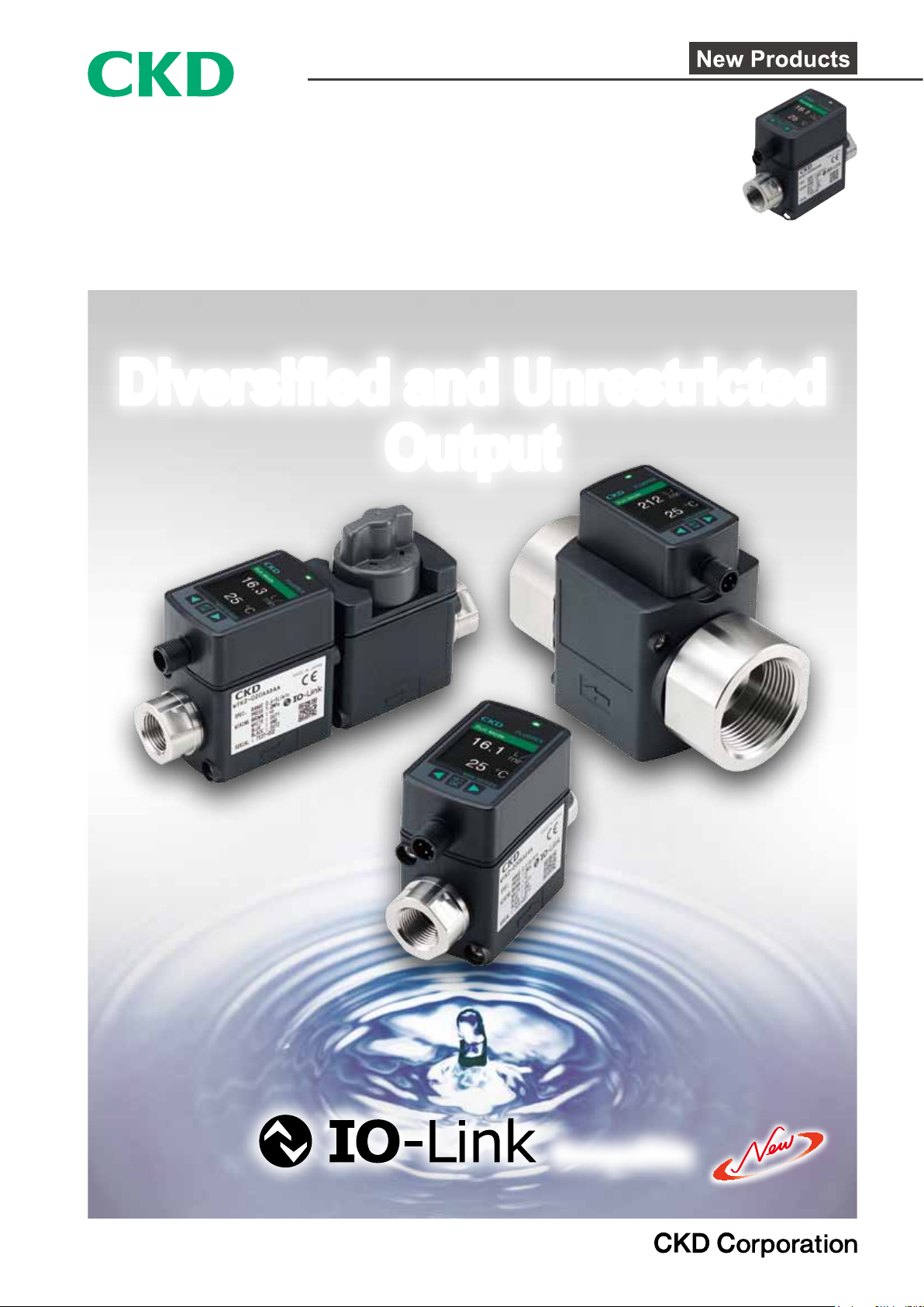
Flow Sensor for Water
WFK2 Series
Diversied and Unrestricted
Output
Compatible
CC-1342A
DIVERSIFIED
Diversified
Peak hold reset
Compatible with ow rates of 0.4 to 250 L/min
Compatible with a wide range of ow rates.
Easy ow rate adjustment
Can be adjusted with a
manual valve.
(option)
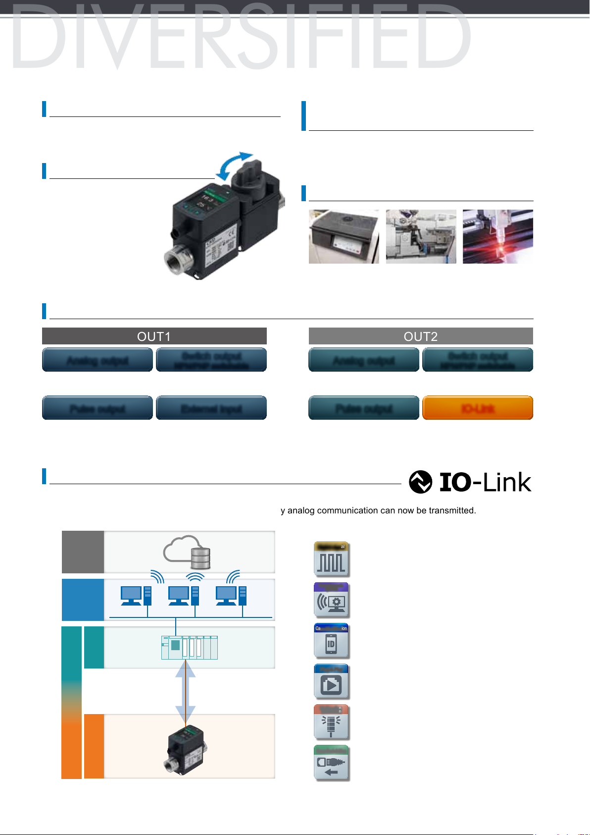
Various output functions available
OUT1 OUT2
Analog output
Instantaneous flow rate
❯
Temperature
❯
Switch output
NPN/PNP switchable
Instantaneous flow rate 1, 2
❯
Temperature 1, 2
❯
Integrating flow
❯
Water temperature measuring feature
is standard for all models
There is no need to for an external water temperature
sensor, reducing space and wiring work.
Handles water up to 95 °C
Molding machine cooling Laser oscillator cooli ngHeated water for mold
Analog output
Instantaneous flow rate
❯
Temperature
❯
temperature controlling
NPN/PNP switchable
Instantaneous flow rate 1, 2
❯
Temperature 1, 2
❯
Integrating flow
❯
Switch output
Pulse output External input
Integrating flow
❯
Integrating flow reset
❯
❯
Pulse output IO-Link
Integrating flow
❯
IO-Link model released
IO-Link is a digital communication standard for factory sensors and actuators. (IEC61131-9)
Parameters and event data that could not be transmitted by analog communication can now be transmitted.
Features of IO-Link
Cloud
Plant
PLC
Case identification
Parameter change
Production site
Ethernet
Permanent monitoring
Alarm notification
Digital signal
Parameter r emote
operation
Case identification
Plug & Play
Malfunction
notification
Permanent monitoring made possible by
digital data.
Parameters can be set and changed from
the network, so the system can be operated
remotely.
Model No. and serial No. can be checked via
the network.
Settings can be copied from the master,
making cumbersome resetting of parameters
during maintenance unnecessary.
Malfunctions and disconnections of the device
can be checked.
I/O
Connection to fieldbus
Connection to an Ethernet network is possible,
enabling the creation of an IoT system.
USER-FRI ENDLY
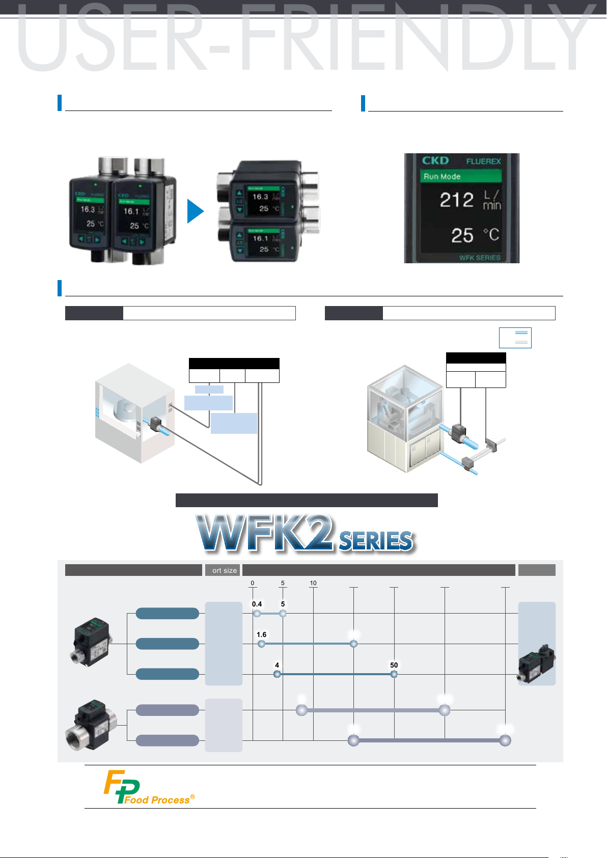
Easier to use
WFK2
Display screen rotation
The liquid crystal display can be rotated in 90° increments without moving the body. There is no interference even when
installed parallel.
Example of applications
Semiconductor
Cooling and temperature control of semiconductor
manufacturing equipment. Etching, grinder, dicer, CVD.
Semiconductor manufacturing equipment
Control equipment
I/O
Communication
Recorder
Monitor (displaying
ow rate)
Detecting abnormalities
Controlling peripheral
Unit
devices
A/D c onversi on
unit
Easy to read 2-screen color liquid crystal display
Set values, temperature, etc., can be displayed
simultaneously.
Hardening Induction hardening device
Quantitative management of
cooling water.
PLC
I/O Unit
Input
Controlling
Output
terminal
solenoid valve
Detect ing abnor mal
terminal
Water
Air
ow rate
Karman vortex ow rate sensor for water FLUEREX
Model variations Port size
WFK2-005
Rc3/8
WFK2-020
WFK2-050
WFK2-100
WFK2-250
Rc1/2
Rc3/4
Rc1
Rc1 1/4
Rc1 1/2
Soleno id valve
Flow rate
measurement data
Water temperature
measurement data
SERIES
Flow rate range (L/min)
0 5 10 20 50 100 250
50.4
1.6
4
8
20
50
20 250
Air operated
valve
100
Option
Manual valve
integration
for easy
flow rate
adjustments
Contact CKD for support for food manufacturing processes FP Series.
FLUEREX (Karman vortex ow rate sensor for water)
WFK2 Series
Flow rate range: 0.4 to 5, 1.6 to 20, 4 to 50, 8 to 100, 20 to 250 L/min
Specications
Descriptions WFK2-005 WFK2-020 WFK2-050 WFK2-100 WFK2-250
Port size Rc, G, NPT 3/8, 1/2, 3/4 1, 1 1/4, 1 1/2
Port material Stainless steel: SUS304
Connection
Applicable uid Pure water, industrial water
Max. working pressure MPa
Proof pressure MPa 1.5
Manual valve internal leakage mL/min
Manual valve allowable
back pressure
Ambient temperature °C 0 to 50 (85% RH or less, no condensation)
Working conditions
Fluid temperature °C 1 to 95
Flow rate range L/min 0.4 to 5 1.6 to 20 4 to 50 8 to 100 20 to 250
Repeatability (*1) Analog accuracy: ±2.5%F.S. Display accuracy: ±2.5%F.S. ±1 digit (min. display unit)
Temperature characteristics (*1)
Low ow cut 5% of F.S.
Integrating ow range 99,999 L or 99,999 m
Flow rate
Integrated pulse rate L/pulse
Pressure loss MPa 0.07 (at F.S.) 0.05 (at F.S.) 0.05 (at F.S.) 0.05 (at F.S.) 0.03 (at F.S.)
Response time (*2) sec 0.25, 0.5, 1, 5, 10 (Initial value 1)
Measurable temperature range
Accuracy
Temperature
Display
Analog output (*3) Standard: 0 to 5 VDC/1 to 5 VDC, option: 4 to 20 mA DC, 0 to 10 VDC/1 to 10 VDC
Switch output NPN or PNP transistor open collector output (can be switched from settings)
Max. load current 50 mA
Output
Max. applied voltage 30 VDC
Internal voltage drop 2.0 V or less
Power supply voltage Analog output standard: 12 to 24 VDC ±10%, analog output option: 24 VDC ±10%
Current consumption (*4) 50 mA or less
Mounting orientation Unrestricted in vertical/horizontal direction
Straight piping section None IN side: 10 D, OUT side: 5 D
Degree of protection IP65 or equiv.
Mounting
Weight g
*1: Accuracy is the average value over 10 sec (for conditions not containing air bubbles). F.S. stands for full scale ow rate.
*2: The time to attain 70% of the original output after the normal ow rate (used) drops instantly to 0.
*3: Check the allowable load on the wiring method page.
*4: Current for when 24 VDC is connected, and no load is applied. The current consumption will vary depending on how the load is connected.
MPa
°C 0 to 100
0.1, 0.5, 1 0.1, 0.5, 1, 10 0.5, 1, 10, 50 1, 10, 50, 100 10, 50, 100
Less than 50: analog accuracy ±2, display accuracy ±2 ±1 digit (min. display unit 1)
50 to 100: analog accuracy ±3, display accuracy ±3 ±1 digit (min. display unit 1)
Two-screen LCD display, instantaneous ow rate: 3 digits, water temperature: 2 digits, integrating ow: 5 digits, with screen rotation
3/8 (Rc, G, NPT): approx. 320
1/2 (Rc, G, NPT): approx. 320
3/4 (Rc, G, NPT): approx. 400
0 No manual valve settings
0.3 No manual valve settings
±5%F.S. (base temperature 25°C, 10 to 50°C)
3
(unit selectable), reset when the power is turned off.
1.0
1 (Rc, G, NPT): approx. 870
1 1/4 (Rc, G, NPT): approx. 1,010
1 1/2 (Rc, G, NPT): approx. 1,100
1
WFK2
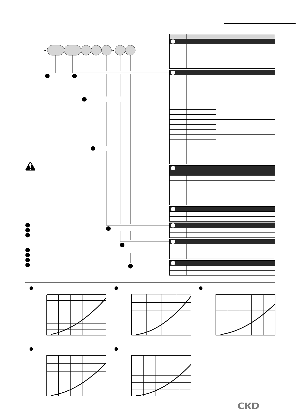
How to order
Series
How to order
AWFK2 A N A C005 AA
A
Flow rate
range
B
Port size
C
IO-Link analog output
D
Display unit
Precautions for model No. selection
*1: The unit display "B" is for overseas use and
cannot be used in Japan.
*2: Option A (with manual valve) has a flow rate
range of 005, 020, or 050 only.
*3: When selecting option A and the bracket (C),
it is a bracket 2 set attachment.
[Example of model No.]
WFK2-005AAAAN-AC
A
Flow rate range : 0.4 to 5 L/min
B
Port size : Rc3/8
C
IO-Link analog output:
Switch/analog output
0 to 5 VDC/1 to 5 VDC
D
Display unit : L/min L m3 °C
E
Manual valve : sensor only
F
Option : standard cable attached
G
Option : attached bracket
E
Manual valve
Pressure loss
F
Option
(attached cable)
G
Bracket
(attached bracket)
Code Content
A
Flow rate range
005 0.4 to 5 L/min
020 1.6 to 20 L/min
050 4.0 to 50 L/min
100 8.0 to 100 L/min
250 20 to 250 L/min
B
Port size
AA Rc3/8
BA Rc1/2
Flow rate range: 005, 020, 050
CA Rc3/4
DA Rc1
Flow rate range: 100, 250EA Rc1 1/4
FA Rc1 1/2
AB G3/8
BB G1/2
Flow rate range: 005, 020, 050
CB G3/4
DB G1
Flow rate range: 100, 250EB G1 1/4
FB G1 1/2
AC NPT3/8
BC NPT1/2
Flow rate range: 005, 020, 050
CC NPT3/4
DC NPT1
EC NPT1 1/4
Flow rate range: 100, 250
FC NPT1 1/2
C
IO-Link analog output
* "D", "E", and "F" have the analog output specications from before IO-Link is used.
A Switch/analog output 0 to 5 VDC/1 to 5 VDC
B Switch/analog output 4 to 20 mA DC
C Switch/analog output 0 to 10 VDC/1 to 10 VDC
D IO-Link compatible 0 to 5 VDC/1 to 5 VDC
E IO-Link compatible 4 to 20 mA DC
F IO-Link compatible 0 to 10 VDC/1 to 10 VDC
D
Display unit
A L/min L m
B L/min us gal/min L m
E
Manual valve
3
°C
3
us gal °C °F *1
N Sensor only
A With manual valve (cock type) *2
F
Option (attached cable)
Blank None
A
Standard cable (M12/4-conductor/ 3 m) attached
B
Double ended connector cable (M12/4-conductor/ 3 m) attached
G
Option (attached bracket)
Blank None
C Attached bracket *3
WFK2-005
0.07
[MPa]
0.06
0.05
0.04
0.03
0.02
Pressure loss
0.01
0.00
0
Flow rate [ℓ/min]
WFK2-100
0.050 0.030
[MPa]
0.040
0.030
0.020
Pressure loss
0.010
0.000
0
20
40
60
80
Flow rate [ℓ/min]
100
WFK2-020
0.05 0.05
[MPa]
0.04 0.04
0.03 0.03
0.02 0.02
Pressure loss
0.01 0.01
0.00
0
5
10
Flow rate [ℓ/min]
15
WFK2-250
0.025
[MPa]
0.020
0.015
0.010
0.005
Pressure loss
0.010
0
50
100
150
Flow rate [ℓ/min]
200 250
20
WFK2-050
[MPa]
Pressure loss
0.00
01
102
203
304
Flow rate [ℓ/min]
40 505
2

WFK2
Series
Internal structure and list
WFK2-005, 020, 050
1
2
3
4
5
6
1
7
2
8
3
9
4
10
5
6
11
WFK2-100, 250
Cannot be disassembled
No. Part name Material
1 Packing FKM Fluoro rubber
2 O-ring FKM Fluoro rubber 2 8 CPU Base 1
3 Temperature sensor SUS316L Thermistor 1 9 Sensor board 1
Karman's vortex street detection sensor
4
5 Attachment SUS304 2 11 Bracket (option) SUS304 or SPCC (1)
6 Sensor body PPS Resin GF40% 1
PPS Resin
Piezoelectric element
* The wetted parts are 2, 3, 4, 5, 6 and 10.
Quantity
No. Part name Material
1 or 2
7 Liquid crystal 1
1 10 O-ring FKM Fluoro rubber 2
7
8
9
10
11
Quantity
WFK2-005, 020, 050****A
1
2
3
4
5
6
7
8
9
10
Cannot be disassembled
No. Part name Material
1 Handle POM Resin 1 7 O-ring FKM Fluoro rubber 2
2 O-ring FKM Fluoro rubber 1
3 Stufng PPS Resin GF40% 1 FKM Fluoro rubber
4 Spacer SUS304 1 9 Attachment SUS304 2
5 O-ring FKM Fluoro rubber 1 10 External case PBT Resin GF30% 1
6 Cock body PPS Resin GF40% 1
* The wetted parts are 2, 3, 4, 5, 6, 7, 8, 9 and 10.
Quantity
No. Part name Material
8 Cock
PPS Resin GF40%
Quantity
1
3
 Loading...