

CKD AX1045T, AX2000T, AX1075T, AX1150T, AX1210T Series Manual
...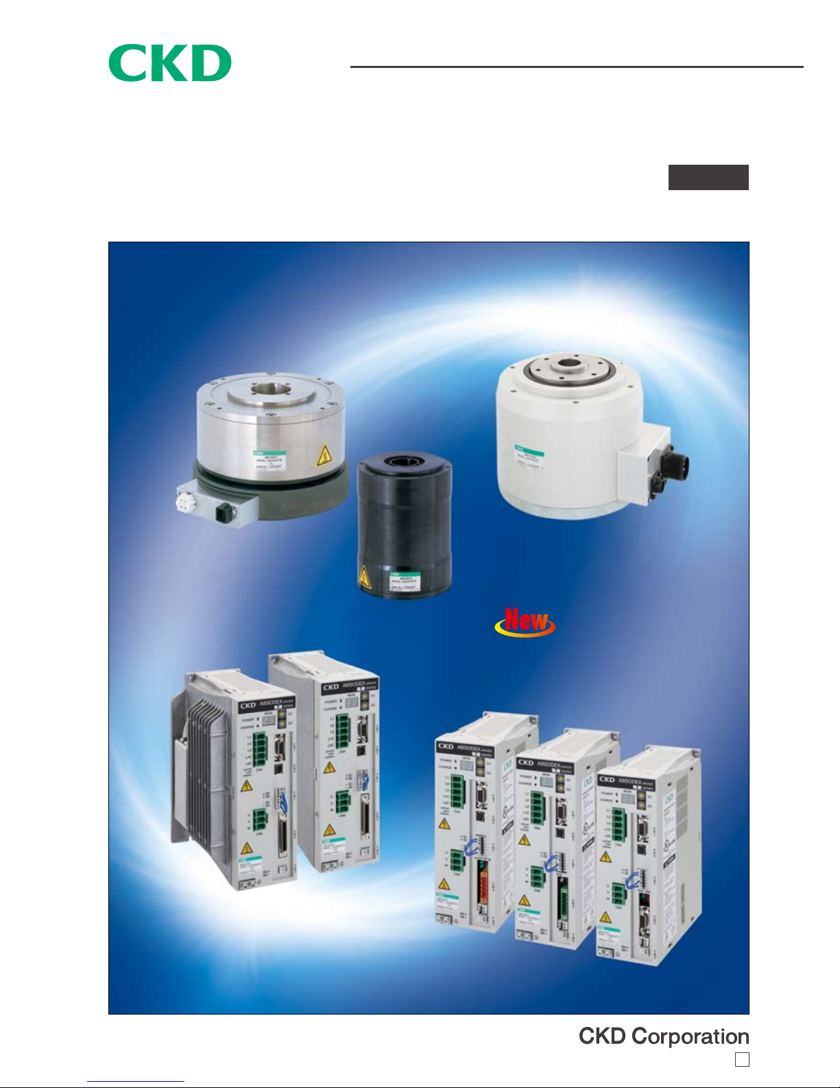
DIRECT DRIVE ACTUATOR, QUICK RESPONSE TYPE, AX1000T, AX2000T, AX4000T SERIES
Quick response type direct drive actuator
"Instantaneous positioning " quick response direct drive actuator
AX1000T, AX2000T or AX4000T series
New product
Use r fri endly driver with
serial communication
CC-Link
DeviceNet
PROFIBUS-DP
CC-995A 4
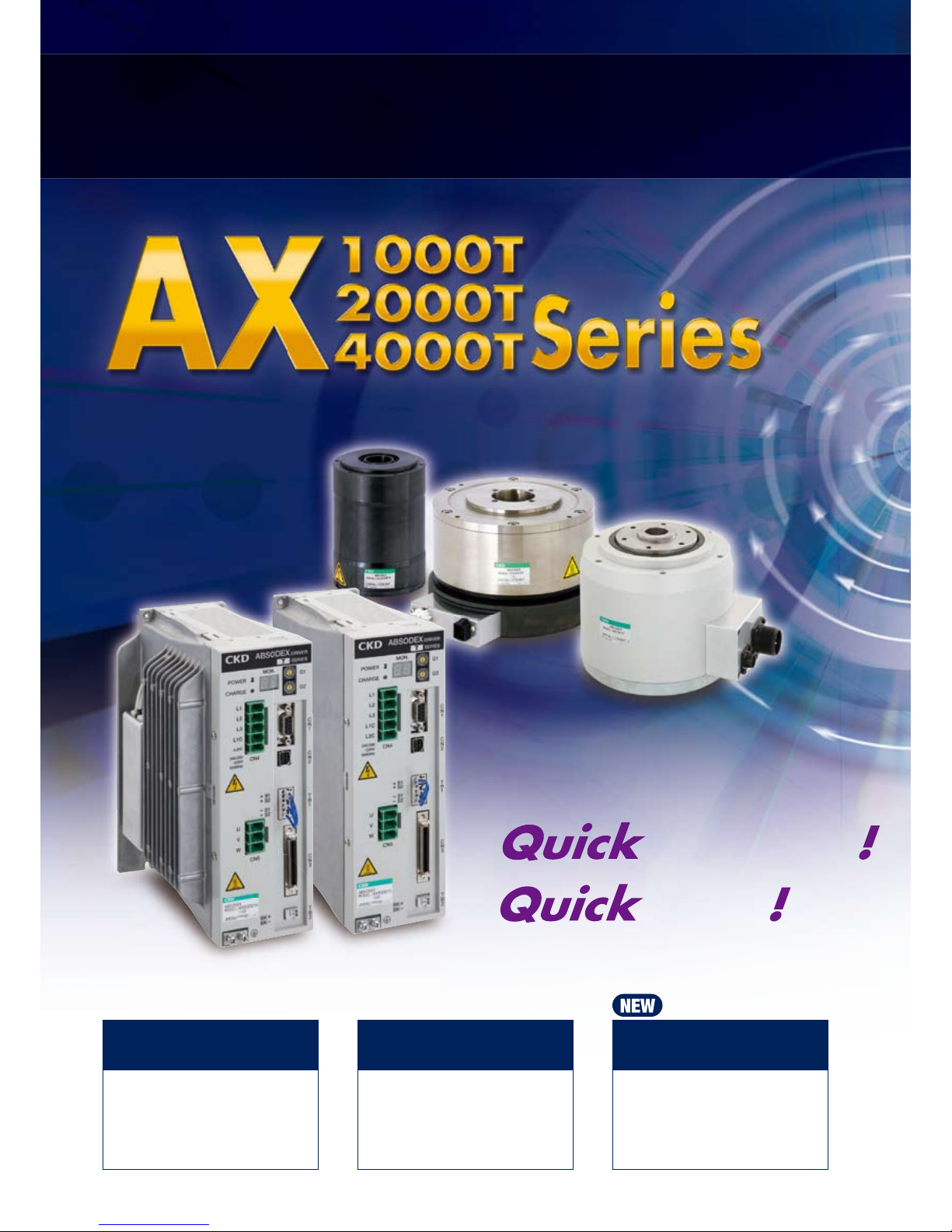
“Instant positioning! Quick response absodex”
with even easier setup!
setup
positioning
High precision,
multi-functions
Environmental design
High precision absolute
DD actuator that can
index 360°anywhere and
combine intermittent and
continuous rotation.
Better compatibility
for AX 1000T
Easier service and
maintenance thanks to
improved compatibility
among drivers, actuators
and cables.
Low profile, oil free,
reusable and energy
efficient....the features
you need to build an
ecological equipment.
1. Shorter tact time for your equipment
Reduce time loss with improved response
”Instant positioning”; positioning time reduced by 75%.
Reduce start up time by linking with peripheral component
Easier to link with other components with the A/B phase encoder output.
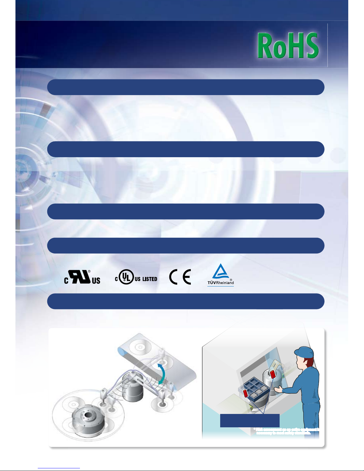
3. Safety standards
IEC standards, category 3 for “safe torque off function”
4. Conformity marks
UL/cUL, CE compliant
2. Improved usability
Optimal tuning in no time
5. Downsized GH/WGH type drivers
65% smaller volume, 50mm shorter depth
Newly added semi-automatic tuning function
Increased I/O signals
Newly added ready output, servo on, etc.
Easier setup
Adjustment software included (AX tools)
Control is on even when the motor is off
Separate motor and control power supply
Reduced tact time with quicker response. Bringing safety by linking to the inspection machine.
Detect the open/close of
the door and shut off power.
* Risk assessment as an entire equipment is
necessary to meet safety standards.
* Risk assessment as an entire equipment is
necessary to meet safety standards.

Intro3
What's new in the TS/TH driver?
Quick response
Improve d respon se and reduced s ta bilization time
wit h the faster CPU allows yo u t o reduce tact time
even further.
Compact and light weight
Footprint of large models with max. output torque of
150N•m ore more has been reduced by 65.
(Compared to CKD's GH type driver)
Due to, light weight was made.
An encoder output is added.
By adding the A-B phase output for current position,
pos i t ion co n trol us i ng p u lse is no w e a s ier an d
certain.
UL/cUL Certified
The actuator is certified by the
following standards.
・
UL1004-1
・
CSA 22.2 No.100
(
File no.
:
E328765
)
Th e dri ver is cer tif ied by the
following standards.
UL508C
CSA 22.2 No.14
(
File no.
:
E325064
)
●Mounting hole eliminates the
task o f u s i n g a m o un t i n g
bracket
● Sepa r a t e m a i n power
supply and control power
supply
It is now possible to cut off
only the main power supply
● 7 segment LED2-digit display
I m p r o v e d v i s i bi li t y a n d
ind i c a t i on o f a l ar m de t a il s
ma k es m a inte nanc e eas i er.
T h e s e t v a l u e f o r g a i n
adjustm ent w ill be s hown on
the LED as well.
● Terminal for safety
Create a power cut off circuit
easily with the STO function.
(safe torque off)
Installation of contactor for cutting
o f f m o t or p o we r is n o l o n ge r
required.
● Connector provided
Easy crimping free wiring.
Ris k s o f el e c t ri c sh o c k
lowered since the terminal
is not exposed.
STO function
compatible drier
Switch Switch
Contactor
Contactor
Safety
Relay unit
Safety
Relay unit
Non-compatible
driver
Supoorted eldbus
Monitor with serial communication
Program no, position and alarm could be m onitored f rom the
PLC.
CC-Link Ver1.10
DeviceNet
PROFIBUS DP
PLC
AX9000TS/TH-U2( U3(U4(
Position
Program n o.
Speed
Alarm, et c.
Start, st op
program s election, etc.
Intro4
Convenience
Additional functions
Input/output function
Ready output
Servo state output
Encoder output
Servo on input
Position deviation counter clear input
Parameter
Setting positioning complete signal output duration
Can be set h 0 to 100ms range.
Mode selection of in position input
Pos i t i on o u t put ON al l th e ti me w i t hin th e in -
position range or ON only when it is stopped within
the in-position range.
Additional program selection method
Select programs with 6bit input (0 to 63)
Operation start with selection input + start input
Reduce tact time by red ucing the time require d to
operate after program selection by abbreviating the
program number setting input.
Prevents free-run when alarm is on
Slows d own and stop s the servo when an a larm
caused by coasting goes off to prevent accidents
■
■
■
■
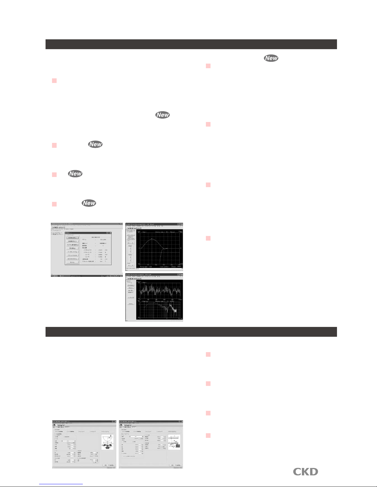
Adjustment and i ns tallation support tool (AX
tools) comes standard.
Get the right adjustments in less time.
Teaching note
Create programs and set parameter
Origin offset
Trial run
Semi-automatic tuning (TS type only)
By adju sting one para meter af ter auto tuning, the
equipment can achieve higher performance.
Speed wave
Review the tuning by measuring the actual change
in velocity and convergent time.
FFT
Deter resonance of mechanisms by setting a notch
filter and low-pass filter.
I/O check
I/O status of host component and can be checked.
■
■
■
■
Features of the Absodex
Green technology
Energy saving
Power is consumed only during indexing. Almost
no powe r is c on su me d while th e outp ut shaft is
stopped.
No need to replace or dispose lubricant
N o m or e t as k of r e pl ac i n g an d d is p o si n g
lu b rica n ts. El imi n ate s poll u tio n caus e d b y oil
leakage.
Smaller components, smaller equipment
Does not require origin detection sensor, reducer
and etc.
Easy to change specifications, reusable
Can be re u s ed u n l i ke m e c h a nica l in d e xes b y
changing specifications using computers and the
teaching pendant.
■
■
■
■
Return to origin not required
Because the absodex has an absolute resolver that can detect the
current position right after being turned on, you don't need to do
an return to origin operatio n each and every time. You can also
restart form the current position after and emergency stop also.
Smooth cam curve drive
5 typ es of cam cur ves a re ins tal led a s sta nda rd.
Minimizes the shock during rotation and stop.
Model selection software (free)
Select the model you need with ease.
Intro5
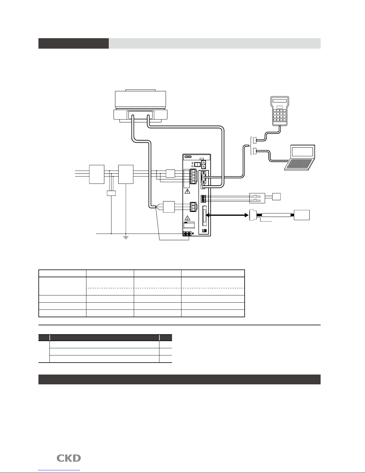
System conguration
Basic settings
1. Input the program from a personal computer or from
the teaching pendant.
2. Set required parameters the same way.
3. Set the appropriate gain.
Basic drive methods
1.
The program which is selected to do wants from PLC.
2. Provide start signal from a PLC.
3. Postioning complete signal will be output from the
driver after a movement.
ABSODEX
+ S2
+ S1
-
- S1
S2
CN5
U
V
W
50/60Hz
- 1 15 V
AC100
CN4
L1
L2C
L1C
L3
L2
CHARGE
P O WE R
T
B
2
C
N
3
T
B
1
C
N
2
C
N
1
G1
G2
DRIVER
SERIES
T
MON.
BK +
BK -
Surge
suppressor
Three phase 200 VAC
GND
Ferrite core
Electromagnetic contactor (any)
Driver
Teaching Pendant
“AX0180” sold separately
PC
Safety
Relay unit
I/O connector
I/O
AX driver power supply
DC24V
PLC
Safety door
switch and etc.,
Noise filter
(Motor cable)
Circuit breaker
(Resolver cable)
Direct drive actuator
Actuator body
CN1
CN2
TB1
CN3
Configuration (set model no. selection)
Name
Quantity
Standard
configuration
Actuator body 1
Driver (with cont roller) 1
Motor cable and r esolver cable
1 each
Accessori es; I/O c onnector, connec tor for p ower supp ly,
connector for moto r cable
Programming tool
Teaching pendant "AX0180" available.
Adjustment and installation support tool (AX tools)
available. (Free, OS:Windows)
Create and save programs, set parameters, enter
commands using a PC.
Communication cable RS-232C(for9 pin D-sub(2m)
model no.:AX-RS232C-9P) is required.
Product name Application Model no. Manufacturer
Noise filter
Three phase/Singl e phase
AC200V to 230V
3SUP-EF10-ER-6
Okaya Electric
Single phase AC100V to 115V
NF2015A-OD Soshin Electri c
Ferrite core Common RC5060 Sos hin Electric
Surge protector Common
R/A/V-81BXZ-4
Okaya Electric
FG clamp* Common FGC-5, FGC-8 Kitagawa Industri es
*FG clamp is used to earth the sheild for motor cable and resolv er cable.
The parts below and over current/short circuit protection components are required to comply with the CE marking.
Also, the driver must be placed withing the switch board. Refer to the manual or technical documents for Absodex
AX Series TS/TH type to find out how to install them.
Note) The communication cable is designed only to
be used for Absodex. If other cables are used, the
drive and pc may be damaged.
Note) Disconnect the te ac hing pe nd ant or PC f rom
CN1 during normal operation. Connect them only
during setting and adjustment.
Note) Do not put the PC in "stand by" with the USB-
Seri al c on version c ab le i s co nnected . This will
result in an error after returning from stand by.
Intro6
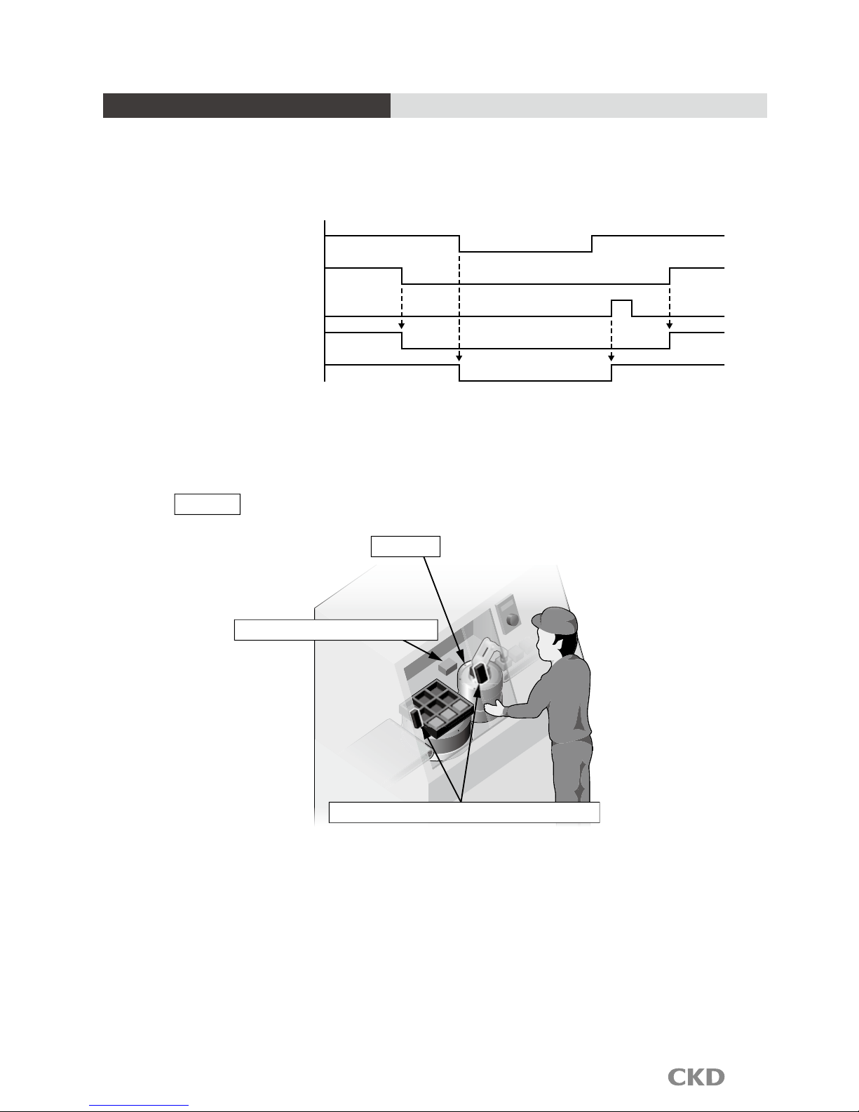
Example of a STO timing chart
The Safe Torque Off function allows you to turn off the motor by the opening/closeing of a contact of
an external safety component.
An example of a timing chart using the STO terminal (TB1) is shown below.
Actuator
Example
Electromagnetic lock, safety door switch
Stop/low speed detection unit
STO Input
Servo ON input
Ready return input
Servo status output
Ready output
Opened contact(STO ineffective)
Servo ON Servo OFF Servo ON
Turns off with STO input
Turns ON with ready return input
(contact with external component)
Closed contact(STO effective) Opened contact(STO ineffective)
Use the safe torque off function with the servo off in normal conditions.
Always conduct a risk assesment off of the entire equipment when using the safe torque off function.
Intro7
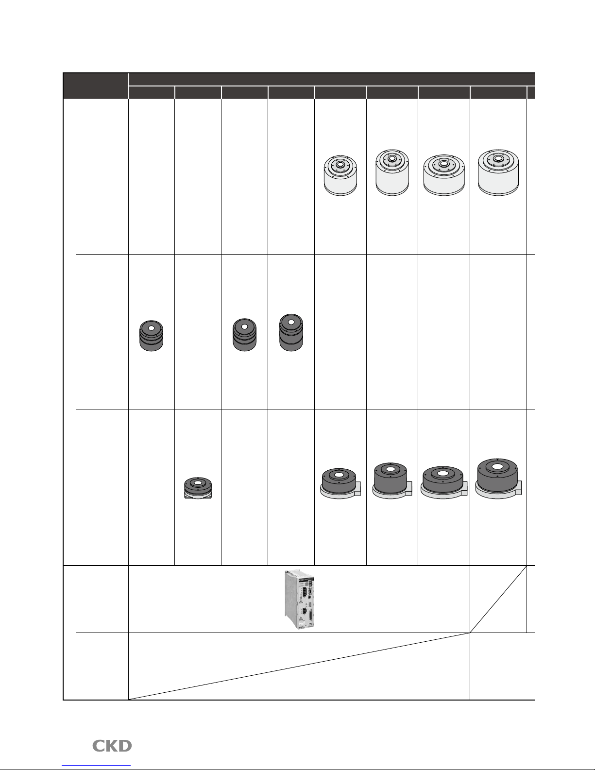
Direct drive actuator series variation
Series
Torque (N•m)
6 9 12 18 22 45 75 150
Actuator
AX1000T
Series
AX1022T AX1045T AX1075T AX1150T
AX2000T
Series
AX2006T AX2012T AX2018T
AX4000T
Series
AX4009T AX4022T AX4045T AX4075T AX4150T
Compatible drier
TS type
Driver
TH type
Driver

Intro8
Torque (N•m)
Index
accuracy
(sec.)
Repeatability
(sec.)
Features
Applications
Page
210 300 500 1000
AX1210T
±15 ±5
High precision
model with
indexing
accuracy and low
displacement
High speed rotation
(AX1022TS:
240rpm,
AX1045TS:240rpm,
AX1075TS:140rpm,
AX1150TS:120rpm,
AX1210TS:120rpm)
Precision
measurment
Turntable
Inspection
machine
Assembly
machine
1
to
6
±30
±5
High speed
rotation (300rpm)
Small diameter
and low profile
Large diameter of
the hollow hole
(Φ30)
P&P
Turntable
Assembly
machine
7
to
10
AX4300T AX4500T AX410WT
±30
±5
High speed
rotation
(AX4009TS:
240rpm,
AX4022TS:240rpm,
AX4045TS:240rpm,
AX4075TS:140rpm)
Capable of
handling load of
large moment of
inertia
Hollow diameter
is wide large size
option.
Turntable
Inspection
machine
Assembly
machine
P&P
11
to
28
One driver can operate actuators of any size
that are compatible.
The controller function enables the actuator's
rotation angle, movement time and timer, etc.,
to be set as desired with an NC program.
Data is exchanged with an external PLC using
M code output, etc.
TS type;29 to 34
TH type; 29 to 34
CableAX1000T AX2000T AX4000T AX0170H
AX9000TS AX9000TH
Applications Page: 41
Safety precautions
: Intro 9
Related parts model no. table
Page: 39
Selection guide Page: 43
Intro9
Always read this section before starting use.
Safety precautions
When de si gn in g and manufacturing d ev ic es using di re ct drive ac tu at or, the ma nu fa ct ur er has an
obligation to manufacture a safe device, an d to c he ck that the sa fe ty of the device's m ec ha ni ca l
mechanism and the system operated by the electrical control that controls the device is secured.
It is important to select, use, handle, and maintain the product appropriately to ensure that the CKD
product is used safely.
Observe warnings and precautions to ensure device safety.
Check that device safety is ensured, and manufacture a safe device.
WARNING
This product is designed and manufactured as a general industrial machine part.
It must be handled by an operator having sufficient knowledge and experience in handling.
Use this product in accordance of specifications.
This product must be used within its stated specifications. It must not be modified or machined.
This product is intended for use as a general-purpose industrial device or part. It is not intended for use outdoors
or for use under the following conditions or environment.
(Note that this produc t can be used when CKD is co nsulted prior to use and t he cu stomer consent s to CKD
product specifications. The customer must provide safety measures to avoid risks in the event of problems.)
Use for special applications including nuclear energy, railway, aircraft, marine vessel, vehicle, medicinal devices,
devices coming into contact with beverages or foodstuffs, amusement devices, emergency cutoff circuits (cutoff,
open, etc.), press machines, press circuits or safety devices.
Use for applications where life or assets could be adversely affected, and special safety measures are required.
Observe association standards and regulations, etc., to ensure safe device design.
Do not remove devices until safety is confirmed.
Inspect and service the machine and devices after confirming safety of the entire system related to this
product.
Note that there may be hot or charged sections even after operation is stopped.
Before starting devi ce inspection or maintenance, tur n o ff devic e power and o ther power to related
devices, release compressed air, and check leakage current.
Observe the In str ucti on M anu al a nd P recauti ons for each pro duct to prev ent
accidents.
Do not rotate the actuator outputs shaft by 30 rpm or more while power is off.
The driver could fail or electrical shock result from actuator power generation.
If the servomotor is turned off (including emergency stop or alarm) or brakes are turned off while a
rotational force, such as gravity is applied, the output shaft may rotate by rotational force.
Conduct these operations flat where rotational force is not applied, or confirm safety before starting.
Unexpected movement may occur during gain adjustment or test operation, so keep hands, etc., away
from the output sh aft. When condu cting operations with the actuato r is not visible, confirm b efore
starting that it is safe even if the output shaft turns.
The brakes of the type with brake do not necessarily hold the outputs shaft completely in all situations.
When safety must be ensured, such as in maintenance with an application that rotates the output shaft
in unbalanced mode, or when stopping the machine for a long time, it may not be sufficient to stop the
shaft with brakes alone. Use the system flat or provide a mechanical lock.
It may take several seconds to stop in an emergency, depending on rotation speed and load.
Observe the precautions to prevent electrical shock.
High voltage is supplied to the terminal block at the driver's front panel. Install the enclosed terminal
cover before operation. Do not touch the terminal block while power is on.
Even af ter the power is turned o ff, a high v ol tage is applied until the charge accumulate d in t he
internal capacitor is discharged. Wait at least five minutes after turning the power off before touching
these sections.
When work ing w ith the side cove r off, such as for main tenance and inspect ion or changi ng driv er
switches, turn the power off to prevent damages and injur ies ca used b y elec trical shock fr om high
voltages.
Do not connect or disconnect connectors while power is on. Misoperation, faults, or electrical shock
may occur.
Before restarting a machine or system, check that measures are taken so that parts
do not come off.
Intro10
Install an over current protection component.
The precautions are ranked as "DANGER", "WARNING" and "CAUTION" in this section.
Note that some items described as “CAUTION” may lead to serious results depending on the situation.
In any case, important information that must be observed is explained.
DANGER:
When a dangerous situation may occur if handling is mistaken leading to fatal or
serious injuries, or when there is a high degree of emergency to a warning.
WARNING:
When a dangerous situation may occur if handling is mistaken leading to fatal or
serious injuries.
CAUTION
When a dangerous situation may occur if handling is mistaken leading to minor
injuries or physical damage.
Observe precautions on the pages that follow to prevent accidents.
Wire according to "JIS B 9960-1: 20 08 S af et y of Machinery - Electrical Equipment of M ac hi nes - Part 1 : General
Requirements", and install an overcurrent protection device (such as molded case circuit breakers and circuit protectors)
to the main•control power (terminal gland no. L1, L2, L3, L1C, L2C) and power supply for I/O (connector no. CN3-DV24V)
(Translation of an excerpt from JIS B9960-1 7.2.1 general requirements)
Overcurrent protection shall be provided in cases where the circuit current in a machine (electrical equipment) can exceed
the lesser of either the rating of a component or allowable ampacity of the conductor. Ratings or settings to be assigned
are set in 7.2.10.
WARRANTY
Scope of warranty
Conditions related to the warranty term and scope are as follows:
1. Term of warranty
This product comes with a 1 year warranty from delivery. (this warranty is effective if the product is not operated
for more than 8 hours a day. The warranty will expire if the product reaches its durability shown below)
Durability (direct drive actuator)
Absodex brake with air brake, piston packing, valves
2. Scope of warranty
If any faults found to be the responsibility of CKD occur during the above warranty term, the part shall
be repaired immediately by CKD free of charge.
Note that the following faults are excluded from the warranty term:
Product abuse/misuse contrary to conditions/environment recommended in its catalogs/specifications.
Faults caused by careless or incorrect handling, or improper control.
Faults caused by factors other than delivered parts.
Faults caused by improper product use.
Faults due to modifications to the product structure , performance, or specifications by a party other
than CKD after the product is delivered, or faults caused by repairs not designated by CKD.
Dam age tha t c oul d hav e b een a voi d ed if th e us er' s mac hin e o r e qu i pm e nt had func tio ns and
structures, etc., considered normal within the industry.
Failure due to causes not foreseeable with the technology at the time of delivery.
Failure due to fires, earthquakes, water damage, lightning, other acts of nature, acts of God, pollution,
salt damage, gas damage, abnormal voltage, or other external forces.
The warrant y he re refers to the warranty of the actually delivered product, and does not inclu de any
damage resulting from a fault in the delivered product.
3. Warranty for exported products
(1) Product returned to our factories or companies/factories designated by CKD will be repaired. CKD is
not liable for the costs and engineering required that is required for the return.
Th i s w arr a nty spec ifi e s b asi c con d iti o ns . If wa rra n ty de tai l s i n i ndi vid u al sp eci f ica t io n dra w ing s or
specifications differ from these warranty conditions, specification drawings or specifications shall take priority.
Intro11
Design & Selection
CAUTION
T h e ac t u a t o r s an d drivers a r e no t waterproof.
Provide waterproofing for use in places where water
or oil could come in contact with these devices.
Current leakag e and fa ults could occur if swarf or
dust get onto the actuator or driver. Check that these
do not come in contact with devices.
Turnin g the main power on and off freque nt ly may
cause damage to the element in the driver.
The output axis may move from the holding position
even
wi th out a n ext ernal f orce if the p ower or ser vo is
turned off.
Optio n a l ma gneti c br a k es a r e us e d to e n h a n ce
holding rigidity during output shaft stoppage.
Do not use these brakes to brake or stop a rotating
output shaft.
Th e a ct uat or and d riv er do not hav e a r us t p ro of
guarantee.
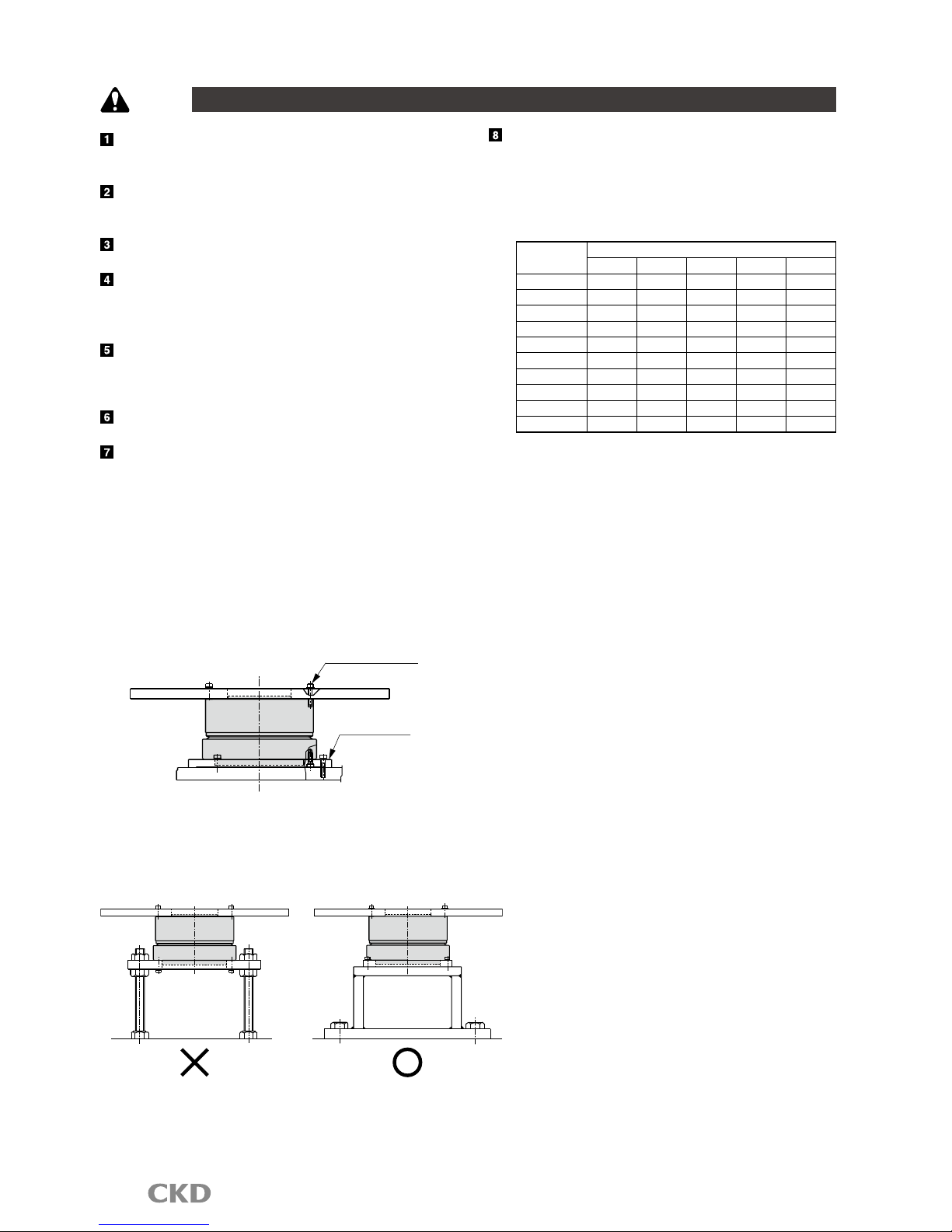
Equipment i n which d i r e c t dr i v e actu a t o r s are
in st alled s ho uld hav e suffi ci ent rig id ity t o rea lize
fu ll dir ec t dri ve act ua tor p er forma nce. If the l oad
equipment o r frame's mechanical u nique vibr at io n
is relati ve ly low (200 t o 300Hz or less), resonance
co uld o ccur in the dir ec t dri ve act uat or and l oad
equipment or frame. Secure the rotary table and main
unit installation bolts, and ensure sufficient rigidity
without loosening, etc. [Fig. 1]
Installing the actuator [Fig.1]
Dial plate fixing
Mounting base
Gain must be adjusted based on load table size, etc.
[F ig .2] Even when the d ir ect drive a ctuator i s not
directly installed, it should be installed on a highly
rigid frame. [Fig.2]
[Fig.2] Mounting the actuator
When extending the outuput shaft, refer to table 1 as
a reference for deciding the extended shaft diameter
and length. Also, install a dummy inertia using fig. 3
as a reference.
[Table1] Reference of diameter for extended output shaft
Max. torque
[N・m]
Shaft extension(mm)
50 100 200 300 500
6 φ35 φ40 φ46 φ50 φ60
9,12 φ40 φ46 φ55 φ60 φ70
18,22 φ45 φ55 φ65 φ70 φ80
45 φ55 φ65 φ75 φ85 φ95
75 φ62 φ75 φ90 φ95 φ110
150 φ75 φ90 φ110 φ115 φ130
210 φ80 φ95 φ115 φ125 φ140
300
φ90 φ105 φ125 φ140 φ155
500 φ100 φ120 φ145 φ160 φ180
1000 φ120 φ140 φ170 φ185 φ210
Intro12
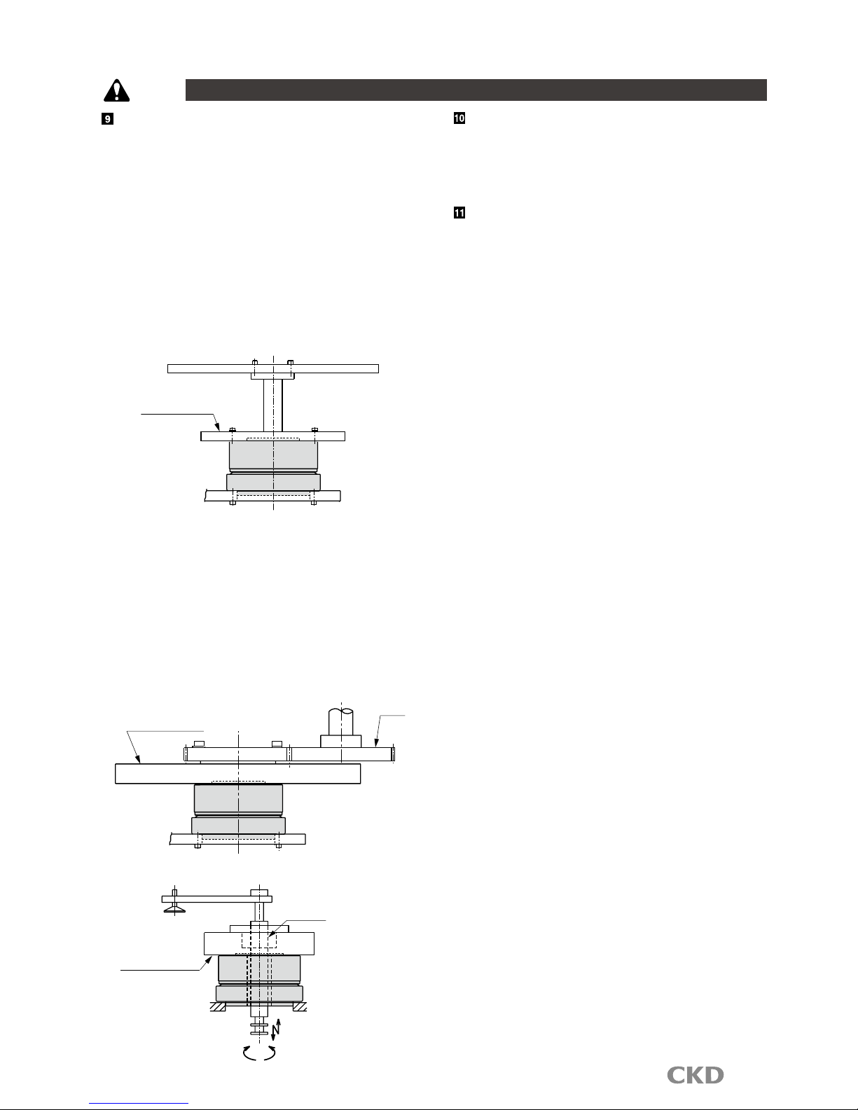
If suff ici e nt rigi dity cann ot be a t tai ned , m a chi ne
r e s o na nc e i s su p p r es s ed t o s o m e d e g re e b y
installing dummy inertia as close to the actuator as
possible.
Examples of adding dummy inertia are shown below.
Wh en exte nd ing the o utp ut shaf t, the fol low ing
dim e n s ions ap p l y as a gu ide to th e extend e d
shaft's diameter:
AX20 06 T, AX4009T, AX2 01 2T, AX2018T, AX □0 22T,
AX □ 045 T:Φ6 0 mm an d o ver, AX□0 7 5T, A X□15 0T,
AX 1 210T, A X43 0 0T:Φ 90m m and ov er, AX4 5 00T:
Φ150mm and over.
As a reference, dummy inertia is [load inertia] x (0.2
to 1). [Fig.3]
[Fig.3] Example 1. for dummy inertia installation
Dummy inertia
When coupling with belts, gears or spline or when
joining with a key, dummy inertia should be [load
inertia] x (0.5 to 2).
If spe e d c han ges wit h b e lts or gear s, use load
in ert ia as the act uat or outp ut sha ft con ver sio n
value , and install dummy inertia on t he ac tuator.
[fig.4] [fig.5].
Note: Inst al l dummy inertia as l ar ge as possible
wi thin the a ctu ator' s cap ac ity. ( Use ste el
with a large specific gravity).
[Fig.4] Example 2. for dummy inertia installation
Dummy inertia
Gear
[Fig.5] Example 3. for dummy inertia installation
Dummy inertia
Ball spline
( )
Select gears with as large
diameters as possible.
Design & Selection
CAUTION
Do not place the actuator where it may contact strong
magnetic field.
Do not pass cables with high voltage through the
central hollow hole.
It may lead to malfunctioning, lower performance and
damage.
Use of sur ge protector is recommended when there
is a risk of damage caused by lightning surge.

Intro13
Design & Selection
CAUTION
Connecting magnetic brakes
24 VDC (relay drive)
24 VDC (power supply for)
Surge
Protector
200 VAC three phase
Blue lead wire
(Not polarized)
GND
Ferrite core
Relay
Electromagnetic contactor (any)
Driver
Protection element
(Included with actuator)
(Resolver cable)
Direct drive actuator
Actuator body
Noise filter
(Motor cable)
Cut off machine for wiring
G2
G1
SERIES
C
N
1
DRIVER
C
N
2
T
B
1
C
N
3
T
B
2
POWER
CHARGE
L2
L3
L1C
L2C
L1
CN4
AC100
-115V
50/60Hz
W
V
U
CN5
- S1
BK +
BK -
- S2
ABSODEX
+ S1
+ S2
MON.
AB S O D E X
MODEL: AX9000TS
MADE IN JAPAN
㧿㧱㧾㧵㧭㧸㧦+25A1+25A1+25A1+25A1+25A1+25A1+25A1
CKD Corporation
1) Do not use magnetic brakes to stop or control the rotating output shaft.
2) The driver will be damaged if the driver's BK+ and BK- and magnetic brakes are directly connected.
3) When connecting the following inductive load, such as a relay, to the external contact, set the coil's rated voltage to 24
VDC and the rated current to 100 mA or less, and provide measures against surge current.
Recommended circuit for magnetic brakes
( )
Driver
BK-
BK +
(not included)
External contact (such as relay)
(not included)
Surge countermeasures (such as diodes)
(Blue Approx. 30 cm)
Electromagnetic brake lead wire
(not included)
External power 24 VDC
(not included)
External power 24 VDC
CR
Protection element
Electromagnetic brake
Attached to
actuator
Driver
BK-
BK +
(not included)
Relay (4 pole)
(not included)
Surge such as countermeasures (such as diode)
(Approximate blue 30cm)
Lead wire
(not included)
External power 24 VDC
(not included)
External power 24 VDC
CR
Protection element
Electromagnetic brake
( )
Attached to
actuator
• Relay contact serial connection
Operation method
1. Control with N C program (M68, M69)
When the "M68" cod e is executed , BK+ to BK- will not be
energized (brakes are applied), a nd when the "M69" code
is
executed, BK+ to BK- will be en ergized (brakes are
released).
2. Control with b rake release input (I/O connec tor/18 pin)
If brake releas e is inpu t while the brakes are applied, BK+
to BK- will be en ergized (brakes are released).
If magnetic brake s ar e frequently turned on and off, use a
solid-state relay (SSR) for the external contac t.
Recommended model G3NA-D210BDC 5-24 (OMRON)
Refer to the SSR instruction manual before usin g.
Check that relay contact capacity is 10 times or more th an
the rated cur rent. If less , use a mu ltiple relay and use two
or more relay con tacts serially. Reed lif e can be extended.
When passing a shaft through the hollow hole in th e type wi th magnetic brakes, use a non-mag netic material
(SUS303, etc.).
If magnetic material (S45C, etc.) is used, the shaft will be magnetized. This could cause iron powder to stick on the
device or the peripheral devices to be affected by the magnetic properties.
No te t hat aro und the m ag netic b rakes , iro n powde r, etc ., could b e att racte d by the m agnet ic p roper ties, o r
measuring instruments, sensors and other devices could be affected.
Refer to the Technical Documents of the Absodex AX Series TS,TH type driver for other precautions.
Intro14
Safety precautions
Always read this section before starting use.
Labor saving mechanisms warning
Installation & Adjustment
CAUTION
Co nnect the e nc losed cab le b etween the act ua tor
and driver. Check that excessive force is not applied
an d the cab le is not dam aged. D o not m od ify t he
enc l o s ed c a b l e (c hang e th e length or ma t erial )
because this could cause malfunction or faults.
Con nec t t he cor r ect p owe r s upp ly. Conn ect ing a
undesignated power supply could cause faults. Wait
at l eas t 5 sec onds after tur nin g pow er off b efore
turning it on again.
Securely fix the direct drive actuator to the machine,
and securely install loads s uch as the table before
adjust ing ga in. Confirm that no interference occurs
and th a t sa f e t y is se c u r e d ev e n when fl e x i b l e
sections are rotated.
Do no t tap th e outp u t s h aft wi th a hamm e r, nor
assembl e it f orcibly. Failure to o bs erve th is would
pr eve nt the exp ect ed accu rac y or func tio ns, a nd
could cause faults.
Do n ot place s trong m agnet ic field s suc h as rar e
earth magnets near the actuator. Failure to observ e
th i s may ca u s e f a i l u r e s to m a i n t a in ex p e c t e d
accuracy.
T h e ac t u a t or ma y b e c o me ho t dep e n d i n g on
operating conditions. Provide a cover, etc., so that it
will not be touched by accident.
T h e a c tu at o r m a y b e co me h o t d e p en di n g o n
operating conditions.
Do not d ril l holes int o the a ctuat or. Con tact CKD
when machining is required.
Do not get on the actuator or flexible parts such the
rotary table on the actuator during maintenance, etc.
Compatible type
If the actuator and driver are combined mistakenly
af t er prog ram inp u t ( par ame t er sett ing ) , a lar m
3 wi l l go of f . Ch e c k the ac t u a t o r and dr i v e r
combination.
No t e: Alar m 3 is t o p r eve n t m a lfu ncti on i f t he
actuator and driver c om bi na tion d if fe r from
when the program was input. Alarm 3 is reset
when the program and parameter s are input
again.
If operation is started with an i ncorrec t actu ator
and d r i v e r comb i n a t i o n af t e r the p r o g r a m is
in put ( after p ara meter s ett ing), it may res ult i n
malfunctions and damages.
When changing the cable length or type, order the
cable separately.
Actuator may catch fire if an incompatible driver is
connected.
Wh en using a c ir cuit break er, selec t one that has
higher harmonic measures for inverter use.
The posit i on of the ou tpu t shaf t in th e a c tuat o r
dimension drawi ng does not indicate the actuator's
origin. W hen usin g it at the output shaft sh ow n in
dimension drawings, the origin must be adjusted to
the origin offset.
The body outlet cable on AX4009T and AX200T series
ca n not b e mov ed. Alw ays f ix it at the c onn ect or
section so that it w il l not move. A ls o, refrai n from
apply ing e xcess force onto th e cable or pulling on
the cable since it may damage it.
Re fer t o the tec hn ica l doc ume nt s of the Abxod ex
AX Ser ies TS, T H t ype f or othe r pre cau tio ns and
conformity to standards
.
During Use & Maintenance
CAUTION
Do not di sassemble the actuator, because this may
compromise ex pecte d functions an d accuracy. Any
mo difi cat ion to the resol ver cou ld caus e c r iti cal
damage.
Wh en testing withstand voltage of the machine or
equ i p ment co ntai n i ng th e direc t drive ac t uato r,
disconnect the power cable for the driver and check
that the voltage is not applied to the driver. Failure to
observe this could result in faults.
If al arm " 4" (a ctuator over load: electr onic thermal )
goes off, wa it fo r the actuato r temperatu re to drop
before restarting.
Ala rm "4" could occur in the cases below. Remo ve
the cause before resuming use.
R e s on an ce o r v i b ra ti on : E n s ur e s u f fi ci en t
installation rigidity.
Ta c t or sp e e d : In c r e a s e m o v e m e nt tim e or
stopping time.
St ru cture tha t loc ks t he outpu t sha ft : Add M68,
M69 commands.
Actua tor coor dinates are recognize d after power is
turned on so c heck that the outp ut shaft do es not
move for several seconds after power is turned on.
Re fer t o the tec hn ica l doc ume nt s of the Abxod ex
AX Ser ies TS, T H t ype f or othe r pre cau tio ns and
conformity to standards
.
1
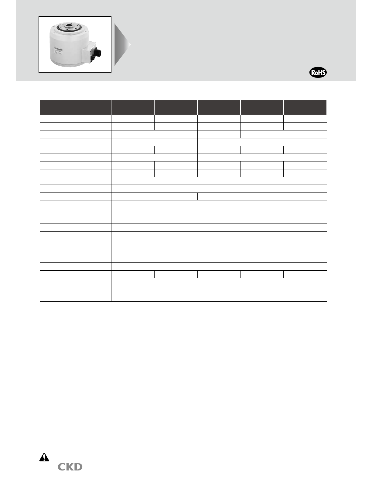
Actuator specifications
Direct drive actuator
AX1000T
Series
actuator
High precision specification with
high indexing accuracy and output shaft run out
Max. torque: 22, 45/75/150/210N•m
Descriptions AX1022T AX1045T AX1075T AX1150T AX1210T
Maximum output torque
N•m 22 45 75 150 210
Continuous output torque
N•m 7 15 25 50 70
Max. rotation speed rpm 240 (Note 1) 140 (Note 1) 120 (Note 1)
Allowable axial load N 600 2200
Allowable moment load
N•m 19 38 70 140 170
Allowable radial load N 1000 4000
Output shaft moment of inertia
kg/m
2
0.00505 0.00790 0.03660 0.05820 0.09280
Allowable load moment of inertia
kg/m
2
0.6 0.9 4.0 6.0 10.0
Index accuracy (Note 3)
sec. ±15
Repeatability (Note 3)
sec. ±5
Output shaft friction torque
N•m 2.0 8.0
Resolver resolution P/rev 540672
Motor isolations class Class F
Motor withstanding voltage
1500 VAC for one minute
Motor isolation resistance
10MΩ 500 VDC and over
Working ambient temperature range
0 to 45°C
Ambient humidity range
20 to 85%RH with no dew condensation
Storage ambient temperature range
-20 to 80°C
Storage ambient humidity range
20 to 90%RH with no dew condensation
Atmosphere No corrosive gas, flammable or powder dust
Weight kg 8.9 12.0 23.0 32.0 44.0
Run out of output shaft
mm 0.01
Run out of output shaft
surface
mm 0.01
Protection IP20
Note1: The speed must be kept below 80rpm during continuous rotation.
Contact CKD for CE certification requirements.
Note2: Refer to "Technical explanations" on page 49 for the details on index accuracy and repeatability.
Note3: The max ambient temperature is 40°C if used as an UL certified product.
Always read the precautions on Intro 9 to 13 before starting use.
2
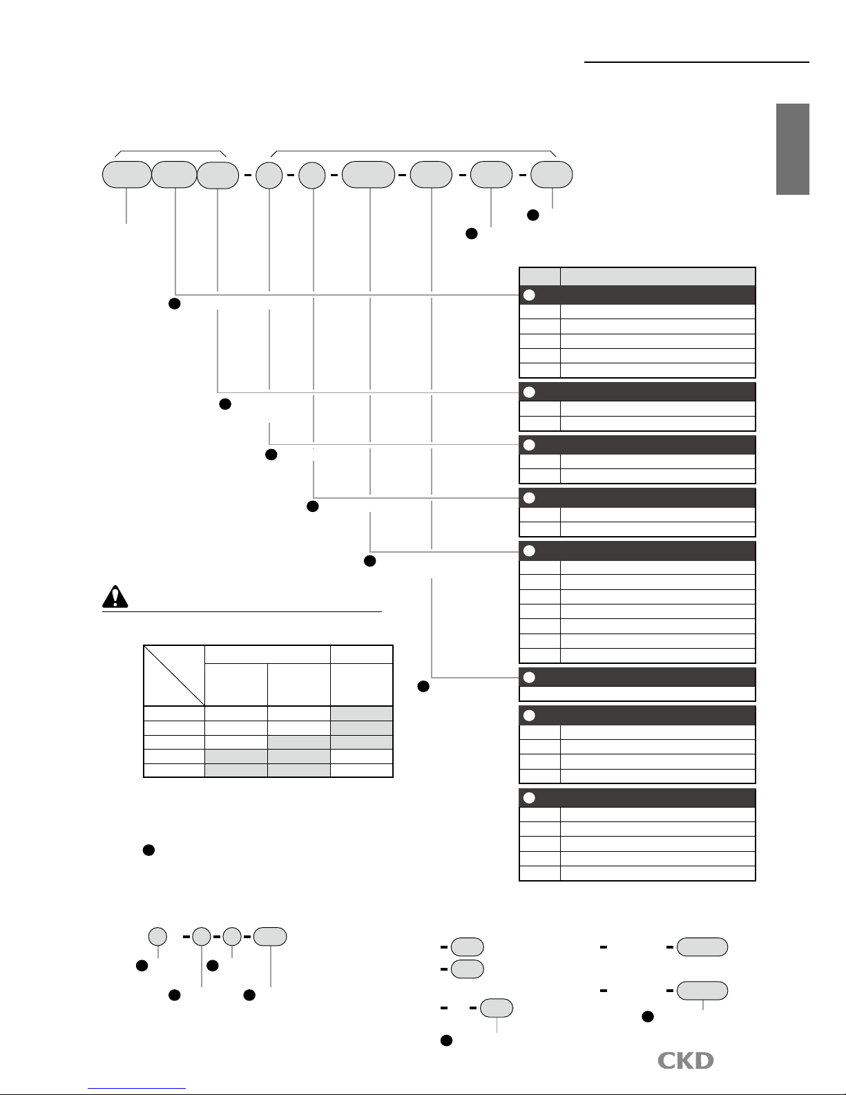
How to order
AX1000T
Series
AX1000T
Actuator
H
Interface specifications
H
Interface specifications
How to order
G
Dowel hole
Note 4
E
Cable length
Note 3
B
Driver type
Note 1
Model no.
A
Size (max. torque)
D
Connector direction
Note on model no. selection
Note 1:
Use the table below to select the appropriate driver.
Driver-power voltage table
Driver
Type
Model
TS type driver
TH type driver
Three phase/
single phase
200 to 230 VAC
Single
phase 100
to 115 VAC
Three
phase 200
to 230 VAC
AX1022T
Blank Note 2
J1
AX1045T
Blank Note 2
J1
AX1075T
Blank Note 2
AX1150T Blank
AX1210T Blank
Note 2: Single phase 200 to 230 VAC is available for
models with a torque of 45N•m or less.
Note 3:
Flexible cable
Refer to page 35 for the dimensions of the cable.
Note 4: CIf the mounting base is "B" (with blackened
mounting base), "P2" and "P3" can not be
selected.
Model Model no. of options
AX1 DM04022 B J1 P1 U0CTS
Symbol
Descriptions
A
Size (max. torque)
022 22 N•m
045 45 N•m
075 75 N•m
150 150N•m
210 210N•m
B
Driver type
TS TS type driver
TH TH type driver
C
Mounting base
Blank Standard (without mounting base)
B With blackened mounting base
E
Cable length
DM02 2m
DM04 4m (standard length)
DM06 6m
DM08 8m
DM10 10m
DM15 15m
DM20 20m
G
Dowel hole
Blank Standard (without dowel hole)
P1 1 on top
P2 1 on bottom
P3
1 each on both top and bottom
F
Driver power voltage
Refer to the Driver-power voltage table on the left.
F
Driver power
voltage Note 1
D
Connector direction
Blank
Standard (connector horizontal installation)
C Connector bottom installation
C
Mounting base
( )
Discrete actuator body model no.
Discrete driver model no.
Discrete cable model no.
AX1 T C P1 B
AX9000TS
AX9000TH
U0
U0
AX9000TS J1 U0
AX CBLM5 DM04
Three phase 200 to 230 VAC
Single phase 100 to 115 VAC
A
Size
C
Mounting base
D
Connector
direction
G
Dowel
hole
E
Cable change
Note: "04" for cable
length 4 m
Motor cable
AX CBLR5 DM04
Resolver cable
Set model no. (actuator, driver or cable)
H
Interface specifications
U0 Parallel I/O (NPN specifications)
U1
Parallel I/O (PNP specications)(Coming soon)
U2 CC-Link
U3
PROFIBUS-DP
U4 DeviceNet
*Custom orders are not CE, UL/cUL, RoHS certified. Consult with CKD for details.
3
AX1000T
Series
F
F
L
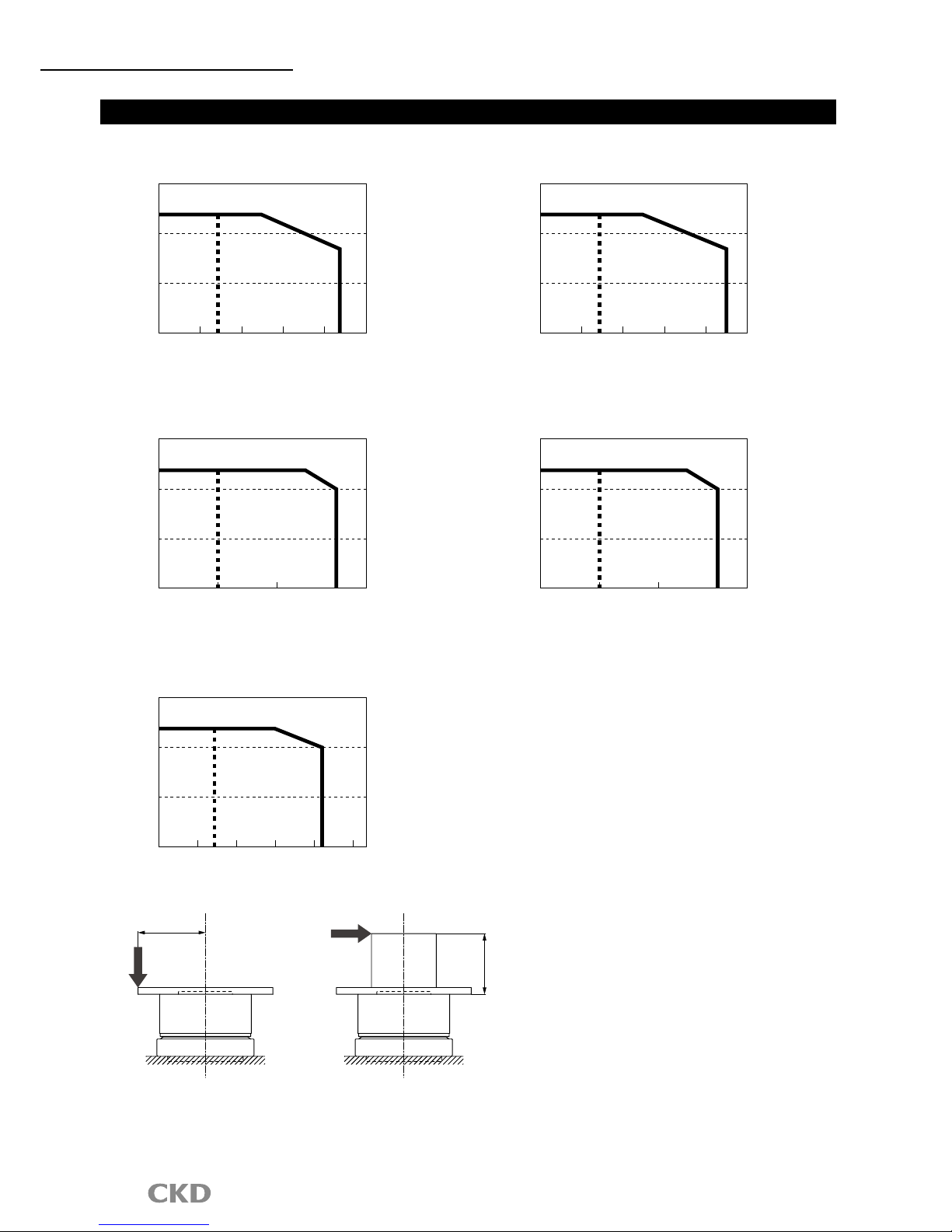
(Note) moment load
M(N㨯m)=F(N)×L(m)
M: Moment load
F: Load
L: Distance from output shaft center
M(N㨯m)=F(N)×(L+0.02)(m)
M: Moment load
F: Load
L: Distance from output shaft flange
(Fig. a) (Fig. b)
L
Speed/max. torque characteristics
AX1022TS
AX1045TS
AX1150TH
AX1210TH
ާTROި
ާ0Oި
*This graph shows the characteristics under 3 phase AC200V
Continuous
movemen
t
range
+PVGTOKVVGPV
OQXGOGPVTCPIG
ާTROި
ާ0Oި
*This graph shows the characteristics under 3 phase AC200V
Continuous
movemen
t
range
+PVGTOKVVGPV
OQXGOGPVTCPIG
ާTROި
ާ0Oި
*This graph shows the characteristics under 3 phase AC200V
Continuous
movemen
t
range
+PVGTOKVVGPV
OQXGOGPVTCPIG
ާTROި
ާ0Oި
*This graph shows the characteristics under 3 phase AC200V
Continuous
movemen
t
range
+PVGTOKVVGPV
OQXGOGPVTCPIG
ާTROި
ާ0Oި
*This graph shows the characteristics under 3 phase AC200V
Continuous
movemen
t
range
+PVGTOKVVGPV
OQXGOGPVTCPIG
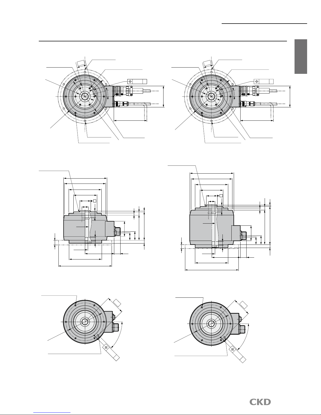
4
Dimensions
AX1000T
Series
AX1000T
Actuator
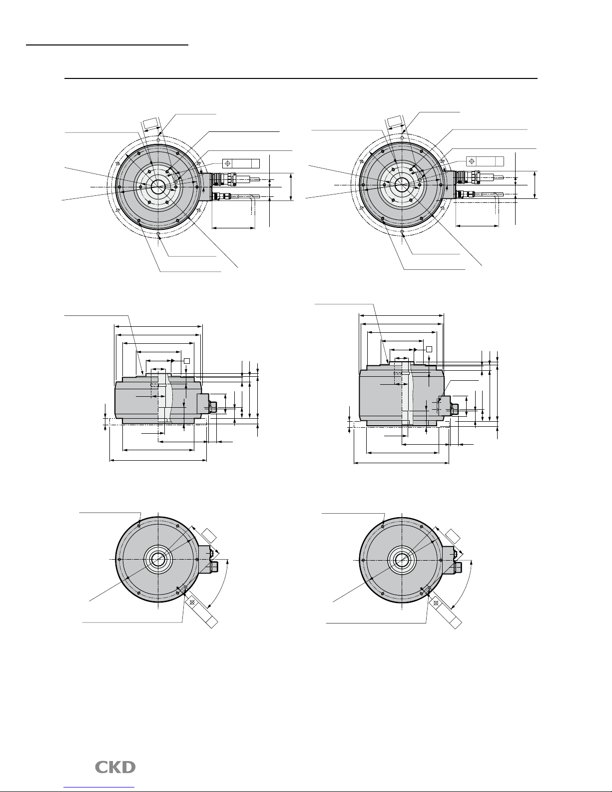
Dimensions
AX1022T
AX1045T
(Option)
For mounting dial plate
(Cable bending range)
(Including hollow section)
Rotating section
Mounting base
6-Φ7 (straight)
6-M6 depth 11 (straight)
P.
C
.D.140
P.C.D.70
6-M6 depth 9 (straight)
P.C.D.180
185
78
19.5
Rotating section
(Including hollow section)
Φ40h7
Φ25
Φ22
Φ24
Φ120h7
Φ200
A
23
22
91
103
5
12
8
11
55
5
102
22
Φ160
Φ152
Φ120
Φ85
12
(Option)
Φ6H7 depth 8
35
15°
0.04 A
45°
P.
C
.D.140
6-M6 depth 9 (straight)
Not available if the optional base is installed.
Φ6H7 depth 8 (option)
0.04
B
70
(32)
(27)
(Option)
For mounting dial plate
(Cable bending range)
(Including hollow section)
Rotating section
Mounting base
6-Φ7 (straight)
6-M6 depth 11 (straight)
P.C
.D
.140
P.C.D.70
6-M6 depth 9 (straight)
P.C.D.180
185
78
19.5
Φ160
A
Φ152
Φ120
Φ85
Φ25
Φ22
Φ24
Φ120h7
Φ200
102
22
Φ40h7
Rotating section
(Including hollow section)
23
8
126
138
55
11
12
12
22
5
5
(Option)
Φ6H7 depth 8
35
15°
0.04 A
45°
P.
C
.D.140
6-M6 depth 9 (straight)
Not available if the optional base is installed.
Φ6H7 depth 8 (option)
0.04
B
70
(32)
(27)
Note 1) The origin of the actuator may differ from the dimensions shown above.
Origin can be configured randomly using the origin offset function.
5
AX1000T
Series
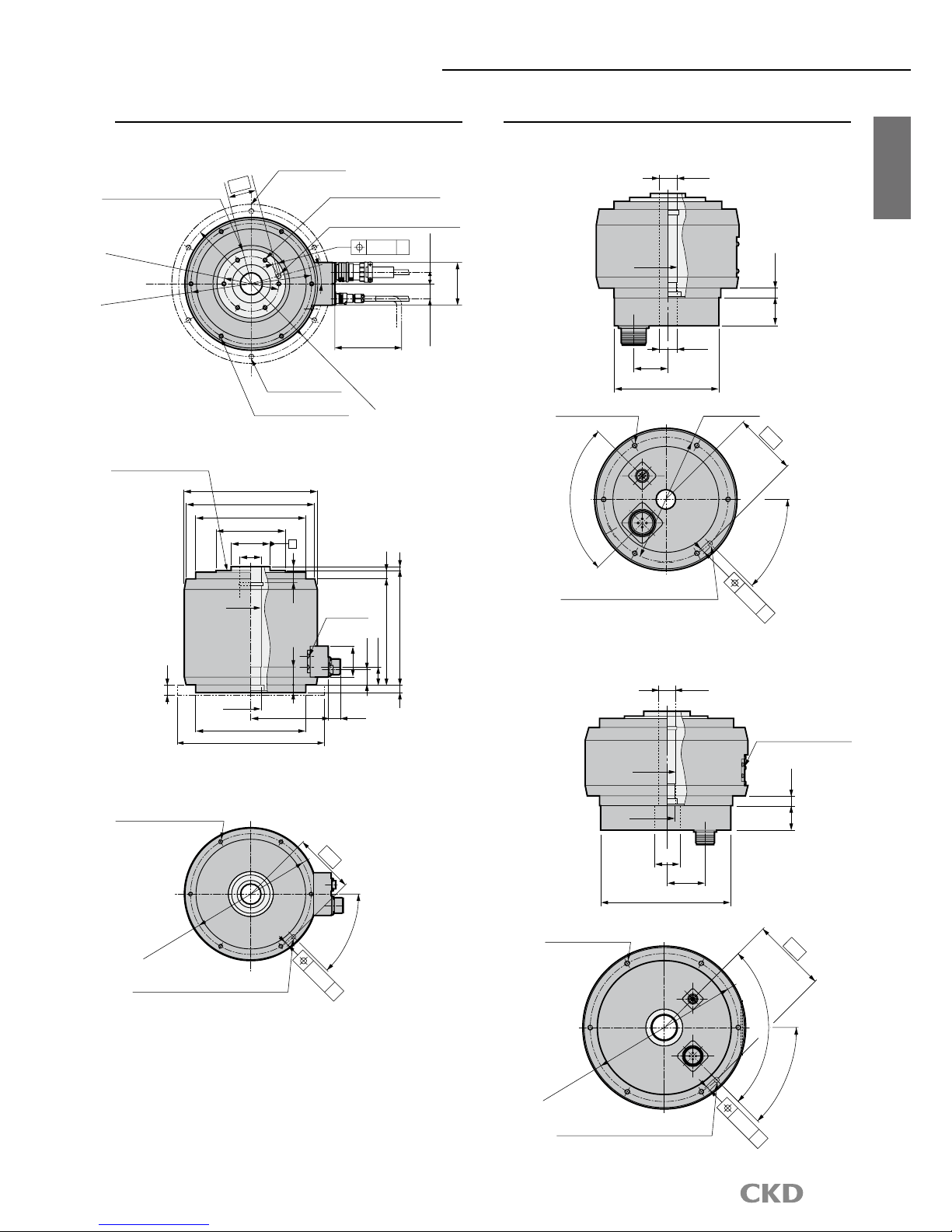
Dimensions
AX1075T
AX1150T
(Cable bending range)
For mounting dial plate
(Option)
(Including hollow section)
185
P.
C.D.265
P.
C.D.100
P.
C.D.220
Mounting base
6-M8 depth 12 (straight)
6-Φ9 (straight)
6-M8 depth 14 (straight)
78
20.7
Rotating section
Φ8H7 depth 10 (option)
50
15°
0.04 A
Rotating section
(Including hollow section)
Φ70h7
Φ40
Φ37
Φ39
Φ200h7
Φ290
A
29
37
100
115
15
12
8
14
55
8
15
146.5
22
Φ242
Φ234
Φ200
Φ125
45°
Φ8H7 depth 10 (option)
Not available if the optional base is installed.
P.
C.D.220
0.04
B
1
10
6-M8 depth 12 (straight)
17
(32)
(27)
(Cable bending range)
(For mounting dial plate)
(Option)
(Including hollow section)
185
P.
C.D.265
P.
C.D.100
P.
C.D.220
Mounting base
6-M8 depth 12 (straight)
6-Φ9 (straight)
6-M8 depth 14 (straight)
78
Rotating section
Φ8H7 depth 10 (option)
50
15°
0.04 A
15
Rotating section
(Including hollow section)
Φ70h7
Φ40
Φ37
Φ39
Φ200h7
Φ290
A
29
2-M4
GND for mounting
37
145
160
15
12
8
14
55
8
146.5
22
Φ242
Φ234
Φ200
Φ125
45°
Φ8H7 depth 10 (option)
Not available if the optional base is installed.
P.
C.D.220
0.04
B
1
10
6-M8 depth 12 (straight)
20.7
17
(32)
(27)
Note 1) The origin of the actuator may differ from the dimensions shown above.
Origin can be configured randomly using the origin offset function.
6
Standard dimensions and dimensions with options
AX1000T
Series
AX1000T
Actuator
Dimensions with options
Bottom connector (C)
AX1022T/AX1045T
Dimensions
AX1210T
AX1075T/AX1150T/AX1210T
(Cable bending range)
For mounting dial plate
(Option)
(Including hollow section)
185
P.
C.D.265
P.
C.D.100
P.
C.D.220
Mounting base
6-M8 depth 12 (straight)
6-Φ9 (straight)
6-M8 depth 14 (straight)
78
Rotating section
Rotating section
(Including hollow section)
Φ242
Φ234
Φ200
Φ125
Φ70h7
Φ40
29
15
190
37
8
55
14
15
205
8
Φ39
2-M4
GND for mounting
Φ37
Φ200h7
146.5
22
Φ290
A
45°
Φ8H7 depth 10 (option)
Not available if the optional base is installed.
P.
C.D.220
0.04
B
1
10
6-M8 depth 12 (straight)
Φ8H7 depth 10 (option)
50
15°
0.04 A
20.7
17
(32)
(27)
Φ25
Φ119
Φ22
37.5
30 (11)
90°
45°
Not available if the optional base is installed.
Φ6H7 depth 8 (option)
6-M6 depth 9 (straight)
0.04
B
70
P.C.D.140
Φ24
Φ40
Φ198
2-M4 GND for mounting
(AX1150T and AX1210T only)
60
Φ55
35 (14)
90°
P.
C.D.220
45°
Φ8H7 depth 10 (option)
Not available if the optional base is installed.
0.04
B
11
0
6-M8 depth 12 (straight)
Φ39
Φ37
Note 1) The origin of the actuator may differ from the dimensions shown above.
Origin can be configured randomly using the origin offset function.
 Loading...