

CKD ABSODEX AX9000XS-U2 Instruction Manual

SMF-2008-A
Instruction Manual
ABSODEX
AX Series
XS Type
CC-Link specification
Before using this product, be sure to
read this Instruction Manual.
In particular, read the descriptions on
safety carefully.
Store this Instruction Manual so that it
can be taken out and read quickly as
necessary.

Contents
ABSODEX
AX series [XS type CC-Link specification]
Instruction Manual No. SMF-2008-A
Introduction ··························································································· 1
1. Specifications
1.1 Product Configuration ·································································· 1-1
1.2 General Specifications of Driver ····················································· 1-2
1.3 Performance Specifications of Driver ··············································· 1-3
2. Wiring
2.1 Panel Description ········································································ 2-1
2.2 Communication Connector ···························································· 2-2
2.3 Connecting the Communication Cable ············································· 2-3
2.4 IO interface ················································································ 2-5
2.4.1 Wiring of emergency stop input (TB3) ······································· 2-5
3. CC-Link Communication Function
3.1 Communication Specifications ······················································· 3-1
3.2 I/O Devic e ·················································································· 3-2
3.3 Data Communication Timing Chart ·················································· 3-7
3.3.1 Monitor code ········································································ 3-7
3.3.2 Command code ···································································· 3-8
3.3.3 Response code ···································································· 3-9
3.4 Defining the CC-Link Register ························································ 3-10
3.5 Connection with CC-Link Unit ························································ 3-12
3.6 Monitoring t he CC-Link Communication State ··································· 3-15
3.7 LED Indication ············································································ 3-16
3.8 7-segment LED Indication ····························································· 3-17
4. Network Operation Mode
4.1 Point Table Operation ··································································· 4-1
4.1.1 Operation method ································································· 4-1
4.1.2 Point table data ···································································· 4-2
4.1.3 Point table setting example ····················································· 4-5
4.2 Data Input Operat ion ···································································· 4-8
4.2.1 Operation method ································································· 4-8
4.2.2 Input data ············································································ 4-9
4.2.3 Input data setting examples ···················································· 4-11
Created on June 1, 2016

Introduction
Introduction
Thank you for choosing our ABSODEX.
ABSODEX is a direct-drive index unit developed to drive intermittently operated turntables or the likes of
general industrial assembling machines, inspection machines, etc. flexibly at a superior preci sion.
This Instruction Manual is dedicated to the ABSODEX AX series XS type driver CC-Link specification.
It is not applied to other types.
For the operation method, precautions on operation, maintenance and inspection items and so on, refer
to "Instruction Manual for AX Series TS/TH/XS type" (SMF-2006) contained in the attached CD-ROM.
The descriptions, specifications and appearances written in this Instruction Manual may be changed
without notice in the future.
[SMF-2008-A]
– 1 –

1. Specifications
Name
Quantity
1
Driver unit
1
PC4/3-ST-7.62 (Phoenix Contact)
PC4/5-ST-7.62 (Phoenix Contact)
BLZ5.08/F AU (Weidmüller)
1. Specifications
1.1. Product Configuration
2 Accessories
CN5 motor power connector:
CN4 power supply connector:
CN3 communication connector (CC-Link):
1
1
1
[SMF-2008-A]
– 1-1 –

1.2. General Specifications of Driver
Item AX9000XS-U2 (CC-Link specification)
Single-phase or three-phase: 200V AC ± 10% to 230V AC ±
Main
Power
10% (standard)
1-100V AC - 10% to 115V AC + 10% (J1:option)
1. Specifications
Control
Frequency 50/60 Hz
Rated input current 1.8 A
Input: Phase number Single-phase or three-phase
Output voltage 0~230 V
Output frequency 0~50 Hz
Rated output current 1.9 A
Output: Phase number Three-phase
Power system TN, TT, IT
Mass About 1.6 kg
Outside diameter size W75 * H220 * D160
Configuration Open modular type (driver, and controller)
Operating Ambient
Temperature Range
1-200V AC - 10% to 230V AC + 10% (standard)
1-100V AC - 10% to 115V AC + 10% (J1:option)
0 to 50°C
Operating Relative
Humidity Range
Storage Ambient
Temperature Range
Storage Relative Humidity
Range
Atmosphere Free from corrosive gases, and dust
Anti-noise 1,000V (P-P), pulse width 1µsec, startup 1nsec
Anti-vibration 4.9m/s2
Altitude Altitude: 1,000 m or less
Protection IP2X (CN4 and CN5 are excluded)
20 to 90%RH (No condensation allowed)
-20~65ºC
20 to 90%RH (No condensation allowed)
– 1-2 –
[SMF-2008-A]

1. Specifications
Number of Controlled
Axes
Angle Setting Minimum
Unit
Maximum Instruction
Value
<Five types>
7-segment LED (2 digits)
Communication
Interface
<Input>
<Output>
64 points
Electronic Thermal
Protects the actuator from being overheated.
1.3. Performance Specifications of Driver
Item Description
1 axis, 4,194,304 pulses/rotation
Angle Setting Unit
Speed Setting Unit
Speed Setting Range
Number of Indexes
Timer
Programming Language
Programming Method
Operation Mode
Coordinate
Acceleration Curve
Status Display
° (degree), pulse, and number of indexes
0.001°, 1 pulse (= about 0.31 sec [0.000086 deg.])
sec, rpm
0.01 to 100 sec/0.11 to 240 rpm
1 to 255
8 digit input ±99,999,999
0.01 to 99.99sec
NC language
Data setting through RS-232C port using PC
Auto, single block, MDI, jog, servo OFF
Pulse string input, network operation mode
Absolute and incremental
Modified sine (MS), Modified constant velocity (MC, MC2)
Modified trapezoid (MT), Trapecloid (TR)
LED power lamp display
Motion Display
CC-Link Communication
Function
(Ver. 1.10, 2 stations
occupied, remote device
station)
Program Capacity
Meets RS-232C specification
Home positioning instruction, reset, start, stop, continuous rotation
stop, emergency stop, answer, position deviati on counter clear,
program number selection, brake release, serv o ON, program
number setting, ready return
Alarm 1 and 2, positioning completion, in-position, standby for star t
input, M code 8 points, output during indexing 1/2, ho m e posit i on
output, M code strobe, segment position strobe, servo status,
ready output
<NC program>
About 6,000 characters (256 pcs.)
<Point table>
[SMF-2008-A]
– 1-3 –

1. Specifications
--- MEMO ---
– 1-4 –
[SMF-2008-A]

2. Wiring
CN2 Encoder cable connector
Control power
LED
Main power
LED
Main
power
Control
power
Actuator output
terminal
Nameplate
Ground terminal
(2
Motion display
7
Gain 1 adjustment DIP switch
(convergence time)
Gain 2 adjustment DIP switch
(load)
CN1 RS-232C connector
TB1 Safety function
terminal
CC-Link LED
CN3 CC-Link connector
TB3 Emergency stop
terminal
TB2 Brake terminal
2. Wiring
2.1. Panel Description
A terminal strip and connectors, etc. are located on the front panel of the driver.
-segment LED (2 digits)
-M4)
Fig. 2.1 XS type CC-link specification, Driver panel
*1
Note *1: The safety function (TB1) of this product does not correspond to the accreditation of the safety
standards.
[SMF-2008-A]
– 2-1 –
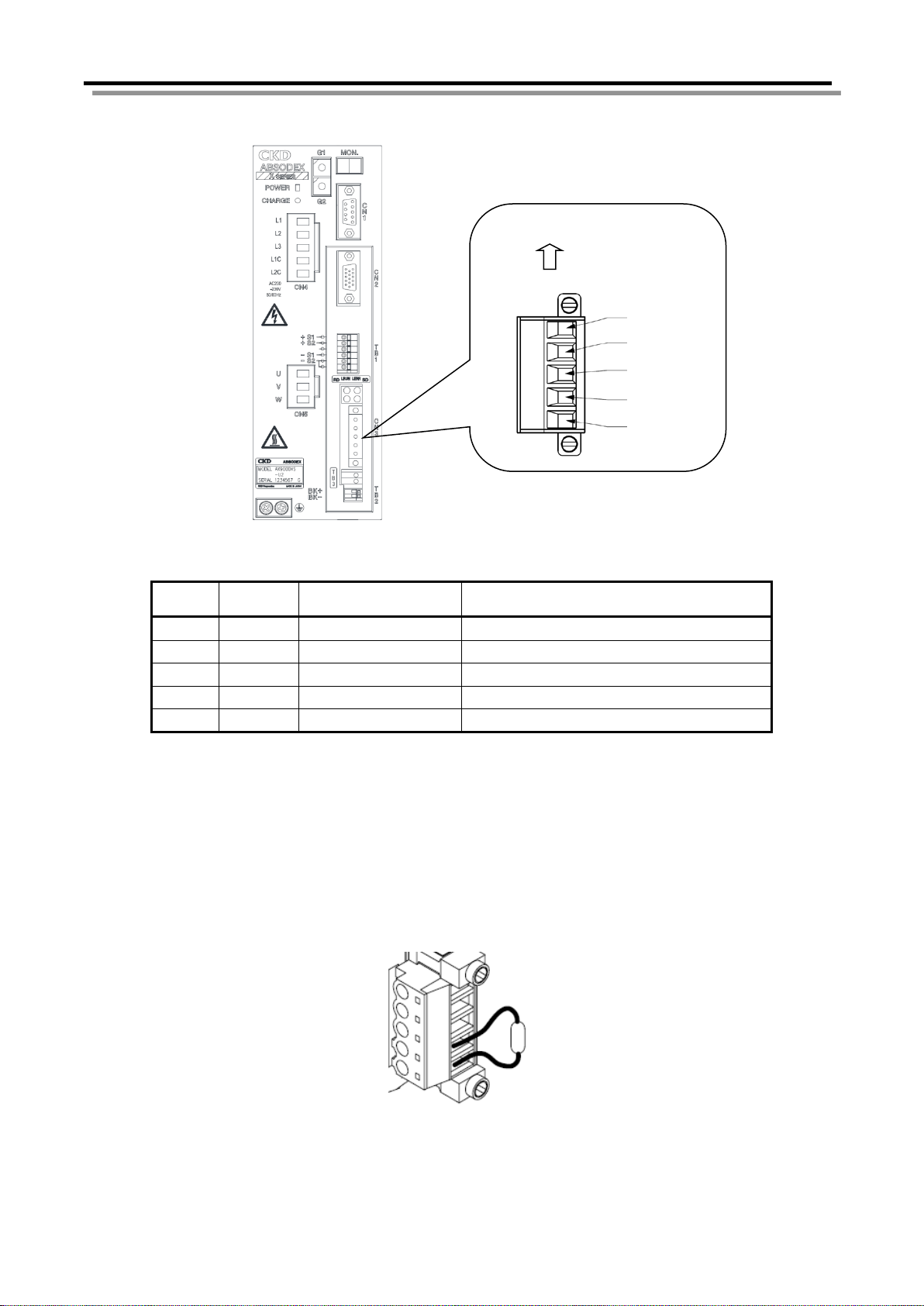
2.2. Communication Connector
Signal
name
1
DA
Data A
Connect the data A cable.
2
DB
Data B
Connect the data B cable.
3
DG
Data ground
Connect the data ground cable.
4
SLD
Shield
Connect the shielding cable. *1
5
FG
Frame ground
Connect the frame ground cable.
*1 *2
SLD (Bare)
DG (Yellow)
DB (White)
DA (Blue)
Up
FG
The pin layout of CC-Link communication connect or CN3 is shown below.
5
4
3
2
1
Fig. 2.2 Communication connector, Pin layout
Table 2.1 Pin layout of CN3
Pin
Function Description
2. Wiring
*1 The SLD and FG terminals are connected inside.
*2 Be sure to connect the grounding terminal (heat sink section) of the driver to operate.
Do not tie the frame ground cable together with the protective ground cabl e, power cable or th e
like.
(Otherwise noise will intrude, possibly making communications unstable.)
For details, refer to the CC-Link Laying Manual a nd so on.
Connect a terminator across terminals "DA" and "DB" i f the module is connected at the end of the
network.
Fig. 2.3 Terminator, Connection example
[SMF-2008-A]
– 2-2 –

2. Wiring
If solderless terminals are not used
Cable
Insulating tube
If solderless terminals are used
Cable
Cable
To insert two cables
Wire 0.5mm2
(Do
Wire 0.5mm2
(Do not twist)
Solderless terminal
Special tool for solderless terminal
Solderless terminal
Special tool for solderless terminal
Previous station
(Blue)
(Blue)
(White)
(Yellow)
(Bare)
Next station
2.3. Connecting the Communication Cable
Follow the procedure below to connect the spec i al CC-Link cable to the module.
(1) Peel the sheath of the cable off without causing a broken wire (length of peeled cable sheath:
7mm). Do not solder the bare cable. Otherwise poor continuity may be caused. The solderless
terminals specified below are recommended. Note that the peeling size of the cable sheath
varies according to the type of the solderless terminal (see the figures below).
About 50mm
To insert a single cable
Part name: Sleeve with
insulating cover
Model: H0.5/12
Manufacturer: Nihon
Weidmüller
not twist)
Part name: Crimper
Model: PZ1.5 or PZ4
Manufacturer: Nihon Weidmüller
Part name: Sleeve with
insulating cover
Model: H0.5/15
Manufacturer: Nihon
Weidmüller
Fig. 2.4 Peeling size of communication cable
Part name: Crimper
Model: PZ1.5 or PZ4
Manufacturer: Nihon Weidmüller
(2) Insert the DA (blue), DB (white), DG (yellow) and SLD (bare) cables of the CC-Link cable into
the corresponding holes while taking care of the orientation of the accessory connection
connector (BLZ5.08/5FAU) (see the figure below), and tighten the cable fixing screw.
The recommended connector is BLZ5.08/FAU manufactured by Weidmüller.
(White)
(Yellow)
(Bare)
Fig. 2.5 Connection example of communication cable
(3) After checking that the cable name is the same as the one indicated on the module, i nsert the
connection connector into the module and securely tighten the connector fixing screw to a
tightening torque of 0.3N·m.
[SMF-2008-A]
– 2-3 –

CAUTION
Be sure to use special signal cables complying with the CC-Link specifications.
Before inserting the cable into the connector, loosen the cable fixing screw sufficiently
to avoid the cable entering the back side of the connector instead of the connector
tightening side.
For the shield wires for CC-Link special cables, connect to “SLD” of each unit via “FG”
and ground with class D (level III grounding resistance of 100 Ω or lower) SLD and
FG are connected inside the unit.
For those provided with a connector fixing screw, securely tighten the connector fixing
screw when inserting the connector. Otherwise the connector may be dislocated and
cause malfunction. For those not provided with a connector fixing screw, check that the
catch of the connector snaps in position.
Loosen the two fixing screws before removing the connector. The connector may be
damaged if excess force is applied to the connector without the two screws loosened.
Do not bend the communication cable forcibly. Assure a sufficient bending radius.
Remove the connector vertically to avoid excess force from being applied to the
connector.
Reserve a sufficient distance between the communication cable and power cable
(motor cable).
If the communication cable is routed near the power cable or if they are tied, noise will
enter to make communication unstable, possibly causing frequent communication
errors and/or communication retries.
2. Wiring
For details of the laying of the communication cable, refer to the CC-Link Laying Manual, etc.
[SMF-2008-A]
– 2-4 –

2. Wiring
External power supply
* The polarity of the
CN3: emergency stop
TB3:emergency stop
Serial communication
Input processing
Emergency stop
2.4. IO interface
Connect "emergency stop input (TB3)" in the following way.
2.4.1. Wiring of emergency stop input (TB3)
24V DC
(Prepared by customer)
Rated voltage 24V ±10%, rated current withi n 5m A
external power supply
can be inverse.
Fig. 2.6 Connection example of emergency stop input (TB3)
The emergency stop input will be effective as default setting. Refer to the “AX Series TS, TH,
XS Type manual” (SMF-2006) for sett i ng instructions.
Emergency stop is a “b” contact input. Thus it will take effect when emergency stop input (TB3)
becomes open. (Emergency stop using CC-Link wi ll be effective when the input data is OFF)
Input (serial)
input (I/O)
processing
Emergency stops if either
input becomes open (or
off).
Fig. 2.7 Specification of emergency stop input
Emergency stop can be inputted by TB3’s input termin al or CN3’s DeviceNet communications and
if one of the inputs becomes open (or off), it will be recognized as emergency stop.
→ Input to TB3 is necessary to release the emergency stop.
[SMF-2008-A]
AWG20 to 24 (single cable)
AWG20 to 22 (stranded cable)
8~9mm
Fig. 2.8 Applicable cable to TB3 and peeling size
The cable sheath peeling length should be 8 or 9mm.
The applicable cable is AWG20 to 24 (single cable) or AWG20 to 22 (stranded cable).
– 2-5 –

2. Wiring
--- MEMO ---
– 2-6 –
[SMF-2008-A]
 Loading...