


CCM04 MKII
The CCM04 without card guidance is
used where space is at a premium and
the card guidance can be built around
the connector (rather than provided by
the connector itself).
The CCM04 low profile without card
guidance is dedicated to applications
where the overall height of the
connector is paramount. A range of low
profile CCM04 connectors are available
with 1.25 mm thick moldings.
The wide choice of contact configurations and molding heights suit a broad
range of applications.
Features
• Available in two molding heights 1,25
mm and 2,75 mm.
• The integrated card detection switch
(optional) is sealed against dust and grit.
• By using an inlay finish in the contact
area, the life of the precious metal is
extended by more than 10 times that
of standard gold plating.
• The height of the contact above the
insulator is 0,75 mm, allowing a wider
tolerance for the card entry slot.
• The contact area is spooned to
reduce the risk of accidental (or
deliberate) damage and to optimize
the electrical connection with the car
• The tip of the contact is protected by
the molding so that it cannot catch on
the card as the card is being inserted.
• The contact design ensur
es a
consistent and reliable contact force
over the life of the connector.
• Robustly formed printed circuit tails
e well protected by the insulator
ar
.
body
• The moldings are made from high
temperature thermoplastic suited for
infrared and convection soldering
processes.
• With tape and reel packaging as
standard, the connectors are designed
to be automatically picked & placed.
Construction
Contacts Copper alloy
Plating Contact area : Gold alloy inlay
Moldings High temp. thermoplastic UL 94V-0 rated
Mechanical Data
Number of Contacts 6, 8
Mechanical life 50,000 cycles min
Contact force 0.25 N min / 0.5 N max
Card detection switch 0.8 N max for actuation (end travel switch
actuation force actuates when card is 0,9 mm from
Vibration Frequency 10 to 500 Hz. Acceleration
2
50m/s
Shock Peak value 500 m/s
Contact Electrical Data
Insulation resistance 1,000 MΩ min
Resistance 100 mΩ max
Current rating 10 µA min / 1 A max
Dielectric strength 750 Vrms min
Switch Electrical Data
Card detection switch Normally open (closes on card insertion)
Contact resistance 100mΩ max
Dielectric strength 250 Vrms min
Current rating 1 mA min/ 10 mA max
Maximum power 0.2 VA
d.
Environmental Data
Operating temperatur
Soldering temperatur
Damp heat
Salt mist IEC 512 test number 11f (96 hours)
Card detection switch Sealed IP 54 For CCM04 1889
Ordering Code
Part Number Number of Contacts Card Presence Quantity per Reel
CCM04-1801 6 No 1800
CCM04-1814
CCM04-1889 8 Yes 1000
Packaging
e -40°C to +85°C
e Temperature/time profile acc. to CECC00802
8
Terminals : Tin lead (2µ min)
card stop) 1.8 N max for complete
depression
Duration 6 hours - amplitude 0,35 mm
Max electrical discontinuity 1µs
3 shocks in each direction of each axis
Max electrical discontinuity 1 µs
para. 6.1, Fig. 3 with peak temperature 250°C
IEC 512 test number 11c (10 days)
Sealed against dust for other versions
Switch
No
2
– Duration 11 ms
1300
5 r
eels per box.
22
Specifications and dimensions subject to change
Dimensions are shown in mm
.ck-components.com
www
Dimensional Drawings
(REF.)
25,5
0,1
0
-0,1
0,8
(REF.)
2,54 2,54 2,54
(REF.)
1,78
1
0,3
A
1,25
±0,05
0,75
25,5
±
0,2
0,25
±0,05
3,81 3,81
2,542,542,54
R
0,1
30
˚0'
Mated condition
8x
SEE DETAIL A
XX-XXX
Date Code area
Pick and plac
e area
ø
3,5
DETAIL A
2,5
25,5
5,55,5
3,81 3,81
1,8
7,79
1,5
23,2
1,5
2,542,54
1,3
0,2
2,54
(Component side)
Contact location according to
ISO 7816-2
& ENV 1375-1
& GSM11-11
C5
C1
C6
C2
C7
C3
Contact foot area
0,8 x 1
Prohibited area
8x
C8
C4
Plastic outline
Pad
0,9±0,25
0,75
16,2
0,95±0,2
5,9
0,75
+0,10
-0,05
15,45
11,8
11,18
A
23,6
25,5
±0,2
4,4
±0,2
10,9
0,25
±0,05
1,25
±0,05
30˚0'
3,81 3,81
(REF.)
25,5
0,85
0,85
0,8
(REF.)
4,4
0
-0,1
DETAIL A
Mated condition
SEE DETAIL A
XX-XXX
Card stop
Date Code area
Pick and place area
ø 3,5
SEE DETAIL
B
5,5
2,5
5,5
1,8
4,4
25,5
7,99
5,59
1,3
0,2
23,2
1,51,5
4,4
1,5
3,81 3,81
1,27
5x
2,54
Contact location according to
ISO 7816-2
Contact foot area
0,8 x 1
(Component side)
10x
C1
C5
C2
C6
C3
C7
C4
C8
SW
SW
Prohibited area
Pad
Plastic outline
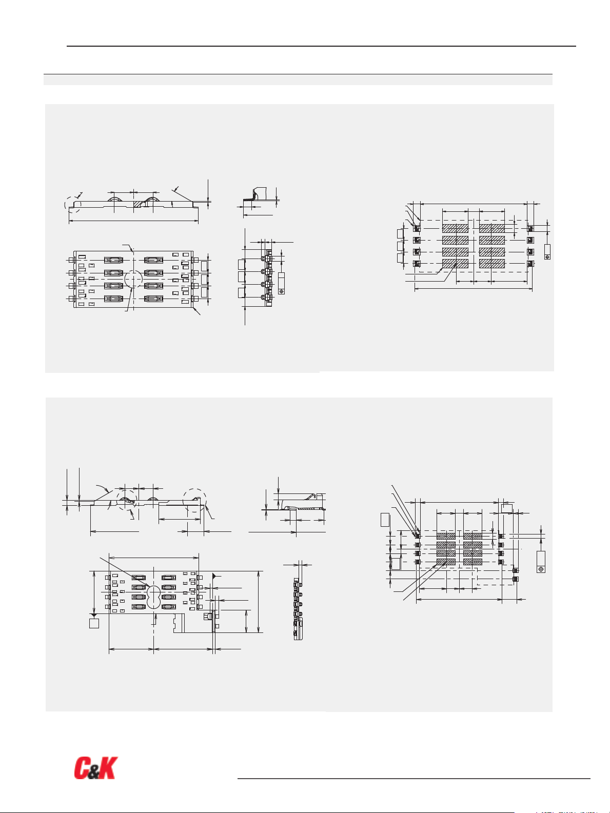
CCM04 MK II
CCM04-1814 2 x 4 contacts
CCM04-1814 PCB layout
CCM04-1889 2 x 4 contacts + switch CCM04-1889 PCB Layout
Unless otherwise stated, tolerances ar
23
0,10 mm
±
e
Specifications and dimensions subject to change
Dimensions are shown in mm
.ck-components.com
www
 Loading...