

CJB CJ ISA-E5 User Manual

CJ ISA-E5
SINGLE BOARD COMPUTER
User`s Manual
Version 1.0
CJB Computer Job S.r.l.
www.cjb.it ~ sales@cjb.it

Copyright Notice
This publication is protected by copyright and all rights are reserved. No
part of it may be reproduced or transmitted by any means or in any form,
without prior consent of the original manufacturer.
The information in this document has been carefully checked and is
believed to be accurate. However, the original manufacturer assumes no
responsibility for any inaccuracies that may appear in this manual. In no
event will the original manufacturer be liable for direct, in direct, speci al,
exemplary, incidental, incidental or consequential damages resulting
from any defect or omission in this manual, even if advised of possibility
of such damages. The material contained herein is for informational
purposes only.
Acknowledgments
Award is a registered trademark of Award Software International, Inc.
IBM, PS/2 are trademarks of International Business Machines
Corporation.
Intel, Pentium4 are registered trademarks of Intel Corporation.
Microsoft Windows is a registered trademark of Microsoft Corporation.
All other product names or trademarks are properties of their respective
owners.
ii
ISA-E5 User`s Manual

Contents
Contents
Introduction.........................................................1
Chapter 1 Features & Specifications................2
Features ...............................................................................3
Specifications.......................................................................4
Chapter 2 Jumper setting & Connectors..........9
Jumpers on the ISA-E5....................................................10
Jumper Locations on the ISA-E5........................................11
JP1, JP2: COM Power Selection ........................................12
JP3: Clear CMOS RAM Data.............................................12
JP4: LCD PANEL Power Selection ...................................12
JP5: CF Card Mode Selection ............................................13
COM2MODE1: RS232/RS422/RS485 Protocol Selection13
PWRMODE: AT Mode Selection......................................14
Connectors on the ISA-E5 ...............................................15
Connector Locations on the ISA-E5...................................16
Front Panel Connector.....................................................17
BACKLIGHT Connector ...................................................18
IrDA Connector..................................................................19
SATA1, SATA2 Connectors..............................................19
EIDE Connectors................................................................20
COM1 Serial Port...............................................................22
COM2 Serial Port...............................................................22
COM3, COM4 Serial Ports ................................................23
USB12, USB34 Connectors ...............................................23
Floppy Drive Connector.....................................................24
Parallel Port Connector.......................................................25
PS/2 Keyboard & Mouse Connector..................................26
VGA Connector..................................................................26
INT_VGA Connector.........................................................27
INT_KBMS Connector ......................................................27
AUDIO Connector..............................................................27
CPU FAN Power Connector...............................................28
System FAN Power Connector...........................................28
ATX Power Connector.......................................................28
ISA-E5 User`s Manual
iii

Contents
PWR_IN1 Connector.........................................................30
PWR_IN2 Connector.........................................................30
LAN- RJ45 Connector .......................................................31
LAN RJ45 LED..................................................................31
LVDS LCD Connector.......................................................32
CF-II Connector.................................................................33
Chapter 3 BIOS Setup.....................................34
BIOS Introduction............................................................35
Starting Setup..................................................................... 35
Using Setup........................................................................36
Getting Help.......................................................................37
In Case of Problems...........................................................37
Main Menu........................................................................38
Standard CMOS Features........................................................... 38
Advanced BIOS Features ............................................................38
Advanced Chipset Features......................................................... 39
Integrated Peripherals ................................................................39
Power Management Setup...........................................................39
PnP / PCI Configurations ...........................................................39
PC Health Status.........................................................................39
Frequency/Voltage Control................... ......................................39
Load Fail-Safe Defaults ..............................................................39
Load Optimized Defaults.............................................................39
Supervisor / User Password........................................................39
Save & Exit Setup............................. ...........................................39
Exit Without Save........................................................................39
Standard CMOS Setup....................................................40
Channel 0 HDDs / Channel 1 HDDs........................................42
Channel 2 HDDs / Channel 3 HDDs........................................44
Drive A / Drive B...............................................................46
Video..................................................................................46
Halt On...............................................................................46
Advanced BIOS Features ................................................47
CPU Feature.....................................................................48
Delay Prior to Thermal.......................................................48
Thermal Management ........................................................48
TM2 Bus Ratio...................................................................48
TM2 Bus VID ....................................................................49
Hard Disk Boot Priority ..................................................49
Bootable ADD-in Cards.....................................................49
Virus Warning....................................................................49
iv ISA-E5 User`s Manual

Contents
CPU L1 & L2 Cache ..........................................................50
CPU L2 Cache ECC Checking...........................................50
Quick Power On Self Test..................................................50
First/Second/Third/Other Boot Device...............................50
Swap Floppy Drive.............................................................50
Boot Up Floppy Seek .........................................................50
Boot Up NumLock Status ..................................................51
Typematic Rate Setting ......................................................51
Typematic Rate (Chars/Sec)...............................................51
Typematic Delay (Msec)....................................................51
Security Option...................................................................51
MPS Version Control For OS.............................................52
OS Select For DRAM > 64MB..........................................52
Video BIOS Shadow ..........................................................52
Small Logo (EPA) Show....................................................52
Advanced Chipset Features.............................................53
DRAM Settings..................................................................53
DRAM Clock/Drive Control............................................54
Current FSB Frequency......................................................54
Current DRAM Frequency.................................................54
DRAM Clock......................................................................54
DRAM Timing ...................................................................54
SDRAM CAS Latency [DDR/DDR2]................................54
Bank Interleave...................................................................54
Precharge to Active(Trp)....................................................55
Active to Precharge(Tras)...................................................55
Active to CMD(Trcd).........................................................55
REF to ACT/REF (Trfc)....................................................55
ACT(0) to ACT(1) (TRRD) ..............................................55
AGP & P2P Bridge Control.............................................55
AGP Aperture Size.............................................................56
VGA Share Memory Size...................................................56
Direct Frame Buffer ...........................................................56
Select Display Device.........................................................56
Panel Type..........................................................................56
CPU & PCI Bus Control..................................................56
PCI Master 0 WS Write......................................................57
PCI Delay Transaction .......................................................57
Memory Hole......................................................................57
System BIOS Cacheable.....................................................57
Video RAM Cacheable.......................................................57
ISA-E5 User`s Manual
v

Contents
Init Display First ................................................................57
Integrated Peripherals.....................................................58
VIA OnChip IDE Device .................................................58
OnChip SATA....................................................................59
SATA Mode.......................................................................59
IDE DMA transfer access ..................................................59
OnChip IDE Channel0.......................................................59
OnChip IDE Channel1.......................................................59
IDE Prefetch Mode ............................................................59
Primary/Secondary Master/Slave PIO ...............................59
Primary/Secondary Master/Slave UDMA..........................59
IDE HDD Block Mode.......................................................59
VIA OnChip PCI Device .................................................60
AC97 Audio.......................................................................60
VIA VT6103 LAN.............................................................60
OnChip USB Controller.....................................................60
OnChip EHCI Controller ...................................................60
USB Emulation ..................................................................60
USB Keyboard Support......................................................61
USB Mouse Support ..........................................................61
SuperIO Device.................................................................61
Onboard FDC Controller....................................................61
Onboard Serial Port 1/Port 2..............................................61
UART Mode Select............................................................61
RxD, TxD Active...............................................................62
IR Transmission Delay.......................................................62
UR2 Duplex Mode.............................................................62
Onboard Parallel Port.........................................................62
Parallel Port Mode..............................................................62
EPP Mode Select................................................................62
ECP Mode Use DMA.........................................................62
PWRON After PWR-Fail...................................................62
Onboard Serial Port 3/Port 4/Port 5/Port 6.........................62
Serial Port 3/Port 4/Port 5/Port 6 Use IRQ ........................62
Watch Dog Timer Select....................................................62
Power Management Setup...............................................63
ACPI Function ...................................................................63
Power Management Option................................................64
HDD Power Down.............................................................64
Suspend Mode....................................................................64
Video Off Option ...............................................................64
vi ISA-E5 User`s Manual

Contents
Video Off Method ..............................................................65
MODEM Use IRQ.............................................................. 65
Soft-Off by PWRBTN........................................................65
IRQ/Event Activity Detect...............................................65
PS2KB Wakeup from S3/S4/S5.........................................66
PS2MS Wakeup from S3/S4/S5.........................................66
USB Resume from S3 ........................................................66
VGA ...................................................................................66
LPT & COM.......................................................................66
HDD & FDD ......................................................................66
PCI Master..........................................................................66
PowerOn by PCI Card........................................................66
Modem Ring Resume.........................................................66
RTC Alarm Resume ...........................................................66
Date (of Month)..................................................................66
Resume Time (hh:mm:ss)...................................................67
IRQs Activity Monitoring................................................67
Primary INTR.....................................................................67
IRQ3 (COM 2) .................................................................67
IRQ4 (COM 1) .................................................................67
IRQ5 (LPT 2) ...................................................................67
IRQ6 (Floppy Disk)...........................................................68
IRQ7 (LPT 1) ...................................................................68
IRQ8 (RTC Alarm)............................................................68
IRQ9 (IRQ2 Redir)............................................................68
IRQ10 (Reserved)..............................................................68
IRQ11 (Reserved)..............................................................68
IRQ12 (PS/2 Mouse).........................................................68
IRQ13 (Coprocessor).........................................................68
IRQ14 (Hard Disk)............................................................68
IRQ15 (Reserved)..............................................................68
PnP/PCI Configuration Setup.........................................69
PNP OS Installed................................................................69
Reset Configuration Data...................................................69
Resources Controlled By....................................................70
IRQ Resources..................................................................70
IRQ-3/IRQ-4/IRQ-5/IRQ-7/IRQ-9/IRQ-10/IRQ-11/IRQ-12
/IRQ-14/IRQ-15 assigned to...............................................71
DMA Resources................................................................71
DMA-0/ DMA-1/ DMA-3/ DMA-5/DMA-6/ DMA-7
assigned to..........................................................................71
ISA-E5 User`s Manual
vii

Contents
PCI/VGA Palette Snoop.....................................................72
Assign IRQ For VGA.........................................................72
Assign IRQ For USB .........................................................72
PC Health Status ..............................................................73
CPU Warning Temperature................................................73
Current System Temp. .......................................................73
Current CPUDEI Temperature . ..........................................73
Current CPU Temperature .................................................73
Current CPUFAN Speed....................................................74
Current SYSFAN Speed ....................................................74
Vcore/1.5V/3.3V/5V/12V/-12V/VBAT/5VSB Voltages...74
Shutdown Temperature......................................................74
CPU Fan Control ................................................................74
SYSTEM Fan Control........................................................74
Frequency/Voltage Control.............................................75
CPU Clock Ratio................................................................75
Auto Detect PCI Clk ..........................................................75
Spread Spectrum ................................................................75
Load Fail-Safe Defaults ...................................................76
Load Optimized Defaults.................................................76
Supervisor/User Password Setting..................................77
Exit Selecting ....................................................................78
Save & Exit Setup.............................................................78
Exit Without Saving...........................................................78
CHAPTER 4 Appendix....................................79
A. I/O Port Address Map.................................................80
B. Interrupt Request Lines (IRQ)...................................81
C. POST Beep...................................................................82
viii ISA-E5 User`s Manual

Introduction
This manual is designed to give you information on the ISA-E5
Single Board Computer card. The topics covered in this manual
are as follows:
Features
Specification
Jumper setting and Connectors
BIOS Setup
Appendix
ISA-E5 User`s Manual
1

Chapter 1
Features & Specifications
Features .....................................................................3
Specifications............................................................4
2 ISA-E5 User`s Manual

Features
• Support both VIA C7 and EDEN NanoBGA2 CPU in V4 bus for
either High performance or Low Power.
•
Compact design with Rich I/O functions for Panel PC, Thin-client
terminal, Automation.
• Multiple I/O support, up to four USB2.0 ports and four COM ports.
COM1, COM2 can be powered by either 5V or 12V.
•
Support LVDS LCD up to dual 24-bits channel. The resolution
can be up to 1600x1200. Dual Independent display and rotation
supported by Drivers.
• Dedicated LCD inverter connector with LCD Brightness control
by software. Software ready for Windows XP/2K.
•
Single 10/100M LAN Design with Remote Boot and Wake Up on
LAN support.
• AC97 3D Audio Codec on board with internal connection for
Line-OUT, Line-IN and Microphone.
•
Support versatile storage devices: 3.5”HDD, 2.5”HDD, DOM
module in 40pins and 44pins.
•
COM2 supports RS232/422/485, selectable by jumpers.
•
Dual SATA-I ports, support IDE mode, RAID0 and RAID1.
•
Half-Size ISA Bus CPU card, while with Power connector and
four screw holes for standalone operation.
• Bundle Low noise CPU cooler for C7 1.5GHz or higher speed
CPU. FANLESS CPU heat sink available for EDEN 1.0GHz or
lower speed CPU.
•
PC104-ISA socket and four mounting holes for Standard PC104
module support.
• One Compact Flash Socket for CF Flash Card support.
ISA-E5 User`s Manual
3

Specifications
•
Processor Support:
VIA nanoBGA2 V4 interface CPU mounted on board.
Support VIA C7 High performance CPU 1.5G, 1.6G, 1.8G
and 2.0GHz.
Support VIA EDEN (V4) Low Power CPU 400M, 500M,
600M, 800M, 1.0G, 1.2G, 1.5GHz.
•
Major Chipset:
VIA CN700 and VT8237RPlus chipset.
VIA VT6103L LAN chip.
Winbond 83627HF Super I/O.
ALC655 AC97 Audio chip.
•
System Memory:
One DDR DIMM 184-pins Socket support DDR 266/333/400
unregistered non-ECC up to 1.0 GB.
• Video Controller:
CN700 Integrated S3 Graphic Engine.
One 15-Pins D-Sub Female connector on external I/O ports
for CRT Displays.
One 40-pins connector for Dual 18/24-bits LVDS LCD
displays.
One 5-pins JST connector for Inverter power and brightness
control.
•
Super I/O:
Winbond 83627HF LPC I/F Super I /O chip.
Four COM ports: One D-Sub connector on external I/O ports
and three in 2x5 box-header, support standard RS-232
protocols. Dual COM ports or single COM port cable with
mounting bracket enclosed for external COM ports access.
COM1 and COM2 Pin9 are powered with either 5V or 12V or
Ring-In selected by Jumpers.
COM2 are RS232/422/485 selectable by jumpers.
1 x Parallel port supports SPP/ECP/EPP mode.
1 x IrDA port.
1x standard 34-pins FDD connector.
Four USB2.0 ports with 2x5 box-header. Dual USB ports
cable with mounting bracket enclosed for external USB
4 ISA-E5 User`s Manual

devices.
1 x PS2 Keyboard/mouse connector with Mini-DIN 6-pins on
external I/O ports. Y-cable enclosed for both Keyboard and
Mouse access.
• Hardware Monitor:
83627HF integrated hardware monitor chip to monitor
Voltages, Temperatures and FAN speed.
Temperature Monitor: CPU thermal diode, one sensor close
to CPU socket, one sensor close to 83627HF chip.
One CPU FAN for CPU cooler and one SYS FAN for chassis
FAN. All FAN speed are monitored and can be controlled by
CPU and System temperature to turn-on or turn-off.
•
10/100M Ethernet:
One VIA VT6103L on board for 10/100M LAN.
Support Wake Up-on-LAN.
The LAN connector is RJ45 connector on external I/O ports.
RJ45 connector with Link, Activity and Speed LED
indicators.
Remote Boot Agent is supported with PXE and RPL prot ocol.
•
PIDE and SATA:
PIDE controller build in VT8237 support up to UltraDMA
mode 6 or ATA133 speed.
One standard 40-pins box header to support 3.5” HDD,
CDROM, DVD player or DOM Flash Disk.
One standard 44-pins box-header support 2.5” HDD, Slim
CD-ROM or DOM Flash Disk.
One Compact Flash-II socket share with Secondary IDE
Channel. Jumper selectable as Master or Slave device.
Two SATA connectors from VT8237R support SATA-I and
SATA-II devices. Two SATA HDDs can be configured as
RAID0 or RAID1 through Option- RO M or Windows
Utilities.
•
Watchdog Timer:
The disable/enable selection can be programmed in BIOS
setup. The timeout interval can be set up through
programmed I/O address 300h/301h.
The timeout event will generate the RESET.
•
CMOS:
On-board RTC with 242 bytes of Battery-back CMOS RAM.
One 3-pins Jumper/2mm to clear CMOS data.
ISA-E5 User`s Manual
5

•
Audio:
RealTek ALC655 AC97 Audio chip on-board.
One 10-pins pin-header to provide internal audio device
connection.
Support Line-Out, Line-In and Microphone.
• BIOS:
Award Standard PnP Flash BIOS 6.0.
4Mbit FlashROM with BootBlock for Fail-safe.
BIOS utility for field update.
VBIOS for LCD panel support and LAN remote BootROM
integrated.
•
Power Connector:
Support both AT mode or ATX mode operation.
One 4-pins connector to supports ATX 5VSB power and
ATX ON/OFF control signals.
Supply +5V and +12V output power with 4-pins 3.5” FDD
type 4-pins power connector.
Support standalone operation with Standard 3.5” HDD type
4-pins power connector.
•
Software Compatibility:
Microsoft windows: NT4.0, Win XP, Win 2K Prof, Win2K
Server, Win2003, .NET.
Linux RedHat 7.2, 7.3, 8.0, 9.0.
DOS 6.0 and 6.22.
QNX v6.2, WinCE 5.0.
• Cooling:
Two cooling FAN connectors close to CPU for CPU cooler
and System FAN.
Flat Heat- s ink on top of CN700 and VT8237R chipset.
Customized Cooler for VIA nanoBGA2 CPU.
FANLESS CPU heat sink available for EDEN 1.0GHz or
lower speed CPU.
Low noise CPU cooler for C7 1.5GHz or higher speed CPU.
•
Others:
One Buzzer (9mm) on-board for beep message.
•
Operating Temperature:
0~50°C Operation Rage.
Relative Humility: 5~95%, non-condensing.
6 ISA-E5 User`s Manual

•
Dimensions:
185mm(W) x 127mm(L)
4 screw holes on four corners.
ISA-E5 User`s Manual
7

This page is intentionally left blank.
8 ISA-E5 User`s Manual

Chapter 2
Jumper setting & Connectors
Jumpers on the ISA-E5...........................................10
Connectors on the ISA-E5......................................15
ISA-E5 User`s Manual
9

Jumpers on the ISA-E5
The jumpers on the ISA-E5 allow you to configure your Single Board
Computer card according to the needs of your applications. If you have
doubts about the best jumper configuration for your needs, contact your
dealer or sales representative. The following table lists the jumpers on
ISA-E5 and their respective functions.
Jumper Locations on the ISA-E5...................................... 11
JP1, JP2: COM Power Selection........................................12
JP3: Clear CMOS RAM Data............................................12
JP4: LCD PANEL Power Selection...................................12
JP5: CF Card Mode Selection............................................13
COM2MODE1: RS232/RS422/RS485 Protocal Selection13
PWRMODE: AT Mode Selection......................................14
10
ISA-E5 User`s Manual
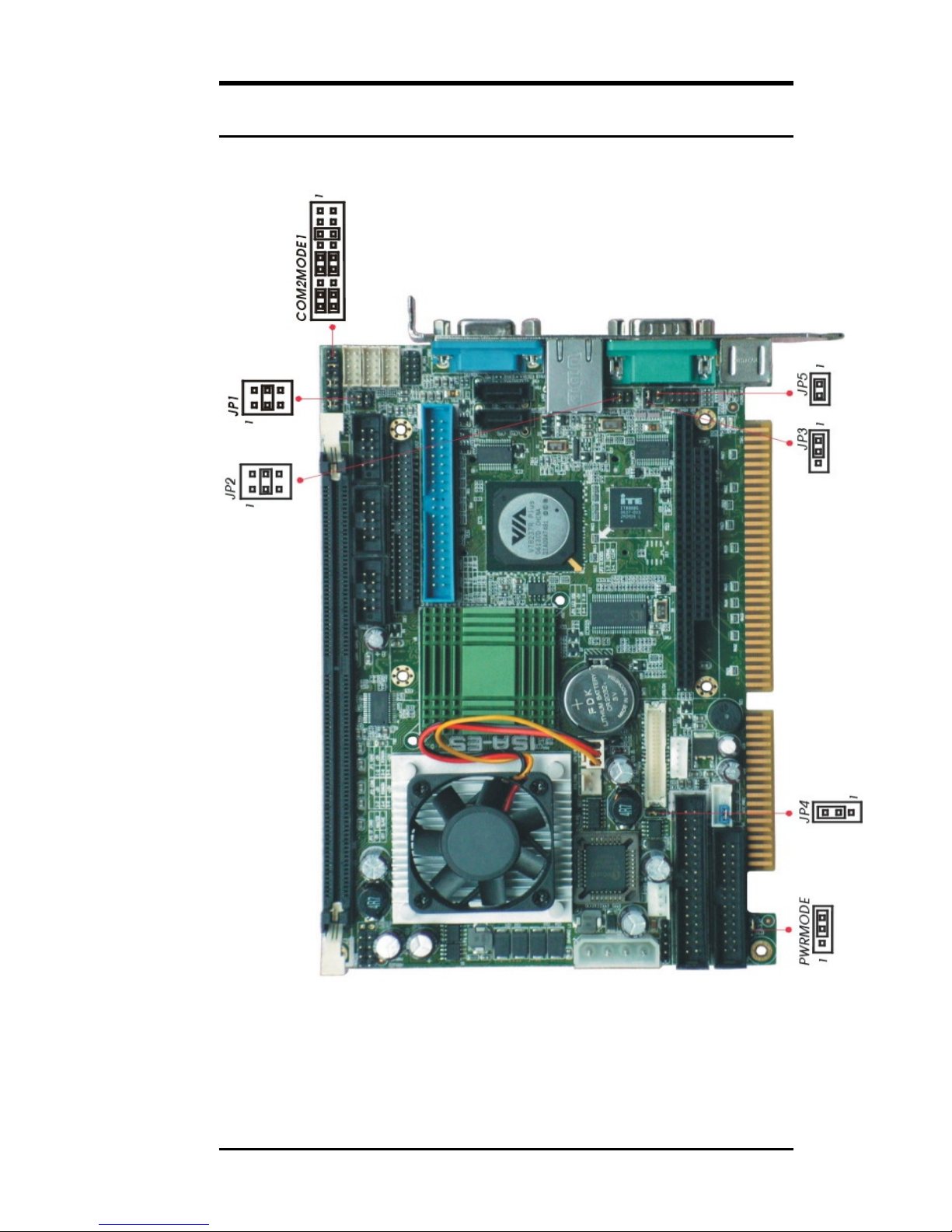
Jumper Locations on the ISA-E5
ISA-E5 User`s Manual
11
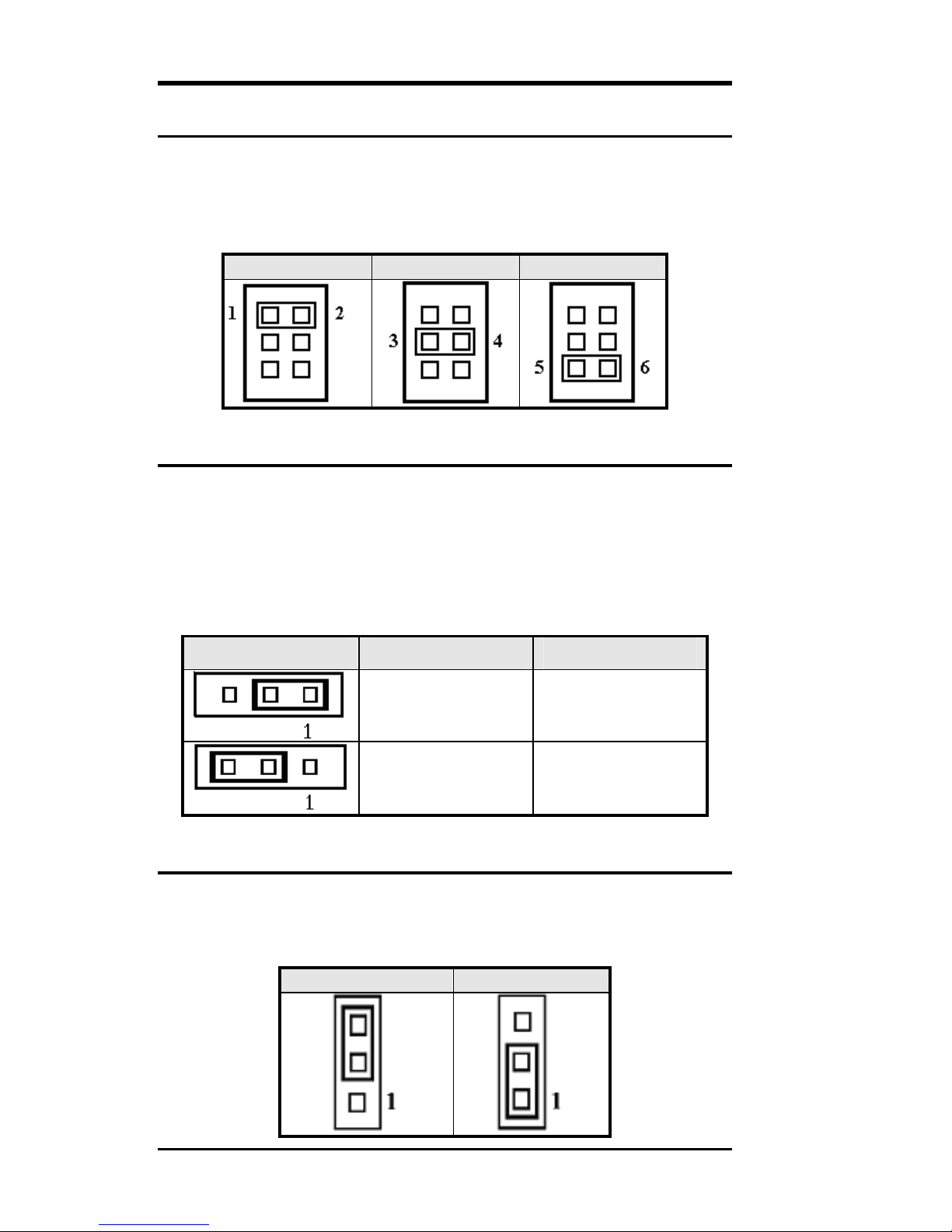
JP1, JP2: COM Power Selection
JP1, JP2 can be used to select the COM supply power: +5V,Ring-IN or
+12V.
JP1: COM2 Pin9 power or Ring-IN
JP2: COM1 pin9 power or Ring-IN
+5V RI +12V
JP3: Clear CMOS RAM Data
This 3-pin Jumper allows the user to d isco n nect th e built-in 3V battery
power to clear the information stored in the CMOS RAM. To clear the
CMOS data: (1) Turn off the system power, (2) Remove Jumper cap
from pin1&2, (3) Short the pin2 and pin3 for three seconds, (4) Put
Jumper cap back to pin1 & 2. (5) Turn on your computer, (6) Hold
Down <Delete> during boot up and enter BIOS setup to enter your
preferences.
JP3 Setting Function
Pin 1-2
Short/Closed
Pin 2-3
Short/Closed
Normal Operation
(default)
Clear CMOS
Content
JP4: LCD PANEL Power Selection
JP4 can be used to select the Panel LCD supply power: +3.3V or
+5V.The default setting is on +3.3V.User need to check the LCD panel
spec and adjust this jumper to make Panel work i n specified power rail.
+3.3V +5V
12 ISA-E5 User`s Manual
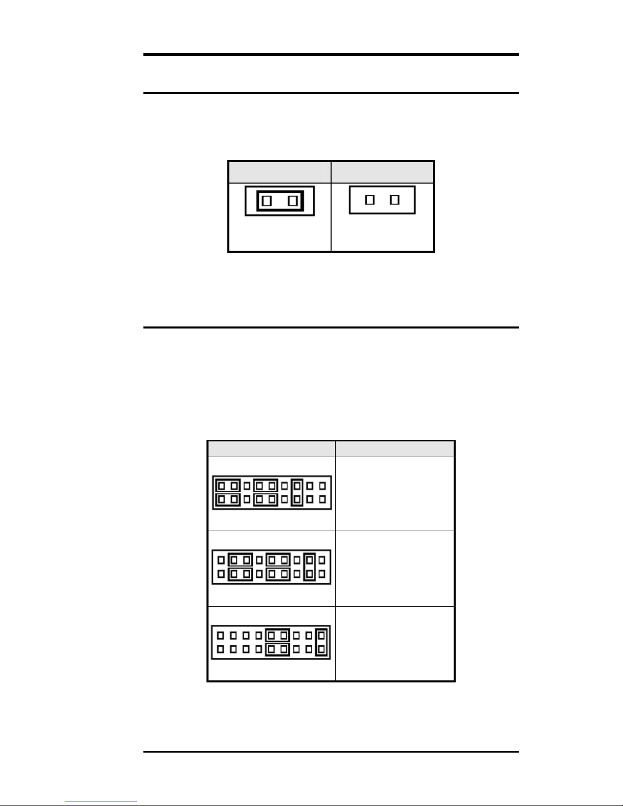
JP5: CF Card Mode Selection
This Jumper is to select the CF works as Primary Channel Master
device or Slave device.
Master Slave
1
JP5
1
JP5
COM2MODE1: RS232/RS422/RS485 Protocol Selection
COM2 supports multi-protocols, includes RS232, RS422 and RS485,
while COM1, COM3. COM4 support diffused RS232 protocol.
The Protocols of COM2 can be set up through jumpers.
COM2MODE1: COM2 Protocols selection.
The pin-out for each mode is illustrated on next chapter.
COM2MODE1 I/F TYPE
17 1
RS-232
ISA-E5 User`s Manual
18 2
17 1
RS-422
18 2
17 1
RS-485
18 2
13
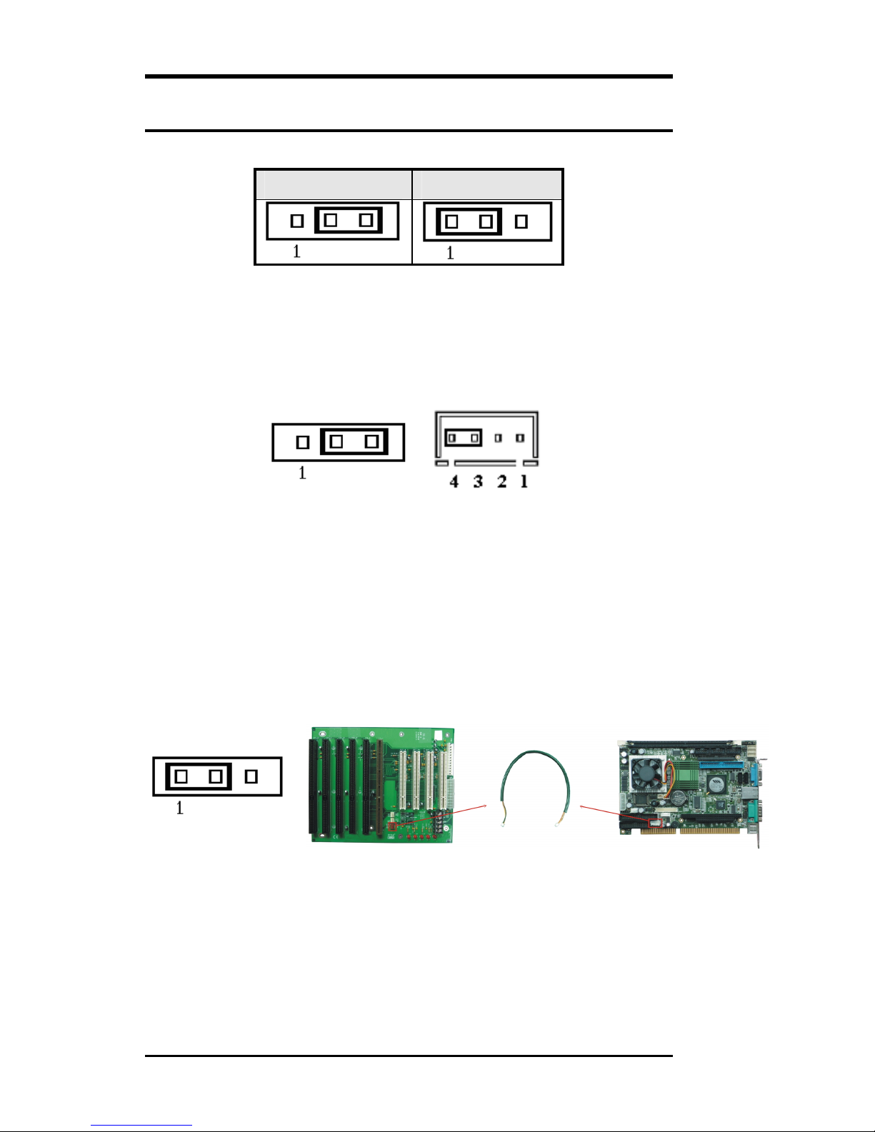
PWRMODE: AT Mode Selection
AT Mode ATX Mode
When PWRMODE are chosen as AT Mode, please make sure short
Pin3 & Pin4 of ATX-PWR. The setting is illustrated as below :
AT-MODE ATX-PWR
When PWRMODE are chosen as ATX Mode, you will need a cable to
connect control signal and 5VSB standby power from backplane to
ATX-PWR connector on ISA-E5. In the mean time, you will need to
short Pin1 & Pin2 on PWRMODE selection jumper.
ATX-MODE BACKPLANE CABLE ISA-E5
14 ISA-E5 User`s Manual

Connectors on the ISA-E5
The connectors on the ISA-E5 allow you to connect external devices
such as keyboard, floppy disk drives, hard disk drives, printers and etc.
The following table lists the connectors on ISA -E5 and t heir respective
page number.
Connector Locations on the ISA-E5..................................16
Front Panel Connector........................................................17
BACKLIGHT Connector...................................................18
IrDA Connector................................................................ 19
SATA1, SATA2 Connectors..............................................19
EIDE Connectors ...............................................................20
COM1 Serial Port...............................................................22
COM2 Serial Port...............................................................22
COM3, COM4 Serial Ports................................................23
USB12, USB34 Connectors...............................................23
Floppy Drive Connector.....................................................24
Parallel Port Connector......................................................25
PS/2 Keyboard & Mouse Connector..................................26
VGA Connector .................................................................26
INT_VGA Connector .........................................................27
INT_KBMS Connector......................................................27
AUDIO Connector.............................................................27
CPU FAN Power Connector..............................................28
System FAN Power Connector..........................................28
ATX Power Connector.......................................................28
PWR_IN1 Connector.........................................................30
PWR_IN2 Connector.........................................................30
LAN- RJ45 Connector .......................................................31
LAN RJ45 LED ................................................................31
LVDS LCD Connector.......................................................32
CF-II Connector.................................................................33
ISA-E5 User`s Manual
15

Connector Locations on the ISA-E5
16 ISA-E5 User`s Manual

Front Panel Connector
The front panel of the case has a control panel, which provides light
indication of the computer activities and switches to change the
computer status.
PWR HDD PWR Reset
BTN LED LED
ATX Power ON/OFF Button
This 2-pins connector acts as the “Power Supply On/Off Switch”
on the ISA-E5 single board computer card. When pressed, the
switch will force the single board computer card to power on.
When pressed again, it will force the single board computer card
to power off.
PWR BTN
Pin #
Signal Name
1 5VSB
2 PWRBTN
IDE Hard Disk LED Connector
This connector connects to the hard drive activity LED on control
panel. This LED will flash when the HDD is being accessed.
IDE LED
Signal Name
Pin #
3 VCC
4 HDDLED
ISA-E5 User`s Manual
17
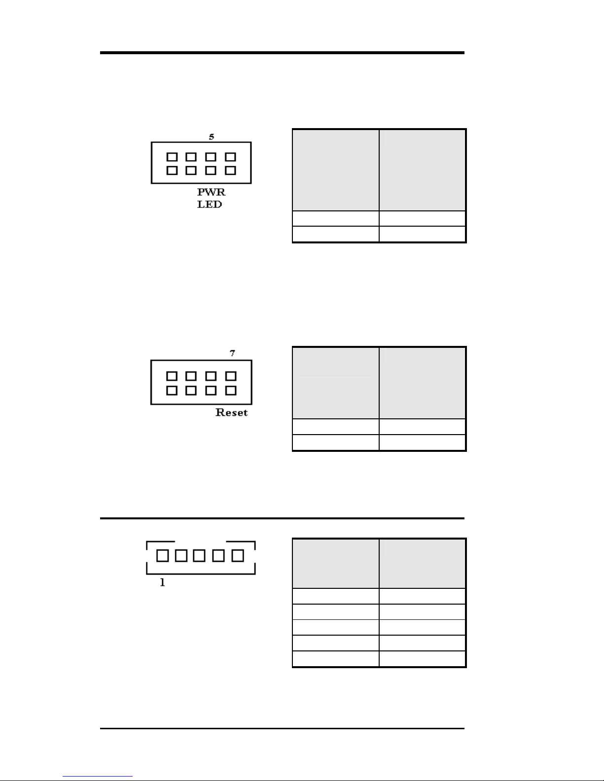
Power-On LED
This connector allows users to connect to Front Panel Power
indicator.
PWR LED
Signal Name
Pin #
5 PWRLED
6 Ground
RESET Switch
The reset switch allows the user to reset the system without turning
the main power switch off and t hen o n. Orientation is not required
when making a connection to this header.
RESET
Signal Name
Pin #
BACKLIGHT Connector
7 SYS_RST
8 Ground
Pin # Signal Name
1 +12V
2 GND
3 Brightness
4 ON/OFF
5 GND
18 ISA-E5 User`s Manual
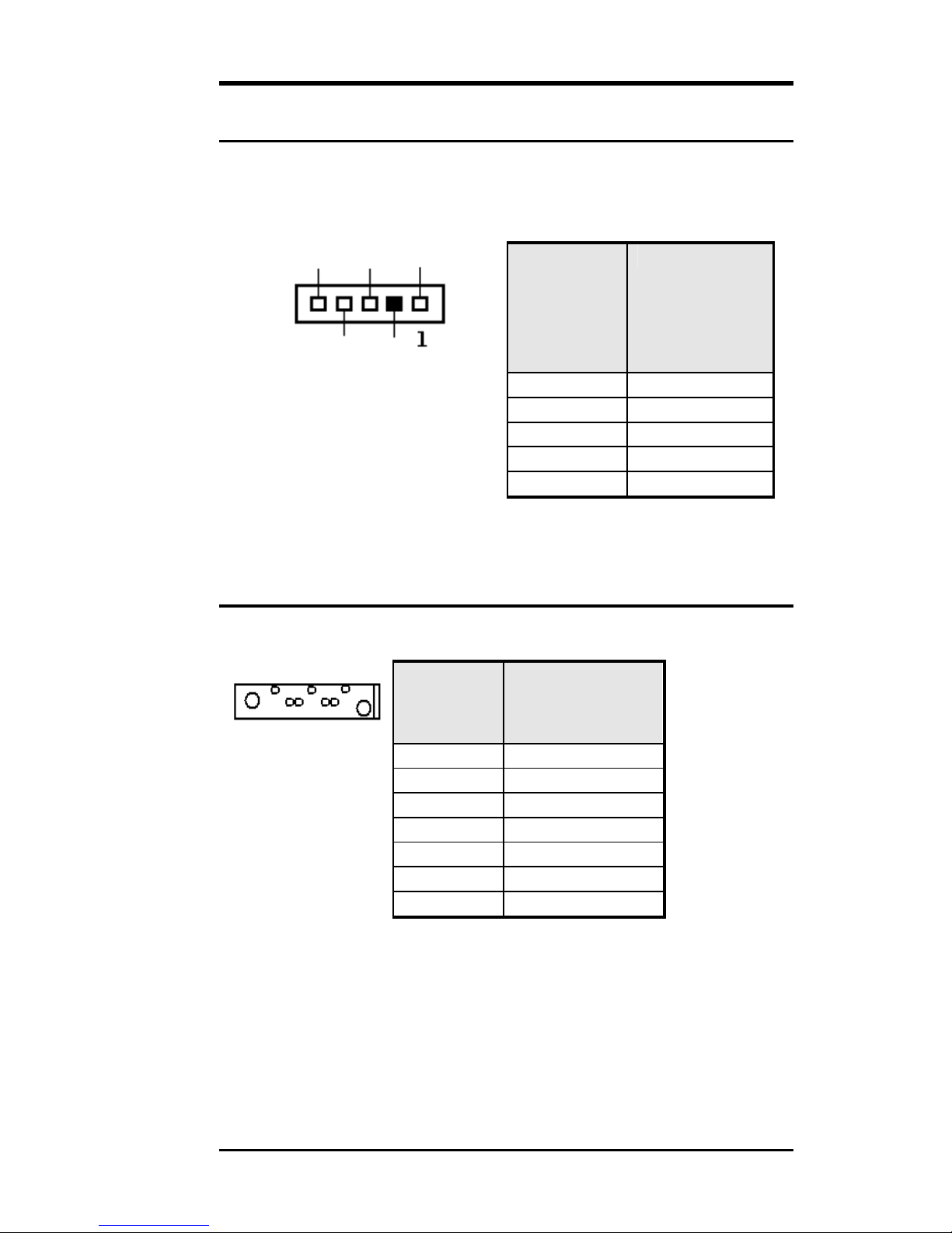
IrDA Connector
This connector is used for an IrDA connector for wireless
communication.
IRTX IRRX +5V
IrDA Pin # Signal Name
GND FIR
1 +5V
2 FIR
3 Ir RX
4 Ground
5 Ir TX
SATA1, SATA2 Connectors
1 7
Pin # Signal Name
1 GND
2 SATARX+
3 SATARX4 GND
5 SATATX6 SATATX+
7 GND
ISA-E5 User`s Manual
19
 Loading...