

Civco GUS G10-U2-EU, GUS G10VP-EU, GUS G14-U2-AC-EU, GUS G10VPL-EU, GUS G14-U3-EU Operator's Manual
...
or Transvaginal/Transrectal
Ultrasound Probes & Endoscopes
Operator’s Manual
Disinfection Soak Stations
F
REF:
G10-U2-EU
G10VP-EU
G10VPL-EU
G10ENT-EU
G14-U2-AC-EU
G14-U3-EU
G14KA-EU
G14KAL-EU
G14ENT-3-EU

GUS Disinfection Soak Station™
Contents
Principle of Operation ............................................................................................................ 3
Safety Precautions ................................................................................................................. 4
Setting up your GUS............................................................................................................... 5
Upon Delivery .............................................................................................................................................................. 5
GUS Components ......................................................................................................................................................... 5
Wall Mounting Installation Instructions ................................................................................. 6
Using High Level Disinfectants with your GUS ......................................................................... 7
For G10VP-EU, G10VPL-EU, G14KA-EU & G14KAL-EU ONLY ....................................................................................... 7
Step 1: Marking the Cable ........................................................................................................................................... 7
Step 2: Placing Probe in Container ............................................................................................................................... 7
Step 3: Filling the Containers –For ALL Units ............................................................................................................... 8
Step 4: Ready for Use - For ALL Units ........................................................................................................................... 9
Disinfection ........................................................................................................................... 9
For G10VP-EU, G10VPL-EU, G14KA-EU & G14KAL-EU – ONLY ..................................................................................... 9
For G10ENT-EU, G14ENT-3-EU, G10-U2-EU, G14-U2-AC-EU, G14-U3-EU – ONLY ..................................................... 10
Rinsing ................................................................................................................................ 10
System Maintenance ........................................................................................................... 11
Repair and Modification ............................................................................................................................................ 11
Disposing of Used High Level Disinfectants ........................................................................... 11
Changing the Filters ............................................................................................................. 11
Cleaning .............................................................................................................................. 12
Limited Warranty ................................................................................................................ 14
APPENDIX A: TROUBLESHOOTING ........................................................................................ 15
Quick Trouble Shoot................................................................................................................................................... 15
APPENDIX B: SITE REQUIREMENTS ....................................................................................... 16
Environmental Conditions.......................................................................................................................................... 16
Ventilation Requirements .......................................................................................................................................... 16
Supply Ratings ........................................................................................................................................................... 16
Warning Symbols ....................................................................................................................................................... 16
Signal Word ............................................................................................................................................................... 16
APPENDIX C: GUS PRODUCT SPECIFICATIONS ....................................................................... 17
GUS Product Specifications ........................................................................................................................................ 17
UL Approval ............................................................................................................................................................... 18
CE Mark Approval ...................................................................................................................................................... 18
EC Representative ...................................................................................................................................................... 18
50010_F GUS 10-14 (International) Series
2

GUS Disinfection Soak Station™
Principle of Operation
The GUS System allows Ultrasound Probes and/or Scopes to be immersed in a high-level disinfectant
solution. The Probe and/or Scope is suspended in the soaking container, preventing damage to the
sensitive tip.
The system is designed to remove fumes from:
• Glutaraldehyde,
• Ortho-phthaldehyde (OPA),
• Hydrogen Peroxide,
• Peracetic Acid.
For the use of alternative high level disinfectants, please contact your local representative.
One of the containers is used for clean rinse water. This ensures that when the Probe or Scope is
removed from the unit for the final rinse, no high-level disinfectant will drip or off-gas.
The unit’s blower and carbon-filtration system removes fumes from high-level disinfectant solutions.
Blowers draw the fumes through the carbon filter where they are effectively neutralized and clean air
is returned to the room. No ductwork or external venting is required. The G10 series has two
blowers; the G14 series has three blowers.
50010_F GUS 10-14 (International) Series
3
GUS Disinfection Soak Station™
Safety Precautions
Signal Word
The following signal words are used throughout this manual:
WARNING: Indicates a potentially hazardous situation which, if not avoided,
could result in death or serious injury.
CAUTION Indicates a potentially hazardous situation which, if not avoided,
may result in minor or moderate injury. It may also be used to
alert against unsafe practices or potential equipment damage.
NOTE: Indicates additional helpful information.
Warning Symbols: The meanings of the labels and symbols that appear on the
packaging and/or the system are as follows:
Dangerous electrical voltage
Protective Grounding
NOTE: Do not use the system for any purpose other than its intended use.
The GUS System is not intended for the storage of probes, moisture on the probes
can promote growth of bacteria.
Disconnect the power before replacing the filter or when servicing the unit.
Refer to the MSDS of the high-level disinfectant that you are using for additional
safety precautions.
NEVER place the probe into a dry tube. Make sure that the tip of your TOE probe is
straight before inserting. Use a fluid motion when inserting the probe to prevent it
from sticking in the tube.
50010_F GUS 10-14 (International) Series
4
GUS Disinfection Soak Station™
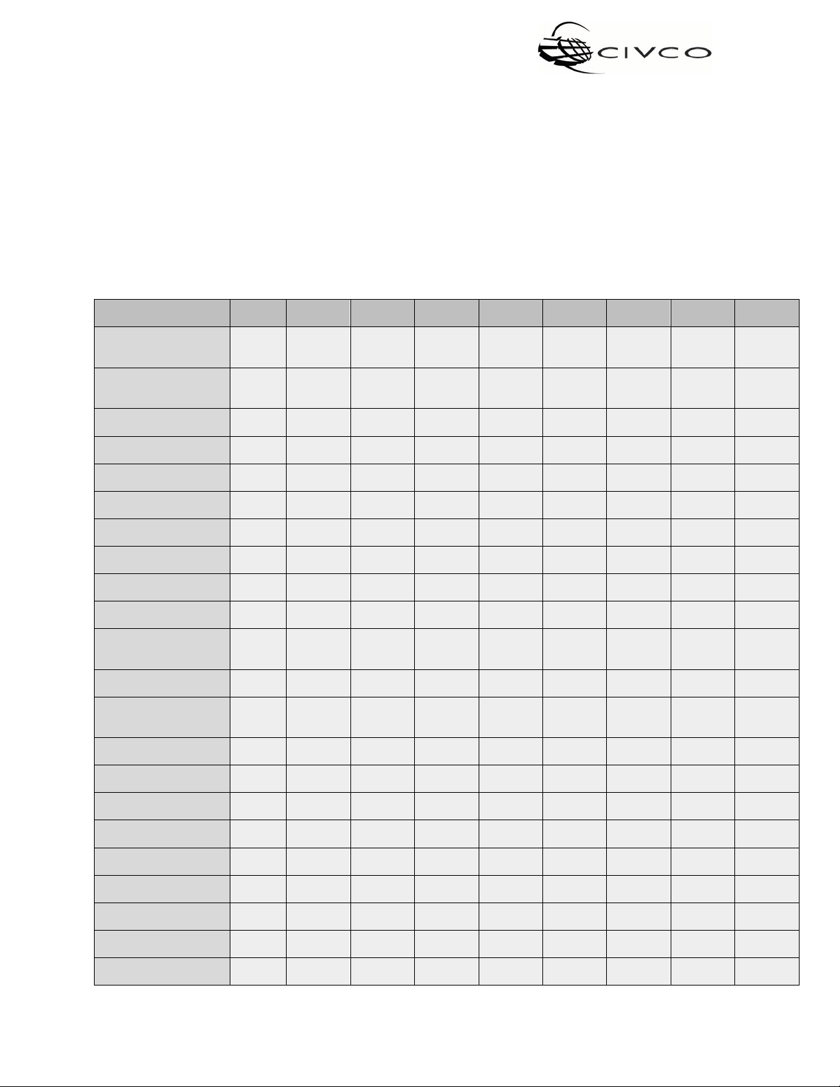
GUS Items
G10-U2EU
G10ENTEU
G10VP-EU
G10VPLEU
G14-U2AC-EU
G14-U3EU
G14ENT-3EU
G14KA-EU
G14KALEU
Containers with Caps.
Containers with Caps
48.3 cm Tubes
61 cm Tubes
Keys for Safety Door
Philips Screwdriver
Warning Card
Filter Installed In Unit.
Power Cord
Operator’s Manual
Customer Survey
Wall anchors
Labels
Red Pen
Shelf Adaptors
Spring Clips
Test Strip Clip
Stoppers
Foam Pad
Funnel
Cleaning Brush
Tong
Setting up your GUS
Upon Delivery
Match all items in the package with those on the list of components given below. Inspect each item
for damage. If any components are missing or damaged or if you have any questions, do not use the
system; immediately contact your local representative.
GUS Components
30.5 cm Soak/Rinse
43.2 cm Soak/Rinse
Warranty Card &
High Level Disinfection
2 2 3
2 3
2 3
2 2 3
2 2 2 2 2 2 2 2 2
1 1 1 1 1 1 1 1 1
1 1 1 1 1
1 1 1 1 1 1 1 1 1
1 1 1 1 1 1 1 1 1
1 1 1 1 1 1 1 1 1
1 1 1 1 1 1 1 1 1
2 2 2 4 3 3 3 3 5
1 1 1 1 2 2 2 2 2
1 1 1 1 1 1 1 1 1
2 2 2 2 2
2 2 2 2 2
1 1 1 1 1
2 2 2 3 3
1 1 1 1 1 1 1 1 1
1 1
1 1
1
50010_F GUS 10-14 (International) Series
5

GUS Disinfection Soak Station™
Wall Mounting Installation Instructions
NOTE: THESE UNITS MUST BE WALL MOUNTED
1. You will need the following items before attempting to install this unit:
Measuring tape Level Pencil or pen
2. Location selection:
• There must be a minimum of 10 cm of clearance on the left side of the unit to allow for access
to the On/Off switch and fuses, and 10.2 cm of clearance beneath the unit.
3. Measure up from the floor to the top of the unit approx. 139 cm (recommended) or to the
comfort level of the operator.
4. At that point,
For the G10 Series: using a level, draw a line approximately 21 cm long. Mark two points on
this line 20.3 cm apart.
For the G14 Series: using a level, draw a line approximately 35.5 cm long. Mark two points on
this line 33 cm apart, and a control mark 16.5 cm in from either of the outer marks.
5. Using the enclosed Phillips screwdriver, press the tip of the wall anchor through these two points
and turn clockwise until the anchor is flush with the wall.
6. Screw the two supplied Philips screws into the anchors. Back off the screws approximately
0.4 cm from the wall and align the unit mounting holes over the screws and tighten the screws.
(CAUTION: Do not over-tighten the screws.)
7. For masonry walls use a suitable lead or plastic shield and bolt. These shields are not supplied.
8. Insert empty soak and rinse containers in unit. For the G14 series, place the rinse container in the
middle. Apply the supplied labels as appropriate.
9. Display the Warning Card on the wall in a visible location directly above or beside the unit.
NOTE: Use of removable power cords not supplied by CIVCO Medical Solutions may
affect the safety and performance of this device.
50010_F GUS 10-14 (International) Series
6

GUS Disinfection Soak Station™
Using High Level Disinfectants with your GUS
CAUTION: The tip of your Ultrasound Probe and/or Scope is extremely delicate.
Failure to follow these steps may result in expensive Probe or Scope
damage. The connection between the strain relief and the Probe or
Scope may NOT BE WATERTIGHT. Do not fill the container above
this connection. Refer to Probe and/or Scope manufacturer’s
instructions.
For G10VP-EU, G10VPL-EU, G14KA-EU & G14KAL-EU ONLY
Step 1: Marking the Cable
It is VERY IMPORTANT to mark the cable of EACH Probe to be disinfected. This will allow you to easily
place the Probe into the container without it touching the bottom
1. Place the Probe gently into the empty container until it
touches the bottom.
2. Insert the cable between the front and back grip clips
by depressing the tab.
3. With the tab depressed, slide the cable up 1.5 cm.
4. Mark the cable with an indelible red pen just above
the front grip clip (pen included). Figure 1.
5. Remove Probe by releasing the tab and continue the
mark around cable.
.
Figure 1.
Step 2: Placing Probe in Container
1. Hold the cable with your left hand thumbnail just above
the red mark and with Probe in right hand. Figure 2.
2. Gently place the Probe into the container keeping red
mark above the grip clip. Figure 3.
3. Depress blue tab and place cable between the grip clip
with the mark just above the tab. Release tab and close
door. Figure 4.
Practice this two or three times before you put the
disinfectant into the container. This is really easier than it
sounds and will insure the safety of your Probe
50010_F GUS 10-14 (International) Series
.
7
Figure 2.
GUS Disinfection Soak Station™
Figure 3
Figure 4
Step 3: Filling the Containers –For ALL Units
1. Plug the power cord into the power inlet module, and plug the unit into a proper wall outlet.
Switch the unit on using the ON/OFF switch located on left side of unit. The green indicator will
light when the unit is operating
2. The G10 Series has two containers: one for disinfectant and one for rinse water.
The G14 Series has three containers: two for disinfectant and one for rinse water. The rinse
water container should be in the middle.
3. Some disinfectants require activation before use. Pour the disinfectant into the soaking
containers. DO NOT fill above the lower shoulder of the container. Figure 5
4. To prevent evaporation of disinfectant, always replace the screw caps/stoppers on the containers
after removing the Probes or Scopes.
NOTE: Always replace the screw caps on the containers before turning the station
OFF.
NOTE: Your GUS
the containers.
5. Use an appropriate test strip to test the efficacy of the disinfectant. Follow test strip
manufacturer’s Instructions For Use.
system should be left running as long as there are chemicals inside
6. Fill the remaining container with clean rinse water for the preliminary rinse. You MUST have one
container for rinse water. This ensures that when the Probe or Scope is removed from the unit for
the final rinse, no high level disinfectant will drip or off-gas.
50010_F GUS 10-14 (International) Series
8

GUS Disinfection Soak Station™
Figure 5
Step 4: Ready for Use - For ALL Units
Disconnect the cable from the ultrasound machine, the electrical connector may be placed on top
of the GUS unit in the padded compartment.
CAUTION
NOTE: Use of removable power cords not supplied by CIVCO Medical Solutions may
affect the safety and performance of this device.
NOTE: Follow your facility’s instructions for Personal Protective Equipment during
cleaning and disinfecting.
1. Remove any sheath or condom, wipe off gel.
2. Follow Probe or Scope manufacturer’s instructions on how to pre-clean Probe or Scope properly
It is very important to follow the Probe or Scope
manufacturers’ instructions for cleaning, disinfecting and
rinsing your specific Probe or Scope. The following is a guide
only.
3. Wash or wipe Probe or Scope with enzymatic cleaner prior to disinfection.
Disinfection:
For G10VP-EU, G10VPL-EU, G14KA-EU & G14KAL-EU – ONLY
1. Place the Probe or Scope gently into the soak container using the grip clips (See Step 2 - 4),
close and lock the door.
2. Soaking time is dependent on your facility’s infection control guidelines and the high-level
disinfectant Instructions For Use.
50010_F GUS 10-14 (International) Series
9

GUS Disinfection Soak Station™
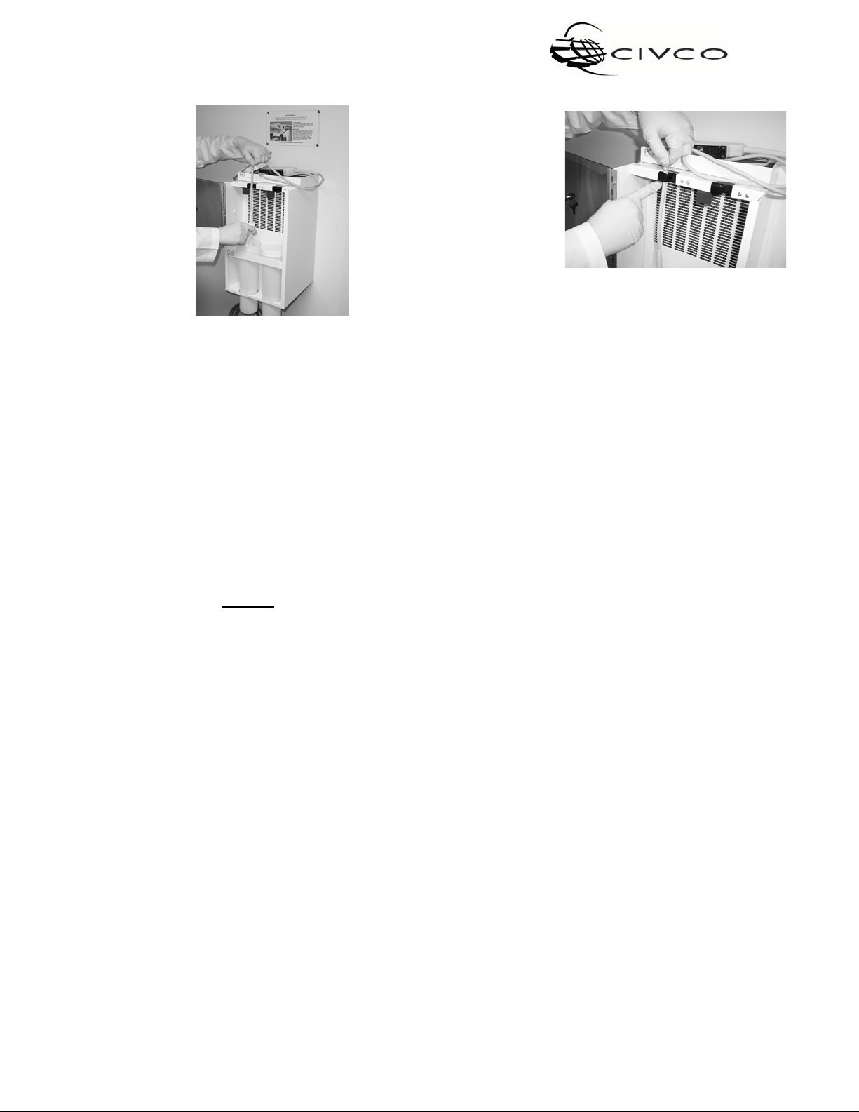
For G10ENT-EU, G14ENT-3-EU, G10-U2-EU, G14-U2-AC-EU, G14-U3-EU – ONLY
1. Place the scope into the soaking tube.
2. Align the light source cable with the top of the spring clip, push back on the blue plastic tab
and slide the cable into the cushioned cable holder. The rest of the light source can now be
coiled and placed in the padded compartment on top of the unit. You may also place the end
of the light source into the black plastic holder located on the side of the unit.
3. When testing the efficacy of your disinfectant, use the test strip clip provided with your
station to hold the test strip. Slowly lower the test strip into the disinfectant
NOTE: When not in use, place small black stoppers in the tubes or caps on
the soak containers to prevent evaporation.
.
Rinsing:
1. The initial rinse is done in the rinse container inside the GUS unit. This is an important step to
prevent drips and off-gassing when moving the Probe or Scope to the sink. After disinfection
is complete, unlock door, push back on the blue tab and lift the Probe or Scope up, shake it
gently to remove large drops of disinfectant. Then place it directly into the rinse container
while keeping your thumb on the red mark above the tab.
2. Rinse the disinfectant off the Probe or Scope by GENTLY swirling it around in the rinse
container. The Probe or Scope can now be removed, wiped with a paper towel, and given the
final rinses in the sink or trays according to the disinfectant manufacturer’s instruction.
3. Empty the rinse container in the GUS system, flush and then refill with fresh water.
4. For cleaning containers see ‘Cleaning’ section.
50010_F GUS 10-14 (International) Series
10

GUS Disinfection Soak Station™
WARNING
System Maintenance
Repair and Modification
Do not modify or repair the unit without reviewing with your local representative; contact your local
representative to purchase replacement filters and parts.
Before attempting to perform routine maintenance on the unit, thoroughly review and understand this manual
for complete familiarization with the unit and its operation. See ‘Cleaning’ section.
Disposing of Used High Level Disinfectants
In some areas, it is illegal to dispose of used disinfectants without first deactivating them. Deactivation
also protects the user from exposure to splashes and spills.
CIVCO Medical Solutions manufactures Glute-Out
comes in a convenient single-use bottle. Glute-Out
based disinfectants.
CIVCO Medical Solutions also manufactures Oxid Out
NO-QT) which comes in a convenient single-use bottle. Oxid Out is specifically for use with hydrogen-
peroxide based disinfectants. Contact your local representative to purchase neutralizer
®
, a glycine-based neutralizer (part # NG-QT) which
is specifically for use with glutaraldehyde and OPA
®,
a sodium-carbonate-based neutralizer (part #
.
Changing the Filters
GUS has a patented filter that, in normal everyday use will have a six-month life. For facilities that have
infrequent use, please call your local representative to set up an appropriate change schedule. Filters
must be changed at least once a year.
Put cap on the container containing your disinfectant. Turn the main
power OFF and disconnect the power cord from the electrical outlet.
1. Remove the foam pad from the top compartment.
2. Remove the top plate located in the top compartment by turning the captive screws
counterclockwise.
3. Remove the old filter by inserting fingers into the finger holes and pulling up. Filter may be snug
but should slide up with steady pressure.
4. Use a moistened soft cloth with a mild detergent and wipe down the whole front of the machine.
Also, wipe inside the machine behind the air intake panel. Dry all surfaces.
50010_F GUS 10-14 (International) Series
11

GUS Disinfection Soak Station™
5. Replace with a new filter, making sure the airflow arrows are pointing to the rear of the machine.
6. Put the used filter into a plastic bag and dispose of it with other non-hazardous waste.
7. Replace the top plate and tighten the captive screws by turning clockwise. Replace the foam pad,
plug unit back in, and turn on the machine.
Cleaning
Turn the main power OFF and disconnect the power cord from
CAUTION
Remove and thoroughly rinse all containers in which disinfectant is
the electrical outlet.
held, even if all disinfectant has been previously neutralized.
Disinfectant residues can be hazardous.
The containers cannot be sterilized by autoclaving. Doing so will damage
them.
DAILY CLEANING:
1. Remove the rinse water container, empty and wash both the container and cap.
2. Use a moistened soft cloth with mild detergent and wipe down the area around the containers.
3. Wipe off any drips around the disinfectant container and cap and below the shelf.
4. Do not spray cleaning liquids on the intake area of the machine as this will damage the filter.
5. After drying the areas, replace the rinse water container.
Refer to Changing the Filters section for additional cleaning steps when changing the filter.
50010_F GUS 10-14 (International) Series
12

GUS Disinfection Soak Station™
CLEANING THE GUS CONTAINERS:
• The containers that are supplied with the GUS Disinfection Soak Stations can be cleaned by
the following methods: In an instrument washer/disinfector with a thermal
or
• Manually cleaning with soap and water. Use the cleaning brush provided for ENT tubes.
Rinse containers afterwards.
The water/rinse container should be cleaned at least daily or in accordance with your facility’s
guidelines. The container used for the disinfectant can be cleaned before refilling with fresh
disinfectant.
Most customers replace the containers at least once a year, particularly when using OPA because of its
propensity to stain. These are available from your local representative.
IMPORTANT: Thoroughly clean and rinse out the soak container. With the unit turned on, put the
clean soaking container back into place and refill it with fresh high-level disinfectant.
50010_F GUS 10-14 (International) Series
13

GUS Disinfection Soak Station™
Limited Warranty
CIVCO Medical Solutions warrants the GUS Disinfection Soak Station™ to be free of defects in
materials and workmanship under normal use, for a period of one year from the date of delivery.
This warranty does not include filters, acrylic, or disposal pump unless it can be determined that
failure is due to defects in material or workmanship.
If the system is not working correctly or is defective, contact CIVCO Medical Solutions, and we will
repair
or replace the unit at our option during the warranty period.
CIVCO Medical Solutions assumes no liability for consequential damages of any kind as a result of
the
use or misuse of the system by the purchaser, the purchaser’s employees, or any others.
THIS WARRANTY IS EXPRESSLY IN LIEU OF ALL OTHER WARRANTIES, GUARANTEES,
OBLIGATIONS OR OTHER LIABILITIES EXPRESSED OR IMPLIED, AND THERE ARE NO WARRANTIES
WHICH EXTEND BEYOND THE DESCRIPTION ON THE FACE HEREOF. WARRANTIES OF
MERCHANTABILITY AND OF FITNESS FOR A PARTICULAR PURPOSE ARISING FROM A COURSE OF
DEALING OR USAGE ARE SPECIFICALLY EXCLUDED.
This warranty does not cover conditions and damages resulting from any of the following:
•
Improper installation, delivery within the facility, or maintenance.
•
Any repair, modification, alteration or adjustment not authorized by the
manufacturer.
•
Misuse, abuse, accidents or unreasonable use.
•
Incorrect electric current, voltage or supply.
•
Failure to follow proper procedures for use outlined in this manual.
•
Consequential or incidental damages sustained by any person as a result of any
breach of this warranty.
Some states do not allow the exclusion or limitation of consequential or incidental damages, so the
above exclusion may not apply.
50010_F GUS 10-14 (International) Series
14
GUS Disinfection Soak Station™
APPENDIX A: TROUBLESHOOTING
Quick Trouble Shoot
If your GUS
1) Ensure that the unit is plugged into a live wall outlet.
2) Make sure the ON/OFF switch (located on left side) is on.
3) In the event that the unit is still not working, check the fuses.
a) The fuses are located on the left side of the unit in the power inlet module.
b) UNPLUG UNIT BEFORE REMOVING FUSE DRAWER.
c) Squeeze the two tabs on the fuse drawer and pull outward to remove the fuses.
d) If a filament is damaged, replace it with a CIVCO Medical Solutions approved Type FSF 5 x 20
4) If the unit is still not working, please contact your local representative.
is not running, check the following:
mm 1 amp 250VAC.
CAUTION
If your soak container or tube is leaking, do not use any high level
disinfectant in it. Call your local distributor immediately for a
replacement container or tube.
50010_F GUS 10-14 (International) Series
15

GUS Disinfection Soak Station™
APPENDIX B: SITE REQUIREMENTS
Environmental Conditions
• For indoor use only.
• Altitude up to 2,000 meters.
• Temperature range: 5°C to 40°C.
• Main supply voltage fluctuations not to exceed +/- 10% of the nominal voltage.
• Insulation over voltage category II.
• Pollution degree 2.
Ventilation Requirements
There must be a minimum of 10.2 cm clearance beneath the unit to allow for the clearance of the soak/rinse
containers and adequate airflow.
Supply Ratings
• G10 Series: AC 230/240V 0.5A 50/60Hz
• G14 Series: AC 230/240V 0.5A 50/60Hz
• Fuses: Two Type FSF 5 x 20mm 1 amp 250VAC
Warning Symbols
The meanings of the labels and symbols that appear on the packaging and/or the system are as follows:
Dangerous electrical voltage.
Hazardous area.
Protective Grounding.
Signal Word
The following signal words are used throughout this manual:
WARNING: Indicates a potentially hazardous situation which, if not avoided, could result in death or
serious injury.
CAUTION Indicates a potentially hazardous situation which, if not avoided, may result in minor or
moderate injury. It may also be used to alert against unsafe practices or potential
equipment damage.
NOTE: Indicates additional helpful information.
50010_F GUS 10-14 (International) Series
16

GUS Disinfection Soak Station™
150
Weight (kg)
APPENDIX C: GUS PRODUCT SPECIFICATIONS
GUS Product Specifications
GUS Model
Number of Probes
and/or Scopes soaked
Face Velocity (MPM)
Electrical (240V 50/60Hz)
G10-
U2-
G10ENT-EU G10VPL-EU
EU
1 1 1 1 2 2 2 2 2
13.7 13.7 13.7 13.7 15.2 15.2 15.2 15.2 15.2
0.5A 0.5A 0.5A 0.5A 0.5A 0.5A 0.5A 0.5A 0.5A
G10VP-
EU
G14KA-EU
G14-U2-AC-
EU
G14-U3-
EU
G14ENT-3-
EU
G14KAL-EU
Space & Weight Requirements
Width
Depth
Height (Installed)
(tubes empty)
28
cm
26.7
cm
cm
11 11 11 11 13.7 13.7 13.7 13.7 13.7
28 cm 28 cm 28 cm 40.6 cm 40.6 cm 40.6 cm 40.6 cm 40.6 cm
26.7 cm 26.7 cm 26.7 cm 26.7 cm 26.7 cm 26.7 cm 26.7 cm 26.7 cm
150 cm 150 cm 150 cm 150 cm 150 cm 150 cm 150 cm 150 cm
50010_F GUS 10-14 (International) Series
17

GUS Disinfection Soak Station™
HW Fisher & Company
Tel: +44 (0)20 7380 4963.
CIVCO Medical Solutions
UL Approval
USA and Canadian Standards Approved.
CE Mark Approval
CB Test Certificate reference E178331-A2-CB-1.
EN 61010-1:2010: Safety requirements for electrical equipment for measurement, control, and laboratory use —
Part 1: General requirements.
Electrical Equipment Designed for Use within Certain Voltage Limits Directive 2006/95/EC.
Electromagnetic Compatibility Directive 2004/108/EC.
EC Representative
102 First Street South
Kalona, IA 52247 USA
Tel: 1-800-445-6741
Fax: 1-877-329-2482
Website: WWW.CIVCO.COM
Copyright © 2017 All Rights Reserved.
®
is a registered trademark of CIVCO Medical Solutions.
GUS
All other trademarks are property of their respective owners.
Printed in the USA.
Acre House 11 - 15
William Road
London
NW1 3ER
50010_F GUS 10-14 (International) Series
18
 Loading...