

Civacon 891 Series Instruction & Maintenance Manual
API Assembly
1. Insert handle shaft through hole in body and place large e-clip on shaft
2. Apply flourosilicone grease (Dow Corning 3452 or equivalent) to quad ring, washer, handle shaft
and inside the hole in which the components are inserted. Press quad ring, washer and bearing
over shaft and into the hole in body until flange on bearing is flush with surface body
3. Place o-ring, washer, spring, hub, nylon washer over shaft. Position handle so the hole in the shaft
aligns with the hole in the handle and the slot in the hub. Insert the fulcrum pin into the hole and
secure it with the bowtie clip
4. Insert poppet bearing into the hole in the body, then insert the poppet assembly through the
spring and through the bearing
5. Insert pin through poppet shaft
6. Insert link 2 through poppet shaft and secure with pins
7. Insert link 1 into hole in handle shaft and put small e-clip on link 1 to secure it to the handle shaft
8. Place o-ring into slot on the body
9. Coat screws with NEVER SEIZE and attach nose piece to body with screws and lock washers
10. Verify proper operation as described in semi-annual inspection
11. Place float ball over one of the holes on the side of the body. Place the sight glass o-ring inside
the groove of the sight glass and place the sight glass over the four hole of the body. Secure the
sight glass with screws and washers
WARRANTY
All parts and products are thoroughly inspected and tested from the time raw material is received
at our plant, until the product is completed. We guarantee that all products are free from defects
in materials and workmanship for a period of one year from the date of shipment. Any product
that may prove defective within said one year period will, at our discretion, be promptly repaired,
replaced or credit given for future orders. This warranty shall not apply to any products which has
been altered in any way, which has been repaired by any party other than an authorized service
representative, or when such a failure is due to misuse or condition of use. We shall have no liability
for labor costs, freight costs or any other costs or charges in excess of the amount of invoice
for the products.
THIS WARRANTY IS IN LIEU OF ALL OTHER WARRANTIES, EXPRESS OR IMPLIED AND
SPECIFICALLY THE WARRANTIES OF MERCHANTABILITY AND FITNESS FOR A PARTICULAR
PURPOSE.
WARNING!!
CIVACON products should be used in compliance with the applicable federal, state and local
laws and regulations. Product selection should be based on physical specifications and limitations,
compatibility with the environment, and the material being handled.
CIVACON MAKES NO WARRANTIES OF FITNESS FOR A PARTICULAR PURPOSE.
12000PA
891 Series Flat Bottom Loading Adapter
Instruction & Maintenance Manual
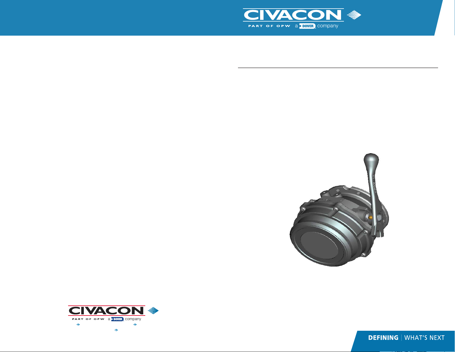
Product Description
Civacon’s 891 flat bottom API adapter design reduces product retention and
increases flow while unloading. The ergonomic handle smoothly opens the
poppet during manual operation and the hardened nose is rotatable for longer
service life. The poppet seal is easily serviced without removing the API from
the truck. The 891 adapter conforms to API 1004 and EN13083 regulations.
Civacon’s 891 is a direct replacement for the 861, 897 and all competitors’
bottom loading adapters.
TECHNICAL ASSISTANCE
If at any time during the installation a question arises that is not covered in this manual or with any
other applicable documents feel free to call the Customer Service Department or visit our website at
www.civacon.com.
In the U.S., call 1-888-526-5657 - In all other countries, call your local agent.
www.civacon.com 9393 Princeton-Glendale Road Hamilton, Ohio, USA 45011
NOTE: All information subject to engineering and/or other changes. All trade names are copyrighted. Patents Pending. ©2018 Civacon. ©2018 Delaware Capital Formation, Inc.
All Rights Reserved. DOVER and the DOVER logo are registered trademarks of Delaware Capital Formation, Inc., a wholly-owned subsidiary of Dover Corporation.
Phone: (800) 422-2525 Fax: (800) 421-3297
Manual
This manual contains the inspection, maintenance schedule and instructions
for repairing and replacing parts for all the 891 API adapters. The following
schedule, based on the environmental conditions in the northern United States,
is only a recommendation: Inspection and maintenance intervals must be
adjusted according to use and operating conditions. If any parts are damaged,
refer to the Annual Inspection and Maintenance section.
RevF Mar 2019
Semi-Annual Inspection
Visually inspect and test the valve for proper operation. This inspection can be done
without removing the API from the trailer. Before the inspection, ensure that all lines are
empty. Follow all safety procedures. If any of the following parts need to be repaired or
replaced, refer to the Annual Inspection & Maintenance section.
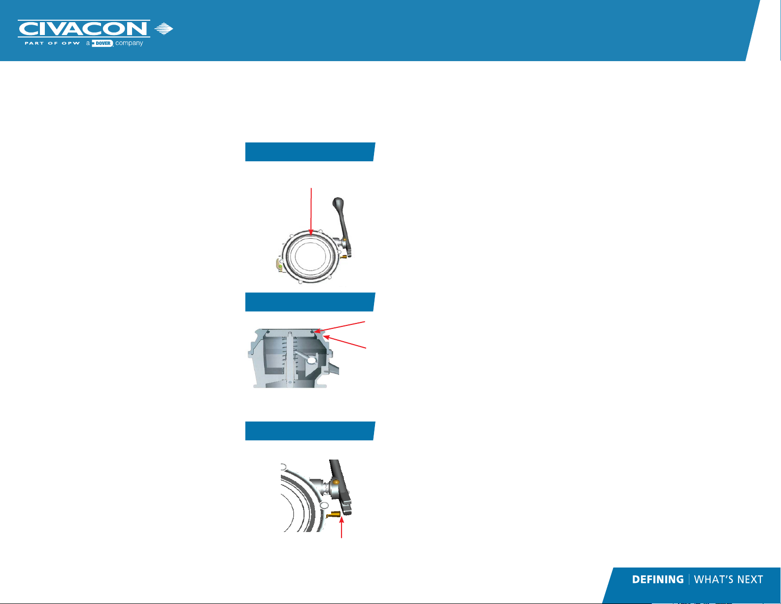
Visual Inspection
1. Inspect the nose external sealing surface for dents or
gouges which could interfere with interfacing equipment
API Nose Surface
External Sealing Surface
Figure 2
or cause leaks. See Figure 2.
2. Inspect the backside of the nose (as shown in Figure
3) for excessive wear from the loading coupler. Its hard
coated surface should be free of gouges and grooves
which could cause leaks. If gouges and grooves exist, the
adapter end should be rotated or replaced. Inspect the
inside sealing surface (as shown in figure 3) for wear.
3. Inspect stop pin for excessive wear or damage. The
handle should remain in the open position when placed
on top of the stop pin. If the valve does not remain open
Backside of Adaptor End
Figure 3
because the stop pin is worn, replace the pin. The gap
between the stop pin and handle should be at least 3/16”
(4.87mm) as shown in Figure 4.
Physical Inspection
1. Use the handle to open and close the API several times.
The handle should move smoothly.
2. Open the API with the handle as if unloading. Release
the handle from the latched position allowing the poppet
to slam shut. The poppet should close and center itself.
3. Open the valve by pushing on the poppet with a soft
API Handle Gap
Figure 4
nonmetallic tool as far off center as possible and allow the
poppet to slowly close. Repeat several times, the poppet
should center and re-seat every time.
Available 891 Repair Kits
• 891LPRK Poppet/Link Repair Kit
• 891ORK O-Ring Repair Kit
• 891HRK Handle Repair Kit
• 891SRK Handle Shaft Repair Kit
• 12489 Handle Stop Pin
3/16”
(4.87 mm)
minimum
• 11550 API Nose
Inside
Sealing
Surface
Coupler
Surface
Annual Inspection
1. Remove API from the trailer, and inspect it at the workbench
2. Keep the API in the closed position
3. Remove the six screws and lock washers from the nose. When the nose is removed the
poppet assembly will extend less than 1/4” (6.3mm)
4. Remove o-ring from the body
5. Remove the small e-clip and slide link off of the handle shaft
6. Disassemble poppet assembly. Remove the clevis pins located at the end of the poppet
assembly by depressing the spring loaded wedge. Slide link out of the poppet shaft.
Remove poppet assembly and spring
7. Inspect and replace poppet o-ring as needed. Do not damage the poppet o-ring groove
when removing the o-ring. Do not twist the o-ring when installing
8. Inspect the sealing surface of the nose for wear as shown in Figure 3, page 2
9. Inspect the poppet shaft for scoring or contamination. Wipe off any contamination, if
shaft is scored a 600 grit or finer polishing cloth may be used
10. Inspect inside of the poppet bearing for wear or foreign material. Wipe off any
contamination and replace bearing if necessary
11. Remove large e-clip
12. Remove handle assembly from the body
13. Remove bowtie clip and pin to disengage handle
14. Inspect quad ring and washer for wear and contamination and replace if needed
15. Inspect surface of handle shaft and inside surface of the hub and bearing for wear.
Hub should move freely over the shaft. Wipe off any contamination, polish with 600
grit or finer polishing cloth or replace as needed
16. Inspect nylon washers, o-rings, spring, and fulcrum pin for repair and replace as needed
17. For adapters that have sight glassed remove the screws and washers and inspect the
sight glass for wear or cracks. Inspect the o-ring and float ball for wear or cracks and
replace as needed
Installation Procedure
1. Remove nuts, bolts and washers from existing API Adapter
2. Remove API Adapter and gasket. Thoroughly clean mounting flange
3. Install new gasket (P/N 9095)
4. Position new API Adapter with notch in mounting flange oriented to the top position
5. Install nuts, bolts and washers
CAUTION:
OVERSIZED MOUNTING HARDWARE COULD CAUSE DAMAGE TO THIS VALVE DURING ASSEM-
BLY. MOUNTING HARDWARE TO BE NO LONGER THAN 1-1/2 IN (38mm) LONG. SEE MANUAL
FOR ADDITIONAL DETAILS.
CAUTION:
DO NOT WELD ON OR AROUND THIS EQUIPMENT WITHOUT PROPER ELECTRICAL GROUNDING.
FAILURE TO DO SO WILL RESULT IN DAMAGE TO THE API ADAPTER.
 Loading...