

City Theatrical SHoW DMX Neo D2, SHoW DMX Neo D4 Quick Start Manual
SHoW DMX Neo®
Wireless and Wired DMX
D2 and D4 Dimmers
Wireless SHoW DMX Neo Dimmers
The wireless SHoW DMX Neo D2 and D4 Dimmers have all the same features, except that the SHoW
DMX Neo D4 has four dimmer channels (A, B, C & D) while the SHoW DMX Neo D2 has two dimmer
channels (A & B).
The SHoW DMX Neo D2 and D4 Dimmers can be setup quickly with a SHoW DMX SHoW Baby®:
1. Connect your SHoW Baby to your DMX controller as a transmitter (if you’re using a different
SHoW DMX Neo unit as a transmitter, set the SHoW ID to 201 and proceed as below)
2. Power up the SHoW Baby and confirm it is receiving DMX (Data LED lit)
3. Set up your SHoW Baby and SHoW DMX Neo D4 Dimmer with clear line of sight between the
SHoW Baby antenna and the SHoW DMX Neo D4 Dimmer’s antenna
4. Orient the antennas of both units in parallel, either vertically or horizontally (do not point the
antennas at each other)
5. Connect +7.5 ~ 30VDC DC Power to the Dimmer using the two provided screw terminals.
Connect +VDC to the + (plus) Terminal and – (minus) VDC to the – Terminal. These terminals
will accommodate up to 14 AWG / 1.5mm
Be aware that the power supply voltage must match the rated voltage of the load. If you are
using 12V LED tape, use 12VDC power.
6. Confirm that at least two of the Received Signal Strength LEDs are lit and the Data LED is lit (if
few Received Signal Strength LEDs are lit, adjust the antenna positions so they are parallel and
check for radio barriers)
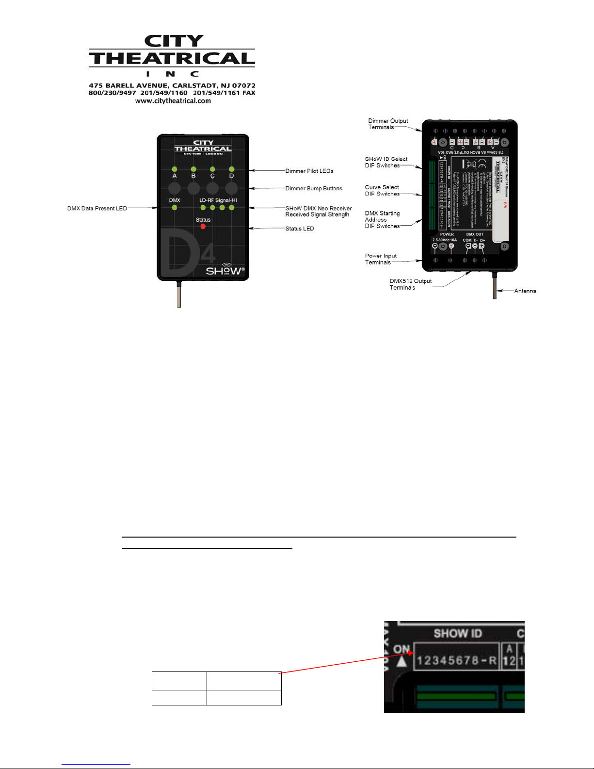
7. SHoW ID: Your new SHoW DMX Neo D4 Dimmer was factory preset at SHoW ID 201. If your
unit is no longer in factory default, set the SHoW ID DIP
Switch to 11001001 (SHoW ID 201). Note that the SHoW
ID DIP switches read left to right, while the binary number
in the SHoW ID chart below reads right to left.
SHoW ID
201 11001001
DIP Setting
87654321
2
wire. This DC power input is rated for 10A.
Quick Start Guide
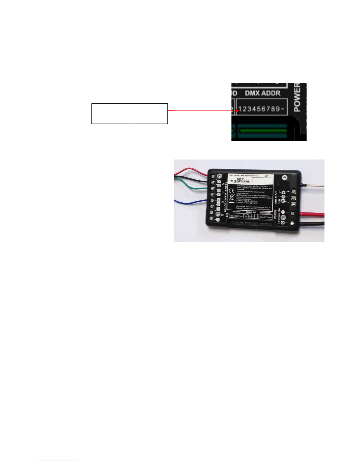
8. Set the DMX Starting Address DIP Switch to the desired starting address, referring to the DMX
DIP Switch Tables in the manual.
Note that the DMX Address DIP switches read left to right,
while the binary table below reads right to left
Start Address
1 000000001
DIP Setting
987654321
Turn power off before connecting your loads
Connecting 12V Three Color RGB Tape
12 Volt three color LED tape is provided
with a single +12VDC circuit and a –VDC
circuit for each color.
9. Connect the +12VDC circuit to any
one of the four + output terminals.
The + terminals are bussed, and
provide constant voltage. Note that
some tape comes pre-wired with
Black wire for the +12VDC circuit
while other tape comes pre-wire
with White w
ire.
10. Connect the R, G and B circuits
each to one the four – output terminals (in the case of four color tape, connect the A or W
circuit to the fourth – output terminal). The
– terminals are the PWM dimmed outputs of the D4 Dimmer. Note that some tape comes with
the R, G and B (and A or W) circuits in a different order than others.
11. Select the LED Curve for each dimmer channel used.
12. Power up your Dimmer and test your load connections with the bump buttons
13. If you wish to change the PWM frequency, use RDM or the MOD switch to select the frequency
desired.
Connecting Single Color Tape
12 Volt single color tape is provided with a single +VDC circuit and a –VDC circuit.
1. Connect the +VDC circuit to one of the + output terminals and connect the -VDC circuit to the
accompanying –output terminal. Up to two runs of single color tape can be driven and dimmed
by a D2 Dimmer.
2. Select the LED Curve for each dimmer channel used.
3. If you wish to change the PWM frequency, use RDM or the MOD switch to select the frequency
desired.
page 2 of 3
 Loading...