

City Theatrical Color Kinetics PDS-750-TR Operator's Manual
PDS-750-TR™
Touring Power Supply
Operator’s Manual
Rev 1.2
© 2004 City Theatrical, Inc.
Patent Pending

2
CONTENTS
The City Theatrical PDS-750-TR..............................................................................................3
Cautions...................................................................................................................................3
Compliance Certifications ........................................................................................................3
Compatibility with Color Kinetics Equipment ............................................................................3
Color Kinetics Fixtures Supported ........................................................................................3
Front Panel Controls ................................................................................................................4
Back Panel Features................................................................................................................5
Mains Power Requirements .....................................................................................................5
Connecting Color Kinetics fixtures to the PDS-750-TR.............................................................5
Operating Modes: CB, Pass Thru, or Stand-Alone..................................................................6
CB Mode ..............................................................................................................................6
Pass Thru Mode ...................................................................................................................6
Stand-Alone Effects Mode....................................................................................................7
Using the Mini-Zapi ................................................................................................................10
Installing the PDS-750-TR .....................................................................................................10
Software Options ...................................................................................................................11
Specifications.........................................................................................................................12
FIGURES
Figure 1, PDS-750-TR, Front Panel .........................................................................................4
Figure 2, PDS-750-TR, Back Panel..........................................................................................5
Figure 3 PDS-750-TR with C-Clamps ....................................................................................10

The City Theatrical PDS-750-TR
Thank you for using the City Theatrical PDS-750-TR™. Every effort has been made to
anticipate your questions in this manual, but if you have any questions that we don’t answer
here, or you want to discuss a special application, please feel free to contact us directly at City
Theatrical.
The CTI PDS-750-TR is a portable power supply unit provided with DMX 512 / Color Kinetics®
data management circuitry. It is designed to provide 24VDC power and standard DMX512
distribution connections with DMX field addressing capability for Color Kinetics Fixtures,
including ColorBlast® 6, ColorBlast 12, and iColor Cove® (other CK fixtures are also supported,
check with your favorite lighting shop or City Theatrical for details).
Cautions
The PDS-750-TR is intended for use only by qualified professionals. Connection, installation
and hanging of this equipment must be performed in accordance with all pertinent local, regional
and national safety codes and regulations.
The PDS-750-TR is intended for indoor use only.
Keep the unit dry! Do not operate the unit if it gets wet!
Do not operate in excessive heat/direct sunlight.
Be sure installation provides adequate ventilation. Both the front and the back side of the unit
must be clear of obstruction and allow free airflow.
There are no user-serviceable parts inside! Refer to qualified service personnel!
3
Compliance Certifications
ETL Listed, Conforms to UL 508A
cETL Listed, Certified to Can/CSA Standard 22.2 14-95
Compatibility with Color Kinetics Equipment
The CTI PDS-750-TR is produced under license and with the cooperation and approval of Color
Kinetics Inc. and is the only such entertainment power supply and control system approved for
such use. City Theatrical, Inc. and Color Kinetics, Inc. have made every effort to assure that the
CTI PDS-750-TR is fully compatible and will operate reliably with Color Kinetics CB and iColor
Cove fixtures.
Color Kinetics Fixtures Supported
The PDS-750-TR will power and control the following Color Kinetics Fixtures:
• ColorBlast 12: 12 units, 1 per output
• ColorBlast 6: 24 units, 2 per output
• ColorBurst 6: 24 units, 2 per output
• ColorBurst 4: 48 units, 4 per output
• Colorsplash 2: 24 units, 2 per output
• iColor Cove: 96 units, 8 per output
4
PDS-750 TR
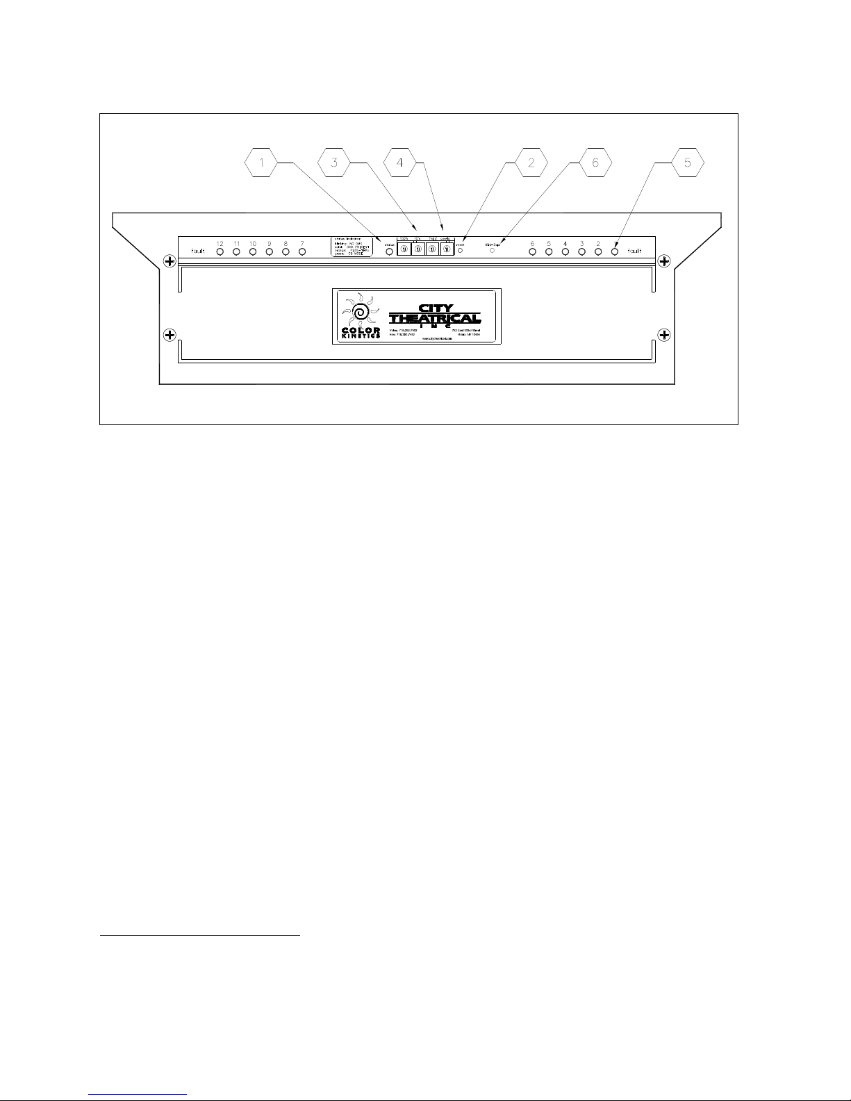
Figure 1, PDS-750-TR, Front Panel
Front Panel Controls
The PDS-750-TR front panel controls will generally look familiar to most professional users, with
a Pilot/Status Light, 3 BCD DMX Address Switch array, and a system reset switch. In addition,
the unit is provided with a Configuration BCD, overload indicators, and a Mini-Zapi™ Switch. All
the control functions are described below:
1. Pilot / Status Light:
On = Power Present, System running
Blinking = No DMX
Solid = DMX Present
Green = CB Mode
Orange = Pass Thru Mode
Alternating Red/Green = Stand Alone Mode
2. Reset Switch: Press to reset the PDS-750-TR’s system microprocessor
3. DMX Address Switches: Left to right = 100’s, 10’s, 1’s
Set address to 000 for Pass Thru mode
Set address to any valid address 001 – 4761 for CB mode
4. Configuration Switch: Selects Stand-Alone Routines. Also may be used for special
functions
5. Channel Overload Indicator: Lights if internal circuit breaker is tripped, indicating an
overloaded output. If tripped, disconnect load and allow unit to cool (~ 2 minutes). Circuit
1
The unit may be addressed to start at any DMX value up to 512, however addresses above 476 will
waste outputs, as DMX values will not exist for all outputs.
 Loading...