

City Theatrical AUTOYOKE User Manual

AUTOYOKE
with PARNel
User Manual
ver 1.0
752 EAST 133RD STREET BRONX, NY 10454
718/292/7932 800/230/9497 FAX:718/292/7482
email: info@citytheatrical.com
www.citytheatrical.com

TABLE OF CONTENTS
SECTION 1 SPECIFICATIONS
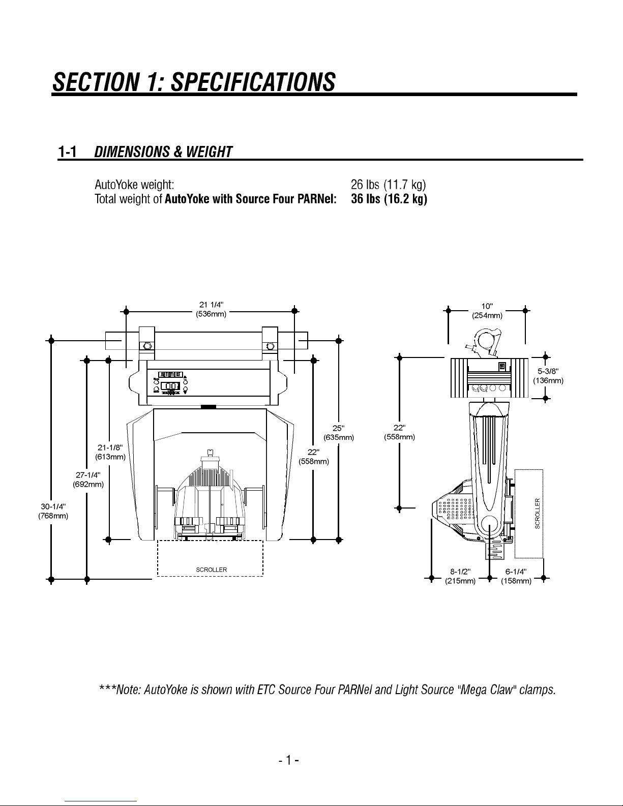
1-1 Dimensions and Weight
1-2 Compliance
1-3 Electrical
1-4 Protocol
1-5 Motors
SECTION 2 SAFETY
SECTION 3 INSTALLATION AND SET-UP
3-1 Unpack and inspect the shipping container
3-2 Balancing the System
3-3 Attaching a Color Scroller
3-4 Replacing the PARNel Lamp Housing Assembly on the Unit
3-5 Hanging the AutoYoke
3-6 Power cable
3-7 Data cable
SECTION 4 USER INTERFACE
4-1 Menu system
4-2 Address
4-3 Calibrate
4-3a Calibrate All
4-3b Calibrate a single attribute
4-3c AutoCalibrate
4-4 Invert
4-5 Resolution
4-5a 8 bit or 16 bit
4-5b DMX Smoothing values
4-6 Pan, Tilt, and Focus Limits
4-7 Software release
4-8 LED Display
4-8a Timeout
4-8b Brightness
4-9 Restore factory defaults
4-10 Error messages
p. 1
p. 2
p. 2
p. 2
p. 2
p. 3
p. 4
p. 5 - 6
p. 7 - 9
p. 10
p. 11
p. 11
p. 11
p. 12
p. 13
p. 14
p. 14
p. 15
p. 15
p. 16
p. 17
p. 17
p. 18
p. 19
p. 21
p. 21
p. 21
p. 22
p. 22
p. 23

SECTION 5 OPERATION
5-1 DMX channel assignments
5-2 Pan and Tilt
5-3 Default setting
5-4 Personality settings
5-5 Control channel
5-6 Encoders
SECTION 6 BEAMSPREAD AND COLOR CONTROL
AutoFocus
Scrollers
SECTION 7 MAINTENANCE
Software revisions
Spare parts
Lighting fixture
SECTION 8 WARRANTY
Limited Warranty
Procedure
p. 24
p. 24
p. 25
p. 25
p. 26
p. 27
p. 27
p. 27
p. 28
p. 28
p. 28
p. 28
p. 28
*** Trouble Shooting Guide and Balancing Guide are located after page 28.

1-2 COMPLIANCE
Conforms to UL STD 73, Eighth Edition - Motor Operated Appliances.
Certified to CAN/CSA C22.2 NO.: 68.92
ETL# 9801635
CETL# 9801635
CE, GS,
1-3 ELECTRICAL
· Working voltage: 100-240 VAC, 50/60 Hz
· Rated current: 1.3A
1-4 PROTOCOL
· USITT DMX512
· Start code: (00h)
· Maximum load: 32 fixtures per DMX link (See Section 3-7, Data Cable)
· Maximum length of DMX link: 2000' (See Section 3-7, Data Cable)
· Required control channels: 7 (16-bit) or 5 (8-bit) (See Section 3-7, Data Cable)
· Termination: 120Ω (See Section 3-7, Data Cable)
1-5 MOTORS
· High torque stepper motor, half stack
· Rated voltage DC: 8.7
· Step angle (degrees): 1.8
-2-

SECTION 2: SAFETY
· A moving light is a dangerous piece of equipment. It is for professional use only.
· If the supply cord is damaged, it must be replaced by the manufacturer or its service agent or a similarly
qualified person in order to avoid a hazard.
· Follow all safety procedures that apply to the lighting fixture, per its manufacturer’s instructions.
1. Refer to the lighting fixture’s user manual for all applicable safety information.
2. Maintain minimum safe distances.
· The AutoYoke with PARNel is designed for use only with the ETCSource Four PARNel. Using a fixture
other than the ETC Source Four PARNel WILL VOID THE AUTOYOKE WARRANTY.
· Always ground (earth) the AutoYoke electrically.
· Balance of the lighting fixture as mounted in the AutoYoke is critical to proper operation of the AutoYoke.
Attempting to operate the AutoYoke while the lighting fixture is out of balance presents a significant risk
of inaccuracy, increased motor noise and component failure. See Section 3-4, Balancing the System,
for complete information.
· Never lift the AutoYoke by the lighting fixture. Always lift and carry the AutoYoke by its two
handles, located on the sides of the power supply.
· Always suspend the AutoYoke from approved clamps secured to the designated points on the AutoYoke
power supply. See Section 3-5, Hanging the AutoYoke, for further information.
· Always use an approved safety cable when hanging the AutoYoke.
· Always disconnect the AutoYoke from AC power before service.
· Do not use DMX accessories that are not cited in this manual due to possible electrical incompatibility
with the AutoYoke.
· Do not allow the AutoYoke or its accessories to come into contact with moisture.
· Do not put flammable materials on or near the AutoYoke.
-3-
SECTION 3: INSTALLATION AND SET-UP
WARNING: Using a fixture other than the ETC Source Four PARNel with the AutoYoke
WILL VOID THE AUTOYOKE WARRANTY!
Addtional hazards include the following:
- Damaging both the AutoYoke and the lighting fixture
- Fixture detaching from the AutoYoke
- Fire hazard
3-1 UNPACK AND INSPECT THE SHIPPING CONTAINER
Verify that the AutoYoke has arrived complete and undamaged. The shipping container
should contain the following items:
- (1) AutoYoke with ETC Source Four PARNel
- (1) User's Manual
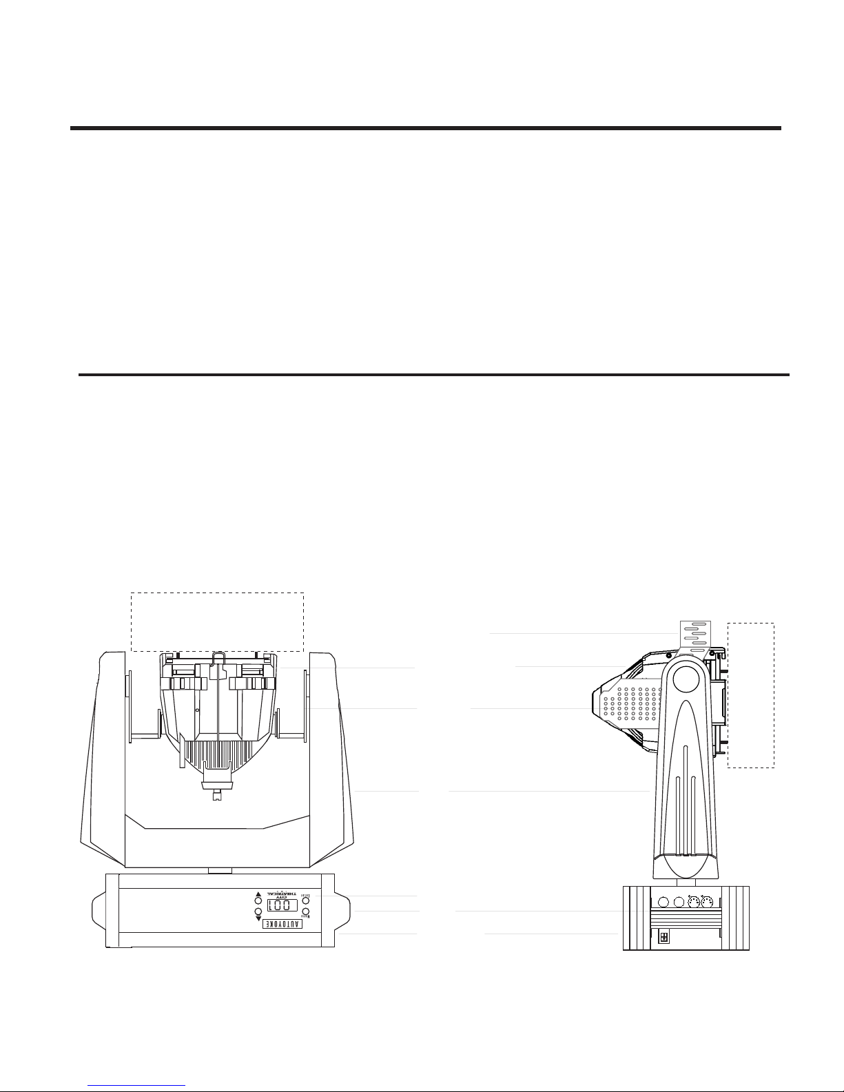
SCROLLER
connector box
Source Four PARNel
side arms
SCROLLER
yoke
control panel
handle
power supply
- 4 -
3-2 BALANCING THE SYSTEM
The AutoYoke with PARNel must be correctly balanced to insure proper operation. Follow the steps described below. There are a total of 6 (six) mounting holes, 3 (three) located on each side arm. They are arranged in a triangle
with the point of the triangle facing backwards. Use 1/4-20 x 1/2 -inch long, pan head screws in all of the mounting
holes. Failure to do so may result in poor performance of the of the AutoYoke. There are extra holes that are not
marked in the Balancing Guide to allow for balancing of the unit in the future for other accessories that were either
not available or not used when the Balancing Guide was published.
a) Refer to Balancing Guide table and figure at the last page of this manual.
b) Locate along the top of the table which color scroller will be used.
c) Locate along the side of the table which accessory will be used, if any.
*Note: Not all accessories are usable with all color scrollers. The combinations that are not valid are
marked with an "N A" (not applicable) in the table.
d) The intersection of the color scroller column and the accessory row will determine which set of holes
to use in the side arms for the proper balancing of the system.
e) Mount the PARNel-cradle assembly to the side arms using the set of holes determined from the previous
step. Make sure that the cradle is square with respect to the side arms.
f) Mount and secure the color scroller (if any) to the PARNel fixture and connect scroller to the connector box
of the AutoYoke. Please refer to Section 3-3, Attaching a Color Scroller/ Accessory, for instructions.
g) Mount and secure the accessory (if any). Refer to Section 3-3, Attaching a Color Scroller/ Accessory, for
instructions.
h) Tighten all hardware.
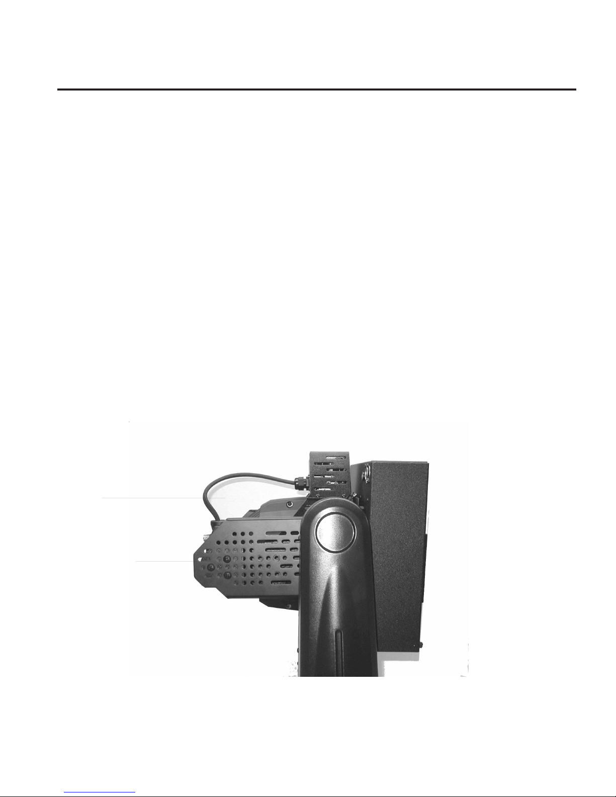
side arm
mounting screws
i) The lighting fixture is balanced when it free drifts to a near horizontal position (perpendicular to the Auto Yoke) or slightly front heavy. Operating an imbalanced AutoYoke will result in inaccuracy.
- 5 -

Some examples are as follows:
EXAMPLE 1
You will use the system without a color scroller and with or wothout a color frame. Look in the table for No
Scroller and No Accessory or Color Frame. The table will show that the PARNel-Cradle assembly should be mounted
to the side arms using the #1 set of holes. This is the default configuration when the unit is shipped from the factory
(unless special instructions have been provided to have the unit in another configuration prior to shipment). This
allows the user to run the AutoYoke straight from the box.
EXAMPLE 2
You will use the system with a Top Hat but the system is configured/balanced for No Accessory. Begin by
removing the screw at the point of the "V" on one side arm, and loosen the other two screws. Remove all the screws
from the #1 set of holes in the other side arm and loosely reinstall them in the #2 set of holes in accordance to the
Balancing Guide table. Remove the two screws from the #1 set of holes in the first side arm and tightly reinstall them
along with the third screw in the #2 set of holes, while making sure that the cradle is square with respect to the side
arms. Tighten the screws in the other side arm, again making sure the cradle is square. Mount and safety the Top Hat.
*Note: The method cited in Example 2 is only useful when moving from an adjacent set of holes. By leaving
some of the screws in loosely, it allows you to move the PARnel-cradle assembly to the other hole location easily.
If the new set of holes is further than the adjacent set of holes, all of the screws must be removed and reinstalled to
the new location.
EXAMPLE 3
You will use the system with a "Wybron" CXI color scroller but the unit is configured/balanced for No Accessory. Look in the table for the CXI color scroller then the top hat. The table will show that the PARNel-cradle assembly
should be mounted to the side arms using the #6 set of holes. Follow steps e through h of the instructions on the
previous page.
CXI Color Scroller- #6 set of holes
- 6 -
3-3 ATTACHING A COLOR SCROLLER
A color scroller is an optional accessory, and is not supplied by City Theatrical, Inc. See Section 6 for
further information.
THE AUTOYOKE SUPPORTS THE WYBRON FORERUNNER, WYBRON CXI (See cable note below),
WYBRON COLORAM II (See cable note below), RAINBOW PRO SERIES, AND CHROMA Q M-1 COLOR
SCROLLERS. THE AUTOYOKE SUPPLIES POWER TO THE SCROLLER; OTHER MANUFACTURER’S
SCROLLERS ARE NOT ELECTRICALLY COMPATIBLE. ATTEMPTING TO USE A SCROLLER OTHER THAN
THOSE LISTED ABOVE WILL POTENTIALLY DESTROY THE SCROLLER.
All AutoYoke-compatible scrollers that are not Wybron CXI nor Wybron Coloram II are referred to in this
manual as direct DMX scrollers.
See Section 4-2 for addressing.
1. Insert the scroller into the lighting fixture gel frame holder.
2. Secure color scroller to the fixture as tight as possible by use of plastic cable ties. This ensures that
the scroller will not move no matter what position it is in. Any extra movement on the scroller while
the unit is moving may cause inaccuracy due sudden weight shifts.
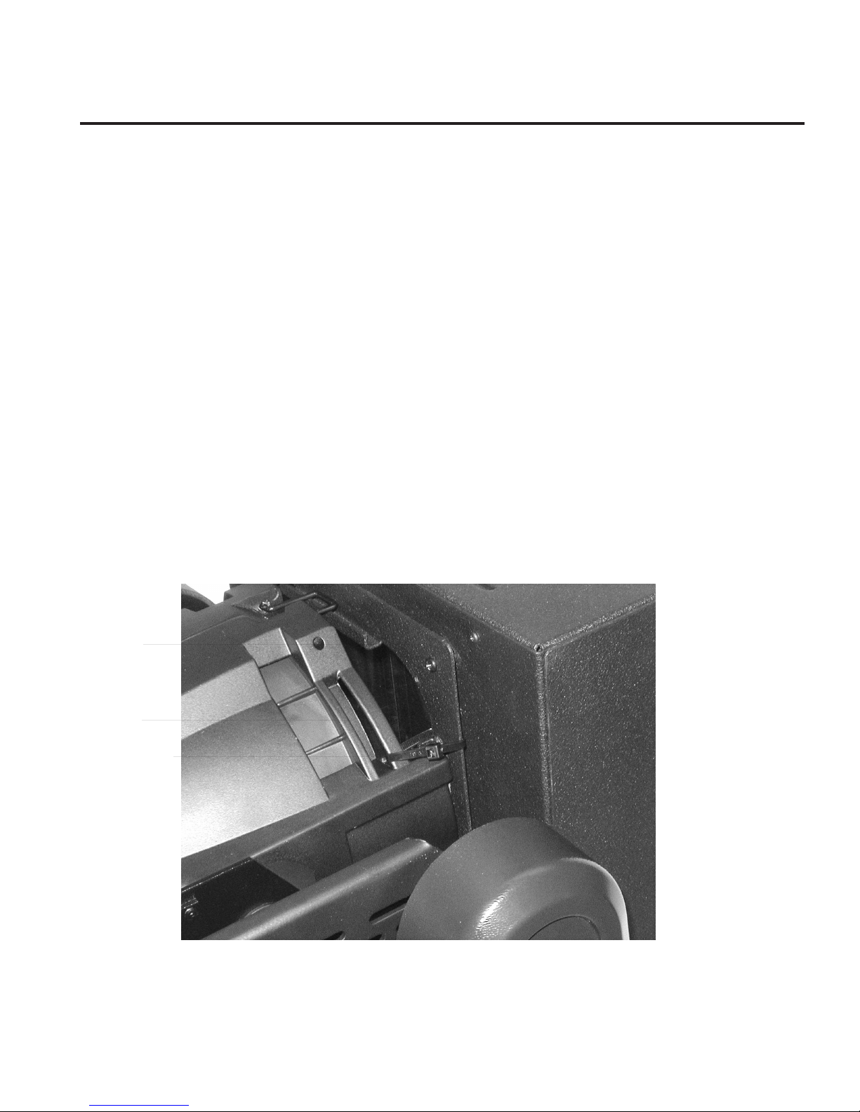
Loop the cables thru the adaptor plates then thru the tabs near the rim of the fixture. Use four attach ments points if possible. See pictures below on various attachment styles depending on the choice of
scroller.
adaptor plate
tab
cable tie
CXI, Coloram II
- 7 -
 Loading...