

Page 1
CitySync Ltd Technical Support T: +44 (0) 1438 347555 E: [email protected]
Document ID: 2115-017 Revision 02
Installation Guide for
CitySync 30 ANPR
Camera
Page 2

CitySync Ltd Technical Support T: +44 (0) 1438 347555 E: [email protected]
Document ID: 2115-017 Revision 02
Contents
Installation Guide for .............................................................................................................................. 1
CitySync 30 ANPR Camera ...................................................................................................................... 1
1. Component List ................................................................................................................................... 3
2. Introduction ........................................................................................................................................ 3
3. Connections ........................................................................................................................................ 4
4. Connection to PSU .............................................................................................................................. 5
5. Network Connection ........................................................................................................................... 6
6. Alignment ............................................................................................................................................ 9
7. Mounting ........................................................................................................................................... 10
8. Troubleshooting ................................................................................................................................ 10
9. Camera Specification (Subject to change) ........................................................................................ 11
Page 3

CitySync Ltd Technical Support T: +44 (0) 1438 347555 E: [email protected]
Document ID: 2115-017 Revision 02
1. Component List
ANPR Camera
RJ45 mating kit
2. Introduction
The ANPR camera comes pre‐aligned and set up for the stated distance. These distances relate to
standard UK number plates for use with ANPR software. The system is designed to provide an image
4m wide at the stated distance.
When NOT using standard UK plates please allow for difference in font size and adjust distance
accordingly.
For help or assistance with your particular installation please contact our technical support team.
There should be no need for the user to modify the camera set up in anyway, with the exception of
the network configuration which is detailed later.
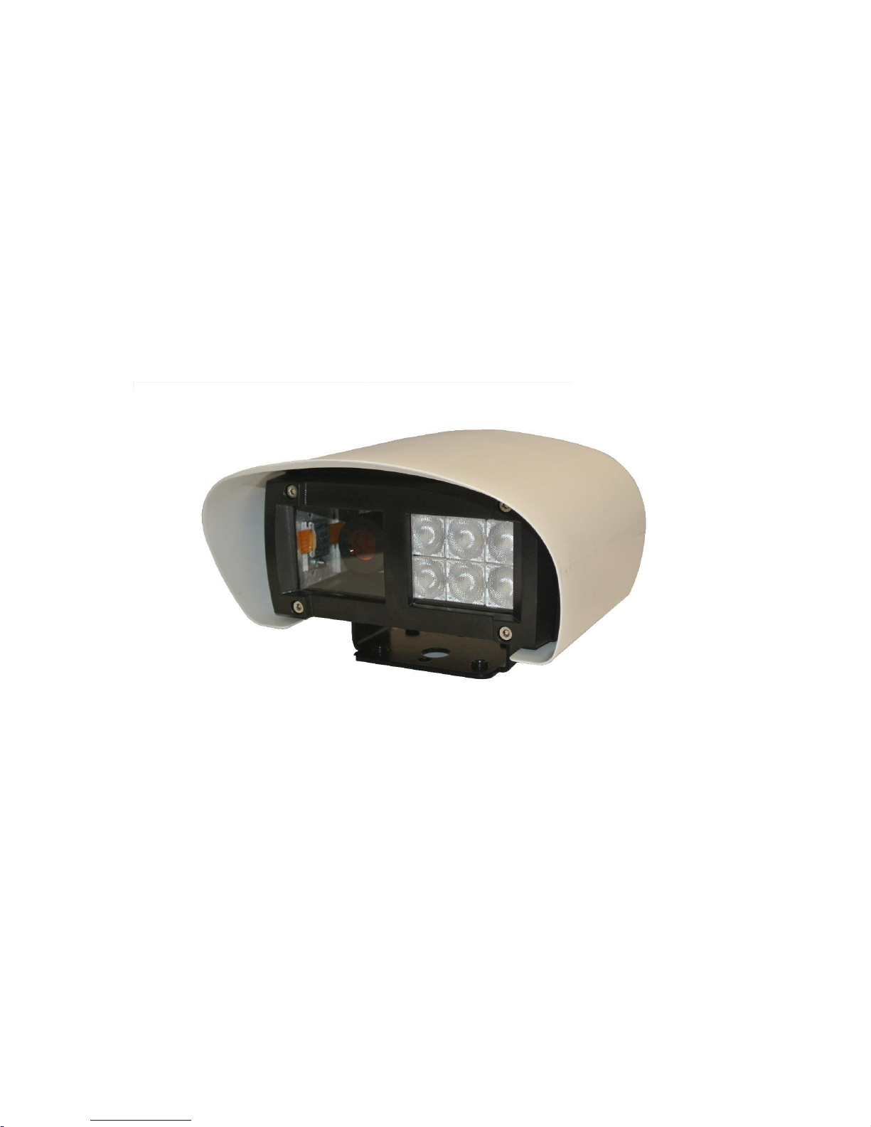
The ANPR camera is a combination of camera, lens and cool running Infra‐Red technology – all in a
protected housing, and calibrated for immediate use. The unit is supplied ready to run from a 24VDC
input.
The system is designed so that the camera and infra-red or white light illumination work in conjunction
to provide high quality pictures of the number plate on a 24 hour basis. In overcast days and in low
light – the system will still provide excellent images of the number plate. The LED’s are pulsed at a
very high frequency to achieve maximum performance with minimal power consumption.
The ANPR camera is designed to work with retro‐reflective number plates found in the UK, the
majority of Europe and most parts of US and Canada. If you are unsure about the nature of your
number plates, please do not hesitate to contact us.
Page 4
CitySync Ltd Technical Support T: +44 (0) 1438 347555 E: [email protected]
Document ID: 2115-017 Revision 02
3. Connections
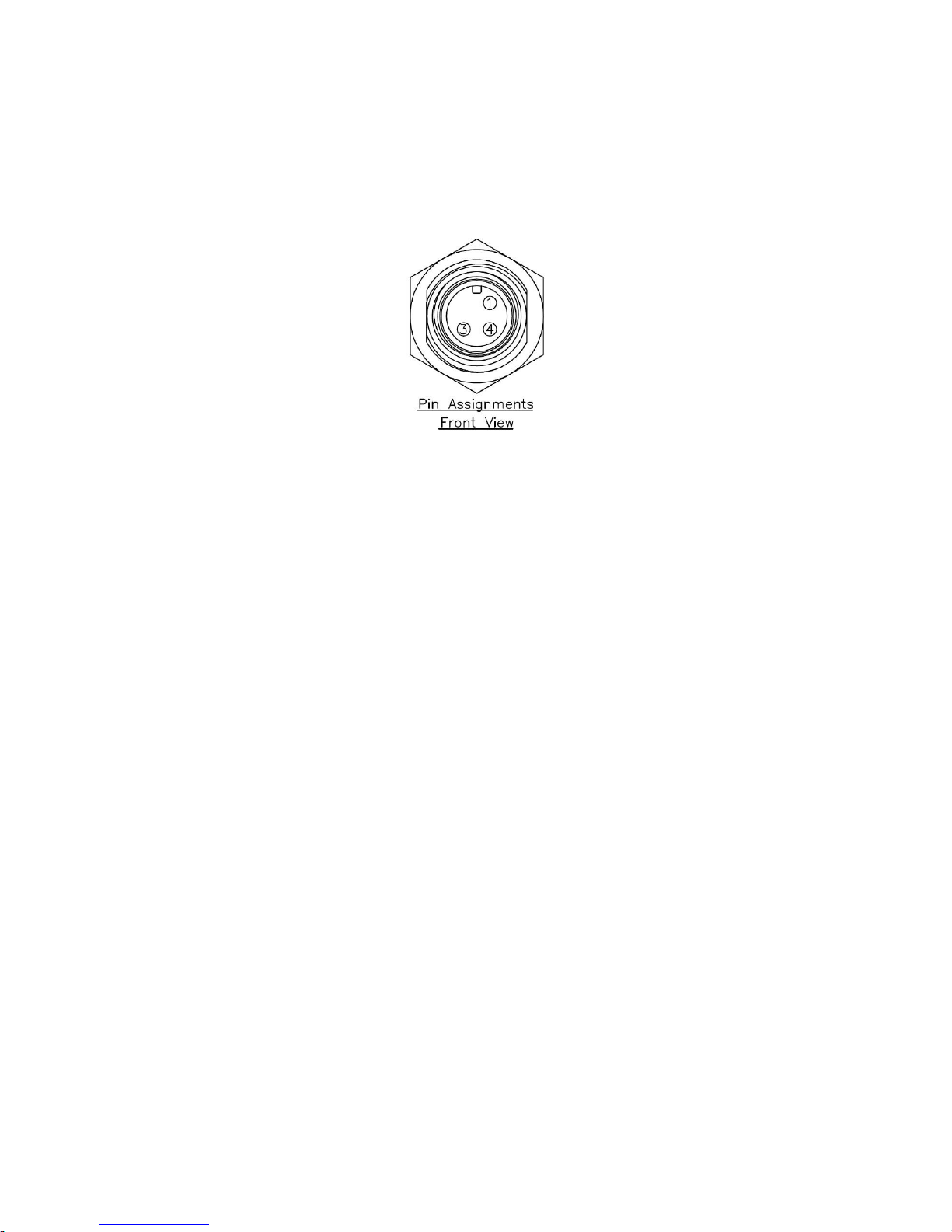
There are two connectors on the underside of the CitySync 30 camera:
1. 24VDC, three pin standard male M12, IP68 rated power connector.
Pin 1 = 24VDC
Pin 3 = 0VDC
Pin 4 = NC
An appropriate M12 cable connector, with or without a 5m cable, can be purchased from
CitySync. Please contact your account manager for more details. Alternatively, a standard M12
female connector can be independently purchased. It is recommended that the IP68 rating
should be maintained to preserve the rating of the unit. For reference, the manufacturer’s
part number for the M12 connector on the housing is RCP-5SPFFH-SCU7001.
2. An RJ45, IP67 rated network connector.
A mating kit is provided with the camera and must be used to maintain the IP rating of the
camera. A complete shielded network cable with RJ45 should be fed through the mating
connector, and then the sealing nut tightened to create a secure, weather proof grip onto the
cable.
Please see section 5 below for detailed network configuration.
Page 5

CitySync Ltd Technical Support T: +44 (0) 1438 347555 E: [email protected]
Document ID: 2115-017 Revision 02
4. Connection to PSU
The CitySync 30 camera requires 24VDC power. Its power consumption is less than 18W under all
conditions. An appropriate power supply unit can be purchased from CitySync Ltd, please contact your
account manager for more details.
Page 6
CitySync Ltd Technical Support T: +44 (0) 1438 347555 E: [email protected]
Document ID: 2115-017 Revision 02
5. Network Connection
The CitySync 30 camera must be connected to a 10/100/1000 Base-T(X) network that routes through
to the computer running the CitySync ANPR software.
The default IP address of the CitySync 30 camera is:
192.168.127.10
The address of every CitySync 30 camera on a given network must be unique and appropriate for
communication with the ANPR computer. Installed as part of the ANPR software suite is an application
called CitySyncFinder.exe. This can be found at:
C:\ANPR\Utilities\CitySyncFinder
The application can be used without the CitySync license dongle and can, for example, be copied over
to a laptop to aid on site installations. In addition to the application, “MDNS.dll” and “CsChilkat.dll”
must also be copied.
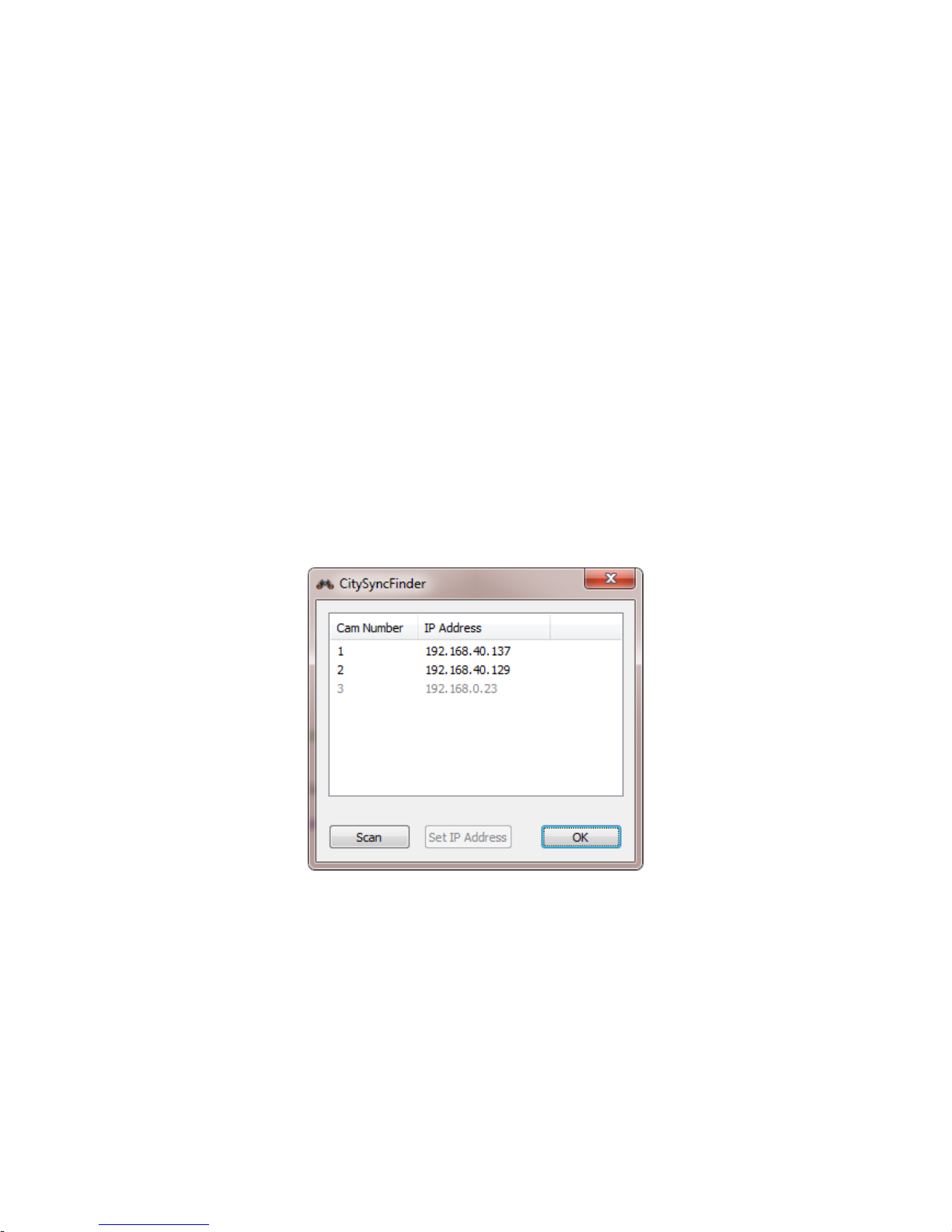
With the CitySync 30 connected to the network and powered up, start the CitySyncFinder application.
The application will automatically start scanning for cameras connected to the network and as they
are found they will be displayed as shown:
The cameras IP address can only be changed if its network matches the subnet of the computer
running the CitySyncFinder application. It is therefore recommended that the laptop/PC being used
has its IP address configured to:
192.168.127.xxx
Where xxx can be in the range of 1 to 255 (accept 10, which is used by the camera itself.)
The camera’s address can be programmed to any legitimate address. If the IP address of the camera
to be programmed does not match the computers subnet it will appear greyed out, as camera number
Page 7
CitySync Ltd Technical Support T: +44 (0) 1438 347555 E: [email protected]
Document ID: 2115-017 Revision 02
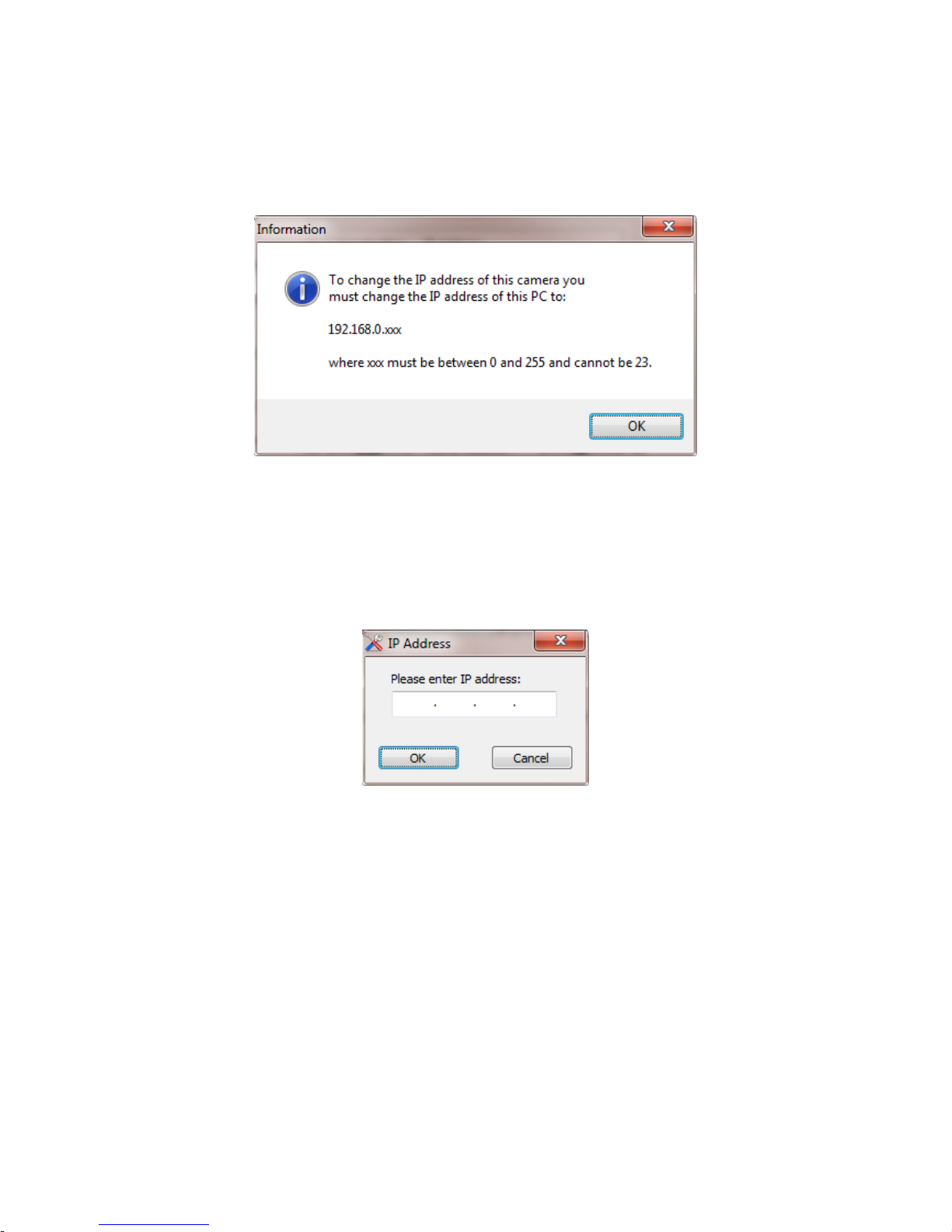
3 in the above example. Clicking on a greyed out camera in the list will produce an error window such
as the example below:
To change the IP address of a camera that is on the correct subnet, simply select it from the list and
click the “Set IP Address” button. This button will only be active if a selected camera is programmable.
The following window will appear:
Enter the IP address for the camera. This address should be the address required for final installation
and DOES NOT have to match the subnet of the computer running the CitySyncFinder application.
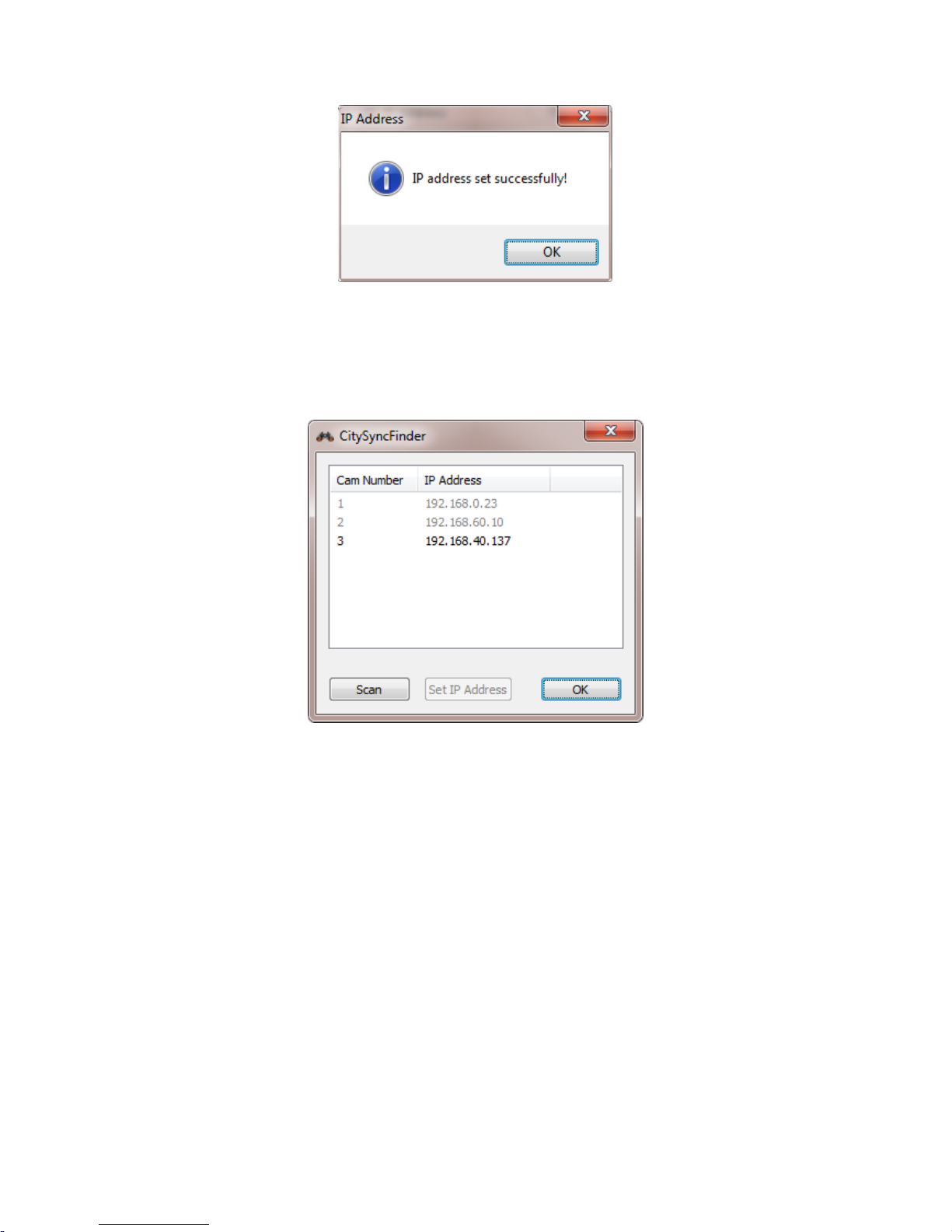
Click “OK” (or press enter) to programme the address, or “Cancel” to return to the main window. Once
the camera has been programmed the following will be displayed:
Page 8
CitySync Ltd Technical Support T: +44 (0) 1438 347555 E: [email protected]
Document ID: 2115-017 Revision 02
Click “OK” to return to the main window. The
CitySyncFinder application will now rescan for the cameras. As can be seen in the example below, the
camera that did have IP address “192.168.40.129” was changed to address “192.168.60.10”. This
address no longer matches the subnet of the computer, however, it is now the correct address
required for the final installation:
The network can be rescanned at any time by clicking the “Scan” button. Any cameras in the list will
be removed and a new scan performed. It can take up to ten seconds for all cameras to appear.
Page 9
CitySync Ltd Technical Support T: +44 (0) 1438 347555 E: [email protected]
Document ID: 2115-017 Revision 02
6. Alignment
For accurate number plate capture, do not exceed the quoted distances for the product. This is the
total distance from the ANPR camera to the target plate. The read distance should have been declared
when ordering the camera. The CitySync 30 camera will have been correctly zoomed and focused to
this distance. The camera cannot be opened to adjust these settings.
The angle from the ANPR camera to the target plate should not exceed 30 degrees.
The installation of the camera is most easily achieved during the day and using a laptop. It is
recommended that the laptop contains a copy of the CitySyncFinder.exe, to adjust the network
settings of the camera if required, and a copy of CitySyncViewer.exe to see live video from the camera.
The CitySyncViewer application can be found at:
C:\ANPR\Utilities\CitySyncViewer
To run this application on a laptop, please copy all the files from the above location onto the laptop.
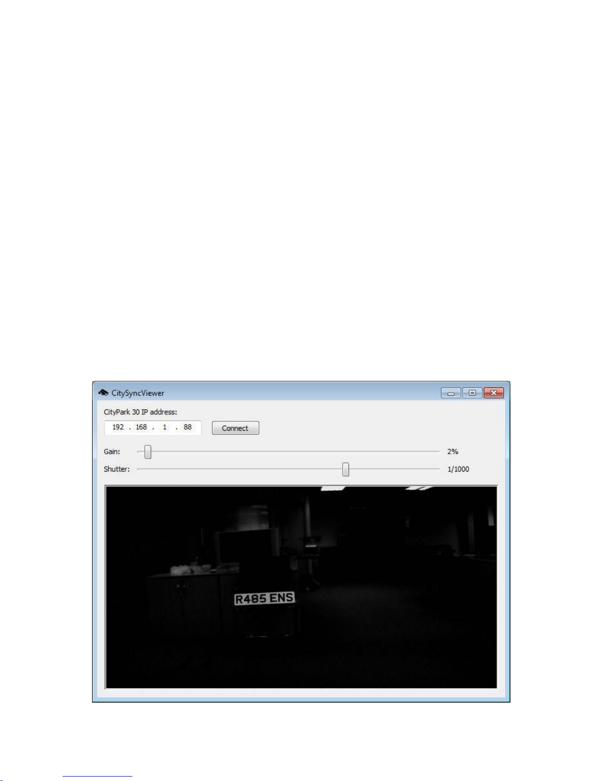
The laptop’s IP address must be appropriate for the network that the camera is connected to. With
the laptop connected to this network, start CitySyncViewer and enter the cameras IP address. Click
the connect button and in a few seconds live video should be displayed. Adjust the gain and shutter
speed so that the cameras field of view is clearly visible. It is recommended that a license plate is
placed in the target location. The alignment of the camera can now easily be achieved.
Page 10

CitySync Ltd Technical Support T: +44 (0) 1438 347555 E: [email protected]
Document ID: 2115-017 Revision 02
Once alignment has been complete it is suggested that a number of vehicles/plates are passed by the
camera and that correct plate recognition is achieved on the ANPR PC.
7. Mounting
A wall/pole mounting bracket, and a ceiling mounting bracket are available from CitySync. Please
contact your account manager for more information.
8. Troubleshooting
If you are not achieving the desired results, then check the following items:
1. Ensure total distance from the ANPR camera to target number plate does not exceed the
stated distance.
2. Ensure angle to number plate does not exceed ~30 degrees.
3. Ensure all connections sound:
Power input: red (+ve) and black (‐ve).
Ensure 24VDC input @ 1A
4. Ensure there are no obstructions in the way of the system which may interfere with IR.
5. Ensure the Infra-Red is on (A red glow should be visible)
Page 11

CitySync Ltd Technical Support T: +44 (0) 1438 347555 E: [email protected]
Document ID: 2115-017 Revision 02
9. Camera Specification (Subject to change)
Input: 24VDC, 1A.
Input Protection: Reverse polarity protected.
Powers Consumption: < 18W.
Sensor: 1/3” Aptina sensor.
Effective Pixels: 1920(H) x 1280(V)
1280(H) x 720(V)
Shutter Speed: Min - 1/500.
Max - 1/8000.
Video Output: MJPEG RTSP.
Min Illumination: 0 Lux operation with integrated IR.
Operating Temperature: ‐30 to +55oC.
Storage Temperature: ‐40 to +60 oC.
Weight (Incl. sunshield): 1.9kg
Weight (Excl. sunshield): 1.5kG
Dimensions (Incl. sunshield): 95mm x 198mm x 253mm (H x W x L)
Dimensions (Excl. sunshield): 77mm x 160mm x 195mm (H x W x L)
Opening up the camera housing is not recommended, and will void any warranty associated with the camera.
Camera and Lens settings are fixed and cannot be adjusted.
CitySync Ltd. Technical Support T: +44 (0) 1438 347555 E: [email protected]
 Loading...