

CityGrow CG201C, CG201S1, CG201DM, CG201SK, CG100R User Manual
...
32
fold size: 105 x146mm (-14pcs 210
Materiel: 80 gms paper
x146mm)
BK+BK Black on white
IMPORTANT NOTES
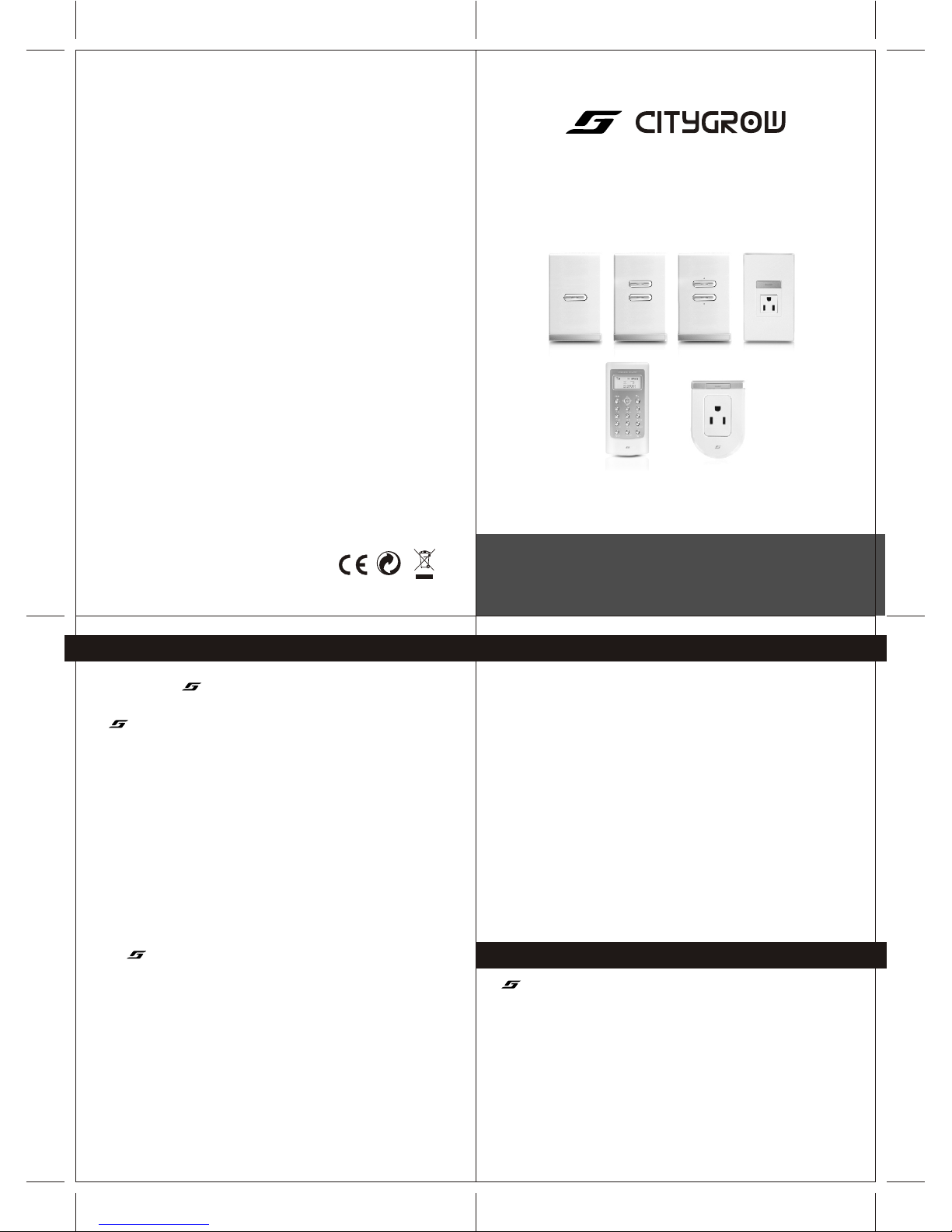
CG201 SERIES
Wireless Home Automation System
CityGrow Technology
www.citygrow.org
User Manual
PLANNING
To fully understand this product and its proper functions, please read this manual
before installation.
IMPORTANT
1.All products can be installed in standard BS4662 single switch boxes with
internal dimensions of 65mm x 65m x 35mm .
2.This device requires a neutral AC connection
3.This system requires a COORDINATOR, Model number is CG100C. The appearance
of this COORDINATOR is same as an one gang light switch. It works as the heart of
the system, it also works same as an one gang light switch. In order to identify the
COORDINATOR, you can either look at the model label at the rear cabinet, or
looking at the label "COORDINATOR"------- located inside the switch cover.
4.Within a network, you only need one COORDINATOR, more than one
COORDINATOR is not allowed.
WIRELESS REMOTE CONTROLLER
The Wireless remote controller operates at 2.4GHz, IEEE802.15.4, The operating range is
approximately 60 meters in an open area point to point, subject to environment
conditions. The control distance can be extended if you install more devices at
different locations.
PRODUCT SAFETY
In accordance with BS4662, all switch products can be installed in a standard switch
box. The unit complies with EN60669-1 , EN60669-2
(for switch, dimmer ) and BS1363( for AC socket). Furthermore, the effective radiated
power of the device does not exceed 100mW which complies with Office of the
Telecommunication Authority (OFTA), Hong Kong telecommunication order.
! WARNING! Improper use or installation can cause SERIOUS INJURY, DEATH or
LOSS/DAMAGE OF PROPERTY.
! WARNING! Install in accordance with all national and local electrical codes.
! WARNING! Have a professional electrician do the installation
! Important! CityGrow is NOT liable for any damage incurred with the misuse of this product.
! Important! Do NOT use a power screw driver to install this device
! Important! Pre-setup only could be done by professional worker or manufacturer agent.
TROUBLESHOOTHING
If unit does not function properly after installation, please refer to the
TROUBLESHOOTING GUIDE section
CHOOSING THE RIGHT LOCATION
It is important to select the right location for your light switch, dimmer and AC socket
It should be:
1.Easily accessible for programming and other operations.
2.In a location away from water, humidity, direct sunlight and dust.
3.The performance of wireless network relies on the wireless connection between the devices
location in your house. During installation, pay attention that the range and performance of
the wireless control system is highly dependent on
a. Distance between devices
b. Layout of the house
c. Walls separating devices
d. Electrical equippment located near the devices
e. Refer to Quick Installation Guide for the selection of installation location
12/6/09 VER 4.0 - US IB
FCC RF Radiation Exposure statement
This equipment complies with FCC RF radiation exposure limits set forth for an uncontrolled
environment. This equipment should be installed and operated with a minimum distance of
20 centimeters between the radiator and your body.
FCC ID: WSFCG201AS-EM
This device complies with Part 15 of the FCC Rules. Operation is subject to the following two
conditions: (1) this device may not cause harmful interfence, and (2) this device must accept
any interference received, including interference that may cause undesired operation.
This equipment has been tested and found to comply with the limits for a Class B digital device,
pursuant to Part 15 of the FCC Rules. These limits are designed to provide reasonable protection
against harmful interference in a residential installation. This equipment generates, uses, and can
radiate radio frequency energy and, if not installed and used in accordance with the instructions,
may cause harmful interference to radio communications. However, there is no guarantee that
interference will not occur in a particular installation. If this equipment does cause harmful
interference to radio or television reception, which can be determined by turning the equipment
off and on, the user is encouraged to try to correct the interference by one or more of the following
measures:
- Reorient or relocate the receiving antenna.
- Increase the separation between the equipment and receiver.
- Connect the equipment into an outlet on a circuit different from that to which the receiver
is connected.
- Consult the dealer or an experienced radio/TV technician for help.
IMPORTANT! Changes or modifications not expressly approved by the party responsible for
compliance could void the user's authority to operate the equipment.
REGULATORY COMPLIANCE
5544
66
CONTENTSCONTENTS
IMPORTANT NOTES
TROUBLESHOOTING
1. CG100 PACKAGE COMPONENTS
2. INTRODUCTION
3. UNDERSTANDING OF WIRELESS REMOTE CONTROLLER
3.1 BUTTONS
3.2 LCD DISPLAY ICONS
4. UNDERSTANDING OF THE DEVICES
4.1 TWO GANG LIGHT SWITCH
4.2 AC SOCKET
5. INSTALLATION
5.1 INSTALLATION METHOD
6.2.1 Test Converge
8.6.1 Edit Mood Name
8.6.2 Show Device Address
8.6.3 Edit Device Name
6. Device Configuration
6.1 Coordinator
6.2 Device
6.2.2 Configuration
6.3 Wireless Remote Controller
7. Grouping Device
7.1 Add Device to Group
7.2 ON/OFF Control
7.3 Dimmer Level Control
7.4 Get Status
7.5 Delete Device
7.6 Delete All Device in Group
7.7 Delete All Device in All Group
7.8 Advanced Function
7.8.1 Edit Group Name
7.8.2 Show Device Address
7.8.3 Edit Device Name
8. Mood Control (Scenario)
8.1 Add Device to Mood
8.2 Control Devices
8.3 Delete Device
8.4 Delete All Device in Mood
8.5 Delete All Device in All Group
8.6 Advanced Function
IMPORTANT NOTES
TROUBLESHOOTING
1. CG100 PACKAGE COMPONENTS
2. INTRODUCTION
3. UNDERSTANDING OF WIRELESS REMOTE CONTROLLER
4. UNDERSTANDING OF THE DEVICES
5. INSTALLATION
6. Device Configuration
7. Grouping Device
Mood Control (Scenario)
3.1 BUTTONS
3.2 LCD DISPLAY ICONS
4.1 TWO GANG LIGHT SWITCH
4.2 AC SOCKET
5.1 INSTALLATION METHOD
6.1 Coordinator
6.2 Device
6.2.1 Test Converge
6.2.2 Configuration
6.3 Wireless Remote Controller
7.1 Add Device to Group
7.2 ON/OFF Control
7.3 Dimmer Level Control
7.4 Get Status
7.5 Delete Device
7.6 Delete All Device in Group
7.7 Delete All Device in All Group
7.8 Advanced Function
7.8.1 Edit Group Name
7.8.2 Show Device Address
7.8.3 Edit Device Name
8.
8.1 Add Device to Mood
8.2 Control Devices
8.3 Delete Device
8.4 Delete All Device in Mood
8.5 Delete All Device in All Group
8.6 Advanced Function
8.6.1 Edit Mood Name
8.6.2 Show Device Address
8.6.3 Edit Device Name
77
22
33
66
77
88
8-98-9
99
10-1310-13
10-1110-11
12-1312-13
14-1514-15
14-1514-15
16-2116-21
9. System Setting
9.1 System Clock
9.2 Copy Setting
9.3 Reset
9.4 Memory Information
9.4.1 Registered Device
9.4.2 Device Added to GPs and Moods
9.5 Version
10. Timer Function
11. N-Way Configuration
11.1 Check Device
11.2 Remove N-Way Function of Device
11.3 Configure the N-Way Function
12. APPENDIX
12.1 Specifications--Device
12.2 Specifications Wireless Remote Controller
12.3 Troubleshooting Guide
39-4439-44
3939
4040
4141
4242
4242
4343
4444
45-4645-46
47-5147-51
4848
4949
50-5150-51
52-5552-55
5353
5454
5555
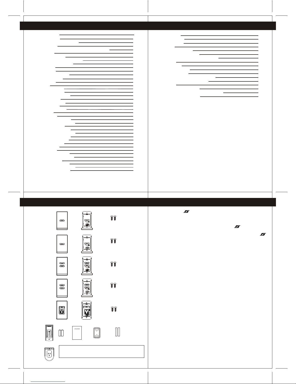
1.CG201 PACKAGE COMPONENT1.CG201 PACKAGE COMPONENT
Remarks: This diagram shows all of the choices that can be purchased,
which may not be same as your purchased package
Important: There should be only ONE coordinator in a system
Remarks: This diagram shows all of the choices that can be purchased,
which may not be same as your purchased package
Important: There should be only ONE coordinator in a system
CG201C
COORDINATOR
WIRELESS
SWITCH-ONE
GANG
CG201C
COORDINATOR
WIRELESS
SWITCH-ONE
GANG
Cover plateCover plate
Main unitMain unit
Screw x 2 Screw x 2
CG201S1
WIRELESS
SWITCH-ONE
GANG
CG201S1
WIRELESS
SWITCH-ONE
GANG
Cover plateCover plate
Main unitMain unit
Screw x 2 Screw x 2
CG201S2
WIRELESS
SWITCH-TWO
GANG
CG201S2
WIRELESS
SWITCH-TWO
GANG
Cover plateCover plate
Main unitMain unit
Cover plateCover plate
Main unitMain unit
Cover plateCover plate
Main unitMain unit
Screw x 2 Screw x 2
Screw x 2 Screw x 2
Main unitMain unit
Screw x 2 Screw x 2
CG201DM
WIRELESS
DIMMER
CG201DM
WIRELESS
DIMMER
CG201SK
WIRELESS
SOCKET
CG201SK
WIRELESS
SOCKET
CG201ASCG201AS
2.INTRODUCTION2.INTRODUCTION
Thank you for selecting product , this intelligent Home Automation system is working
on IEEE 802.15.4 Communication standard. It offers beneficial features like ....
1.Wireless control at 2.4Ghz
2.Wireless control distance can be extended by locating different devices at different
location , these devices form a communication network.
3.Bi-directional communication that you can either control or monitor the status of your
devices
4.Simple installation procedures
5.Simple wiring, extra data cable is NOT required
6.Central control box is NOT required
7.Energy saving, NO minimum load is required
Other than the above, with one Wireless remote controller, you can control 10 different
groups of device and five different light moods. The Wireless remote controller can
handle maximum 50 devices registration (add the device to groups or moods), and
maximum 200 control actions in different groups and moods. That means you can
totally control up to 50 devices (if you have bought 50 light switch, dimmer or sockets).
Maximum device handling details of the Wireless remote controller are stated in
section 9.4 of this manual.
You can also pre-program more than one Wireless remote controller into your house,
because in some cases you may want to put more Wireless remote controller in your
house for different users or locate several Wireless Remote Controller in different
rooms.
The TIMER function allows you to pre-program the automatic ON TIME or OFF TIME
of your light switch, dimmer or AC socket to save the energy.
The Mood (Scenario) lighting function allows you to create your favourite scenario
lighting effect.
The ALL ON and ALL OFF function is convenience for you to switch on or switch off all
devices by a single button when you come or leave your house.
This product operates as a standard wall-mount switch, dimmer and AC socket, it can
be retrofitted in standard wall-box.
1616
1717
18-1918-19
2020
2121
22-3022-30
22-2322-23
23-2423-24
2525
2525
2626
2727
2828
2828
2828
2929
3030
31-3831-38
31-3231-32
3333
3434
3535
3636
3636
3636
3737
3838
RESET
CO-ORDINATOR
RESET
CO-ORDINATOR
RESET
CO-ORDINATOR
RESET
CO-ORDINATOR
RESET
Main unit
CG100R
Wireless
Remote
Controller
Batteries
AAA 2
User Manual Wall mount bracket Double side tape
p
cs
CG100 Wireless Home Automation System
User Manual
CityGrow Technology
www.citygrow.org
Battery
Level
Key Down
Enable
Key Up
Enable
Processing
System
Clock
Not Set
9
1110
8
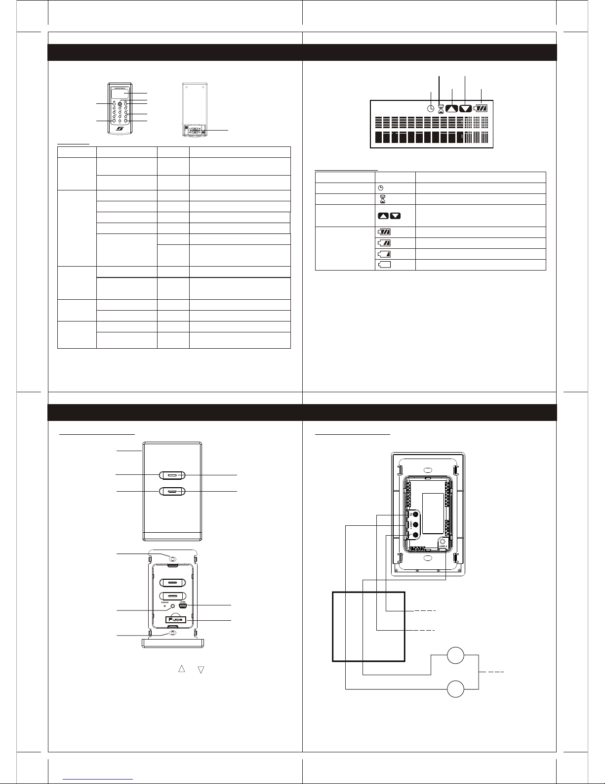
3.UNDERSTANDING OF WIRELESS REMOTE CONTROLLER
Wireless Remote Controller
LCD display
Navigation
Back
Number
All ON All OFF
Yes/ Mood
Battery compartment
AAA x 2 pcs
Alkaline
3.1Buttons
Buttons
Screen Display
Operation
Action
Device Status Page
Press
Switch to Mood Control:
press 1-5 to select mood
Go to next menu
Press
Menu
Yes/Mood
Device Control Page (Gp 1-5 Gp 6-10)
Show system date and time
Go to Menu
Down
Left/Right
Menu
Up/Down
Press
Press
Navigation
Scroll menu items
Go to next menu
Select current menu items
Number
Device Status Page
Menu
Press
Control a ON/OFF of device in group
Enter dimmer Level control page
when all the device in group
are dimmer
All OFF
Device Status Page
Edit Name
Press
Press
Turn OFF all the devices
change case
Device Status Page
Device Status Page
Device Status Page
Press
Cancel current control process
Device Status Page
Up
All ON
Device Status Page
Edit Name
Press
Press
Turn ON all the devices
Backspace
3.2 LCD Display Icons
System Clock Not Set
Operation of navigation button up and down is
enabled
(Flashing)
Icon
Display
Indication
The system clock is not set
Processing request, busy
Battery full
Battery half
Battery Low
Need to replace battery immediately
Key Up Enable/
Key Down Enable
Processing
Battery Level
3.UNDERSTANDING OF WIRELESS REMOTE CONTROLLER
4.UNDERSTANDING OF THE DEVICES
4.1 Two Gang Light switch
Remarks :1. For one gang light switch , same as above but only have button 1.
2.For dimmer, same as above but and are printed on the cover, to
indicate up and down function of the dimmer buttons
Cover
On/Off button 1
On/Off button 2
LED indicator
LED indicator
Fuse
Connector for initial setup
Refer to Section 5
Reset button
Screw holes
Screw holes
Wall Box
Neutral
Live
Light 2
Light 1
Neutral
Load 2
Load 1
Wiring Diagram
Remarks : for one gang light switch and Dimmer, same as above but only one load can
be connected
4.UNDERSTANDING OF THE DEVICES
4.1 Two Gang Light switch
RESET
CO-ORDINATOR

R
E
SE
T
CO-ORDINATOR
4.UNDERSTANDING OF THE DEVICES
4.2 AC socket
Screw holes
On/Off button
LED indicator
Cover
Connector for initial setup
Refer to Section 5
Reset button
Fuse
1312
15
14
4.UNDERSTANDING OF THE DEVICES
Wiring Diagram
Wall box
Earth
Neutral
Live
Live
N
eu
t
r
al
E
ar
t
h
5. INSTALLATION
Coordinator : It is recommended to be installed at the center of the whole system.
Other device: During installation, user shall check the signal coverage of the location for
installation
5.1 INSTALLATION METHOD
a) .Always turn off the power source at the Miniature Circuit Breaker
( MCB) before installation, maintenance or servicing of light fittings
b) .Loosen the screws of the original wall switch, remove the switch and disassemble the
wiring.
C) .Connect the main power cable to the Live and Neutral terminals at the rear cabinet of the
devices. Then connect the load cable to the Load terminals
One gang, Two gang light switch
Or dimmer
AC socket
d) . Fasten the screws of all terminals and check that the wires are properly secured
e) . Retrofit the switch into the standard switch box and mount it on the wall by fastening the
two screws at the rear of the switch box
f) . Pre-program the system according to the procedures indicated in section 6 to 11
g) . Clip the Cover Plate of the switch , Dimmer or AC socket back in place
5. INSTALLATION
Remarks: in the following sections, you will be required to connect the provided cable
to connect to the USB shape connector of the light switch or AC socket or Dimmer.
Please use a screw driver to open the connector cover. The following diagram is for
CG100S2, do the same for CG100C, CG100S1, CG100DM.
* Please Refer To Appendix 12.4 For The Wire Specification *
Sk
RESET
R
E
S
E
T
R
E
S
E
T
CO-ORDINATOR
CO-ORDINATOR
R
E
S
E
T
CO-ORDINATOR
R
E
S
E
T
CO-ORDINATOR
RESET
CO-ORDINATOR
1716
1918
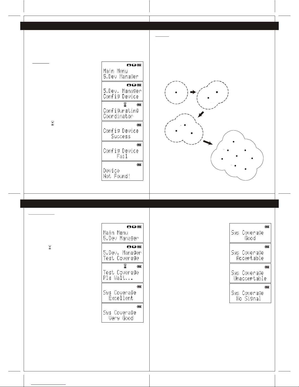
6. Device Configuration
This section provides information for user to link up their CG100 devices to form a
wireless network. The device configuration is fundamental process for wireless control of
each CG100 device. User is required to configure the Coordinator (CG100C) primarily
before configurating the other CG100 devices. Also, the system allows only ONE Coordinator
(CG100C) is configured in the network. The procedures to configure the coordinator and the
other CG100 devices are illustrated in following sections.
6.1 Coordinator
To configure the coordinator, perform the following
steps.
1 -Power up the Coordinator (CG100C) and Wireless
remote controller(CG100R).
2 -Connect the Wireless remote controller to the
Coordinator through the provided cable.
3 -Press the "Navigation" button of the Wireless
remote controller to enter Menu, and then scroll to
"Dev. Manager" of the Menu.
4 -Press "Yes" button to enter "Dev. Manager" Menu,
and then scroll to find "Config Device".
(Note: All the device in system need to re-configure
if the Coordinator is configured)
5 -Press "Yes" button to configure the Coordinator.
(Note: The icon is indicating that Wireless remote
controller is configuring the Coordinator)
(Note: The process to configure coordinator may
take a minute)
6 -When the coordinator is configured successfully,
the Wireless remote controller will show "Success".
During the configuration of Coordinator, if "Fail" or
"Device Not Found" is shown on the display,
please check the power of the Coordinator and the
connection between the Coordinator and Wireless
remote controller. Then perform step 1 to step 5 again.
6. Device Configuration
6.2 Device
When the Coordinator (CG100C) is configured successfully, user may configure other CG100
devices to establish network connection with the Coordinator. To achieve the best system
performance, user is strongly advised to test the system coverage of the location that is
planned to install the CG100 devices. On the other hand, when a CG100 device is configured
successfully, the system coverage will be increased by the newly added CG100 device
(Figure 6-1).
Therefore, user is strongly recommended to install and configure the CG100 devices which
are close to the Coordinator firstly for extending the system coverage for other CG100
devices which are far from the Coordinator. The procedures to test the system coverage and
to configure the CG100 devices are illustrated in Section 6.2.1 and Section 6.2.2.
Coord inator
Syst em
Cove rage
Coordi nator
System
Covera ge
New
Device
Coord inator
System
Coverage
Device
New
Device
Coordin ator
System
Coverag e
Device
New
Device
New
Device
New
Device
New
Device
New
Device
New
Device
Figure 6-1 newly added device will extend the coverage of system.
6. Device Configuration 6. Device Configuration
6.2.1 Test Converge
To test the system coverage before configurating a new device, perform following steps
1 -Place the Wireless remote controller (which is used to
configure the Coordinator before) to the location
which is planned to install the new device.
2 -Press the "Navigation" button to enter Menu, select
"Dev. Manager", and then go to "Test Coverage"
and press "Yes".
(Note: The icon is indicating the Wireless remote
controller is testing the network coverage.)
3 -After several second, the testing result will show
on the screen.
If the result is either Excellent, Very Good, Good or
Acceptable, user can install the new device to the
tested location. Otherwise, user may need to change
the installation location
After finding a correct location for device installation, user may install the new
CG100 device to such location and prepare to configure the new device.
Coordinator
System
Coverage
New
Device
Coordinator
System
Coverage
Device
Coordinator
New
Device
System
Coverage
New
Device
New
Device
New
Device
New
Device
New
Device
New
Device
Device
Coordinator
 Loading...