

Page 1

Cryptoworks Embedded Free To Air / Common Interface
Digital Satellite Receiver
CCR 521 / CCR 525
User’s
Manual
Page 2

1. SAFETY PRECAUTIONS
2. GENERAL FEATURES
3. HOW TO CONNECT YOUR RECEIVER
4. HARDWARE DESCRIPTION
5. SYSTEM SET-UP
6. MENU OPERATION
7. UPGRADE BY SATELLITE
8. TROUBLE SHOOTING
9. TECHNICAL SPECIFICATIONS
2
3
4
6
10
12
24
26
27
Table of Contents
Table of Contents
Page 3
GENERAL FEATURES 3
SAFETY PRECAUTIONS 2
This receiver has been manufactured to satisfy the international
safety standards.
Please read the following recommended safety precautions carefully
MAINS SUPPLY : 90240V AC 50/60Hz
LOCATION : Locate the receiver indoor.
Locate receiver away from potential hazards such as houseplants, lighting, raining and direct sunlight.
OVERLOADING : Do not overload wall outlets, extension cords or adapters as this
can result in fire or electrical shock.
LIQUIDS : Keep liquids away from the receiver.
CLEANING : Before cleaning, disconnect the receiver from the wall socket.
Use a cloth lightly dampened with water (no solvents) to clean the exterior.
VENTILATION : Do not block the receiver ventilation holes. Ensure that free airflow is
maintained around the receiver.
Never set the receiver on soft furnishings or carpets. Do not use or store the receiver
where it is exposed to direct sunlight, or near heater.
Never stack other electronic equipment on top of the receiver.
Place the receiver at least 30mm from the wall.
ATTACHMENTS : Do not use any attachment that is not recommended by the manufacturer,
as it may cause a hazard or damage the equipment.
CONNECTION TO THE SATELLITE DISH LNB : The LNB connector cable has a
voltage in its center core. It is therefore recommended that the receiver is disconnected from
the mains power before connecting or disconnecting this cable.
FAILURE TO DO SO COULD DAMAGE THE LNB.
SERVICING : Do not attempt to service this product yourself. Any attempt to do so will
make the warranty invalid.Refer all servicing to a qualified service agent.
LIGHTNING : If the receiver is installed in an area subject to intense lighting activity,
protection devices for the receiver mains connector and modem telephone line are essential.
The individual manufacturer
s instruction for safeguarding other equipment, such as TV set,
Hi-Fi, etc., connected to the receiver, must also be followed during lighting storms.
GROUNDING : The ground of the LNB cable must be directly connected to the system
ground for the satellite dish. The grounding system must comply with local regulations.
1. SAFETY PRECAUTIONS
- Fully MPEG-2 & DVB Compliant
- Smart card interface for the embedded CryptoWorks
- 2 Slots of Common Interface for Viaccess, Conax, Cryptoworks,
Nagravision, Irdeto, SECA
- Input Frequency 950
2150MHz
- Supports SCPC & MCPC from C / Ku-band
- 1 LNB Input Tuner with Loop Through IF Signal
- Tuner Symbol Rate : 1
45MS/s
- Fast Booting & Auto Scan
- Quick Channel Changing
- Max. 4000 Channels(TV & Radio) Programmable
- User Friendly 256 Colors OSD & Easy GUI
- A lot of OSD Language supported
- Supports EPG, PIG
- Radio Channel Background Display
- Favorite Channel List Programmable
- Master PIN Code Function & Parental Lock Function
- 40 Steps Volume Control
- Automatic Detection of Forward Error Correction
- Automatic NTSC / PAL Detection and Simple Video Converter (NTSC <-> PAL)
- Window based S/W Download Program Supported by RS232 Serial Port
- Set to Set Download (Main Program, Channel Data)
- 4:3, 16:9 Letter Box & Teletext using OSD
- 7 Segment-4 Digit Display
- 5 Keys on the Front Panel (Power On/Off, Channel Up/Down, Volume Up/Down)
- Various LNB Polarity Control
�DiSEqc 1.0 & 1.2 with 500mA Max. LNB Power
�22KHz Switching Control
- 2 SCART Output for TV & VCR
- 3 RCA Output for Video, Audio L/R
- Wide PLL RF Modulator (PAL B/G, I, D/K)
2. GENERAL FEATURES
Page 4
HOW TO CONNECT YOUR RECEIVER
5
HOW TO CONNECT YOUR RECEIVER
4
Please DO NOT plug in the main power supply cord until
you have finished all the connections.
1) LOCATION OF THE RECEIVER
Your receiver should be placed under proper ventilation.
Don
t put in completely enclosed cabinet that will restrict the flow of air, Resulting overheating.
The location should be safeguarded from direct sunlight, excess moisture,
rough handling or household pets.
Avoid stacking other electronic components on the top of the receiver.
The location should be safely accessible by the cable from your antenna system.
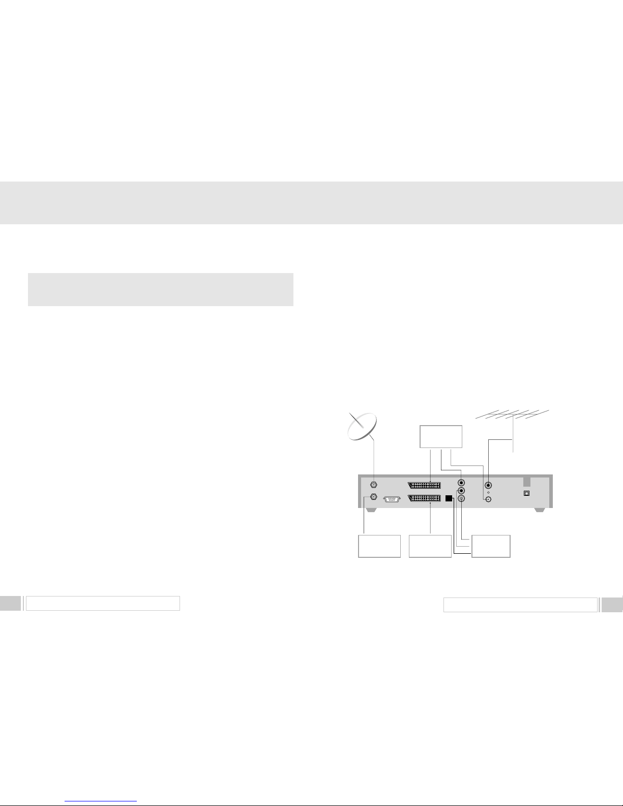
2) CONNECTING THE RECEIVER WITH DISH SYSTEM
After installing your dish system, connect the coaxial cable from LNB of your dish antenna to
LNB INterminal marked at the rear of the receiver.
All cable connectors should be finger tightened ; do not use any kind of wrench
on the cable over connectors.
The cable should be 75
Ϊ impedence coaxial twisted at the end with a Ftype connector.
3) CONNECTING THE RECEIVER TO TV
To connect the receiver with your television, you can follow two methods ;
through RF cable, and through SCART cable.
Connect the RF cable to the terminal marked
TV OUTat the rear panel of the
receiver and its other end to the TV RF input socket.
In the case of connecting your TV through SCART cable, connect the SCART connector
marked TV to respective SCART port in the TV.
4) CONNECTING YOUR VCR
To connect a VCR, the receiver has been provided with SCART at the rear
marked
VCR. Using a SCART connector, the VCR can be connected to the receiver
3. HOW TO CONNECT YOUR RECEIVER
Analog
SVR
LNB IN
IF OUT
SERIAL PORT
VCR
TV
R
VIDEO
AUDIO L
SPDIF
TV OUT
ANT IN
Hi-Fi
Stereo Audio
TV
Antenna
Satellite
Antenna
TV
VCR
5) CONNECTING EXTERNAL AUDIO HI-FI SYSTEM
To connect any external Audio Hi-Fi system, the receiver has been provided with two
RCA connectors at the back of the receiver, marked with Audio L and R respectively to
connect the left and right Audio.
6) CONNECTING YOUR ANALOG RECEIVER
To facilitate the user using analog receiver to view analog channels,
the receiver has been provided with a loop through terminal marked as
IF OUT.
Connect the coaxial cable from this terminal to the
IF input terminal of your analog receiver.
Now by keeping the receiver in standby,
you will be able to tune and view analog channels from your analog receiver.
Page 5
HARDWARE DESCRIPTION 7
HARDWARE DESCRIPTION6
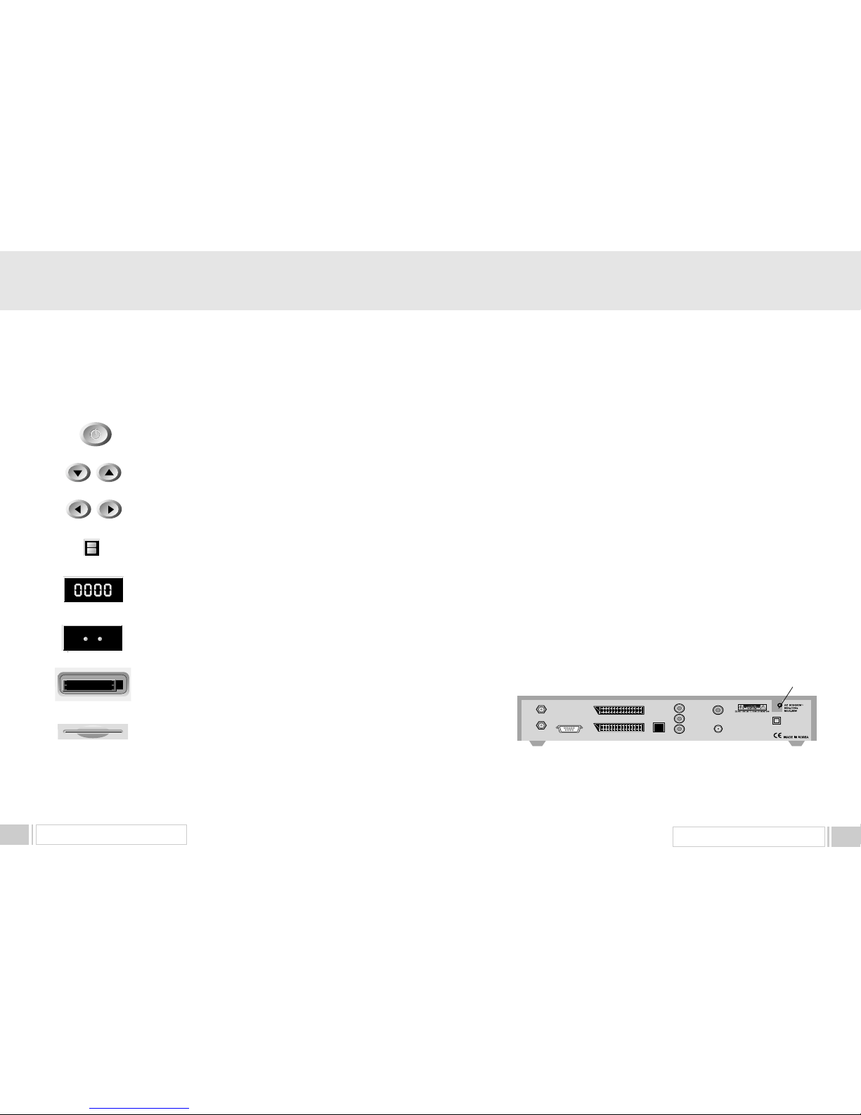
1) POWER : This key is used to turn the receiver on and off (stand by).
2) CH : These keys are used to change the channels.
3) VOL : These keys are used to increase and decrease the volume
level manually.
4) INFRARED SENSOR : This is to receive the IR commands from the
RCU. Do not block the view of the sensor.
5) 7 SEGMENT DISPLAY : This SEGMENT display will show the current
channel number.While the receiver is in stand by mode, the display will show
the current time.
7) CI CAMSLOTS : 2 Slots for Common Interface CAM (VIACCESS,
IRDETO, NAGRAVISION, CRYPTOWORKS, CONAX, SECA) with smart
card.(Option for CI model only)
POWER
C H
VOL
INFRARED SENSOR
7 SEGMENT DISPLAY
CI CAM SLOTS
6) LED DISPLAY: This LED display will show the current power mode status.
If receiver is in stand by mode,stand by mode LED will be on. and when
receiver is in on mode, on mode LED will be on.
(Option for LED display model only)
LED DISPLAY
STANDBY ON
8) SMART CARD INTERFACESLOTS : To watch scrambled
channels you should insert a smart card into Smart Card Interface issued the
service provider whom you subscribes to. Therefore you can watch only a
specific range of channels with entitlements in smart card. The smart card
includes information to decipher parameters necessary for descrambling the
program. Please note that the gold chip on the smart card should face
download and inward when you insert when you insert it into Smart Card
Interface. (Option for CAS model only)
SMART CARD
INTERFACESLOTS
4. A. FRONT PANEL
4. HARDWARE DESCRIPTION
③
②
⑦
⑥
⑧
⑩
⑨
⑤
④
①
LNB IN
IF OUT
SERIAL PORT
VCR
SPDIF
R
TV
VIDEO
AUDIO L
TV OUT
ANT IN
1) LNB IN : This port is to connect the coaxial cable from LNB of your Dish. The IF input is provided through
this port and the input frequency range is 950
2150MHz. Also the voltage switching 13V and 18V is
passed through this port.
2) IF OUT : To enable the connection of an analog receiver, the receiver is provided with this port. Connect
this port to LNB IN port of the other receiver via RF Cable.
3) SERIAL PORT : This is used to connect your receiver with computer through a serial cable.
This port can be used for upgrading software.
4) TV SCART : This is used to connect your TV through SCART.
5) VCR SCART : This is used to connect your VCR.
(When you connect external sets to above two SCART sockets, always use fully featured SCART cables)
6) S/PDIF DIGITAL OUTPUT : This port is for the connection to the external Hifi system which has a optical
S/PDIF input interface.
(Option)
7) VIDEO, AUDIO R/L
: These RCA connectors are used to connect any external video and audio.
8) ANT IN : This is used to connect your local RF channels to your TV through Loop.(Option)
9) TV OUT
: This is used to connect your TV through RF cable.(Option)
10) POWER INPUT
: This is to plug in the AC mains power cord.
The input AC volts range is 90V to 240V, 50Hz/60Hz supply.
4. B. REAR PANEL
Page 6
8
9HARDWARE DESCRIPTION
HARDWARE DESCRIPTION
15) LAST : This key is used to return to the previous channel.
16) AUDIO : This key is used to select the soundtrack list for the current service
and also used to select audio mode.
17) PAUSE : This key is used to pause the screen.
18) NTSC/PAL : This key is used to convert video mode.
19) SAT : This key is used to select the satellite.
20) F1, F2, F3, F4 : Function Keys.
21) TEXT : This key is for Teletext.
4. C. REMOTE CONTROL UNIT
1) POWER : This is used to switch the receiver to ON/STANDBY mode.
2) MUTE : This key is used to toggle between normal and muted audio.
3) 0-9 NUMERIC KEYS : These keys are used to enter numeric values and to
select the channel directly by entering its number.
4) CH
▲∙CH▼: These keys are used to change channels and to browse the menu.
5) VOL
▶∙VOL◀: These keys are used to vary the volume level and to change the
cursor options in the menu.
6) MENU : This key is used to open up the menu.
7) EXIT : This key is used to exit from any menus.
8) OK : This key is used to enter and confirm any data to the receiver in the menu systems.
The Channel list can be accessed directly by pressing this Key
in the normal view mode.
9) Page Up : This key is used to page up the menu.
10) Page Down : This key is used to page down the menu.
11) FAV : This key is used to switch between favorite lists.
12) GUIDE : This key is used to open up the Electronic Program Guide.
13) i : This key is used to view the channel information.
14) : This key is used to toggle between the TV channel and the radio channel.
LAST
AUDIO
PAUS E
NTSC
/ PAL
SAT
F1 F2 F3 F4
TEXT
0 ~9
MENU
EXIT
OK
FAV
GUIDE
i
Page 7
SYSTEM SET-UP 11
SYSTEM SET-UP
10
System Connection
Power On
Antenna Configuration Setting
Automatic Channel Search
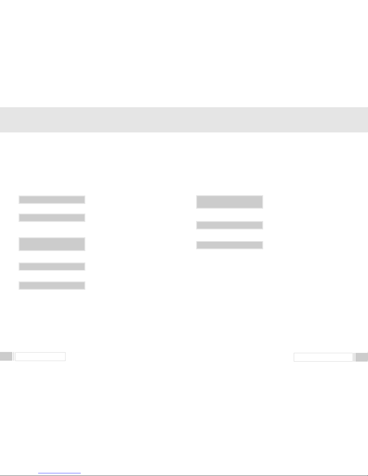
Main Menu / Channel Search
Connect the receiver to all peripheral devices.
Turn on the power of the receiver and other
devices.
Select Main Menu / Channel search using
CH
& OK keys.
Select the satellite which you want to search
using VOL
keys.
Insert all information of your antenna.
Press OK key, and the receiver will automatically
search for all TV/Radio channels from a satellite.
5.A. Automatic channel search for a satellite
You can automatically detect and save all TV and Radio channels
of a satellite as follows :
5.SYSTEM SET-UP
Select Menu / Channel Search.
Select the satellite which you want to search.
Insert all information of your antenna.
Move to the transponder list by pressing “FAV”
key or VOL
keys.
You can move back to the satellite window for
automatic channel search by pressing “FAV” key
or VOL
keys again.
Select the transponder from transponder list
which you want to search.
If you cannot find it from transponder list, you
should insert all the transponder information
(i.e., Frequency, Symbol Rate, Polarity, and FEC).
Press OK key, and the receiver will automatically
search for all channels contained in the selected
transponder.
Antenna Configuration Setting
Manual Channel Search
Main Menu/Channel Search
5. B. Manual channel search for a transponder
You can automatically search and save all TV and Radio channels of
a transponder as follows :
Page 8
MENU OPERATION 13
MENU OPERATION12
The main menu is classified into four sub menus which will carry out the
various operation individually.
MAIN MENU
After installing your dish system and receiver with appropriate connectors, plug in the AC main
power and turn on the receiver.
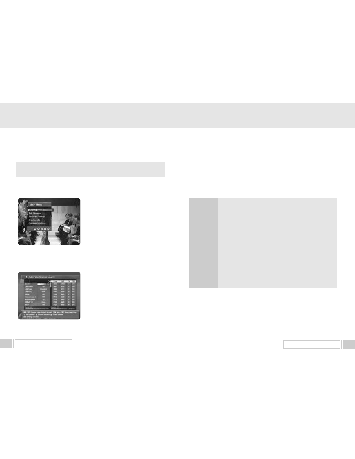
Press the MENU key of the RCU. You will see the Main
Menu
on the TV screen as follow.
Please note that the
Common Interface menu will be
displayed for the CI Model.
You can move into the desired submenu using the
up / downkeys() or nemeric keys.
Press
OKkey to confirm your selection. If the Main
Menu
is locked, note that you should enter the PIN
code in order to move into each submenu. The default
factory PIN code is
0000.
Press the
menu key or exit key to return to
previous menu.
1. Channel Search
This menu helps you to add or delete satellites and transponders, setup various parameters to
receive signal and search channels currently available.
Select “ Channel Search ” item in the main menu, and
you will be asked to enter your PIN code. You can find
the following “ Channel Search ” screen when you enter
the correct PIN code.
You can move selection from the satellite window
(Automatic search mode) to the transponder window
(Manual search mode) by pressing “ left / right ” key
(
at the satellite name or by pressing “ FAV ” at
any position. You can move back to the satellite window
by pressing “ left / right” key (
or “ FAV” key at any position in the transponder window.
1.A. AUTOMATIC CHANNEL SEARCH
When you are in the satellite window (left side of this screen), you can add, delete or edit satellite
information and also scan all the transponders of the selected satellite to find the channels.
Select the desired satellite using the “SAT” key.
Set
LNB Power , LNB Type , LNB Freq , 22KHz ”, “ Network Search ” Search
Option
, and DiSEqC Type fields to the appropriate value using the “ left / right ” keys()
at each field.
6. MENU OPERATION
LNB Power
LNB Type
LNB Freq.
22KHz
Nework Search
Search option
DiSEqC Type
Depending on the users antenna LNB, you can supply either LNB
power by setting
ONor not by setting OFF. Normally set this to
ON.
You can select the LNB type.
You can select the predefined LNB frequency or manually enter a
specificfrequency in MHz unit by pressing numeric keys.
In case you are using two antennas connected to a 22KHz tone switch
box, you can supply either 22KHz by setting
ONor off by setting
OFFto select antenna.
You can search the additional channels indicated form service provider
if exist.
You can search all the free channels & scramble channels or only free
channels or onlyscramble channels by setting the search option.
If you have DiSEqC box, you can choose port by selecting port number.
Otherwise, choose
none. If you have a DiSEqC 1.2 motorised system,
then you can take advantage of the DiSEqC 1.2 functions available.
Choose “Motor” as DiSEqC type and press “F4” key.
After that, adjust antenna direction using browse keys.
Check the signal strength. Press
OKkey to start the Automatic Channel Searchprocedure.
You can see the progressive status of channel searching.
Please note that the
Automatic Channel Searchprocedure may take a few minutes.
Press the
menukey or exitkey to return to previous menu.
Page 9
MENU OPERATION 15
MENU OPERATION14
1.B. MANUAL CHANNEL SEARCH
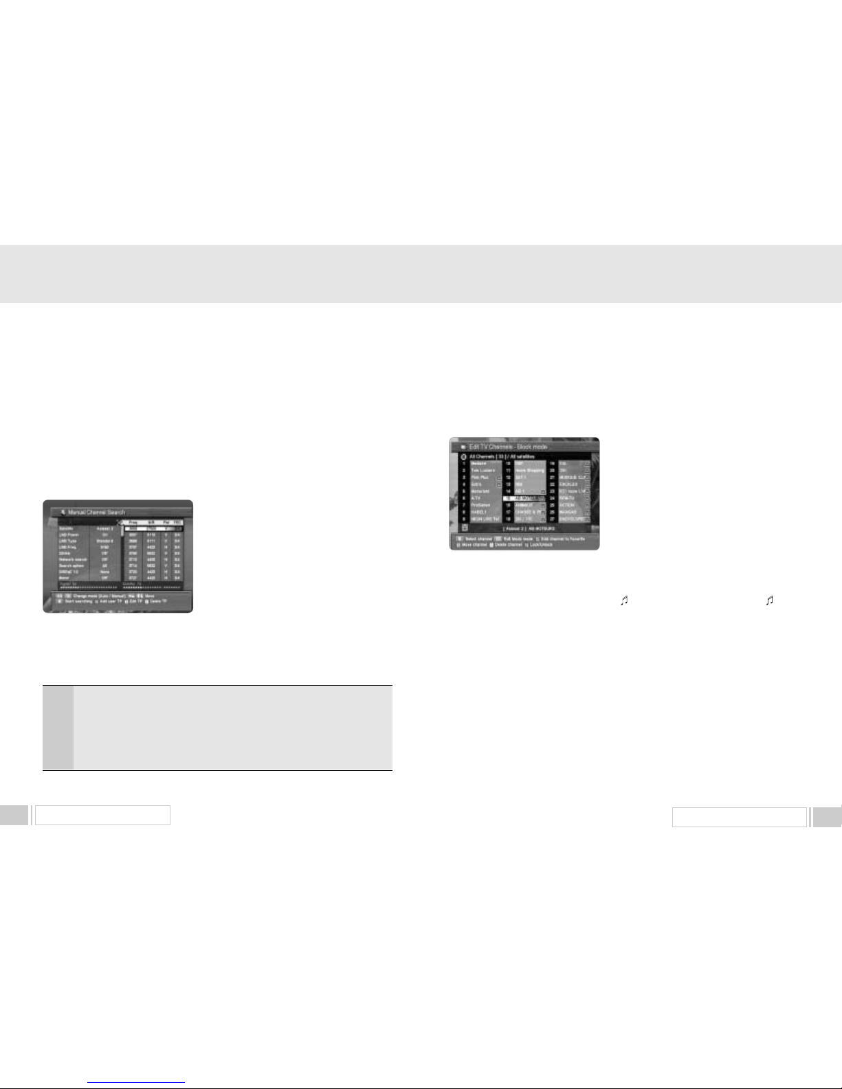
When you are in the transponder window (right side of this screen), you can add, delete or edit
transponder information and also scan the selected transponder to find the channels. Select the
transponder using “up/down” keys or “page up/down” keys and press “OK” key to start
search for the selected transponder. You can also
monitor the status of searching process.
When you want the other satellite than current one,
move to the satellite window and change it to new one.
You can move between the satellite window and the
transponder window by pressing “FAV” key“or
“ left / right” keys (
If you cannot find the desired transponder from the
transponder list, you can add new one by pressing
“ F1” key and entering appropriate parameters for this
transponder. When you want to modify the parameters
of an existent transponder, select the transponder and
enter into the edit mode by pressing “F2” key. After change all the necessary parameters, press
“Exit” key to escape from the edit mode. You can also delete unwanted transponders by pressing
“F3” key.
Each parameter has following meanings.
2. Edit Channels
You can edit channels, group them into the favorite list and also change the properties of each
channel on various channel lists from this menu.
Select “ Edit Channels ” item in the main menu, and you will be asked to enter your PIN code.
You can find the following “ Edit Channels ” screen
when you enter the correct PIN code.
There are two modes in editing the channels – normal
mode and block mode.
In normal mode, you can edit each channel
separately. You can add to the selected channel into
the favorite list. And you can also delete, lock/unlock or
rename each channel. In block mode, you can edit
multiple channels at a time. You can select multiple
channels and add them to the favorite list.
You can also delete, move or lock/unlock them at a time. To select block, move to a channel and
press “ OK ” key and move to another channel and press “ OK ” key, so on.
When you want to exit block mode, press “Exit” key to return to the normal mode.
You can change the list you want to edit using “” key and “FAV” key. When you press “” key,
the current list is changed between TV channel list and Radio channel list. When you press “ FAV ”
key, the current list is changed as follows: All channels -> FTA channels -> Scrambled channels ->
Favorite 1~8 channels.
2.A. Add to favorite list – F1 key
Select channel that you want to add to the favorite list using the “up/down” keys and the “ page up /
down ” keys. When you want to add multiple channels into the same favorite list, set those channels
as block by pressing “ OK ” key at each channel. You can also deselect each selected channel by
pressing “ OK ” key again. After select channel or set block, press “F1” key to invoke “Add To
Favorites” window. Select favorite list you want from the window.
Please note that you can not invoke “Add To Favorites” window when the current channel list is the
favorite list.
You can also sort the channel list by pressing “ i ” key.
Freq.
S/R
PoI.
FEC
Input the frequency of the transponder you want to find manually.
Input the symbol rate of the transponder you want to find.
Select the polarization of the transponder you want to find. In the case of
horizontal,
18V and in the case vertical, 13V are output through LNB line.
Select the FEC of the transponder you want to find. You can select the value of
1/2, 2/3, 3/4, 5/6, 7/8 or auto.
If you cannot find the desired satellite from the satellite list, you can add new one by pressing “F1”
key and entering appropriate parameters for this satellite. The default name of the added satellite is
“UserSAT-No.” When you want to change the name of the current satellite, press “F2” key and
enter new name. You can also delete unwanted satellites by pressing “F3” key after select it.
Page 10
MENU OPERATION 17
MENU OPERATION16
2.B. Edit channel name – F2 key in normal mode
Select channel that you want to rename using the “ up / down ” keys and the “ page up / down ”
keys. Press “ F2 ” key to invoke the keypad window and enter new name from the window. In block
mode, you cannot edit channel name as multiple channels are selected. Please note that you can
edit not a channel name but a channel list name when the current channel list is the favorite list.
2.C. Delete channel – F3 key
Select channel that you want to delete using the “ up / down ” keys and the “ page up/ down ” keys.
When you want to delete multiple channels at a time, set channels as block by pressing “OK” key at
each channel. You can also deselect each selected channel by pressing “OK” key again. After
select channel or set block, press “F3” key to delete the selected channel(s).
2.D. Lock/Unlock channel – F4 key
Select channel that you want to lock or unlock using the “ up / down ” keys and the “ page up / down
” keys. When you want to lock or unlock multiple channels at a time, set channels as block by
pressing “OK” key at the each channel. You can also deselect each selected channel by pressing
“OK” key again. After select channel or set block, press “F4” key to lock or unlock the selected
channel(s).
2.E. Move channel – F2 key in block mode.
You can change the position of channels in the channel list by selecting them as a block and move
them. Select channel(s) you want to move using the “ up / down ” keys and the “ page up / down ”
keys and press “OK” key. After set block, press “F2” to enter block move mode. You can move
selected block of channels by using “ up / down ”, “ left / right ” or “ page up / down ” keys in the
channel list. After move to the new position, press “OK” key to locate those channels at this position.
Select video output mode - CVBS or RGB
Select or change RF channel number when your receiver is
connected to TV by RF connector. The factory preset value is
channel 38.
In the above case, you can choose PAL B/G mode or PAL I mode
or PAL D/K mode.
You can choose either 4:3 or 16:9 according to the TV type.
You can select the transparency of the menu.
Adjust the clock.
You can select the menu language.
You can select the audio language.
You can choose the OSD color.
You can set how long the information box will be displayed.
TV Select
RF Channel
RF Mode
Screen Type
Menu Transparency
Time Adjustment
Menu Language
Audio Language
OSD Color
Information Timeout
Press the menukey or exitkey to return to previous menu.
3. Receiver Settings
You can change the various settings of your receiver in this menu.
3.A.System Settings
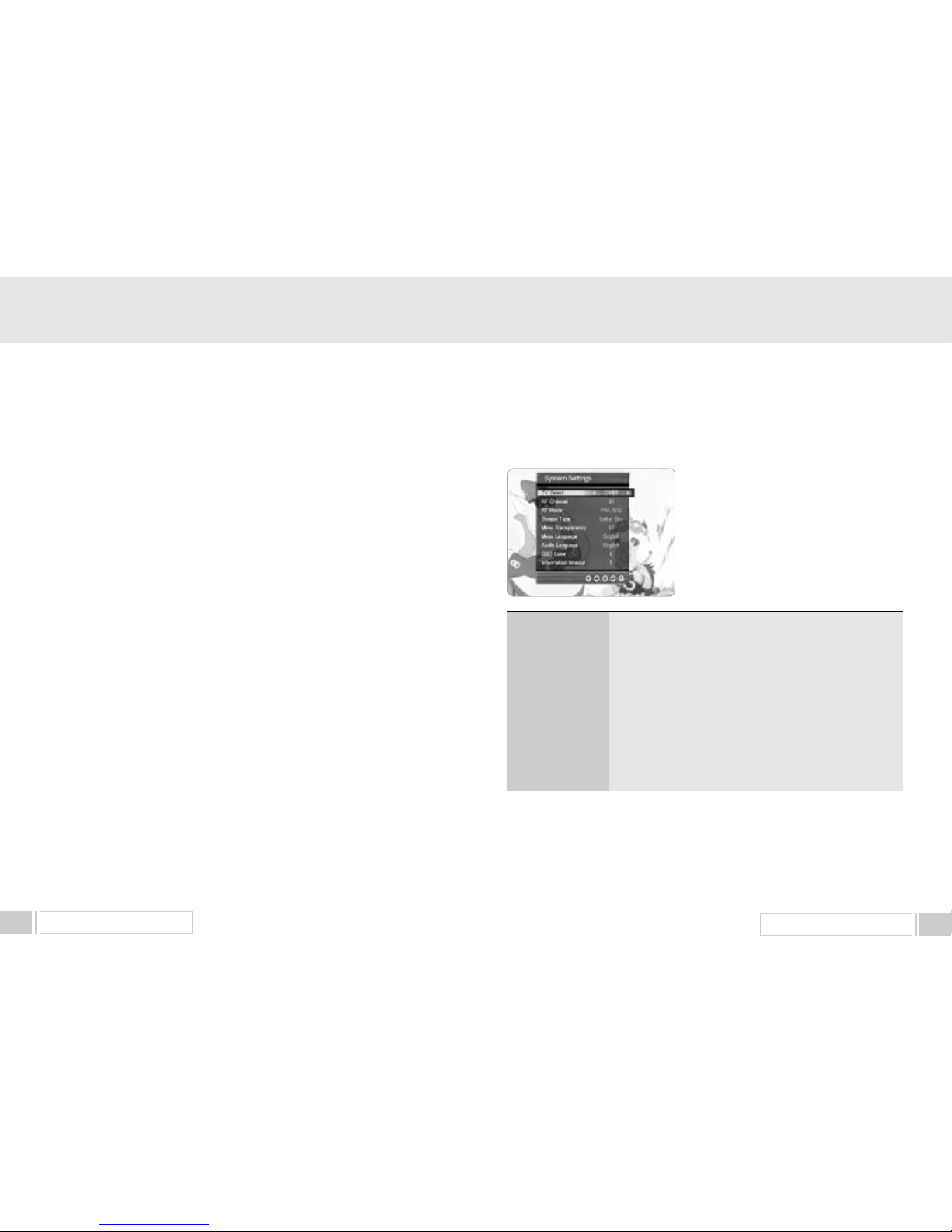
This menu helps you to Set up video output mode,
Ianguage, time, screen type and parameters related
with RF modulator.
Select
System Settingsmenu in the “Receiver
Setting”Menu, and the following screen will be displayed.
Page 11
MENU OPERATION 19
MENU OPERATION18
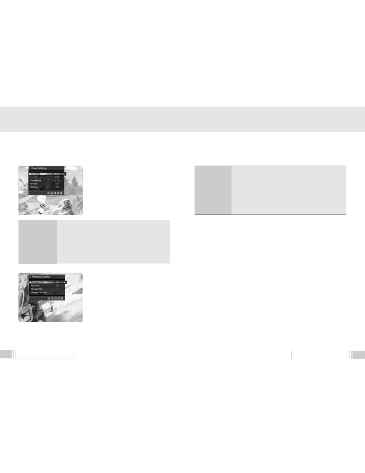
3. C.Parental Controls
This function prevents children or unauthorized
persons from watching programs.
Also you can change PIN(Personal Identification
Number) code.
Select Parental Controlmenu in theReceiver
Settings
menu, and the following screen will be
displayed.
Lock or unlock your receiver. When receiver is locked, the PIN code will
be required whenever you turn on the receiver.
Lock or unlock the menu of your receiver. When menu is locked, the PIN
code will be required whenever you enter the menu items.
Set the level of maturity rate that the receiver will show the channels
without asking PIN code.
You can change your PIN code from the previous one in this menu. If
you forget the PIN code, you have to contact the distributor to find out it.
The factory default is “0000”.
Receiver lock
Menu lock
Maturity Rate
Change PIN code
Select the time mode of your receiver. In Auto mode, your receiver
will use the information from the satellite as timereference. In
manual mode, you can set the time of your receiver manually.
Set the time offset from the reference time.
Useful in auto mode only.
Set the current time manually. Useful in manual mode only.
Set the time when the receiver will be automatically turned on
Set the time when the receiver will be automatically turned off.
Time Mode
Time Adjustment
Current time
On time
Off time
3.B. Time Settings
You can change the time of your receiver and also
switch on/off the timer function in this menu.
Select “Time Settings” item in the “ Receiver Settings”
menu and the following screen will be displayed.
3. D. RECEIVER UPGRADE
You can upgrade the software of this receiver through serial port when the new software is
released.
Please contact the distributor for receiver upgrade.
Distributor supports you useful information and new software for the receiver.
3. E. FACTORY DEFAULT
This is to restore the factory set values in case the user has encountered some problems
after changing any new values of channel data and others which may be in error.
Select Factory Defaultmenu in the “ Receiver Settingsmenu and press OKkey.
If you want to continue, select
Yescell.
The receiver will be reset to settings automatically.
Please note that the
Factory Defaultprocedure may take a few minutes.
4. CryptoWorks
You can find the information about your CryptoWorks smart card, the list of program providers and
your subscription status from this menu. You can also control PIN code for your smart card or
modify maturity ratings for the scrambled channels.
Page 12
MENU OPERATION 21
MENU OPERATION20
When you press “ i ” key again, the event description box will be displayed if the current channel
includes EPG information.
Otherwise the information box will be closed. Press “ Exit ” key to close the information box or the
event description box.
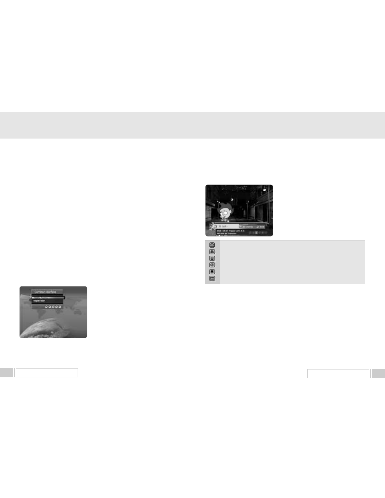
5. COMMON INTERFACE
This receiver is equipped with two PCMCIA slots.
Select
Common Interfacemenu in main menu, and
the following screen will be displayed.
When a common Interface CAM is inserted inside the
PCMCIA slot, the receiver detects the type of the CAM
automatically and display in the main menu.
On choosing this menu, you will be able to access the
different options available with the type of the
CAM like authorizations, prebooking, package details
etc.
4.A General Card Information
This menu displays the label of the card and the list of all available program providers. You can find
the address, validity date and current maturity rating of the smart card from ‘Smart Card Details’
menu.
4.B Available Entitlements
This menu displays the list of all available program providers. You can view the information of the
available entitlements when selecting each program provider. There are three types of entitlementsSubscriptions, PPV events and IPPV events.
4.C Smart Card Managements
This menu allows you to modify the current maturity rating and enable, disable or modify PIN code.
[NOTE] This PIN code is assigned to the smart card by service provider and it is different with the
PIN code in the “Parental Control” menu in “Receiver settings.” The former is for the smart card
and CryptoWorks channel. The latter is for the receiver lock or channel lock functions. So two PIN
code may have different values.
This event is scrambled.
This channel is locked.
This event includes the teletext.
This event includes the multiple audio tracks.
This event includes the subtitle.
This event includes the dolby digital sound track.
MAIN FUNCTIONS
1. Information Box
The information box will pop up when you press “i” key
or change the channel. This box shows the information
about the current channel such as the channel number,
the channel name, the current channel list, the current
time, the signal status, the event description and the
various status of current event.
The status of current event is described with the icons
as follows:
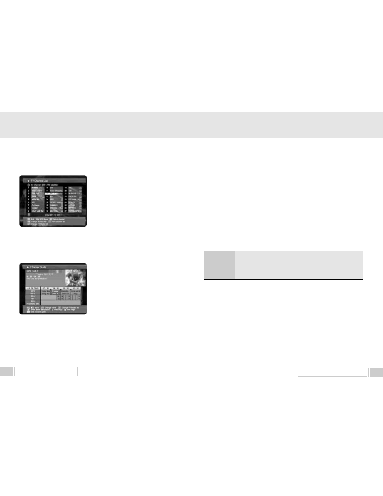
2. CHANNEL LIST
This menu helps you to easily select the channel that you want to watch.
The channel list is separately constructed for each satellite. Press
OKkey, and the following
screen will be displayed. You can get the information of channel number, channel name, and
whether the program is scrambled or locked.
Page 13
UPGRADE BY SATELLITE 23
To watch a specific channel, first select it by pressing
the
up / down keys left / right ” keys
(
and the page up/downkeys ( , ). Then,
press
OKkey.
This enables you to move into that specific channel.
You can also select a specific satellite using the SAT
key. When you press the♬key, you can
alternatively
select TV or radio channel list. When you press
FAV
key, you can see all channel list or FTA channel or favorite channel list.
Press the
menukey or exitkey to return to previous menu.
3. CHANNEL GUIDE
Press GUIDEkey, and the following screen will be
displayed.It will give the titles of the current and next
programmes on different channels.
The information may include : current time / channel
name, name of the current and next programme, the
start and total time of the current programme, the start
and total time of the next programme.
Programme information will be available only when it is
included in the transmission.
When you press the
♬key, you can alternatively select TV or radio channel guide.
Press the GUIDEkey again to view the one channel Guide.
Press the
menukey or exitkey to return to previous menu.
4. Teletext
Your receiver supports the teletext function in two ways. The first method is to draw the teletext
information by itself using the OSD function. The second method is to make your TV set draw the
teletext screen by sending it the appropriate information mixed with the video signal. Your TV set
must have the capability to decode the teletext information for the second case.
When the current channel that you are watching includes the teletext information, you can popup
the teletext screen by pressing “TEXT” key. If this channel also includes the subtitle, the menu for
selecting the teletext or the subtitle will be appeared.
In the teletext screen, you can enter the page number directly by the number keys.
Also you can increase the page number by one using “channel up” key or decrease by one using
“channel down” key.
Function keys are also useful when you are navigating through the pages.
Press “F1” key to go back to the previous page.
Press “F2” key to go the default page. The default page number is “100.”
Press “F3” key to increase the page number by 100.
Press “F4” key to increase the page number by 10.
Press “Exit” key to close the teletext screen
When you do not invoke the teletext screen by pressing “TEXT” key, your receiver will send the
teletext information to the TV set automatically. Use the RCU of your TV set to watch the teletext in
this case.
MENU OPERATION22
▲
▲
▲
▲
Page 14
UPGRADE BY SATELLITE 25
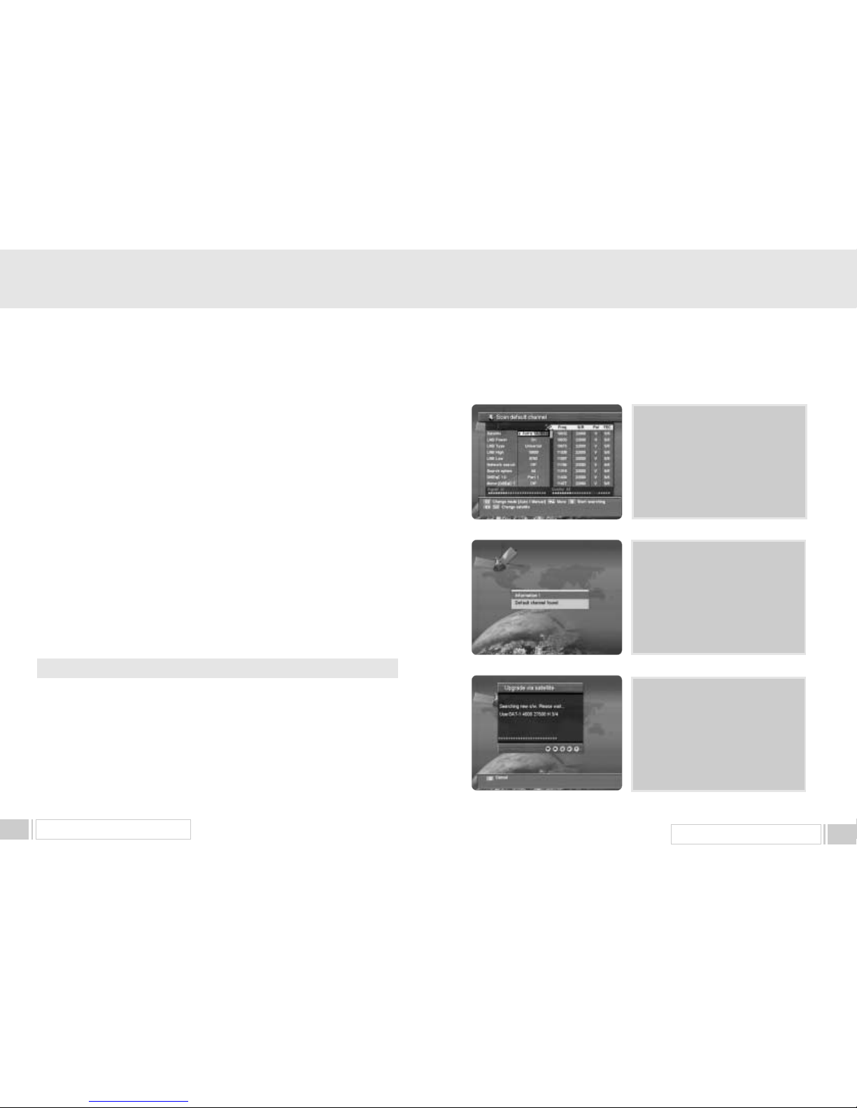
1.A. The default satellite and transponder will
be automatically selected for download.
Please check if LNB and DiSEqC
settings are correct and press “ OK ”
button to find new software.
1.B. If the default channel found, the
following message appears. Otherwise,
go to step 1.A.
1.C. Then the receiver automatically scans
new software. It takes about maximum
5 minutes.
7. UPGRADE BY SATELLITE
Do not switch off the Receiver during the data download!
You can upgrade your receiver up to date, when the new software is available.
When new software is available, it is informed to you by message box immediately or at next power
on. You can ignore it and go on watching program, but it will be notified again when you power off
and on again.
You can also upgrade later by selecting upgrade menu item as follows.
Select “Receiver upgrade” in the “Receiver Settings” Menu to enter Software download.
1. Select “Upgrade via satellite” item and the “ Scan default channel” window will appear as follows.
UPGRADE BY SATELLITE 24
5. Subtitle
When the current channel that you are watching includes the subtitle, you can popup the subtitle
window by pressing “TEXT” key.
When you press “TEXT” key, the menu for selecting the language will be appeared. Please select
the language of the subtitle that you want to watch.
Press “Exit” key to stop displaying the subtitle.
6. AUDIO
Press AUDIOkey.
Select the audio mode which you want using the
left / rightkeys
Some programs are broadcasted with one or more alternative language soundtracks.
You can select the preferred audio language for soundtrack using the
up/downkeys
Page 15
TROUBLE SHOOTING 27
UPGRADE BY SATELLITE 26
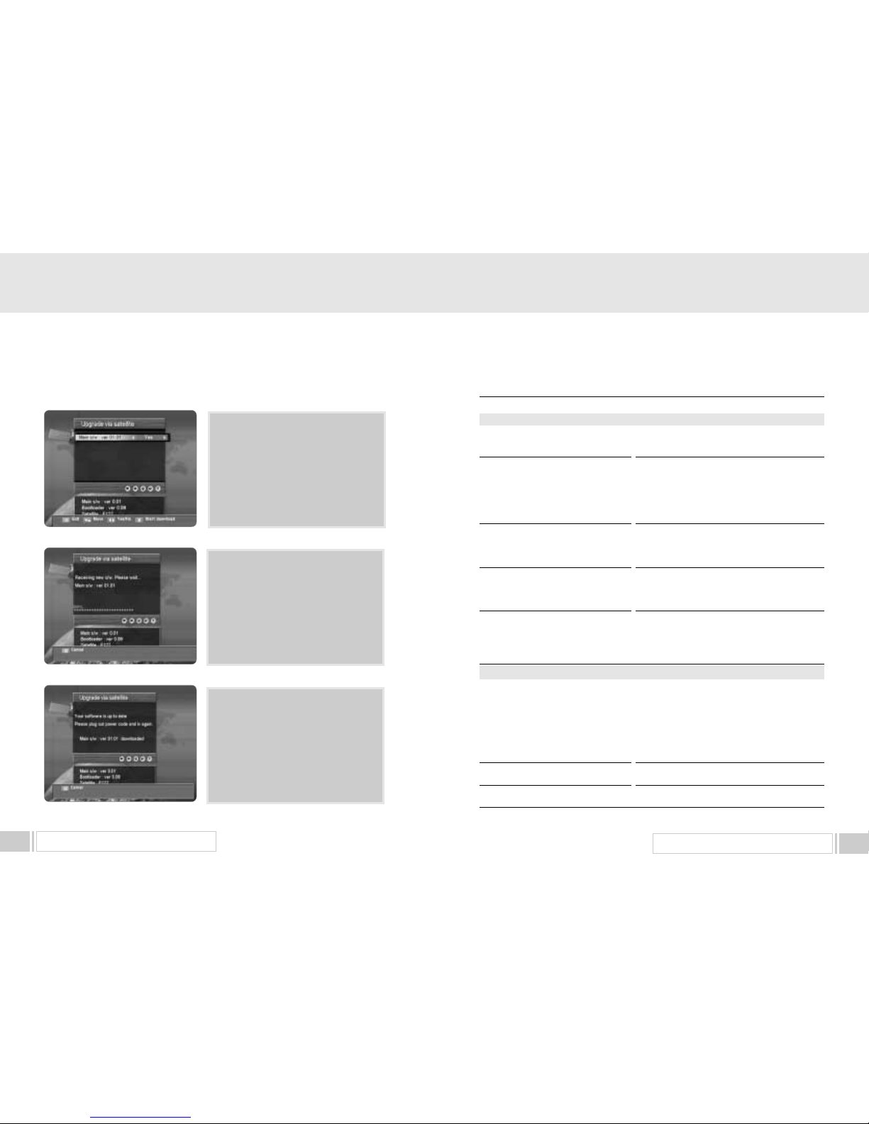
1.D. If new software found then the list of
new software and data will be displayed.
Select [Yes] or [No] for each item to
upgrade or not and press “ OK ” button
to start upgrade.
If you do not want to upgrade, press
“ EXIT ” key to return previous menu.
1.E. Receive and update new s/w. It takes
about 20 to 50 minutes.
You can stop upgrading at anytime
before download completes (e.g. before
progress bar reaches 100%).
But if download completes, you should
not switch off power until the message
as next step (1.F.) appears.
1.F. When download completes
successfully, you can see the message
in the left figure. At this moment,
you have to reboot the receiver to run
with new s/w.
8. TROUBLE SHOOTING
Problem
Does not display LED on the
front panel or the receiver has no power.
No pictures on the screen
No sound
Remote Control does not operate
Poor picture quality
Searching Signal
Unrecognized smartcard
Please insert your smartcard
Solution
- Connect the power cord to the power outlet
properly.
- Check if the receiver is in standby mode.
- Check if the video output port is firmly
connected to the Tv.
- Check if you have selected the correct
channel or video output on your TV.
- Connect the audio cords properly.
- Check the volume level of the TV.
- Press
MUTEkey.
- Point remote control directly towards the
receiver.
- Check and replace batteries.
- Check the signal strength in the
Automatic
Channel Searchmenu
- If this is low, try adjusting the alignment of
your dish.
- Connect the antenna cable properly.
- Check the LNB. Please replace LNB if
necessary.
- Check the position of the dish. Please realign
dish if necessary.
- Check the signal strength in the
Automatic
Channel Search
menu.
- Check the smartcard.
- Insert the smartcard.
About the Receiver
On - Screen Error Messages
Page 16
5. Audio Decoder
System Decoding
Audio Mode
Sampling Frequency
6. Audio/Video Output
TV SCART
VCR SCART
RCA Jack
S/PDIF
7. RF Modulator
Modulator Output
Video Type
UHF Output Level
Output Connector
Ant. IN Connector
Tuning Method
8. Serial Data Interface
Signal
Connector Type
9. Common Interface
Module Type
Available CAM
10. Embedded Descrambler
CryptoWorks Conditional Access System
: MPEG-1 ISO/IEC 11172-3
Layer I & II
: Mono, Dual, Stereo, Joint Stero
: 32, 44.1, 48 KHz
: CVBS, RGB, Audio L/R
: CVBS, Audio L/R
: CVBS, Audio L/R
: Digital Audio
: CH21
69 (Preset To CH38)
: PAL B/G, I, D/K
: 71
4 dBV
: IEC Male
: IEC Female
: PLL Frequency Synthesizer
: RS-232, Max. 38400 bps
: 9 Pin D-Sub(male)
: PCMCIA Type II
2
: Viaccess, Irdeto, Nagravision, Cryptoworks,
Conax, SECA
TECHNICAL SPECIFICATIONS28
1. Power Supply
Type
Input Voltage
Fuse Rating
2. Tuner
Input Frequency
Input Signal Level
Input Impedance
Connector Type
LNB Power Supply
22KHz Tone
DiSEqC
Channel Selection
3. Demodulator
Type
Symbol Rate
Inner FEC
Outer FEC
4. Video Decoder
System Decoding
Profile and Level
Data Rate
Video Formats
: SMPS
: 90
240VAC 50/60 Hz
: 250V/T2A
: 950
2150MHz
: -65
-25dBm
: 75
Unbalanced
:
FType Female
: 13V/18V, Max 500mA with Short Circuit Protection
: Frequency 22
4KHz, Amplitude 0.60.2Vpp
: 1.0 & 1.2 Version Compatible
: PLL Frequency Synthesizer
: QPSK Demodulation(DVB-S)
: 1
45 MS/s
: Viterbi Convolutional Coding
Rate 1/2, 2/3, 3/4, 5/6, 7/8
: Reed Solomon Coding(204,188) T=8
: MPEG-2 ISO/IEC 13818-2
: MPEG-2 MP@ML
: 1
15 MB/s
: 4:3(Normal) & 16:9(Widescreen)
9. TECHNICAL SPECIFICATIONS
 Loading...