

Page 1

Professional Power Amplifier
CLIPCLIP
SP200
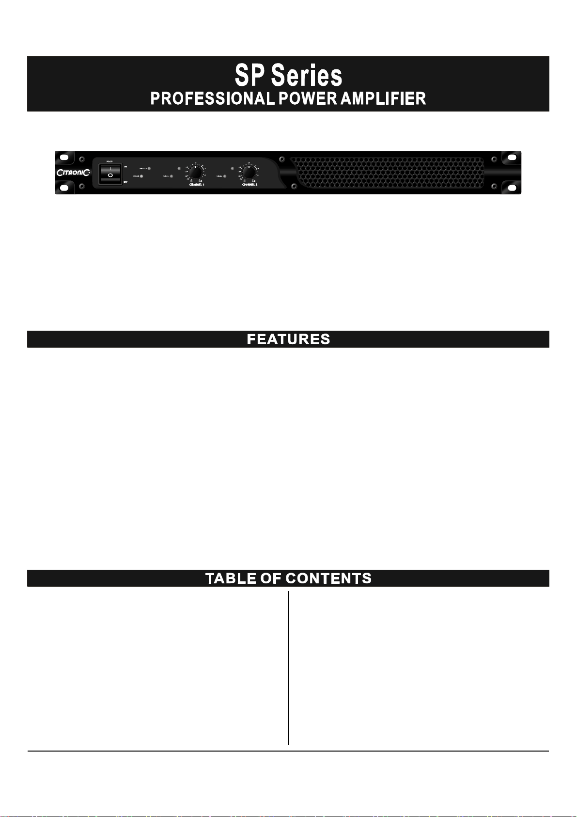
SP Series
Professional Power Amplifier
Before attempting to connect, operate or adjust this product, please read these instructions completely.
Rev: 2.0-CITRONIC-SP 11/2010
Page 2

Page 3
CLIPCLIP
SP200
Congratulations on your choice of stereo power amplifiers you have purchased one of the finest stereo amplifiers on
—
the market today. This unit was developed using the expertise of professional sound engineers and working musicians.
You will find that your new has superior performance and greater flexibility than any other amplifiers in its
SP Series
price range. Please read this manual carefully to get the most out of your new unit.
Thanks for selecting as your choice in stereo power amplifiers.
SP Series
Offering top power, superior performance and full professional operating features in a roadworthy compact chassis, the
SP Series
The operating instruction in this manual are for the power amplifiers. The operation and functions of these units
Bold Type are perfect for even the most demanding sound reinforcement installation and touring applications.
SP Series
are the same, except as noted.
Full operating features: detent volume controls ;replace Roadworthy, rugged double rack space (1U) housing
. .
with text 1/4 TRS jack balanced inputs speak on out ~115V AC 60Hz, ~230V AC 50Hz select switch and IEC
Full safety/reliability features: 2 variable speed fans for
.
"
.
cooling; noise-free on-off; DC and thermal
overload protection; short circuit and speaker protection;
Power ON, Clip, Signal, and Protect LED indicators for each
.
channel
FEATURES ............................................................... 3
WARNING ................................................................. 4
FRONT & REAR PANEL CONNECTIONS .................... 5
INSTALLATION ........................................................ 6
SPECIFICATIONS ..................................................... 7
Date of Purchase ______________________________
Dealer sName _______________________________
,
City _________________________________________
State __________________ Zip __________________
Model # ______________________________________
Serial # ___________________
3
Page 4

CAUT IO N
CAU TION:
TO RED UCE THE RISK OF EL ECTRI CS HOCK
DO NOT R EMOV ECO VER (O R BAC K).
NO USER SE RVICEA BLE PARTS INS IDE.
REFER S ERVICI NG TO QU ALIF IED SERVI CE PER SONNE L.
An e qui latera l triangle en closi ng a lighteni ng flash/arro whead sym bo l is
int ended to al ert th eu ser to the pres ence o f unins ulated "dan gerou s
volta ge" wit hin the pro duct s enclos ure wh ich may b e of suffic ient
magnitu de to constit ute a risk of e lectric sho ck.
An e qui latera l triangle en closi ng an excla mation po int is in tended to alert
the u ser to the presen ce of imp ortant operatin gand serv ice i nstru ctio ns in
the l iterature enc losed w ith th is un it.
When using this el ec tr oni c device, basic p recaution s should always be t ak en , inclu ding the fol low ing:
1. Re ad all in structi on s before using the product.
2. Do not use thi s product near water (e.g., near a bathtub , was hb ow l, kitchen sink , in a wet baseme nt, or near a swimmi ng
pool, etc.).
3. This product should be use d o nly with a c art or sta nd that wi ll k eep it level an d stabl e an d prevent wobbli ng.
4. This product, in co mbinatio n with head phones or speake rs, may be c apable of producing sound l e vel s t hat co ul d cau se
perman en t hearing lo ss. Do not opera te for a long pe rio d o f ti me at a high volume lev el o r at a lev el t hat is uncomfortable.
If you experience any h earing loss or r in g ing in the ears, yo u should consult an aud iolog is t.
5. The pr odu ct sho ul d be p os itioned so that proper ven tilation is maint a ined.
6. The pr odu ct sho ul d be l oc ated away f rom heat source s such as radia tors , h eat vents, or other devi ces
(includi ng am plifie rs) that produce heat.
7. The pr odu ct sho ul d be con necte d to a p o wer supply only o f the type desc ri be d in the ope rating instructions or as marked on th e
product. Replace the fu se only wit h on e of the specified t ype, size , and co rrect ra ting.
8. The po w er supply cord sho ul d : (1) be undamaged, (2) neve r shar e an o ut let or extension cor d wit h other devi ces s o that the
outlet's or exten si on cord 's power rating is exceeded, and (3) ne ve r be le ft p lugged into the outle t w hen not being use d for
a long period of ti me.
9. Ca re should be taken s o t hat objects do not fa ll i nt o, and liquids are no t spill ed thro ugh, the encl o su re's openings.
10. The prod uct sh ou ld be servi ced by qu a lified ser vi ce perso nnel if:
A. T he power supply c ord or the pl ug has be en damaged.
B. Ob jects have fall en in to, or li qu i d ha s be en spill ed onto th e product.
C. The pr od uc t has be en expos ed to ra in.
D. The pr od uc t doe s not app ear to o pe ra te normally or e xh ibits a marke d change in perfo rm anc e.
E. The product has b een dro pped, or the enclosur e dama ge d.
11. Do n ot attem pt to servi ce the product beyo nd w ha t is de scri bed in the user mainte na n ce instructi o ns. All oth er ser v icing shou ld
be referre d to qualifie d service pe rsonnel.
4
Page 5

5
3
CLIPCLIP
2
61 6
4
FRONT PANEL
1. POWER SWITC H
To turn the un it ON or OFF, press the Left or Right portion of
this button. Before tur ning on th e amplifier, check all conn ections
and turn down the level controls. A momentary muting is normal
when turning the ampl ifier on or off.
(Caution: Alw ays turn on your power am plifier las t, after all your
other connec ted equi pment, and alway s turn off your pow er
amp lifier befo re your other connected equipment.)
2. POWER LED I NDI CATORS
Thes e L
3. LIMIT LED I NDICATORS
Thes e LEDs i lluminate if any section of the power amplifie r's
output are wit hin 3dB of clipping . Occasional blin king of the LEDs
are acceptable, but if they remain on more than in termitte ntly you
should turn down either the pow er amplifier s lev el contro ls or
EDs illuminate when th e power is turned "ON".
SP200
reduce the output level of the p receding component to avoid
audible distor tion.
4. S IGNAL L E D INDICATORS
Thes e LEDs i lluminate to confirm the presence of an inpu t signal
greater than 1 00 mV at that cha nnel of the a
mplifier
5. P ROTE CT L ED INDICATORS
Thes e LEDs i lluminate if the po wer amplifier s ou tput connection
is shorted or the load impedanc e is too low. When either o f these
LED s is lit up, turn OFF the pow er and c heck the output's connection to verify that it is correct, th en turn ON the po wer agai n.
6. L EVEL CONT RO LS
Thes e contro l the level of signa l coming into each chan ne l. The
actual voltage gain of the amplifier is shown in dB. Turn th ese
controls countercl ockwise if the peak LEDs illuminate steadily
(indicating too strong an inp
ut signal).
13
BACK PANEL
7. POWER CONN ECTOR
The cord con nector is used to c onnect the AC power source to
your power amplifier.
(CAU TION: DO NOT REMOVE THE CE NTER GROUNDING
PIN. )
8. FUSES
Fuse holders.If these fuses continuously blow, shut off the unit
and have it serviced by qualified service p ersonne l.
9. AC VO LTAGE SEL ECTOR SWITCH
Before plugg ing in the power cord, check to see that the unit is set
for th e proper voltage for your area:~115V(60Hz)or ~230V(50Hz).
10
ON
OFF
12
11
9
10. INPU T CON N ECTO RS
Connect your input signal to the se balanced 1/4"TRS input jacks.
11.L /R CH ANNE L O UT P UT CONNECTORS
Connect to your speaker box.
12. BUI LTIU LIMI TER ON/OFF SELECTO R
13. FANS
The fan spee d is varied continu ously an d automatically to maintain
the proper int ernal ope rating temperature.
5
7
8
Page 6

Toensure years of enjoyment from your , please read and understand this manual thoroughly before using the unit.
SP Series
INSPECTION
Your
SP Series
designed to protect the units in shipment. Before installing and
using your unit, carefully examine the packaging and all contents
for any signs of physical damage that may have occurred in
transit.
(Note: is not responsible for shipping damage.
SP Series
Remove If the unit is damaged, do not return to us, but notify
your dealer and the shipping company immediately to make a
claim. Such claims must be made by theconsignee in a timely
manner.)
was carefully packed at the factory in packaging
CONTENTS
Instruction manual
.
. SP Series
shown on shipping carton)
AC Power cord
.
(verify that the unit's serial number is same as
RACK MOUNTING
The amplifiers are designed for standard 19" rack
SP Series
mounting as well as "stack" mounting without a cabinet. Use 4
screws and washers for mounting to the front rack rails. It is also
a good idea to support the amps also in the rear, especially for
mobile use where the amps will be subjected to shocks.
AMPLIFIER COOLING
Also pay close attention to the cooling requirements. Never block
the air vents in the back, side and front of the amplifier if the load
seen by amplifier is less than 4 ohms and the amplifier is being
run at high output levels. For best results, in such high output
powerapplications you should augment the amplifier's air flow
with a rack cooling system.
6
Page 7

POWER SPECIFICATIONS
SP200 SP400
STEREO INTO (4 )
STEREO INTO (8 )
Ω
Ω
POWER SPECIFICATIONS
INPUT SENSITIVITY
INPUT IMPENDANCE
FREQUENCY RESPONSE
(at 10db below rated output power)
DISTORTION (SMPTE-1M)
S/N RATIO
GENERAL SPECIFICATIONS
PROTECTIONS
100W
70W
200W
130W
SP200 SP400
0.77V
10k balanced
Ω
25Hz~25KHz +0/-1dB -3dB points:5Hz~50KHz
<0.03%
100dB
SP200 SP400
Full short circuit, open circuit, thermal, Ultrasonic, and
Protection; stable into reactive or mismatched loads; ON/OFF
muting; current limiter
RF
CONTROLS
INDICATORS
CONNECTORS
POWER SUPPLY
FUSES (250V)
DIMENSIONS
WEIGHT (kg)
The specifications above are correct at the time of printing of this manual. For improvement purposes, all
specifications for this unit, including design and apperance, are subject to change without prior notice.
Front: Power switch, 41 detent input level control for each channel.
SIGNAL: 2 x green LED
LIMIT: 2 x red LED
POWER: 1 x blue LED
PROTECT: 1x red LED
POWER: IEC power cord
INPUT: 1/ 4" (6.3mm)TRS
OUTPUT: SPEAKON
Voltage selectable: 115V AC 60Hz 230V AC 50Hz
AC115V:T4A/250V
AC230V:T2A/250V
19.0 x 12.6 x1.73 (482 x 320 x 45mm)
"" "
8.0Kg
AC115V:T6.3A/250V
AC230V:T3.15A/250V
8.3Kg
7
Page 8

 Loading...