

Citronic SM650, SM550 Owner's Manual
rIITI
CrponlC
SM65O
INIII
PROFESS
IONAL
MIX
ING
DESK
SM55O
TEIII
PROFESS
IONAL
MIX
ING DESK
OWNER'S
MANUAL
IIIII
Itllr
2, SM65O
FRONT
&
REAR PANEL
3.
INTRODUCTION
4. WARRANTY &
SAFETY
(TMPORTANT)
7. TECHNICAL SPECIFICATIONS
&
FEATURES
Mlc 1 and
Mic
2
lnput
Channels
rl-4
Maln
AB
Output
Monltorlng
Auxlllary
Systems
lnfll
Systems
Eq lnsert
16. INSTALLATION
AND
USE
Before You
Start
Aux Effects and
lnfil
Systems
Uslng
The Front Panel
Controls
Mlxlng
Facilities
19.
INTERNAL
OPTIONS
21
. AUDIO
SPECIFICATIONS
22,
BLOCK
SCHEMATIC DIAGRAMS
26. INDEX
25.
SM55O
FRONT
&
REAR
PANEL
CENTRE
PULLOUT
DJ
User
Guide
xo.€{
w
.*,'
jr"ry!9"f,.:jlnrH
*,;;:#,.*,
#'***
*
PROGRAI
SEND
.,ffi_
ffi.
C
fl
CmronlC==
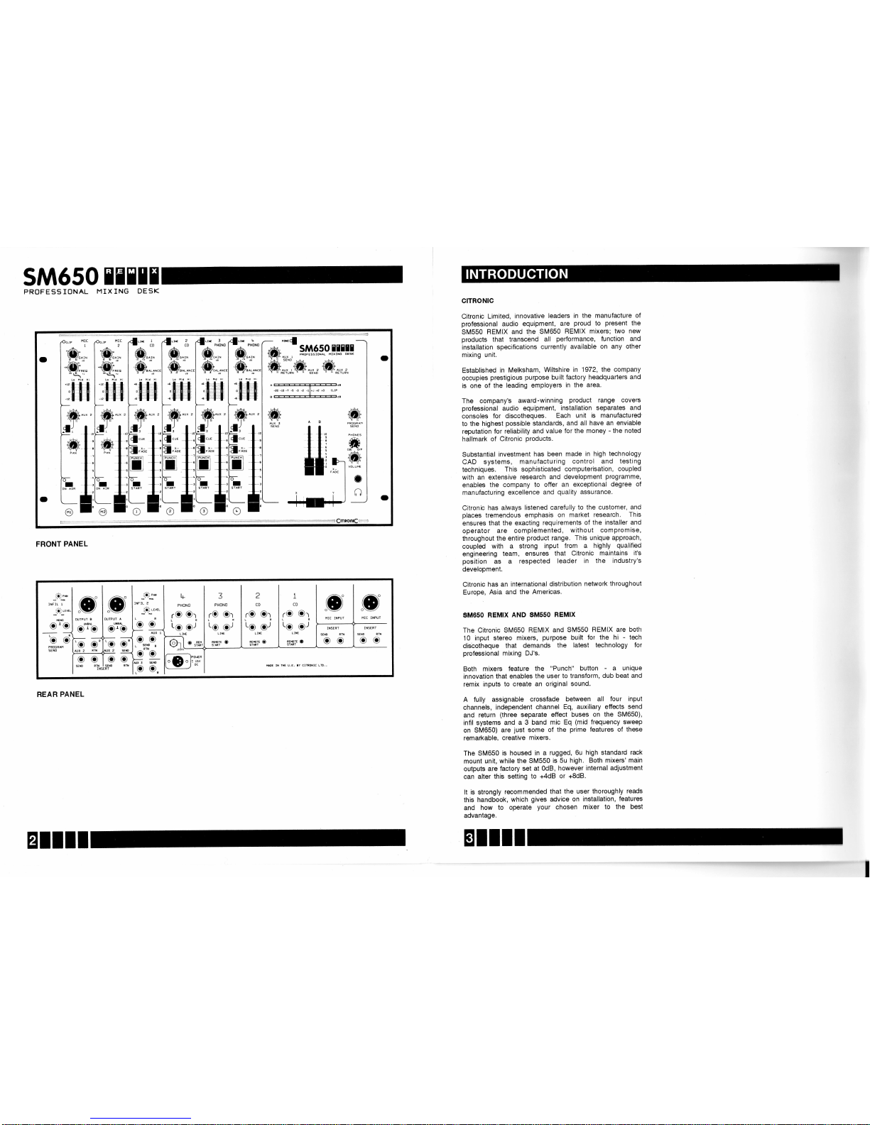
FRONT
PANEL
t+
PHONO
rc
ct
'o--.o'
3
PHONO
re
Cr
LR
L6
gJ
L INE
nercre
Q
STA,RT
2
CD
rO
er
LR
Lg
gJ
L IIIE
ginr
o
I
CD
rO
Or
LR
Lg
gr
L IIIE
nercru
Q
STAPT
o
"o.
REAR
PANEL
ctTRoNlc
Citronic
Limited,
innovative
leaders
in the manufacture
of
professional audio
equipment,
are
proud
to
present
the
SM550
REMIX
and
the SM650
REMIX
mixers;
two new
products
that
transcend
all
performance, function and
installation
specifications
currently
available
on
any other
mixing
unit.
Established
in Melksham,
Wiltshire
in
1972, the
company
occupies
prestigious
purpose
built
factory
headquarters
and
is
one of
the leading
employers
in the
area.
The company's
award
-winning
product
range
covers
professional
audio
equipment,
installation
separates and
consoles
for
discotheques.
Each
unit is manufactured'
to
the
highest
possible
standards,
and
all have
an enviable
reputation
for reliability
and
value
for the money
-
the noted
hallmark
of Citronic
products.
Substantial
investment
has
been
made
in high technology
CAD
systems,
manufacturing
control
and testing
techniques.
This
sophisticated
computerisation,
coupled
with
an
extensive
research
and
development
programme,
enables
the
company
to
offer an
exceptional
degree
of
manufacturing
excellence
and
quality
assurance.
Citronic
has always
listened
carefully
to the
customer,
and
places
tremendous
emphasis
on market
research.
This
ensures
that
the
exacting
requirements
of
the
installer
and
operator
are
complemented,
without
compromise,
throughout
the
entire
product
range.
This unique
approach,
coupled
with
a
strong
input
from
a highly
qualified
engineering
team,
ensures
that
Citronic
maintains
it's
position
as
a
respected
leader
in the
industry's
development.
Citronic
has an
international
distribution
network
throughout
Europe,
Asia and
the
Americas.
SM65O REMIX
AND
SM55O
REMIX
The
Citronic
SM650
REMIX
and
SM550
REMIX
are
botl"t
10
input
stereo
mixers,
purpose
built
for the hi
-
tech
discotheque
that demands
the
latest
technology
for
professional
mixing DJ's.
Both
mixers
feature
the "Punch"
button
-
a
unique
innovation
that
enables the
user
to transform,
dub beat
and
remix
inputs
to create
an
original
sound.
A fully
assignable
crossfade
between
all
four
input
channels,
independent
channel
Eq, auxiliary
effects
send
and
return
(three
separate
effect
buses
on the
SM650),
infil
systems
and
a
3 band mic
Eq
(mid
frequency
sweep
on SM650)
are
just
some
of the
prime
features
of these
remarkable.
creative
mixers.
The
SM650
is housed
in a
rugged,
6u high standard
rack
mount
unit,
while
the
SM550
is
5u high.
Both mixers'
main
outputs
are factory
set at
OdB, however
internal
adjustment
can alter
this
setting
to +4dB
or
+8d8.
It is
strongly
recommended
that
the user
thoroughly
reads
this
handbook,
which
gives
advice
on installation,
features
and
how
to
operate
your
chosen
mixer
to
the best
advantage.
EIIII
Wiring
WARNING
-
THIS APPARATUS
MUST
BE
EARTHED
IMPORTANT: The wires
in
the mains lead
are coloured
in
accordance
with the following
code:
Green
and Yellow
Blue
Brown
: Earth
:
Neutral
: Live
As the
colours
of the
wires in
the mains
lead of
this
product
may
not correspond
with
the coloured
markings
identifying
the
terminals in
your
plug, proceed
as
follows:
The
green
and
yellow
wire must
be connected
to the
terminal
marked
"E"
or
shown
by the safety
earth
symbol
or coloured
green
or
green
and
yellow.
The
blue wire
must be connected
to the
terminal
marked
"N",
or coloured
black.
The
brown
wire
must be connected
to the
terminal
marked
"L",
or coloured
red.
Earthlng
IMPORTANT
-
Both
mixers
are hard-ear1hed,
ie.
mains
earthed
equipment.
Lift the
signal
eafth
from
all other
ancillary
equipment
to
avoid earth
.
loops,
which
create
unwanted
buzz
and
hum.
Under
no clrcumstances
should
you
disconnect
the
earth
wlre
ln
the maln
AC supply
of any
ancillary
equlpment.
Consult
the
relevant
manual
supplied
in order
to lift
the
signal
earth
correctly.
The Citronic
SPX
range of
processors
are sott-earthed
and
no
adjustment
is
required
for complete
compatibility
with the
SM
range.
The PPX
range of amplifiers
feature
an earth
lift switch
on the
rear
panel,
enabling
you
to harmonise
your
sound
system
by using
only
top
quality
Citronic
products.
Power supply
The mixer is supplied
with
it's own separate
power
supply
unit which may
be
mounted
in any
position.
Care should
be taken,
however,
to ensure that
there
is adequate
ventilation
around
the
power
supply
heatsink,
and
that
all
signal
wiring is
routed away
from
the
power
supply.
The voltage rating
is
factory
set to
match
European
and
U.K.
standards,
ie.
220-240V.
Check this
setting
on the
rear
of
the unit.
For use
in Canada
and the USA,
the
voltage
rating should
be set
at 110
-120V.
ln
order
to comply
with
international
safety
standards,
power
supplies
are
fitted with
a moulded
multi-standard
mains
plug.
For
use
in the U.K.
this
plug
will need
to
be
replaced
with a standard
13
amp
plug
fitted
with a 3
amp
fuse.
Slgnal connectlons
Make
all connections
to turntable,
CD
and tape decks using
good
quality
stereo
phono
or RCA
phone
Jack leads. The
importance
of this is often
overlooked,
and is the frequent
cause
of complaints
about
poor performance
and
output
quality.
lmportant
note:
-
SM650
only
Your
mixer will have
been
supplied
with four
Phono
Jump
leads which
you
may
need
to insert,
please
refer
to
the
section
"lnstallation
and
Llse"
BEFORE
attempting
to
operate
the
SM650.
Remote
starts
Both
latching
action
and
momentary
action
remote
stafi
switches
.
are suitable
for
low voltage,
low current
applications
only.
Under
no
circumstances
should
mains-connected
or
high current
loads
be switched
directly.
As
with
all equipment,
if
you
are
in any
doubt,
consult
your
dealer.
Packaging
Ensure
that
all faders
are set
at the
maximum
before
attempting
to
replace
the
mixer
in its
original
packing
case.
lf
this is
not
done,
they
will
foul on
the inner
packing
material.
MAINTENANCE
AND GUARANTEE
Maintenance
NO SPECIAL
PREVENTATIVE
MAINTENANCE
IS
R EQU
IH ED
As with
all
high
quality
audio
equipment,
the
overall
performance
is
highly
dependent
upon
healthy
connection
leads.
lt is
therefore
essential
that
these
are checked
periodically
for
wear
and tear
and
replaced
as
necessary.
Although
all Faders
are
vedically
mounted,
it
is
still
important
to
avoid
spilling
liquid
onto
your
mixer,
as this
may
cause
damage
to
the
precision
electronics.
Guarantee
This
product
is
guaranteed
to the
original
purchaser
against
defects
in
material
and
wokmanship
for
one
year
from
the
date of
initial
purchase.
Activate
this
guarantee
at the
time
of
purchase
by
returning
the Guarantee
card
to
the
address
below.
Keep
a copy
of
your
sales
receipt
for
proof
of
guarantee
status,
should
it be
necessary.
lf
a
malfunction
occurs,
the dealer
who
supplied
the unit
wilr
be
happy to
handle
the
repair.
When
returning
a unit,
use
the
original
factory
carton
-
do not chance
inadequate
packing
materials.
Simply
tape
a
note
to
the top
of
the
unit
describing
the
malfunction.
lf
your
unit
is out
of
guarantee,
we
recommend
that
you
return
it
to
an authorised
Citronic
dealer
for
repair
or
service.
Experienced
personnel,
supported
by specialist
testing
equipment,
will be
able
to find
and correit
the fault
in
the
most efficient
and
cost-etfective
way.
ln
the
UK:
Citronic
Limited
Halifax
Road
Bowerhill
Melksham
Wiltshire
SN12 6UB
Telephone:
(0225)
705600
Fax:
(0225)
709639
ITTIr
SM65O
TEEII
PROFESSIONAL
MIXING
DESK
SM55O
TEIIT
PROFESSIONAL
MIXING
DESK
INSTALLERS
GUIDE
EIIII
IIIIE
For reference
purposes,
the
mixer
has
been
split
into
sections,
namely:
Mic
lnputs
1 and 2;
Music
lnPut
Channels
1-4;
Channel
A and
Channel
B
Output
(Rear);
Channel
A and
Channel
B
Output
(Front);
Monitor
Section;
Auxiliary
and
lnfil
SYstems.
Each
section
details
the
rear and
front
of
the
mixer
where
applicable,
and is
illustrated
with a
schematic
diagram
or
drawing
to act as
a
quick
visual
aid.
ln addition,
each
part
of
the
mixer is
numbered
to
correlate
with
the
written
information.
.:.:.:.:.:.:...:.:..'.':.......:.:....'.......':.:...:.....:':.:'......:..':':..'.'."'..'.'
i:i:ftr;
Uit
iii;tea
wath
;
gi"y
box
surround
ocscriues,:,:
,i,ifeatures
that are
found
on the
SM650
only, and
do not,,;'
::::ennly
!9 9w19T?
9l !P
9M9!9,
::::
A
full view
of the
front and
rear
panels
for
the
SM650
and
SM550
are
shown
on the inside
of the front
and
back covers,
pages
2 and
25 respectively.
These
can
be
folded
out whlle
you
refer
to the manual.
lmportant
Note
Both
mixers
feature
a
common
auxiliary
effect
loop, known
as
AUX2 on
the SM650,
and AUX
on the
SM550.
For
reference
purposes,
this
loop
will be indicated
as AUX2
throughout
this
manual.
Owners
of
the SM550
should,
therefore,
relate
the
information
to their
AUX controls.
Any
reference to
0dBm
on control
dials assumes
that the
input
has been
cued
to the blue
OdB
marker
on the Bar
Graph
Display
and
that
preceding
level controls
are
at
maximum.
D
D
D
D
D
E}
MIC
2
REAR
PANEL
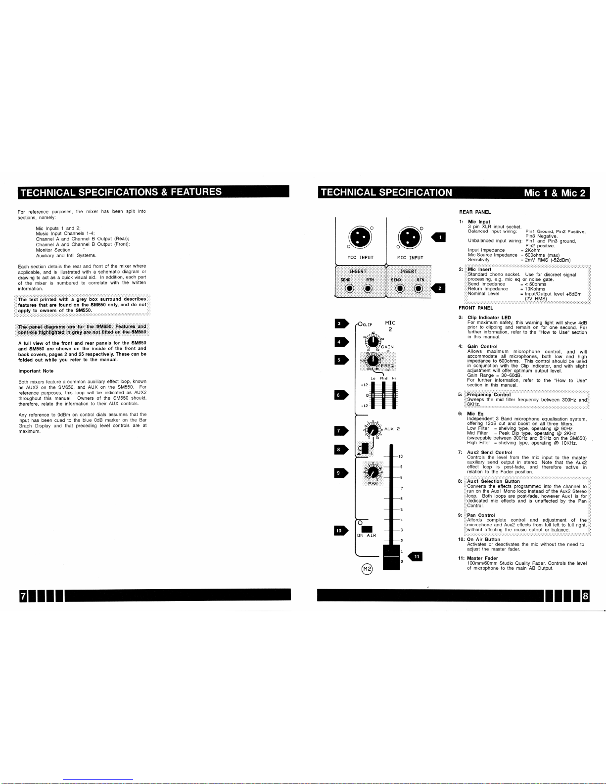
1:
Mic lnput
3
pin
XLR
input
socket.
Balanced
input
wiring:
Unbalanced
input
wiring:
Pin2
Positive,
ground,
3: Clip
lndicator LED
For
maximum
safety,
this
warning light
will show
4dB
prior
to clipping
and
remain
on for
one
second.
For
fufther information,
refer
to the
"How to Use"
section
in this
manual.
4: Gain
Control
Allows
maximum
microphone
control,
and
will
accommodate
all microphones,
both
low
and
high
impedance
to 600ohms.
This control
should be
us6d
in conjunction
with the
Clip
lndicator,
and
with slight
adjustment
will
otfer
optimum
output
level.
Gain
Range
=
30-60d8.
For
further
information,
refer
to
the
"How
to Use"
section
in this
manual.
S:
,i,iFrequdrricy
Coritfol
,::,
i,;,Qweeps
the
mid
filter frequency
between
300H2
and,,i,
..:.
6:
Mic
Eq
ln-dependent_3
Band
microphone
equalisation
system,
offering
12dB cut
and
boost on
all
three filters.
Low Filter
=
shelving
type,
operating
@
90H2.
Mid
Filter
=
Peak
Dip
type,
operating
@
ZKHz
(sweepable
between
300H2
and SKHr
on
the SM650)
High Filter
=
shelving
type,
operating
@
1OKHz.
7:
Aux2
Send
Control
Controls
the level from
the mic input
to the
master
auxiliary
send output
in stereo.
Note that
the
Aux2
effect
loop
is
post-fade,
and
therefore
active
in
relation
to the
Fader
position.
8:
::::Auxl
Selection
Button
,,i,
ii,'Converts
the effects
programmed
into the channel
to
i:i,
i:i:run
on
the Auxl
Mono
loop
instead
of the
Aux2 Stereo::ii
,',,loop.
Both loops are
podt{ade,
however
Auxl is
fori:i:
:i:idedicated
mic effects
and is unaffected
by
the
pan
i,ii
:,iiOontrol.
:i:i
l:l:
g:
iiiiPan
Control
::::
:i,iAffords
complete control and
adjustment
of the:':,
:,i,microphone
and Aux2 effects from
full left
to full right,:i:i
i':'without
affecting the music output
or balance.
,i,'
10: On
Air
Button
Activates or deactivates
the mic without
the need to
adjust the
master fader.
11: Master Fader
100mm/60mm
Studio
Quality
Fader.
Controls
the level
of
microphone to
the main AB Output.
+12
0
-12
o
I
ON
AIR
EIIII
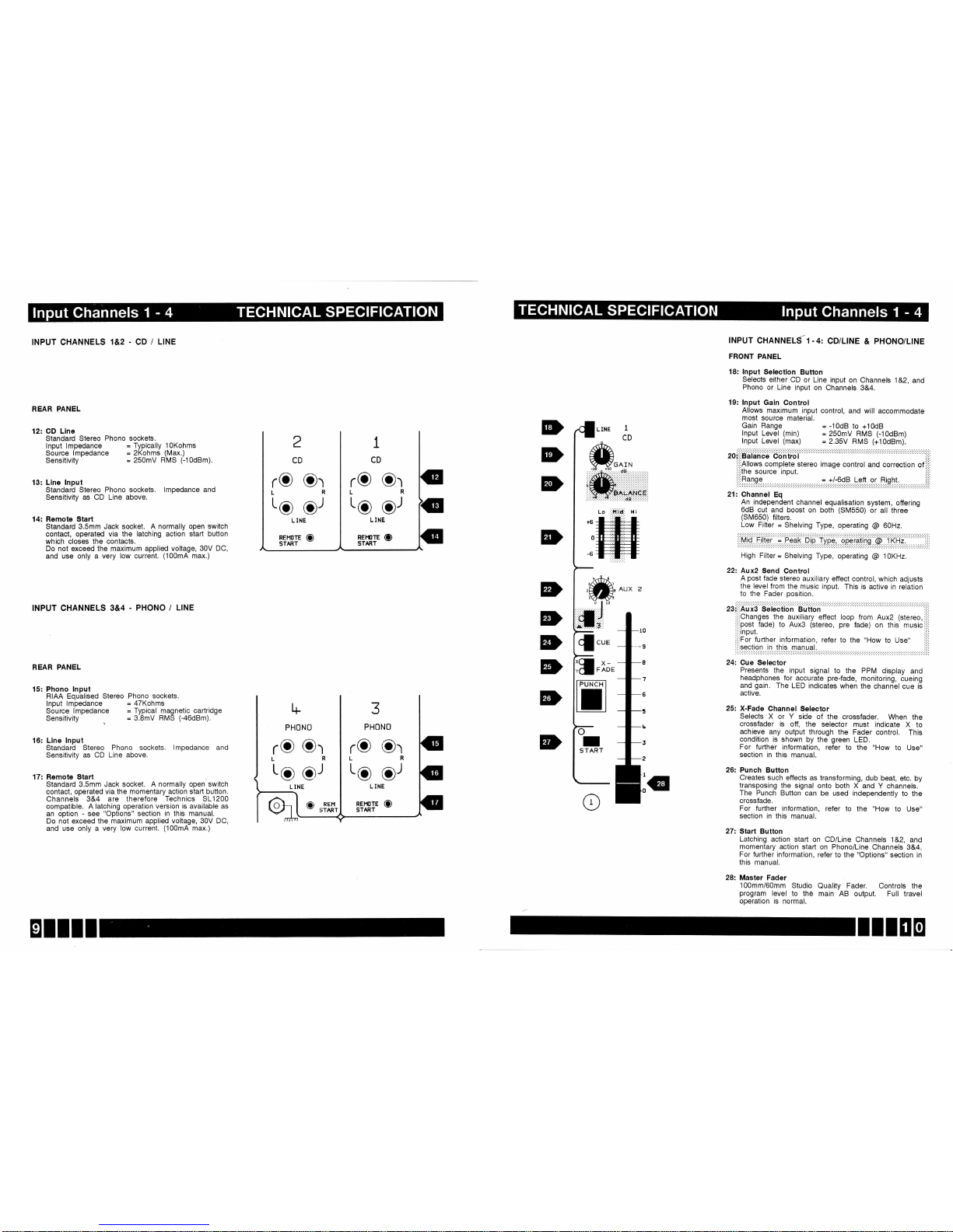
INPUT CHANNELS
1&2
-
CD /
LINE
REAR
PANEL
12:
GD Llne
Standard
Stereo
Phono sockets.
lnput lmpedance
=
Typically
l0Kohms
Source
lmpedance
=
2Kohms
(Max.)
sensitivity
=
250mV
RMS
(-10dBm).
13:
Llne lnput
Standard
Stereo
Phono
sockets.
lmpedance and
Sensitivity as
CD Line above.
14: Remote Start
Standard 3.5mm Jack
socket. A normally
open switch
contact, operated via the
latching action
start button
which
closes the
contacts.
Do not
exceed the maximum
applied voltage,
30V DC,
and use only
a very low
current.
(100mA
max.)
INPUT CHANNELS
3&4
PHONO
/
LINE
I
CD
INPUT
CHANNELS-1.4:
CD/LINE
&
PHONO/LINE
FRONT
PANEL
18: lnput
Selectlon
Button
Selects
either
CD
or Line
input
on
Channels
1&2,
and
Phono
or
Line input
on
Channels
3&4.
19: lnput
Gain
Control
Allows
maximum
input
control,
and
will accommodate
most
source
material.
Gain
Range
=
-10d8
to
+10d8
lnput
Level
(min)
=
250mV
FIMS
(-10dBm)
lnput
Level
(max)
=
2.35V
HMS
(+10dBm).
20::::Balance
Control
,i,i
:,:'Allows
complete
stereo
image
control
and correction
of
i::i
:':,tne
source
input.
i'i'
t,tiflglgg. . .=.t/:6dB
Left
or Right.
:i:i
21:
Channel
Eq
An_independent
channel
equalisation
system,
offering
6dB
cut
and boost
on
both
(SM550)
or
all three
(SM650)
filters.
Low
Filter
=
Shelving
Type,
operating
@
GOHz.
i:iMiQ
fiter ;
P.-e?li
Dip- tipi,
qpiteriils
@:f
RHi:
i:i:
High
Filter
=
Shelving
Type,
operating
@
1OKHz.
222
Aux2
Send
Control
A
post
fade
stereo
auxiliary
effect control,
which
adjusts
the
level from
the
music input.
This is active
in relation
to the Fader
position.
Presents
the input
signal
to
the PPM
display
and
headphones
for
agcurate
pre-fade,
monitoring,
cueing
and
gain.
The
LED
indicates
when the
channel
cue
is
active.
25:
X-Fade
Channel
Selector
Selects
X or Y
side
of the
crossfader.
When
the
crossfader
is off,
the
selector
must
indicate X to
achieve
any output
through
the
Fader control.
This
condition
is shown
by
the
green
LED.
For
further
information,
refer to
the
"How
to
Use"
section in this
manual.
26:
Punch
Button
Creates
such
effects
as transforming,
dub
beat, etc.
by
transposing
the signal
onto both X
and Y channels.
The
Punch
Button can
be used independently
to
the
crossfade.
For
further information,
refer to
the
"How
to
Use"
section in
this manual.
27: Start
Button
Latching action
start on
CD/Line
Channels
1&2,
and
momentary
action staft
on Phono/Line
Channels
3&4.
For
further information,
refer to the
"Options" section
in
this
manual.
28:
Master Fader
100mm/60mm
Studio
Quality
Fader. Controls
the
program
level
to the
main AB output.
Full travel
operation
is normal.
2
CD
1
CD
L INE
REl.trTE
(D
START
*.^,_
-r0
+10
.
:.:. :. :.;{Lt. :. :':. :. :. 9
E,
:':.:. :. :.:.
iffiil
lli
Lo
,'ttii*,
H i
tffi
REAR
PANEL
15: Phono lnput
RIAA Equalised
Stereo
lnput lmpedance
Source lmpedance
Sensitivity
Phono sockets.
=
4TKohms
=
Typical magnetic
cartridge
=
3.8mV RMS
(-46dBm).
16: Llne
lnput
Standard Stereo
Phono
sockets. lmpedance
and
Sensitivity as
CD Line above.
17: Remote
Start
Standard
3.5mm Jack socket. A
normally open switch
contact, operated
via the momentary
action staft button.
Channels 3&4 are
therefore Technics
SL1200
compatible.
A latching
operation version is
available
as
an option
-
see
"Options"
section
in
this manual.
Do
not exceed the
maximum applied
voltage, 30V DC,
and use
only a very low
current.
(100mA
max.)
rO
Or
rO
Or
to..,-9'
REHOTE
(D
START
L6
oJ
D
D
D
D
D
D
D
ED
Lg
or
(D
REr'l
START
L INE
REi,tlTE CD
START
IIIEO
 Loading...