

Page 1

Professional Power Amplifier
POWER
PPX900
ON
OFF
CHANNEL 1
PROTECT
CLIP
SIGNAL
CHANNEL 2
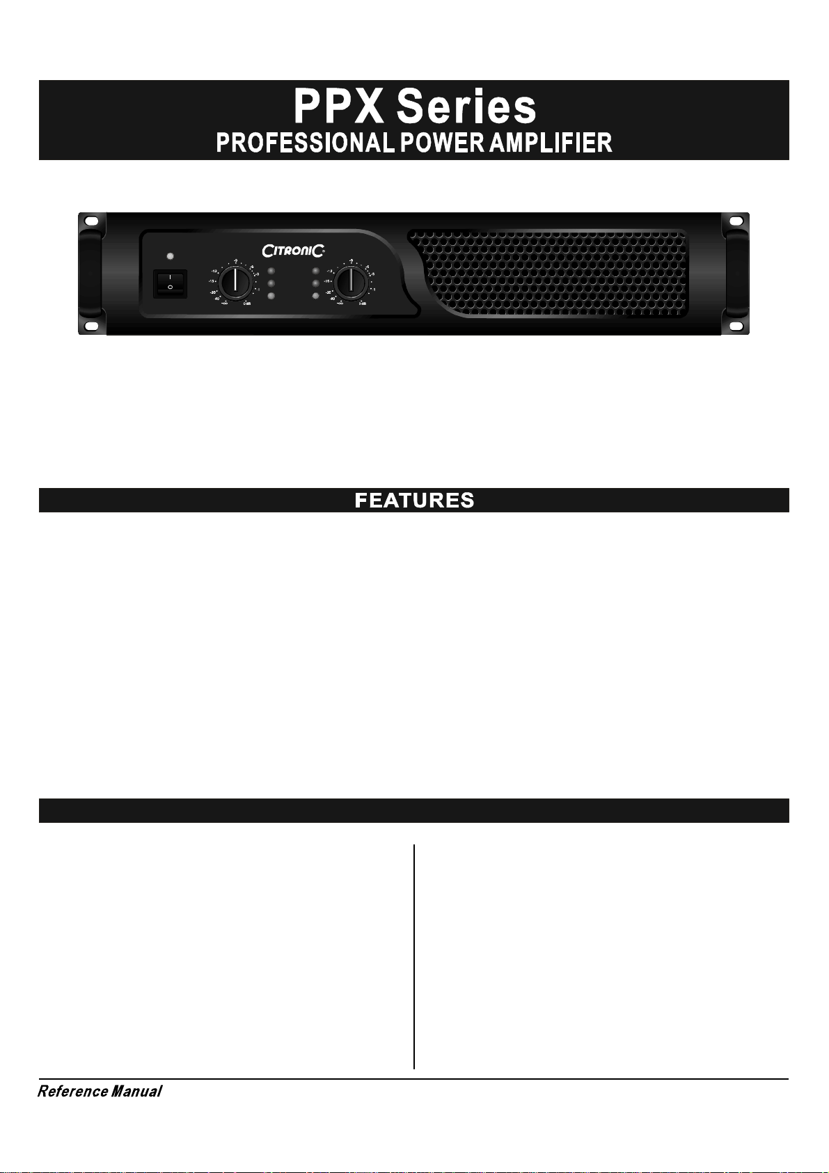
PPX
Series
Professional Power Amplifier
Before attempting to connect,operate or adjust this product,please read these instructions completely
Rev: 2.0-CITRONIC-PPX 11/2010
Page 2

Page 3
POWER
ON
OFF
PPX900 CHANNEL 1
PROTECT
CLIP
SIGNAL
CHANNEL 2
Congratulations for choosing Series professional power amplifier. You purchased one of the finest
CITRONIC
PPX
stereo amplifiers on the market today. This unit was developed using the expertise of professional sound engineers
and working musicians. You will find that your new Series amplifier has superior performance and
CITRONIC
PPX
greater flexibility than any other amplifiers in its price range. Please read this manual carefully to get the most ou t of
your new unit.
Offering top power, superior performance and full professional operating features in a roadworthy compact chassis, the
Series are perfect for even the most demanding sound reinforcement installation and touring applications.
PPX
The operating amplifier instruction in this manual are for all the Series professional power amplifiers. The operation
PPX
and functions of these units are the same, except as noted.
. .
Full operating features: detent volume controls; parallel bal- Roadworthy, rugged steel chassis (2U)
anced XLR and 1/4" TRS inputs; stereo (dual channel), parallel- Modular construction for easy servicing
.
input, or bridged mono operating modes with selector switch;
Independent user defeatable clip limiters (compressor) 3
selectable input sensitivities, ground lift switch, binding post
(banana plug) and speakon outputs.
.
Full safety/re liability features: 2 dual speed fans for cooling;
soft start turn on, noise-free on-off; independent DC and thermal
overload protection on each channel; short circuit and speaker
protection; built-in current limiter.
.
Front panel led indicators:Active, Signal, Limit and protection
Table of contents
FEATURES ............................................................... 1
WARNING ................................................................. 2
INSTALLATION........................................................ 2
FRONT & REAR PANEL CONNECTIONS ................... 3
SPECIFICATIONS .................................................... 4
For your records
Date of Purchase ______________________________
Dealer s Name ________________________________'
City _________________________________________
State __________________ Zip __________________
Model # ______________________________________
Serial # ___________________
Page 1
Page 4

CA UTION
CAUTIO N:
TO RED UCE THE RISK OF E LECT RIC SHO CK
DO NOT REMO VE COVE R( OR BAC K).
NO USE R SERVI CEABL E PARTS IN SIDE .
REF ER SER VICING TO QUAL IFIED S ERVIC E PERSO NNEL.
An e quilat er al triangl e encl osing a lig hteni ng fla sh/arrowhea d symb ol i s
int ended to alert the us er to t he pr esenc e of un ins ulated "d anger ou s
volta ge w ithin t he prod uct en clos ure w hich ma y be of sufficient
” ’s
magnitude to c onstitute a ri sk of e lec tr ic shock.
An e quilat er al triangl eenclo sing an excl amation p oint is inten ded to a ler t
the use r to th e presence of im po rtant o perating and s erv ice ins truct io ns in
the litera ture en closed with this unit.
When us ing th is ele ctronic device , basic pr ecau tion s should a lw ay s be taken, inc lud ing the followin g:
1. Re a d all instructi o ns before using the produ ct.
2. Do not use thi s product near w ater (e.g., near a batht ub, wa sh bowl, k itche n si nk, in a wet basemen t, or nea r a s wi mm ing
po ol, etc.).
3. T his pro d uct should be u sed only wi th a cart or stand th at will kee p it level an d stable and prevent wo bbling.
4. T his pro d uct , in combina tion with head phones o r speakers, m ay be capabl e of producing sou nd l ev els th at cou ld c au s e
permanent hear ing loss . Do not operate for a long period o f time a t a high volume level or at a level tha t is uncomforta ble.
If y ou e xp eri ence any hearing loss or rin ging in th e ea rs, yo u shou ld consu lt an aud i ologi st.
5. T he product should be posi tioned so th a t proper ventil ation is mai ntaine d.
6. T he product should be lo cated away fro mheat sou rces s uch as radia tors, hea t vents, or other devices (inc luding amplifie rs)
th at produce heat.
7. T he product should be conn ect ed to a pow er sup pl y only of the ty pe d es cribed i n the ope ratin g instructi ons or as m ar ked on
the product. Rep lace the fuse on ly with one of the speci fi ed type, si ze , and c orr ec t ra ting .
8. T he power su pply co rd should: (1) be undama ged, (2) never sha re an ou tlet o r extens ion cord w ith ot he r de vi ce s so that the
outlet s or ext ensi on cord r rat ing is ex cee ded, an d (3) never be left plugged into t he outlet when not being used
’ ’s powe
fo r a long p erio d of time.
9. Ca re should be taken so that ob jects do not f all into, and liqu ids ar e no t spilled thro ugh, the enclosure s ope nings.
’
10. The product shoul d be serviced by q ualified servi ce p erso nnel if:
A. The powe r s upply co rd or th e plug has been damaged.
B. Ob je cts have falle n in to, or l iquid has bee n sp illed o nto the pr oduct.
C. The product has been exposed to ra in.
D. The p rod uct does not a ppear to ope rat e normally or exh ib its a ma rked chang e in p er formance.
E. Th e prod uc t has be en dropped, or the enclosure damaged.
11. Do n ot attem pt to se rv ice the product bey ond what is descr ibed in the u ser maintenance in structions. All other ser vicing
should be refer red to q ualified service pers onnel.
This manual contains important information on operating your amplifier correctly and safety. Please read it carefu lly before
operating your amplifier. If you haveany questions, contact your dealer.
UNPACKING
Carefully open the shippingcarton and check for any noticeable
damage. Every Series amplifier is completed
tested and inspected before leaving the factory and should
arrive in perfect condition. Ifyou find any damage, notify the
shipping company immediately. Be sure to save the carton
CITRONIC PPX
CITRONIC
CITRONIC
RACK MOUNTING
The Series amplifiers are designed for standard 19" rack
PPX
mounting as well as "stack" mounting without a cabinet. Use 4
screws and washers for mounting to the front rack rails. It is also a
good idea to support the amps also in the rear, especially for
mobile use where the amps will be subjected tostrong vibrations.
and all packing materials for carrier inspection.
AMPLIFIER COOLING
CONTENTS
Owner s manual
.
Series amplifier ( verify that the unit s serial number is
. PPX
same as shown onshipping carton)
AC Power cord
.
Alsopay close attention to the cooling requirements. Never block
the air vents in the back side and front of the amplifier .
Do not install the amplifier in a location that is exposed to direct
rays of the sun, or near hot appliances or radiators. Excessive
heat can adversely affect the cabinet and the internal components.
Installation of the amplifier in a damp or dust environment may
result in malfunction or accident.
If installed ina rack please be sure to open completely the back door.
Periodically remove the internal dust by using compressed air
through the external ventilation holes.
Page 2
Page 5

POWER
ON
OFF
PPX900 CHANNEL 1
PROTECT
CLIP
SIGNAL
CHANNEL 2
FRONT PANEL
1. POWER SWITCH
Toturn the unit ON or OFF,press the upper or lower portion of
this button. Before turning on the amplifier, check all connections
and turn down the level controls.A momentary muting is normal
when turning the amplifier on or off.
(Caution: Always turn on your power amplifier last, after all your
other connected equipment, and always turn off your power
amplifier before your other connected equipment.)
2. POWER LED INDICATORS
These LEDs illuminate when the power is turned "ON".
3. CLIP LED INDICATORS
These LEDs illuminate if any section of the power amplifier s
output are within 3dB ofclipping. Occasional blinking of the LEDs
are acceptable, but if they remain on more than intermittently you
should turn down either the power amplifier s level controls or
reduce the output level of the preceding component to avoid
audible distortion.
’
14
4. SIGNAL LED INDICATORS
These LEDs illuminate to confirm the presence of an input signal
greater than 100 mV at that channel of the amplifier
5. PROTECT LED INDICATORS
These LEDs illuminate if the power amplifier s output connection
’
is shorted , the load impedance istoo low. Or if there is an internal
malfunction When either of these LEDs is lit up, turn OFF the power
and check the output's connection to verify that it is correct, then
turn ON the power again.
6. LEVEL CONTROLS
These control the level of signal coming into each channel. The
'
actual voltage attenuation of the amplifier is shown in dB. Turn these
controls counterclockwise if the Limit LEDs illuminate steadily
(indicating atoo strong input signal).
13
16 11
12
11 9
7
15
REAR PANEL
7.
FAN
Front to rear forced airflow.
8. FUSE
This main fuse secures the amplifier and wires against
defects. Replace this only with a fuse of same type and
value.
9.
MAINS POWER CONNECTOR
10.
GROUND LIFT SWITCH
Allows circuit and chassis grounds to be separated in
case of problems with earth loops (hum).
11.
SPEAKER OUTPUTS NL4
Maximum load in stereo/mono mode 4 Ohm per channel.
Pin +1 & +2 = +output, Pin -1 & -2 = - output
12.
BINDING POST OUTPUT JACKS
Maximum load in stereo/mono mode 4 Ohm per channel.
Maximum load in bridge mode 8Ohm.
ON
OFF
10
13.
MODE SWITCH
The amplifier can use 3 different modes:stereo,bridge &
parallel (mono). Choose one of these functions:
Stereo mode: Standard left/right stereo mode.
Bridge mode: This mode combines both
channel which results in
double power on this channel.
amps on one
Connects the signal to the left inputchannel and the
output level can now be adjusted with the left volume
control.
14.
BALANCED XLR INPUTS
Two 3-pin female XLR input connector for connecting a
signal source (mixer etc.).
15.
BALANCED 6.3mm STEREO JACK INPUTS
Two 6.3mm jack female input connector forconnecting
a signal source (mixer etc.).
8
16.BUILTIU LIMITER ON/OFF SELECTOR
Page 3
Page 6

POWER SPECIFICATIONS
PPX300
PPX600 PPX900
STEREO INTO (4 )Ω
STEREO INTO (8 )Ω
BRIDGE-MONO INTO (8 )Ω
2x150W 2x300W
2x100W 2x200W 2x300W
300W
600W
2x450W
900W
PPX300 PPX600 PPX900
PPX300 PPX600 PPX900
Full short cicuit,thermal,Ultrasonic,RF protection
signal muting & current limiter.
Front: Power switch,inputlevel control for each channel.
POWER: 1 BLUE LEDx
SIGNAL: 2 GREEN LED
CLIP: 2 RED LED
PROTECT: 2 RED LED
POWER: IEC power cord
INPUT: 1/4 (6.3mm)TRS”
OU TPUT: SPEAKON
Voltage selectable: 230V AC 50Hz
T2.5A T4A T8A
482x229.5x88.8m m 482x389.5x88.8mm
WEIGHT (kg)
The specifications above are correct at the time of printing of this manual. For improvement purposes, all
The specifications above are correct at the time of printing of this manual. For improvement purposes, all
specifications for this unit, including design and apperance, are subject to change without prior notice.
specifications for this unit, including design and apperance, are subject to change without prior notice.
8/10 11/13 12/14
x
x
x
Page 4
Page 7

Page 8

 Loading...