

Page 1
USER MANUAL
MA SERIES MOSFET DUAL
CHANNEL POWER AMPLIFIERS
171.231 – MA800
171.234 – MA1300
171.237 – MA2000
Page 2
User Manual
171.231/234/237
2
Important safety instructions.
For your own safety, please ensure you read this instruction manual carefully before using the amplifier.
Caution electric shock.
WARNING: TO REDUCE THE RISK OF FIRE OR ELECTRIC SHOCK, DO NOT EXPOSE THIS APPLIANCE
TO RAIN OR MOISTURE
WARNING: CONNECT ONLY TO MAINS SOCKET WITH PROTECTIVE EARTHING CONNECTION.
Also ensure that there is no damage to the case, which may have occurred during transportation.
If so do not use the equipment and contact your dealer.
Introduction
Dear custome r, thank you for purchasing the MA series amplifier from Citronic.
Please read this user manual before use.
Product Features:
* True power output from the amplifier
* Excellent sound quality
* Front panel switchable LED illumination
* Balanced line inputs and link sockets (XLR and 6.3mm jack)
* Speakon® speaker sockets
* Active clip limiter internally configurable
* Dual 10 segment LED VU displays (VU is an abbreviation for Volume Units)
* Class AB Mosfet output stage
* Fan cooled with proportional fan speed control (twin fans MA2000)
* DC, thermal and short circuit protection
* Mains inrush current limiter and soft start
* 2U 19" rack mountable
* Designed in the UK
Page 3
User Manual
171.231/234/237
3
Technical spec:
MA-800
MA-1300
MA-2000
Rated Power
RMS @ 4 Ohms
2 x 400W
2 x 650W
2 x 1000W
Rated Power
RMS @ 8 Ohms
2 x 270W
2 x 430W
2 x 670W
Frequency
Response
20Hz - 25kHz
+/-0.5dB
20Hz - 25kHz
+/-0.5dB
20Hz - 25kHz
+/-0.5dB
THD
<0.02% @ 1kHz
<0.02% @ 1kHz
<0.02% @ 1kHz
Damping Factor
Better than 400
Better than 400
Better than 400
Channel Separation
Better than 80dB
Better than 80dB
Better than 80dB
Thermal Protection
cut-out temperature
90°C
90°C
90°C
D/C Protection
+/-32V
+/-32V
+/-32V
Clip Limiter
Active @ clip, any
load
Active @ clip, any
load
Active @ clip, any
load
Input impedance :
Balanced
10K + 10K
10K + 10K
10K + 10K
Input sensitivity
775mV / 0dBu
775mV / 0dBu
775mV / 0dBu
Signal to noise ratio
Better than 100dB
Better than 100dB
Better than 100dB
Slew rate
40V / µS
40V / µS
40V / µS
Dimensions (mm)
483 x 290 x 89
483 x 290 x 89
483 x 420 x 89
Weight
13kg
14.5kg
24kg
µS means micro-second – not uS
Page 4
User Manual
171.231/234/237
4
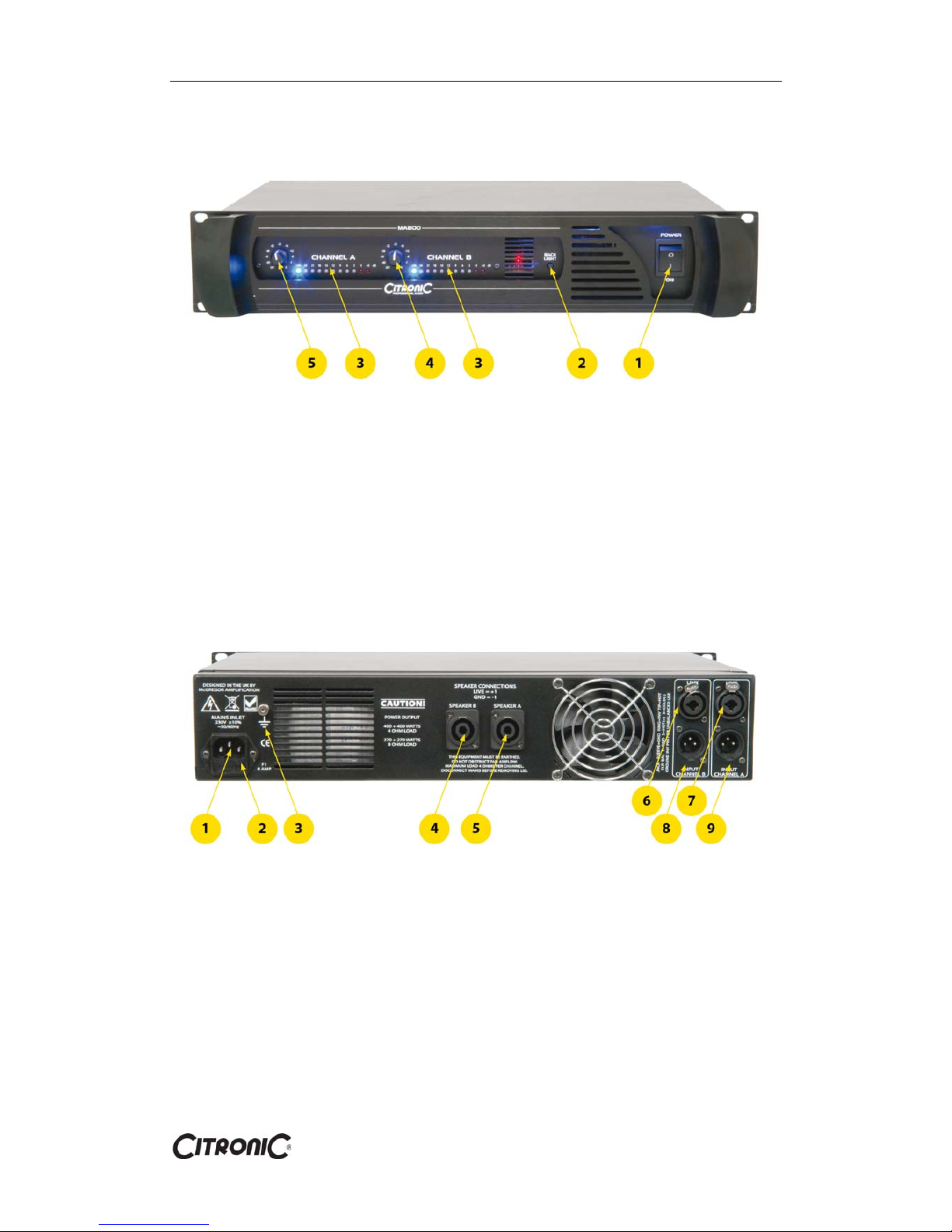
Front Panel
1) Mains Power switch on and off
2) LED Back light switch for full panel illumination
3) LED Display Master output
4) Gain control channel A
5) Gain control channel B
Rear Panel
1) IEC Power input socket
2) Fuse holder
3) Ground point for DJ mixers / players
4) Speaker output channel B
5) Speaker output channel A
6) Signal input combo (Balance/Unbalanced) for Channel B
7) Signal input combo (Balance/Unbalanced) for Channel A
8) Signal input 3 pin XLR Balanced for Channel B
9) Signal input 3 pin XLR Balanced for Channel A
Page 5

User Manual
171.231/234/237
5
Power supply
Supply voltage is 230Vac ±10%, 50-60Hz
A standard IEC mains inlet is fitted to all models and a power lead is supplied in the box. The IEC lead
connects between the inlet socket and a suitable mains supply. Please ensure you switch off the unit on
the front panel before turning the mains on or off at the wall.
Limiter
The amplifiers are fitted with internally adjustable limiters to protect speakers and reduce clipping
distortion. It is advisable to keep the limiter engaged at all times if this facility is available. Red LED's
will illuminate when the operator is driving the amplifier passed the clip point.
Installation
Each amplifier is 19” (483mm) Rack mountable. When mounting the amplifier into the rack, please
ensure that there is enough space around the amplifier to allow for good airflow and keep the amplifier
cool.
We recommend that you install the heaviest item on the bottom of the rack and the lightest towards the
top. Ensure 1U of space is left between each amplifier as the heat dissipates from the rear and bottom
panel.
Preventing or identifying interference
First of all, check that the amplifier is installed at a distance from industrial RF (radio frequency), radios,
tvs and mobile phones as these can cause noisy interference.
When installing components watch out for so-called ground loops, which could cause hum and
jeopardize the amplifier performance. The best way to avoid ground loops is to connect the electric
ground of all the equipment to a single central point.
 Loading...