

CITROËN DS3 R3 Max System User's Manual
System User Guide
1
DS3R3Max
System User Guide
2
Summary
1. Global System Overview ................(p3)
1. Looms ………………………………………….(p4)
2. Acquisition Signals ……………………...(p5)
2. Driver System Overview .................(p7)
1. Function Overview ……………………..(p8)
2. Steering Wheel Management ……(p9)
3. DashBoard Overview ………………..(p10)
4. Gearbox Management ……………..(p12)
5. Hydraulic System ……………………...(p14)
6. Accessory Management …………..(p16)
7. Start Assistance System ……………(p17)
8. Calibration ………………………………...(p18)
9. Diagnostics ………………………………..(p20)
3. Telemetry (Wintax) .........................(p21)
1. Install ……………………………………….…(p24)
2. Settings …………………………………..….(p25)
System User Guide - 03.12.14
1. Global System overview
3
System User Guide - 03.12.14
1.
Global System overview
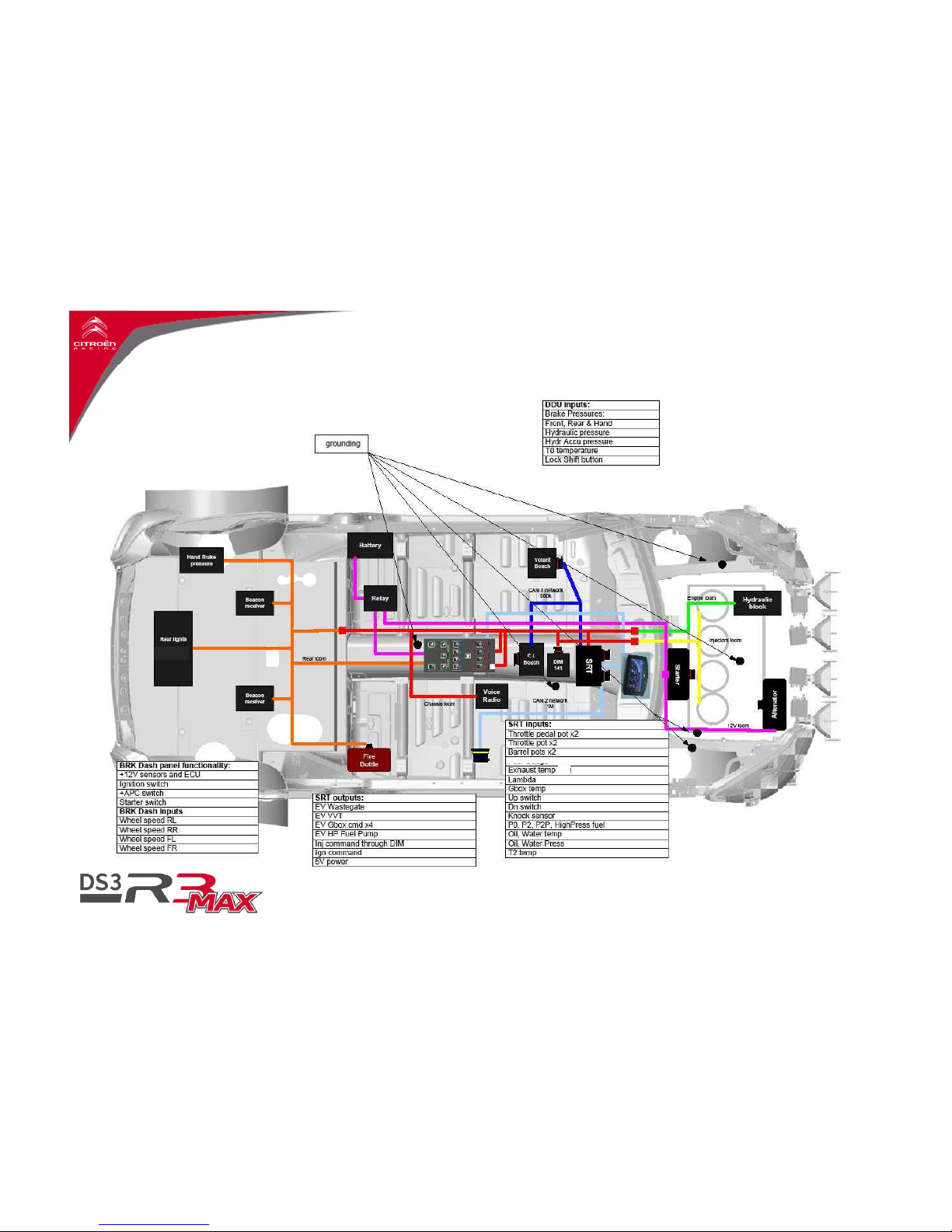
1. Looms
4
System User Guide - 03.12.14
(T4)
1.
Global System overview
2. Acquisition Signals
5
System User Guide - 03.12.14
Analog and frequency signals
These channels, dedicated to engine or chassis, are part of
the basic system. The processing done on them will be
realized by the ECU (calibration, diagnostics,…)
Engine oil pressure
Engine water pressure
Engine intake pressure
Engine turbocharger pressure
Atmospheric pressure
Barrel position
Pedal position(%)
Throttle position(°)
Clutch pressure
Hydraulic pressure
Wheels speed
Brake pressures
Knock sensor
Signals from Bosch modules
These channels, dedicated to chassis care are part of the
basic system. The processing done on them will be realized
by the Bosch unit (calibration, diagnostics,…)
XY accelerometer
Steering angle
Yaw
Signals from BRK
These channels dedicated to chassis care are part of the
basic system. The processing done on them will be realized
by the BRK unit (calibration, diagnostics,…)
Front Wheel speeds x2
Rear Wheel speeds x2
A specific signal will be sent to the trip meter
Temperature Processed signals
Four measurements of temperature are acquired by the ECU (Water Temp, Air Temp, Oil Temp, Gbox Temp and Box Temp).
These measurements are done through CTN temperature sensors ,specific type, therefore all the settings done into the
software are adapted to them. The use of a sensor other than the one specified can raise some doubts on the entire system,
anyway against the original setup.
6
Mandatory Sensors
Those sensors are used by the system, NOT having those working properly will generate
problems to system and parts:
Engine intake pressure (P2).
Engine turbocharger pressure (P2P).
Barrel position (Barrel).
Pedal position (Pedal).
Throttle position (Throttle).
Clutch pressure (P_CL).
Hydraulic pressure (P_Accu).
Wheel speeds (Wspeed_FL/FR/RL/RR).
Hand Brake pressure (P_HdBrk).
Engine water temperature (T_WAT).
Exhaust temperature (T4).
Intake temperature (T2).
Atmospheric pressure (P0).
Knock sensor (Deton_1/2/3/4).
System User Guide - 03.12.14
1.
Global System overview
2. Acquisition Signals
2. Driver System Overview
7
System User Guide - 03.12.14
2.
Driver
System Overview
1. Function Overview
8
System User Guide - 03.12.14
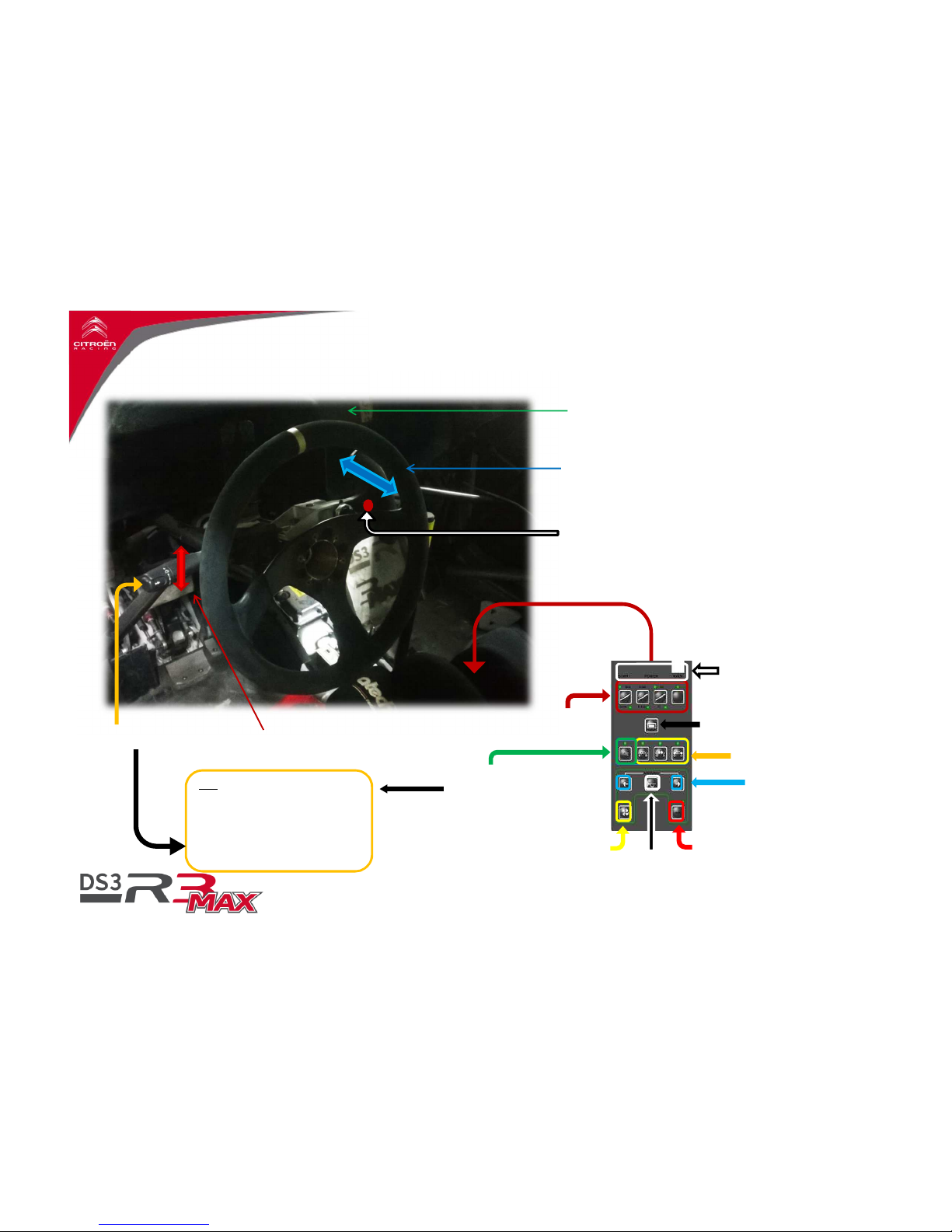
Strategy Mode
Auxilary Light Select
Headlights
1rtPress : Cornering Lamp
2ndPress : Low Beam
3rdPress : Switch off Lights
Horn
Aux Power // Fuel drain //
Steering Angle Zero
Turn Lights // Both
selected : Hazard lights
Scroll button
1 press : Scroll
Hold press : Swap Strd/Mechanic
Heater // Engine fans test
// Steering angle Zero
Nb: -
Corner lamp has to be
selected to use Fog lights at
least.
- High beam has to be
selected to use inner & outer
lights
Starter - Power - Main Switch
Located here
Low/High Beam // Flash
Wiper Speed
Dashboard Display
Gear Shift Paddle
Pull : Up
Push : Down
Gear shift lock (RN 1)
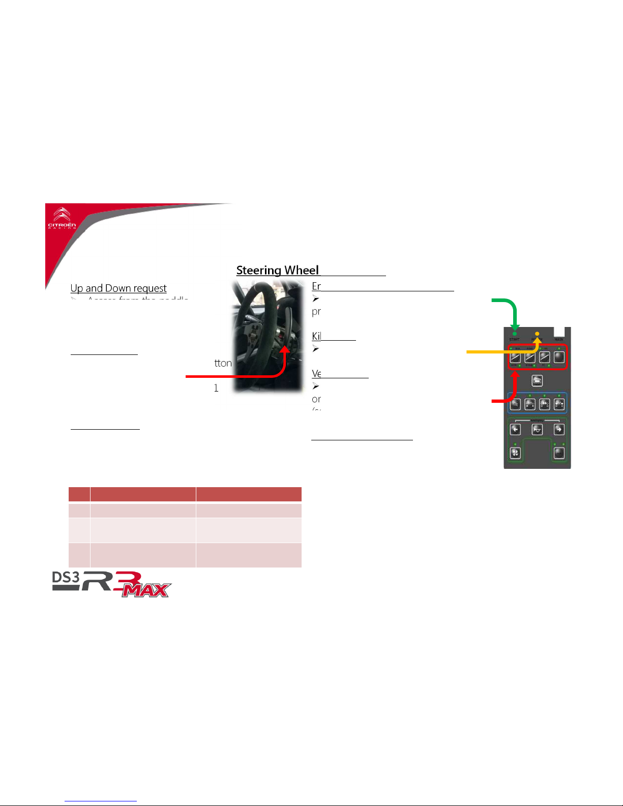
Up and Down request
Access from the paddle
Push to Downshift
Pull to Upshift
Neutral request
Active by pushing the lock button
and Up or Down request
Disable over 30km/h, gear > 1
And RPM > 2500
Reverse request
Active by pushing the lock button and Down
request
Disable over 10km/h or 2500rpm
Reverse disengaged by Neutral request.
Engine Crank (Oil pressure build)
Active if DIM141 is not connected by
pressing ‘start’ button
Kill Engine
Active if Power is switched OFF
Vehicle Maps
Few Vehicle maps will be available
on the center panel in STAGE mode only
(see chart opposite).
Start Assistance System
See page 17
2.
Driver System Overview
2. Steering Wheel Management
9
System User Guide - 03.12.14
Steering Wheel Input Signal
Tarmac Gravel
S0 Torque reduced (low grip) Torque reduced (low grip)
S1
Intermediate Torque
SAS (standard grip)
Intermediate Torque
SAS (standard grip)
S2
Full power
SAS (high grip)
Full power
SAS (high grip)
2.
Driver System Overview
3. Dashboard Overview
10
System User Guide - 03.12.14
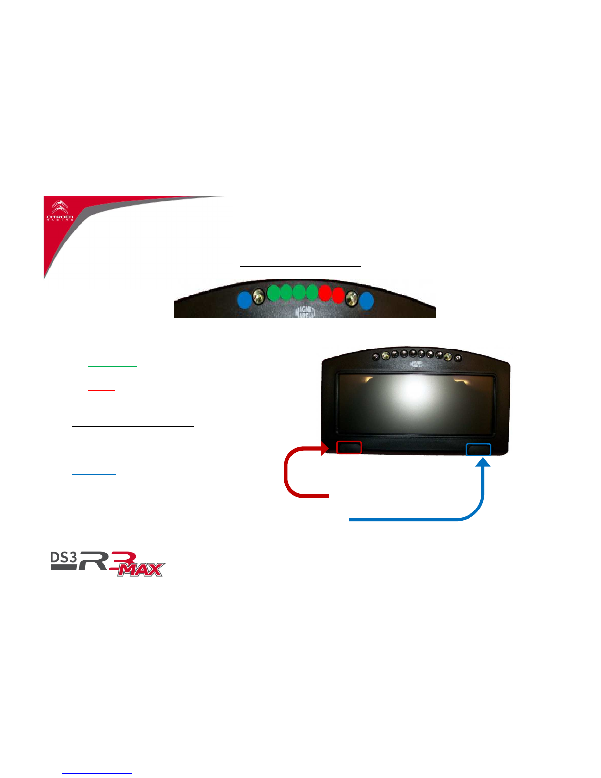
LED 1 /LED A/ LED B/ LED C/ LED D/ LED E/ LED F /LED 2
Revolution Information (if GDU is not installed)
LED A to D:
Engine’s approaching upshift rev
Lighted 1 by 1
LED E:
Ideal time to shift
LED F:
Over revolution
Mode and Alarm Information
Led 1 only
Blinking : Not used
Freeze : Information
Led 2 only
Blinking : Alarm medium level
Freeze : Alarm Low level
Both
Blinking : Start engaged or Alarm High Level
Freeze : Not Used
DashBoard Information
Dashboard buttons
P1
Zeroing fuel consumption
P2
Scroll pages

2.
Driver System Overview
3. Dashboard Overview
11
System User Guide - 03.12.14
Revolution Information
LED A&B flashing :
Engine’s approaching
up shift rev
LED A&B fixed :
Engine’s approaching up
shift rev
LED A&B fixed and C&D flashing :
Engine’s approaching up shift rev
LED A to D Green Fixed :
Ideal time to
shift
LED A to D Red Fixed:
Over revolution
LED A
/
LED B
/
LED C
/
LED D
LED
Mode and Alarm Informations
Led
Blinking : Not used
Fixed : Information or Alarm
GDU Information
The GDU gear display fitting is optional. It can be ordered at the Boutique Citroën Racing under the reference
DS3R3-S1C0.OPT.010
The fitting of the additional gear display unit implies a reprogramming of your ECU.
When the GDU is fitted, the LED A to F of the main display are disabled.
 Loading...