

Page 1

2002
CAR 050013
«The technical information contained in this document is intended for the exclusive use of the trained personnel of the
motor vehicle repair trade. In some instances, this information could concern the security and safety of the vehicle. The
information is to be used by the professional vehicle repairers for whom it is intended and they alone would assume full
responsibility to the exclusion of that of the manufacturer».
«The technical information appearing in this brochure is subject to updating as the characteristics of each model in the
range evolve. Motor vehicle repairers are invited to contact the CITROËN network periodically for further information and
to obtain any possible updates».
Page 2

PRESENTATION
THIS HANDBOOK summarises the specifications, adjustments, checks and special features of the CITROEN C8.
The handbook is divided into the following sections representing the main functions :
GENERAL - ENGINE - INJECTION - IGNITION - CLUTCH - GEARBOX - DRIVESHAFTS - AXLES - SUSPENSION - STEERING - BRAKES - HYDRAULICS ELECTRICAL - AIR CONDITIONING.
Page 3
GENERAL
1
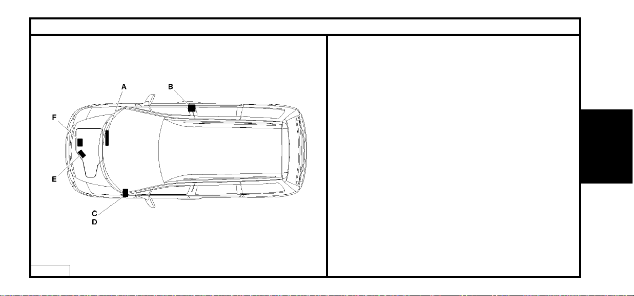
IDENTIFICATION OF VEHICLES
E1AP0A2D
(A) Chassis stamp (cold stamp on bodywork).
(B) Manufacturer’s data plate (under RH centre pillar).
(C) A-S / RP No. and RP paint code
(label on front pillar).
(D) Inflation pressures and tyre references.
(label on front pillar)
(E) Gearbox reference – Factory serial no.
(F) Engine legislation type – Factory serial no.
GENERAL
Page 4
2
GENERAL
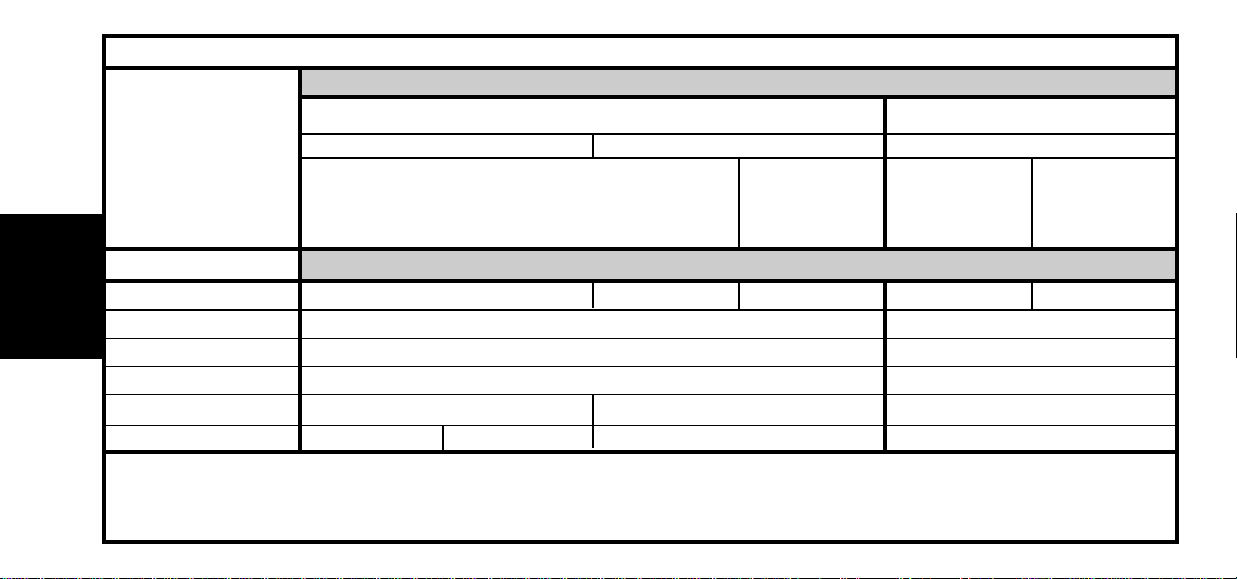
Emission standard IFL5
Type code EB RFNC/IF EB RFNF/IF EA RFNF/IF EB 3FZC/IF EA 3FZC/IF
Engine type RFN 3FZ
Cubic capacity (cc) 1998 2230
Fiscal rating (hp) 911
Gearbox type BE4/5 AL4 ML5C
Gearbox ident. plate 20 DL 27 (1) 20 DL 26 (2) 20 TP 74 20 LM 09
IDENTIFICATION OF VEHICLES
Petrol
2.0i 16V
2.2i 16V
X – SX
Exclusive
SX
Captain Chair
SX
Captain Chair
Exclusive
Captain Chair
Automatic
ManualManual
X - SX
(1) = Right hand drive
(2) = Left hand drive.
Page 5
3
GENERAL
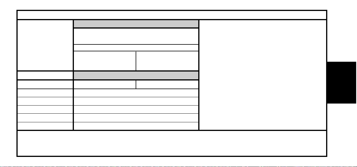
Automatic
Emission standard IFL5
Type code SEB XFWF/IF EA XFWF/IF
Engine type XFW
Cubic capacity (cc) 2946
Fiscal rating (hp) 14
Gearbox type 4 HP 20
Gearbox ident. plate 20 HZ 27
IDENTIFICATION OF VEHICLES
Petrol
3.0i V6 S24
Exclusive
Captain Chair
Exclusive
Page 6
4
GENERAL
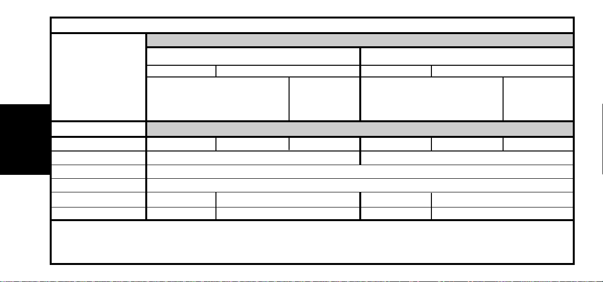
Emission standard L4
Type code EB RHTB EB RHTE EA RHTE EB RHWB EB RHWE EA RHWE
Engine type RHT RHW
Cubic capacity (cc) 1997
Fiscal rating (hp) 7
Gearbox type ML5C AL4 ML5C AL4
Gearbox ident. plate 20 LM 05 20 TS 04 20 LM 05 20 TS 04
IDENTIFICATION OF VEHICLES
Diesel
2.0 HDi (*)
2.0 HDi (**)
X – SX – Exclusive
SX
Captain Chair
Automatic
Manual AutomaticManual
SX
Captain Chair
X – SX – Exclusive
(*) = With particle filter.
(**) = Without particle filter.
Page 7
5
GENERAL
(*) = With particle filter.
Manual
Emission standard L4
Type code EB 4HWB EA 4HWB
Engine type 4HW
Cubic capacity (cc) 2179
Fiscal rating (hp) 8
Gearbox type ML5C
Gearbox ident. plate 20 LM 01
IDENTIFICATION OF VEHICLES
Diesel
2.2 HDi (*)
SX
Captain Chair
Exclusive
Captain Chair
SX
Captain Chair
Page 8
GENERAL SPECIFICATION: LIFTING AND SUPPORTING THE VEHICLE
6
GENERAL
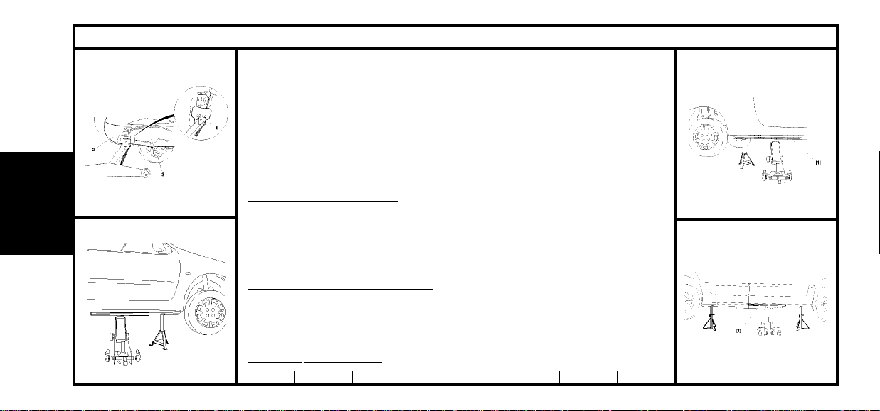
Tooling.
[1] Crossbeam : (-). 0010.
Front lifting on one side.
Position the jack (4) at the strongpoints provided for this purpose on each side
of the front crossmember between the bumper (2) and the engine (3).
Front central lifting.
Using a jack equipped with a crossbeam (sufficiently rigid) take the weight at the
two strongpoints on the front crossmember.
Side lifting.
At the front and at the rear
Take the weight at the sill, by means of the crossbeam [1], as close as possible
to the jacking point.
Position a stand at the jacking point provided for the purpose of lifting the
vehicle with the jack.
WARNING : Avoid the battery tray on the right hand side.
Side lifting at both front and rear
Take the weight at the sill, by means of the crossbeam [1].
Position stands at the jacking points provided for the purpose of lifting the
vehicle with the jack.
WARNING : Lifting at the rear of the vehicle using the crossbeam is
STRICTLY PROHIBITED.
E2AK02ZD E2AF006C E2AK030D E2AK031D
Page 9
7
GENERAL SPECIFICATION: LIFTING AND SUPPORTING THE VEHICLE
GENERAL
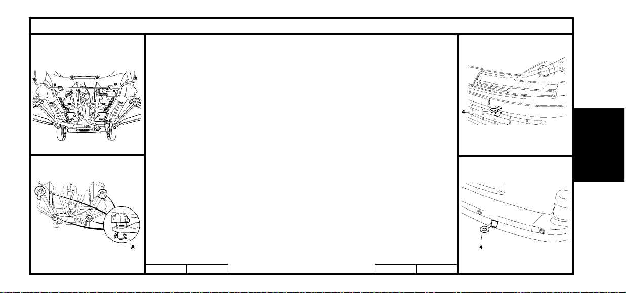
Lifting by means of a two-column workshop lift
WARNING : The removing of components such as the engine/gearbox, rear sub-
frame etc, can cause a displacement of the centre of gravity: Use a lift equipped
with retaining devices to keep the body stable on the lift.
Without body clamps.
Place the lift’s guide pads at each jacking point.
WARNING : To prevent any risk of the vehicle toppling, it is prohibited to
remove mechanical components.
With body clamps
WARNING : These clamps are fitted only on FOG lifts.
Position the clamps at the sill in the jacking points provided, screw heads oriented
towards the outside of the vehicle. Tighten the clamps using the gudgeon pin and,
after tightening, engage the pin in the hole (A).
Towing (front).
Lift the blank with the aid of the flat part of the towing eye (1) and then screw the
eye home.
NOTE : The towing eye is to be found on the front panel inside the engine compartment.
Towing (rear).
Lift the blank (1) and screw the towing eye home.
E2AF004D E5AF022D E2AK02YD E2AK02XD
Page 10
8
GENERAL
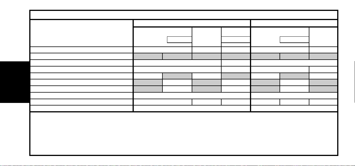
Engine type RFN 3FZ XFW RHT - RHW 4HW
Engine angle
Engine with filter change 4.25 5.25 4.75
Between Min. and Max. 1.7 2 1.9 1.5
5-speed gearbox 1.8 2 2 2
Automatic gearbox 6 8.3 6
After oil change 3 5.3 3
Hydraulic or brake circuit 0.66 0.66
Cooling system 7 7.2 10.5 10 10.2 11.3
Fuel tank capacity 80 80
CAPACITIES (in litres)
Petrol Diesel
Auto.
Auto. Auto.
2.0i 16V 2.2i 16V 3.0i 24V 2.0 HDi 2.2 HDi
Page 11

9
ENGINE SPECIFICATIONS
Diesel
Engines : RFN - 3FZ - XFW - RHW - RHT - 4HW
Petrol
All Types
2.0i 16V 2.2i 16V 3.0i 24V 2.0 HDi 2.2 HDi
Engine type
Cubic capacity (cc)
Bore / Stroke
Compression ratio
Power ISO or EEC KW - rpm
Power DIN (HP - rpm)
Torque ISO or EEC (m.daN - rpm)
RFN 3FZ XFW RHT- RHW 4HW
1997 2230 2946 1997 2179
85/88 86/96 87/82.6 85/88 85/96
10.8/1 10.9/1 17.3/1 17.6/1
100-6000 116-5650 150-6000 79-4000 94-4000
138-6000 160-5650 204-6000 109-4000 130-4000
19-4100 21.7-3900 28.5-3750 27-1750 31.4-2000
ENGINE
Page 12

10
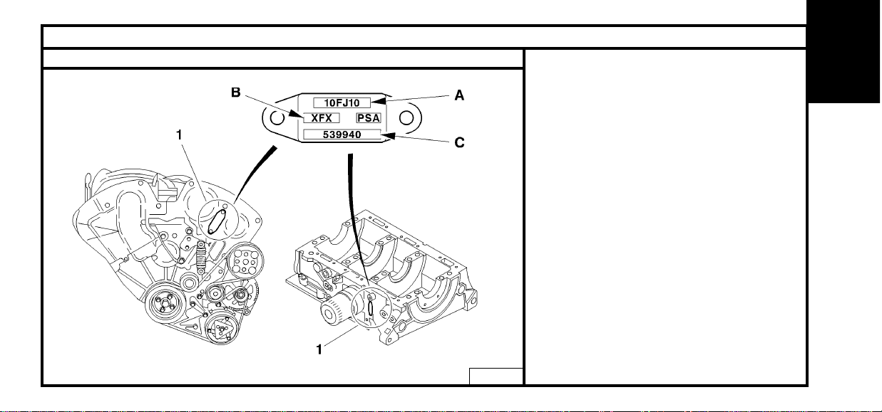
ENGINE SPECIFICATIONS
Engines : RFN – 3FZ
(1) Compulsory engine plate :
(A) Engine legislation type.
(B) Component reference.
(C) Factory serial no.
B1BB010D
ENGINE
Page 13
11
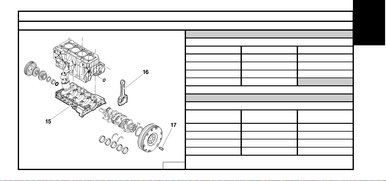
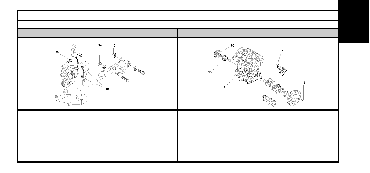
SPECIAL FEATURES : TIGHTENING TORQUES (m.daN)
Engines : RFN – 3FZ
Crankshaft
Crankshaft bearing cap cover (15)
Description M11 M6
Pre-tightening 1 ± 0.1 0.5
Slackening Yes No
Re-tightening 1 ± 0.1 puis 2 ± 0.2 1 ± 0.1
Angular tightening 70° ± 5°
B1BK1X8D
Description
(16) Con-rod caps
(17) Flywheel/
crankshaft fixing
Pre-tightening 1 ± 0.1 2.5 ± 0.2
Slackening Yes 18°± 1°
Re-tightening 2.5 ± 0.2 1 ± 0.1
22°±2°Angular tightening 46° ± 5°
ENGINE
Page 14
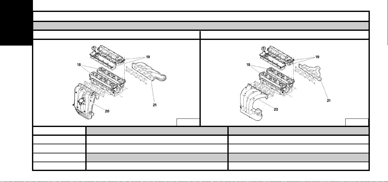
SPECIAL FEATURES : TIGHTENING TORQUES (m.daN)
Equipment on cylinder head
Engine : RFN Engine : 3FZ
12
B1BK1X9D B1BK1XAD
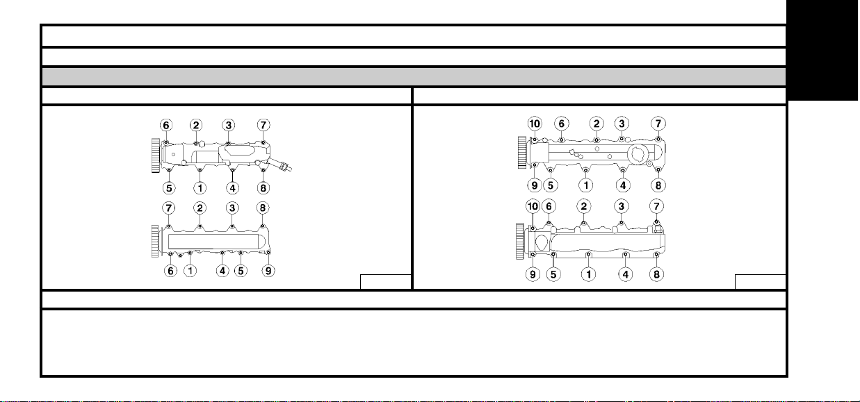
Description (18) Camshaft bearing cap covers (19) Valve covers
0.5 0.5
1 ± 0.1 1.5 ± 0.1
(20) Inlet manifold (21) Exhaust manifold
1 ± 0.1 3.5 ± 0.3
Pre-tightening
Tightening
Description
Tightening
ENGINE
Page 15
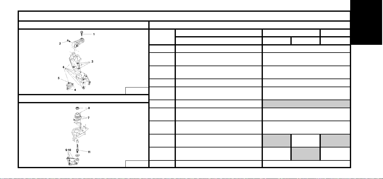
13
SPECIAL FEATURES: POWER UNIT SUSPENSION
Upper RH engine support Engines : RFN – 3FZ
Description RFN 3FZ
Gearbox type
Rod/body fixing screw..(1)
(2)
(3)
(4)
(5)
(6)
(7)
(8)
(9)
(10)
(11)
Engine support/torque reaction rod
flexible stop pin
Upper support/intermediate
support fixing screw.
Upper support/body fixing screw
Upper support/flexible
support fixing nut.
Support
LH flexible support/LH engine
support fixing nut.
LH flexible support/body
fixing screw.
Intermediate engine support/gearbox
casing fixing screw.
LH intermediate support/gearbox
fixing screw.
Flexible support pin.
BE4/5 AL4
5 ± 0.5
4.5 ± 0.4
6.5 ± 0.6
3 ± 0.3
4.5 ± 0.4
6.5 ± 0.6
3 ± 0.3
4.5 ± 0.4
5 ± 0.5
6 ± 0.6 4.5 ± 0.4
ML5C
Intermediate engine support
B1BK1X5D
B1BK1X6D
Ref.
ENGINE
Page 16
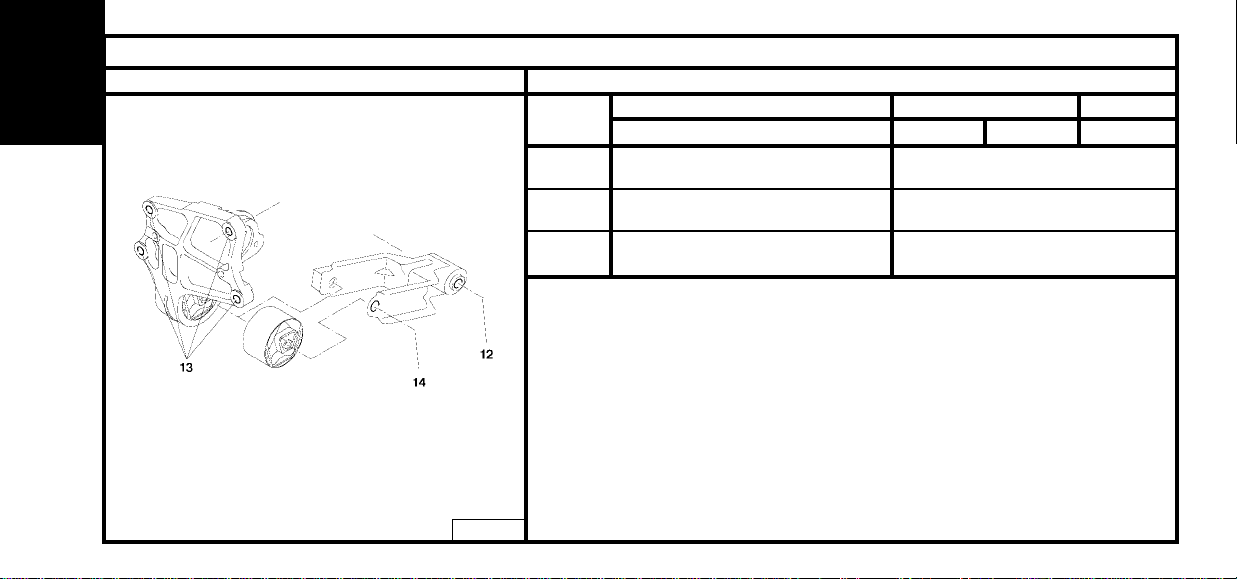
14
SPECIAL FEATURES: POWER UNIT SUSPENSION
Intermediate engine support Engines : RFN – 3FZ
Description RFN 3FZ
Gearbox type
(12)
(13)
(14)
Lower RH rod/subframe
fixing screw.
Lower RH engine support/cylinder
block fixing screw.
Lower rod/lower RH engine
support fixing screw
BE4/5 AL4
9 ± 0.9
4.5 ± 0.4
6.5 ± 0.6
ML5C
B1BK1X7D
Ref.
ENGINE
Page 17
15
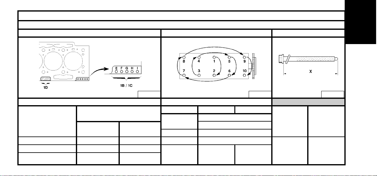
CYLINDER HEAD
Engines : RFN – 3FZ
Cylinder head gasket identification Cylinder head tightening (m.daN) Cylinder head bolts
(1D) : Manufacturer
identification.
Angular
tightening
Tightening
Slackening
Pre-tightening
285°
2
360°
2/ : 5
1/ : 1.5
3FZ
RFN
RFN
Tighten in the order indicated
X = MAXI re-usable
270°
(1C) : Repair dimension
E – F – H =0.99 E – F – G sans
E – H = 0.8 E – G = 0.8
RFN 3FZ
Cylinder head gasket thickness
(mm)
Ref.
Multi-layer metallic gasket.
(1B) : Nominal dimension
3FZ
144.5 mm 127.5 mm
B1BK24QD B1DK001C B1DB002C
ENGINE
Page 18
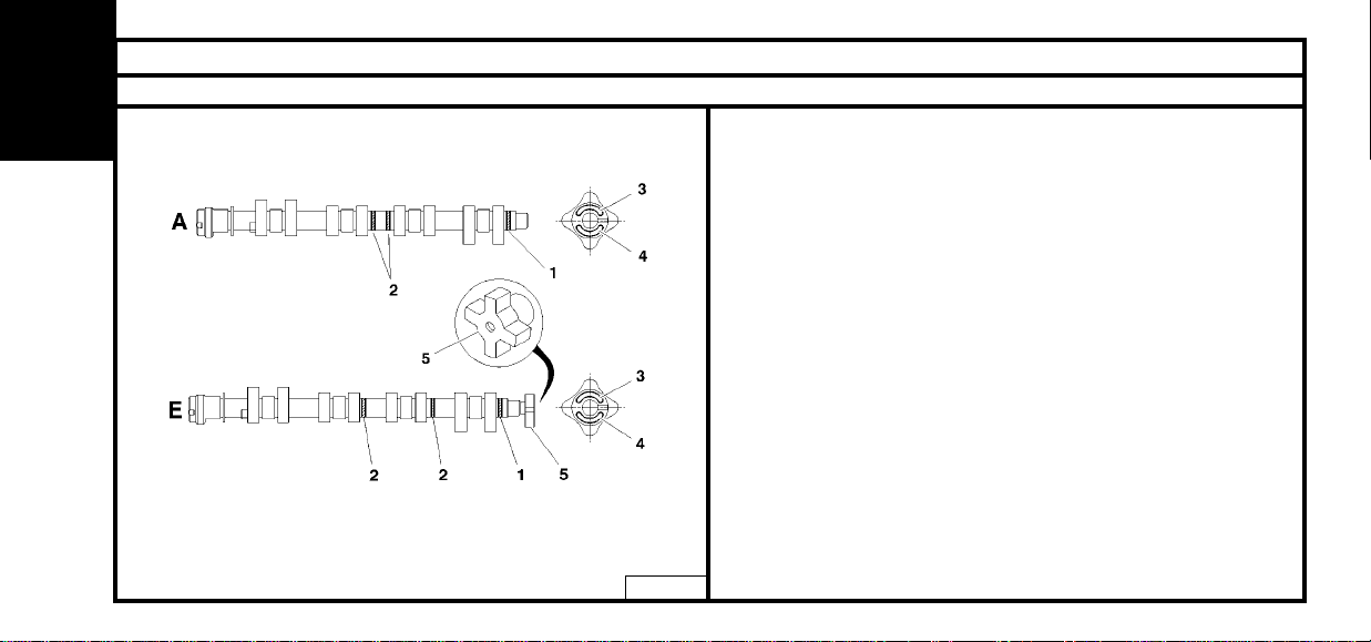
SPECIAL FEATURES: VALVE TIMING
Engines : RFN - 3FZ
The camshafts are referenced following two methods.
- (1) Marking position (2) Paint rings.
- (3) Marking position (4) Marking at end of shaft.
- (5) Target for camshaft position sensor.
Marking position:
(1) Paint ring : Repair reference.
(2) Green paint ring : Factory reference.
(3) Inlet D1309 : Exhaust D1348.
(4) Inlet 96 332 713 99 : Exhaust 96 3425433 99.
Timing belt.
Width : 25.4 mm
Number of teeth : 153
Material : HSN
Valve clearances when cold
Inlet (A) : NON adjustable
Exhaust (E) : NON adjustable
16
B1EK1UCD
ENGINE
Page 19
17
ENGINE SPECIFICATIONS
Engine : XFW
(A) Component reference.
(B) Engine legislation type.
(C) Factory serial no.
B1BK1JWD
ENGINE
Page 20

18
ENGINE
SPECIAL FEATURES : TIGHTENING TORQUES (m.daN)
Engine : XFW
Power unit suspension
Gearbox suspensionRH engine support (Suspension)
(2) Link rod fixing : 5 ± 0.5
(3) Link rod fixing : 4.5 ± 0.4
(4) Fixing of upper RH engine support on intermediate engine
support flexible mounting : 6 ± 0.6
(5) Fixing of RH engine support on flexible mounting : 4.5 ± 0.4
(6) Fixing of flexible mounting : 3 ± 0.3
(7) Fixing of RH intermediate engine support on cylinder block : 6 ± 0.6
(8) Fixing of gearbox support on LH flexible mounting : 6.5 ± 0.6
(9) Shaft : 6.5 ± 0.6
(10) Fixing of flexible mounting on support : 3 ± 0.3
(11) Fixing of flexible mounting support on body : 2.5 ± 0.2
(12) Fixing of flexible mounting support on body : 2.5 ± 0.2
B1BK24RD B1BK24SD
Page 21
19
SPECIAL FEATURES : TIGHTENING TORQUES (m.daN)
Engine : XFW
CrankshaftPower unit suspension – Engine support (Lower)
(13) Torque reaction link rod fixing : 9 ± 0.9
(14) Fixing of link rod on torque reaction flexible mounting : 6.5 ± 0.6
(15) Fixing of torque reaction flexible mounting : 4.5 ± 0.4
(16) Fixing of heat shield on torque reaction flexible mounting : 1 ± 0.1
(17) Bearing cap Tightening : 2 ± 0.2
+ Angular tightening : 74° ± 7°
(18) Timing pinion Tightening : 4 ± 0.4
+ Angular tightening : 80° ± 8°
(19) Fixing of starter gear support flange, plus crankshaft
converter support Tightening : 2 ± 0.2
Angular tightening : 60° ± 6°
(20) Accessory pulley on timing pinion : 2.5 ± 0.2
B1BK24TD B1BK24UD
ENGINE
Page 22
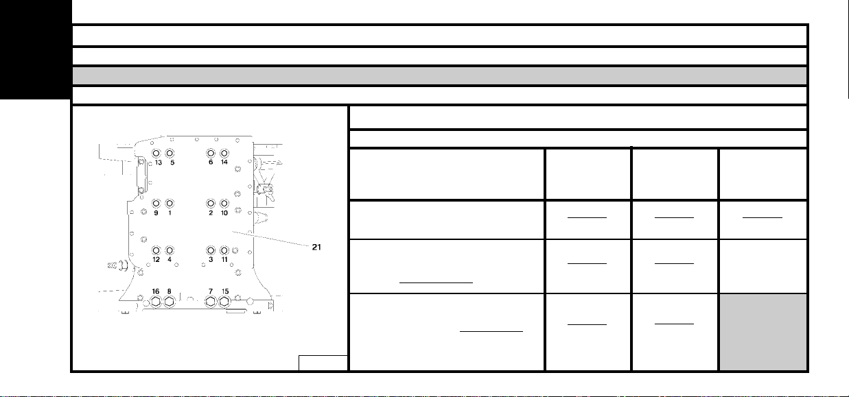
SPECIAL FEATURES : TIGHTENING TORQUES (m.daN)
Engine : XFW
Cylinder block
Bearing cap cover
Respect the sequence of stages and the order of tightening
Reference/description
(21) Fixings of bearings/cap covers or
bearings/caps
21) Fixings of bearings/cap covers or
bearings/caps
(Slacken to zero torque
.)
(21) Fixings of bearing cap cover or
bearing caps (Tighten bolt by bolt
)
Tightening
+ Angular tightening
M11
Bolts from 1
to 8
Stage 1
3 ± 0.3
Stage 2
1 ± 0.1
Stage 3
1 ± 0.1
Stage 4
YES
Stage 4
YES
Stage 5
3 ± 0.3
180°
Stage 6
1 ± 0.1
180°
NO
M8
Bolts from 9
to 16)
M6
20
B1BK24VD
ENGINE
Page 23
21
SPECIAL FEATURES : TIGHTENING TORQUES (m.daN)
Engine : XFW
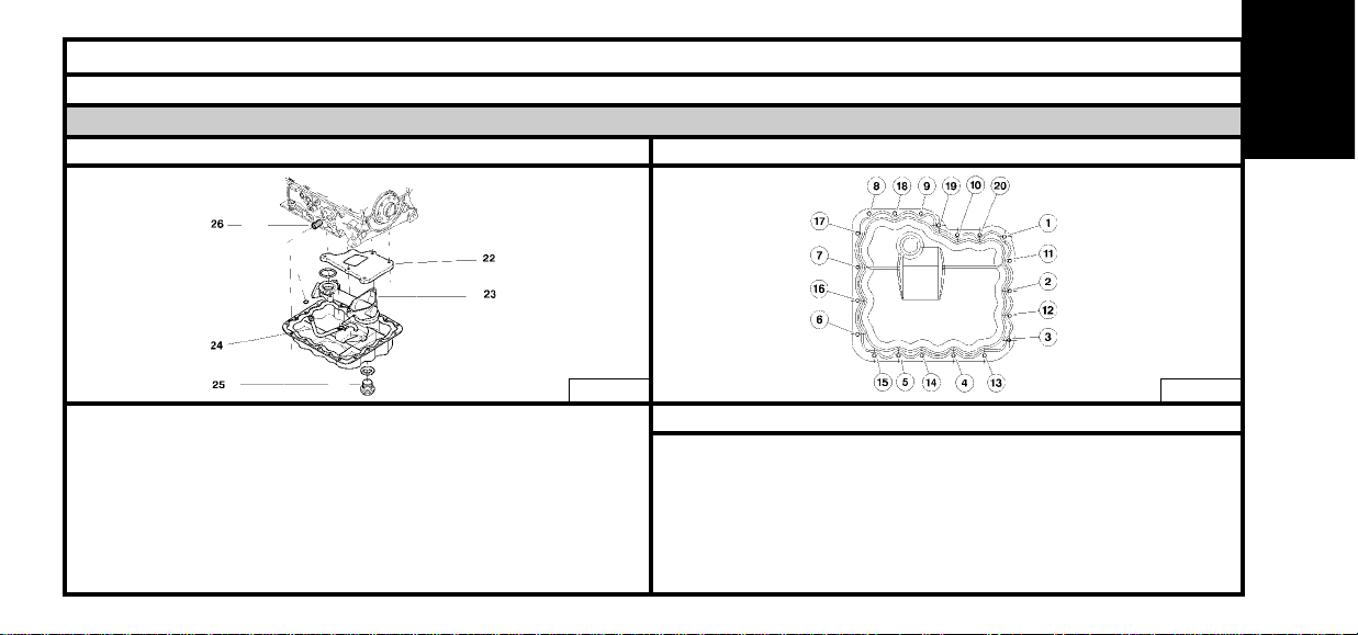
Lubrication circuit
Oil sumpLubrication circuit.
(22) Oil separator : 0.8
(23) Strainer : 0.8
(24) Induction pipe : 0.8
(25) Drain plug : 3 ± 0.3
(26) Oil filter sleeve (with coolant/oil exchanger) : 0.5
Oil filter : 0.2
Stage 1 : Do up bolts 13,15 and 17.
Stage 2 : Tighten bolts 13,15 and 17 to : 0.2
Stage 3 : Do up the 17 remaining bolts.
Stage 4 : Tighten the remaining bolts to : 0.5
Stage 5 : Tighten all the bolts : 0.8
Stage 6 : Repeat the tightening a few times in the same order to obtain
a tightening torque of 0.8 m.daN on all the bolts.
B1BK24WD B1BK24XD
ENGINE
Respect the sequence of stages and the order of tightening
Page 24
22
SPECIAL FEATURES : TIGHTENING TORQUES (m.daN)
Engine : XFW
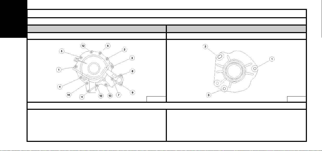
Cooling circuitLubrication circuit
Coolant pumpOil pump
Stage 1 : Position the screws and do them up by hand.
Stage 2 : Pre-tighten the screws : 0.5
Stage 3 : Tighten the screws : 0.8
Stage 4 : Repeat the tightening a few times in the same order to obtain
a tightening torque of 0.8 m.daN on all the screws.
Stage 1 : Position the screws and do them up by hand.
Stage 2 : Pre-tighten the screws : 0.5
Stage 3 : Tighten the screws : 0.8
Stage 4 : Repeat the tightening a few times in the same order to obtain a
tightening torque of 0.8 m.daN on all the screws.
B1BK3B6D B1BK3B7D
Respect the sequence of stages and the order of tightening
ENGINE
Page 25
23
SPECIAL FEATURES : TIGHTENING TORQUES (m.daN)
Engine : XFW
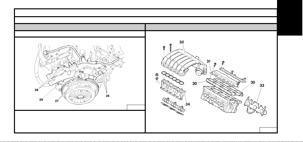
Cylinder head equipmentLubrication circuit
Coolant manifold
(27) Screws : 2.5 ± 0.2
(28) Screws : 0.8
(29) Screws : 0.8
B1BK24YD
B1BK24ZD
ENGINE
Page 26

24
SPECIAL FEATURES : TIGHTENING TORQUES (m.daN)
Engine : XFW
Cylinder head equipment
Camshaft bearing cap cover (left hand side)Camshaft bearing cap cover (right hand side)
(30) Camshaft bearing cap cover or camshaft bearing:
Pre-tighten to : 0.2
Tighten to : 1
B1EK0GCC B1BK3B8D
Respect the sequence of stages and the order of tightening
ENGINE
Page 27
25
SPECIAL FEATURES : TIGHTENING TORQUES (m.daN)
Engine : XFW
Cylinder head equipment
Valve covers (left hand side)Valve covers (right hand side)
(31) Valve cover :
Pre-tighten to : 0.5
Tighten to : 0.8
B1EK0GEC B1EK0GFC
Respect the sequence of stages and the order of tightening
ENGINE
Page 28
26
SPECIAL FEATURES : TIGHTENING TORQUES (m.daN)
Engine : XFW
Cylinder head equipment
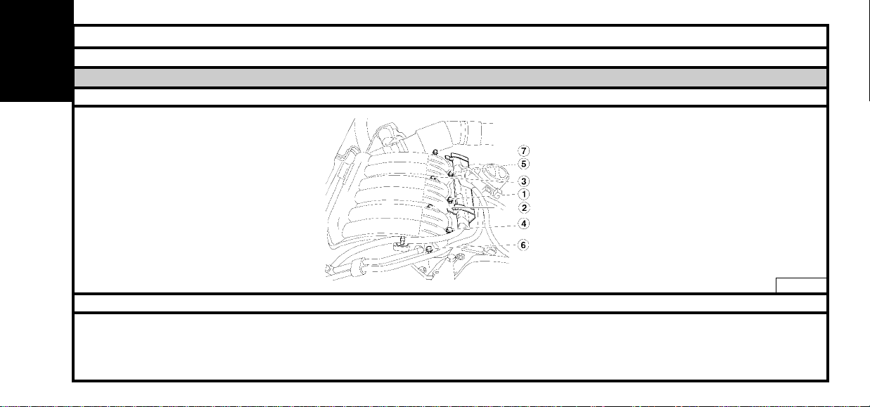
Inlet manifold
(32) Inlet manifold:
Pre-tighten to : 0.4
Tighten to : 0.8
B1BK251D
Respect the sequence of stages and the order of tightening
ENGINE
Page 29
27
SPECIAL FEATURES : TIGHTENING TORQUES (m.daN)
Engine : XFW
Cylinder head equipment
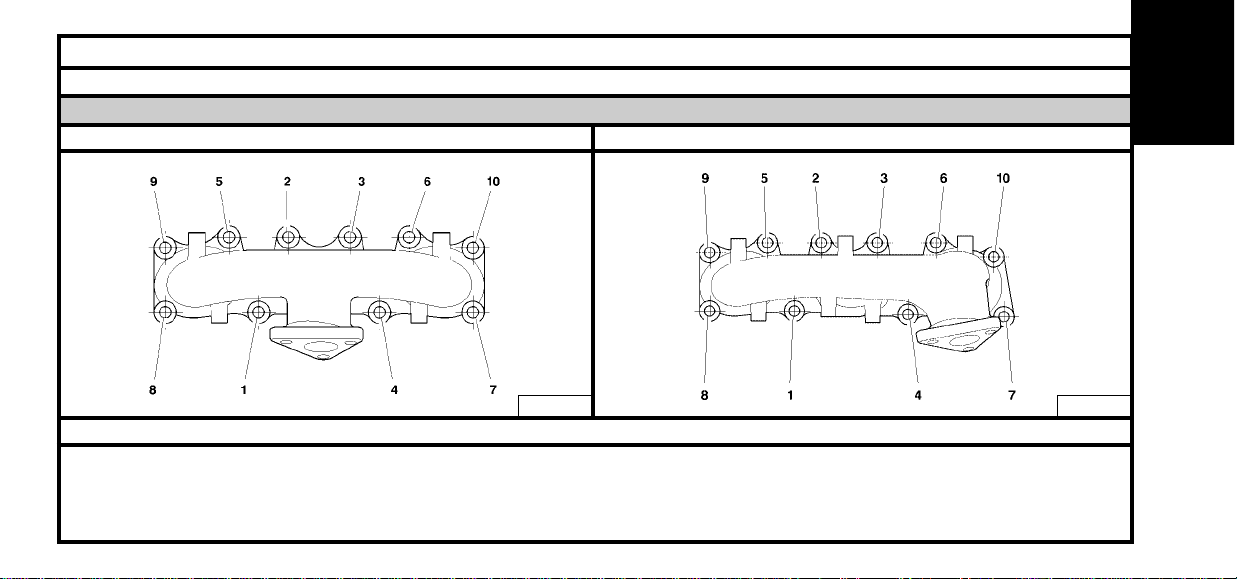
Exhaust manifold (left hand side)Exhaust manifold (right hand side)
(33) Exhaust manifold:
Pre-tighten to : 1
Tighten to : 3 ± 0.3
B1JK03ND B1JK03LD
Respect the sequence of stages and the order of tightening
ENGINE
Page 30

28
SPECIAL FEATURES : TIGHTENING TORQUES (m.daN)
Engine : XFW
Cylinder head equipment
Inlet distributor
(34) Inlet distributor:
Pre-tighten to : 0.4
Tighten to : 0.8
B1BK252D
Respect the sequence of stages and the order of tightening
ENGINE
Page 31

29
ENGINE
CYLINDER HEAD
Engine : XFW
Identification of cylinder head gaskets
The RH and LH cylinder head gaskets are specific, of multilayer metallic type.
Cylinder head gasket thicknesses
(1A) : Engine ref : G-H
(1B) : Nominal dimension: Without marking = 0.75 mm
(1C) : CRepair dimension : E (1st repair dimension R1) = 0.95 mm
(1C) : Repair dimension: E-F (2nd repair dimension R2) = 1.15 mm
(a) : RH cylinder head gasket.
(b) : LH cylinder head gasket.
V : Engine flywheel side.
B1DK0QKD B1DK0QLD
Respect the sequence of stages and the order of tightening
Page 32

B1DK0QPD
30
CYLINDER HEAD
Engine : XFW
Cylinder head tightening (m.daN) Cylinder head bolts
X = MAX. re-usable
Pre-tightening : 2
Slackening : YES
Tightening : 1.5
Angular tightening : 225°
NOTE : Grease the bolts on the
threads and under the heads,
using engine oil or Molykote G
plus).
149.5 mm
B1EK0XAD
ENGINE
Page 33

31
ENGINE
CYLINDER HEAD
Engine : XFW
Identification of camshafts
The camshafts are identified by the following references:
(1) Exhaust camshaft E389 (Front)
(2) Inlet camshaft. A423 (Front)
(3) Inlet camshaft. A422 (Rear)
(4) AExhaust camshaft E388 (Rear)
A=Inlet camshaft
E = Exhaust camshaft
B1EK0WVD
Timing belt
Width: 32 mm Number of teeth: 259
Page 34

32
CYLINDER HEAD
Engines : RHT – RHW - 4HW
Identification of cylinder head gasket Cylinder head tightening (m.daN) Cylinder head bolts
X = MAX. re-usable
Tighten in the order indicated
Pre-tightening : 1/ 2
2/ 6
Slackening : 360°
Tightening : 1/ 2
2/ 6
Angular tightening : 220°
B1DK1M6D
RHT - RHW 4HW
134 mm 134.5 mm
B1DK00SCB1DK0Q6C
ENGINE
NOTE : Grease the bolts on
the threads and under the
heads, using engine oil or
Molykote G plus).G Plus)
0.55 to 0.60 1.25 ± 0.04 0 1 1
0.61 to 0.65 1.30 ± 0.04 0 1 2
0.66 to 0.70 1.35 ± 0.04 0 1 3
0.71 to 0.75 1.40 ± 0.04 0 1 4
Piston
stand-proud
(mm)
Thickness
(mm)
RHT
RHW
4HW
Hole at
G
Hole at F
Page 35

33
ENGINE
AUXILIARY EQUIPMENT DRIVE BELT
Engines : RFN-3FZ
Tools
[1] Peg for dynamic tensioner roller (-).0189-E
Removing.
Remove:
The front RH wheel.
The front RH splash-shield.
Detension the auxiliary drive belt by actioning the screw (1).
Peg the dynamic tensioner roller (2), using tool [1].
Remove the auxiliary drive belt.
ESSENTIAL : Check that the rollers (3) and (4) turn freely (no tight spot).
Refitting.
Refit the auxiliary drive belt.
Check that the auxiliary drive belt is correctly positioned in the grooves of the various pulleys.
Remove tool [1].
Continue the refitting operations in reverse order to removal.
BXXK08DD
BXXK0AUD
Page 36

34
AUXILIARY EQUIPMENT DRIVE BELT
Engine : XFW
Tools
[1] Ratchet spanner FACOM (1/2" square).
[2] Reduction box FACOM S.230 (1/2" - 3/8" square).
Removing.
Move aside the power steering oil low pressure pipe flange.
Pivot the support (1) of the tensioner roller clockwise, as far as it will go, using tools [1] and [2].
Remove the auxiliary drive belt.
IMPERATIVE : Check the operation of the rollers (no play, no tight spot).
Refitting.
Position the auxiliary drive belt.
Commence with the crankshaft pulley (2).
Finish with the tensioner roller (3).
Free the support (1) of the tensioner roller, pivoting it anti-clockwise, using tools [1] and [2].
ESSENTIAL : Check that the belt is correctly positioned in the grooves of the various pulleys.
Continue the refitting operations in reverse order to removal.
B1EK0VAD
B1EK0VBD
ENGINE
Page 37

35
ENGINE
AUXILIARY EQUIPMENT DRIVE BELT
Engine : RHT - RHW
Tools.
[1] Tensioning lever : (-).0188-J2.
[2] Peg for dynamic roller Ø 4 mm : (-) 0188-Q1.
[3] Peg for dynamic roller Ø 2 mm : (-).0188-Q2.
[4] Dynamic roller compression lever : (-).1888-Z.
(A) Pegging hole.
(B) Belt wear check mark (fixed on engine).
(C) Zero wear mark.
(D) Maximum wear mark.
This marking system permits checking of the belt wear; if the marks (D) and (B) coincide, it implies that the belt
requires replacing.
Tighten the screw (1) to 4.5 ± 0.4 m.daN.
Removing
Remove:
- The front RH wheel.
- The front RH splash-shield.
- The under-engine shield.
IMPERATIVE : Mark the direction of rotation of the belt if to be re-used.
E5AK0E9C
B3EK0DHD
Page 38

36
AUXILIARY EQUIPMENT DRIVE BELT
Engine : RHT - RHW
Removing (continued).
Slacken the fixing (2).
Action the roller (3), using tool [1], until the tool [2] is positioned in the pegging hole (A).
Bring the roller (3) back towards the rear.
Gently tighten the screw (2).
Remove the belt.
ESSENTIAL : Check that the rollers (3) and (4) turn freely (no play, no tight spot).
Refitting.
IMPERATIVE: If re-using the belt, refit it respecting the direction of rotation marked on removal.
Refit the belt, finishing with the tensioner roller (4).
Action the roller (3), using tool [1] (clockwise) to free the tool [2].
Tighten the fixing (2) to 4.5 ± 0.5 m.daN, without altering the position of the roller.
ESSENTIAL : Check that the belt is correctly positioned in the grooves of the various pulleys.
Remove the tool [1].
Rotate the engine four times.
Check that the marks (B) and (C) coincide.
Tool [3] should be able to engage freely, if not, repeat the adjustment.
Complete the refitting.
B1BK1A4C
ENGINE
Page 39

37
AUXILIARY EQUIPMENT DRIVE BELT
Engine : 4HW
Tools.
[1] Peg for dynamic roller : (-) 0188-Q1
[2] Dynamic roller compression lever : (-).1888-Z.
(A) Pegging hole.
(B) Belt wear check mark (fixed on engine).
(C) Zero wear mark.
(D) Maximum wear mark.
This marking system permits checking of the belt wear; if the marks (D) and (B)
coincide, it implies that the belt requires replacing.
Tighten the screw (1) to 4.5 ± 0.4 m.daN.
Removing.
Remove:
- The front RH wheel.
- The front RH splash-shield.
- The under-engine shield.
IMPERATIVE : Mark the direction of rotation of the belt if to be re-used.
E5AK0EDC
E5AK0E8C
B3EK09PC
ENGINE
Page 40

38
AUXILIARY EQUIPMENT DRIVE BELT
Engine : 4HW
Removing (continued).
Action the roller (3), using tool [2], until the tool [1] is positioned in the pegging hole (A).
Remove the belt.
ESSENTIAL : Check that the rollers (3) and (4) turn freely (no play, no tight spot).
Refitting.
IMPERATIVE: If re-using the belt, refit it respecting the direction of rotation marked on removal.
Refit the belt, finishing with the tensioner roller (3).
ESSENTIAL : Check that the belt is correctly positioned in the grooves of the various pulleys.
Rotate the engine four times.
Complete the refitting.
B1BK1IWD
ENGINE
Page 41

39
ENGINE
Tools
BELT TENSION/SEEM UNITS CORRESPONDENCE TABLE
! 4099-T (C.TRONIC.105)
4122-T (C.TRONIC.105.5)
!
!
!
B1EP135D
Page 42

40
AUXILIARY EQUIPMENT DRIVE BELT
Engines : All Types Petrol and Diesel
TOOLS
Belt tension measuring instrument : 4122 - T .(C.TRONIC 105.5)
WARNING : If using tool 4099-T (C.TRONIC 105), refer to the correspondence table on page 39.
ESSENTIAL:
Before refitting the auxiliary equipment drive belt, check that:
- 1 / The roller(s) rotate freely (no play or stiffness)
- 2 / The belt is correctly engaged in the grooves of the various pulleys.
ENGINE
Page 43

41
ENGINE
CHECKING AND SETTING THE VALVE TIMING
Engine : RFN
Tools.
[1] Crankshaft setting peg : (-).0189-B
[2] Camshaft hub setting pegs : (-).0189-AZ
[3] Belt retaining pin : (-).0189-K
[4] Positioning peg : (-).0189-J
[5] Tool for immobilising hub : (-).6310-T
Removing.
Disconnect the battery.
Remove:
- The under-engine shield.
- The auxiliary drive belt (see corresponding operation).
Move aside:
- The fuel delivery pipe.
- The canister purge electrovalve.
- The expansion chamber.
Remove:
- The screws (1) and (2).
- The torque reaction rod (3).
- The screws (4), plus the auxiliary drive pulley.
- The timing covers (5) and (6).
WARNING : Do not slacken the fixing screws (A).
B1EK1UDD
B1EK1T7D
B1EK0V7D
Page 44

42
CHECKING AND SETTING THE VALVE TIMING
Engine : RFN
Removing (continued).
Peg :
- The camshafts, using tool [2].
- The crankshaft, using tool [1].
Slacken the screw (7) while holding tool [4].
Using the hexagonal recess (C), turn the eccentric hub (8) of the tensioner roller
(9) (clockwise), to detension the belt. The cursor (10) moves against the tool [4].
Remove the timing belt.
B1EK1UED
B1EK1UFD
ENGINE
Page 45

43
CHECKING AND SETTING THE VALVE TIMING
Engine : RFN
Refitting.
Systematically replace the timing belt.
IMPERATIVE : Check that the rollers (9) and (11), as well as the coolant pump (12) turn freely (no
tight spot).
When replacing the belt (11), tighten the fixing to 3.5 ± 0.3 m.daN.
Position the belt on the crankshaft pinion (13), respecting its direction of fitting.
Immobilise the belt, using tool [3].
Refit the timing belt, well-tensioned, in the following sequence:
- Guide roller (11).
- Pinions (14) and (15).
- Coolant pump (12).
- Tensioner roller (9).
B1EK1T8D
ENGINE
Page 46

44
CHECKING AND SETTING THE VALVE TIMING
Engine : RFN
Tensioning the timing belt.
Remove tool [3].
(D) : Max. position.
(E) : Nominal tension position.
Using the hexagonal recess (C), turn the roller hub (anti-clockwise), to bring the index (10) to position (D) to
tension the belt to the maximum.
Turn the eccentric hub (8) of the roller (9) (clockwise), to bring the cursor (10) into light contact with the peg [4].
IMPERATIVE : Never make a complete rotation of the eccentric hub (8) when tool [4] is in position.
NOTE : This operation places the index (10) in the nominal position (E).
Tighten the screw (7) to 2 ± 0.2 m.daN while holding the roller by means of the hexagonal recess (C).
Remove the pegs [1], [2] and [4].
Checks.
Make two rotations of the crankshaft (direction of rotation of the engine).
IMPERATIVE : Never turn the crankshaft backwards.
Make sure that the timing is correctly set, by refitting the pegs [1] and [2].
Remove the pegs [1] and [2].
Make ten rotations of the crankshaft (direction of rotation of the engine).
Check the position of the index (10).
If the tensioner index is not in its adjustment position (E), recommence the operations to tension the timing belt.
B1EK1T9D
B1EK1TAD
ENGINE
Page 47

45
CHECKING AND SETTING THE VALVE TIMING
Engine : RFN
Positioning the crankshaft.
NOTE : This operation positions all the pegs in their respective pegging points.
Peg:
- The camshaft pulleys, using tool [2].
- The crankshaft, using tool [1].
If this is not possible, reposition the flange (17).
IMPERATIVE : This operation guarantees the setting of the timing for subsequent operations.
Slacken the screw (16) so as to free the crankshaft pinion (17).
Bring the flange (17) to the pegging point, using tool [5].
Position tool [1].
Tightening of screw (16) (Tool FACOM D360).
Tighten to : 4 ± 0.4 m.daN
Angular tighten to : 53°±5°.
Remove tools [1], [2] and [5].
IMPERATIVE : When tightening screw (16), hold the pulley (17) in position, using tool [5].
B1EK1TBD
B1EK1TCD
ENGINE
Page 48

46
CHECKING AND SETTING THE VALVE TIMING
Engine : RFN
Refitting (continued).
Refit:
- The timing cover (6).
- The auxiliary drive pulley.
- The screws (4), tighten to 2.1 ± 0.2 m.daN.
- The timing cover (5).
- The torque reaction rod (3).
- The screws (1) and (2), tighten to 4.5 ± 0.4 m.daN.
Refit the auxiliary drive belt (see corresponding operation).
Continue the refitting operations in reverse order to removal.
B1EK0V7D
B1EK1T7D
ENGINE
Page 49

47
CHECKING AND SETTING THE VALVE TIMING
Engine : 3FZ
Tools.
[1] Crankshaft setting peg : (-).0189-B
[2] Exhaust camshaft setting peg : (-).0189-AZ
[3] Inlet camshaft setting peg : (-).0189-L
[4] Positioning peg : (-).0189-J
[5] Tool for immobilising hub : 6310-T
[6] Belt retaining pin : (-).0189.K
[7] Engine support crossmember : 4090-T
Removing.
Disconnect the battery.
Remove:
- The under-engine shield.
- The auxiliary drive belt (see corresponding operation).
Uncouple the exhaust line (to avoid damaging the flexible pipe).
Position the tool [7].
Move aside:
- The fuel delivery pipe.
- The canister purge electrovalve.
- The expansion chamber.
B1EK0V1D
B1EK1SJD
B1EK1SLD
ENGINE
Page 50

48
CHECKING AND SETTING THE VALVE TIMING
Engine : 3FZ
Remove:
- The screws (1) and (2).
- The torque reaction rod (3).
- The nut (4).
- The 3 screws (5).
- The RH engine support (6).
- The screws (7), plus the auxiliary drive pulley.
- The timing covers (8) and (9).
WARNING : Do not slacken the fixing screws (A).
IMPERATIVE : Do not slacken the fixing screws (B).
Peg:
- The exhaust camshaft, using tool [2].
- The inlet camshaft, using tool [3].
- The crankshaft, using tool [1].
B1EK1SUD
B1EK1SKD
B1EK1SMD
ENGINE
Page 51

49
CHECKING AND SETTING THE VALVE TIMING
Engine : 3FZ
Position tool [4].
Slacken the screw (10) while holding tool [4].
Using the hexagonal recess (D), turn the eccentric hub (11) of the tensioner roller (12) (clockwise), to detension
the belt. The cursor (13) moves against the tool [4].
Remove the timing belt.
Refitting.
Systematically replace the timing belt.
IMPERATIVE : Check that the rollers (12) and (14), as well as the coolant pump (15) turn freely (No play,
no tight spot).
When replacing the belt (14), tighten the fixing to 3.5 ± 0.3 m.daN.
Position the belt on the crankshaft pinion (16), respecting its direction of fitting.
Immobilise the belt, using tool [6].
Refit the timing belt, well-tensioned, in the following sequence:
- Guide roller (14).
- Pinion (17).
- Pinion (18).
- Coolant pump (15).
- Tensioner roller (12).
B1EK1SMD
B1EK1SND
ENGINE
Page 52

50
CHECKING AND SETTING THE VALVE TIMING
Engine : 3FZ
Tensioning the timing belt.
Remove tool [6].
(E) : Max. position.
(F) : Nominal tension position.
Using the hexagonal recess (D), turn the roller hub (anti-clockwise), to bring the index (13) to position (E) to tension the belt to the maximum.
Turn the excentric hub (11) of the roller (12) (clockwise), to bring the cursor (13) into light contact with the tool [4].
IMPERATIVE : Never make a complete rotation of the eccentric hub (11) when tool [4] is in tension.
NOTE : This operation places the index (13) in the nominal position (F).
Tighten the screw (10) to 2 ± 0.2 m.daN while holding the roller by means of the hexagonal recess (D).
Remove the tools [1], [2], [3], and [4].
Checks.
Make two rotations of the crankshaft (direction of rotation of the engine).
IMPERATIVE : Never turn the crankshaft backwards.
Make sure that the timing is correctly set, by refitting the camshaft and crankshaft setting pegs.
Remove the pegs.
Make ten rotations of the crankshaft (direction of rotation of the engine).
Check the position of the index (13).
If the tensioner index is not in its adjustment position (F), recommence the operations to tension the timing belt.
B1EK1SPD
B1EK1SQD
ENGINE
Page 53

51
CHECKING AND SETTING THE VALVE TIMING
Engine : 3FZ
Positioning the crankshaft.
NOTE : This operation positions all the pegs in their respective pegging points.
Peg:
- The inlet camshaft pulley, using tool [3].
- The crankshaft, using tool [1].
If this is not possible, reposition the flange (20).
IMPERATIVE : This operation guarantees the setting of the timing for subsequent operations.
Immobilise the crankshaft, using tool [5].
Slacken the screw (19) so as to free the crankshaft pinion (16).
Bring the flange (20) to the pegging point, using tool [5].
Position tool [1].
Tightening of screw (19) (Tool FACOM D360).
Tighten to : 4 ± 0.4 m.daN
Angular tighten to : 53°±5°.
Remove tools [1], [3] and [5].
B1EK1SRD
B1EK1SSD
ENGINE
Page 54

52
CHECKING AND SETTING THE VALVE TIMING
Engine : 3FZ
B1EK1STD
B1EK1SUD
ENGINE
Refitting (continued).
Refit:
- The timing cover (9).
- The auxiliary drive pulley.
- The screws (7), tighten to 2.1 ± 0.2 m.daN.
- The timing cover (8).
- The RH engine support (6).
- The torque reaction rod (3).
Tighten:
- Screws (5) to 6 ± 0.6 m.daN
- Nut (4) to 4.5 ± 0.4 m.daN
- Screws (1) and (2) to 4.5 ± 0.4 m.daN
Refit the auxiliary drive belt (see corresponding operation).
Continue the refitting operations in reverse order to removal.
Page 55

53
CHECKING AND SETTING THE VALVE TIMING
Engine : XFW
Tools.
[1] Camshaft setting pegs : (-).0187-B
[2] Crankshaft setting peg : (-).0187-A
[3] Belt retaining pin : (-).0187-J
[4] Peg for checking camshaft settings : (-).0187-CZ
[5] Tool for immobilising inlet camshaft hubs : (-).0187-C
[6] Tool for immobilising exhaust camshaft hubs : (-).0187-F
[7] Instrument for measuring belt tension : (-).0192
Removing.
Remove:
The front RH wheel
The RH wheelarch.
The front RH tie-bar.
The auxiliary drive belt (see corresponding operation).
The tensioner roller assembly (1).
The crankshaft pulley (2).
Support the engine using a stand.
Remove:
The upper RH torque reaction rod.
The RH engine support.
B1EK004D
ENGINE
Page 56

54
CHECKING AND SETTING THE VALVE TIMING
Engine : XFW
Removing (continued).
Remove:
The twelve screws (3) (6 mm external hexagonal adaptor).
The seven screws (4) (7 mm external hexagonal adaptor).
The two covers (5).
The cover (6).
The fixing screws of the power steering pump, then suspend the latter.
The support (7).
NOTE : The camshaft pegging operation can be performed without slackening the
pinion screws or rotating the camshafts (using tools [5] and [6]; lightly oil the pegs
[1] and [2] prior to fitting.
Peg in the sequence:
Camshafts, using tool [1].
Crankshaft, using tool [2].
B1EK005D
B1EK006D
B1EK007D
ENGINE
Page 57

55
CHECKING AND SETTING THE VALVE TIMING
Engine : XFW
Removing (continued).
Remove screw (8).
Slacken screws (9) and (10) and nut (11).
Pivot the tensioner roller eccentric (clockwise), using tool FACOM R 161 at «B».
Remove the guide roller (12).
Remove the timing belt, commencing with the tensioner roller and the coolant pump.
Refitting.
Make sure that the camshafts, as well as the crankshaft, are correctly pegged.
Check that the rollers (13) and (14), as well as the coolant pump (15) turn freely (no tight
spots).
If replacing the belt, tighten the rollers (13) and (14) to 8 ± 0.8 m.daN.
Slacken screws (16) by a 1/4 turn.
Ensure that the camshaft pinions rotate freely on their hubs.
Turn the four camshaft pinions (clockwise), to end of slots.
Engage the timing belt on the crankshaft pinion.
Immobilise the belt, using tool [4].
B1EK009D
B1EK008D
ENGINE
Page 58

56
CHECKING AND SETTING THE VALVE TIMING
Engine : XFW
Refitting (continued).
Position the belt on the guide roller (13), belt at (C) well tensioned.
NOTE : Carefully turn the camshaft pinion in the opposite direction to the rotation of the
engine in order to engage the belt on the pinion.
Engage the belt on the LH exhaust camshaft pinion (17).
IMPERATIVE : The angular displacement value of the pinion relative to the timing
belt should not be greater than the width of one tooth.
Engage the belt on the LH inlet camshaft pinion (18), as before.
Refit the roller (12), tighten to 8 ± 0.8 m.daN.
B1EK00BD
B1EK00AD
ENGINE
Page 59

57
CHECKING AND SETTING THE VALVE TIMING
Engine : XFW
Refitting (continued).
Engage the belt on:
The roller (13).
The camshaft pinions, inlet (19) then RH exhaust (20), as before for the camshafts.
Simultaneously engage the belt on:
The roller (21).
The pump (15).
The roller (14).
Using tool FACOM S.161, at «A», pivot the plate to be able to engage the screw (8).
Tighten screws (8), (9) and (10) to 2.5 ± 0.2 m.daN.
Pivot the tensoner roller to tension the belt to the maximum (anti-clockwise), using tool FACOM R.161 at «B» :
- SEEM CTI 901-1 : 440 ± 15 SEEM units,
- SEEM CTG 105.5 : 83 ± 2 SEEM units,
- SEEM CTG 105.6 : 86 ± 2 SEEM units.
Tighten the nut (11) of the tensioner roller to 1 ± 0.1 m.daN.
IMPERATIVE : Check that the camshaft pinions are not at end of slots (by removing a screw).
If they are, repeat the operation to refit the belt.
B1EK00CD
B1EK00DD
ENGINE
Page 60

58
CHECKING AND SETTING THE VALVE TIMING
Engine : XFW
B1EK0VRD
B1EK00ED
ENGINE
Refitting (continued).
Tighten at least two screws (16) per hub to 1 ± 0.1 m.daN, in the order indicated (17),(18),
(19) and (20).
Remove tools [4], [7], [1] and [2].
Effect two rotations of the crankshaft (direction of rotation of the engine).
WARNING : Never rotate the engine backwards.
Peg the crankshaft, using tool [2].
Slacken the nut (11) a 1/4 turn.
Align the marks (D) and (E) of the tensioner roller, using tool FACOM R.161.
Tighten the nut (11) to 2.5 ± 0.2 m.daN, without altering the position of the roller.
Remove the crankshaft setting peg [2].
Effect two rotations of the crankshaft.
WARNING : Never rotate the engine backwards.
Peg the crankshaft, using tool [2].
Check the position of the tensioner roller.
If the marks are not aligned, recommence the alignment of the marks (D) and (E) of the
tensioner roller.
Page 61

59
CHECKING AND SETTING THE VALVE TIMING
Engine : XFW
B1EK00HD
B1EK00GD
Refitting (continued).
Peg the camshaft hubs, starting with LH exhaust (17) then (18), (19) and (20), using tool
[1], proceeding in the following way:
- The peg goes in: slacken by 45° the fixing screws of the pinion on the camshaft hub,
- The peg does not go in: slacken by 45° the fixing screws of the pinion on the camshaft
hub until the peg will go in.
ESSENTIAL : Check that the camshaft pinions are not at end of slots (by removing
a screw).
If they are, repeat the operation to refit the belt.
Tighten the pinions in the sequence below:
Pinions (17), (18), (19), (20) tighten to 1 ± 0.1 m.daN.
Remove tools [1] and [2]
Checking the setting of the timing.
Effect two rotations (Normal direction of rotation of the engine).
IMPERATIVE : Never turn the engine backwards.
Refit the crankshaft peg [2].
Check that the peg for checking the camshaft settings [4] engages freely in the cylinder
heads (J), as far as the camshaft pinions.
ENGINE
Page 62

60
CHECKING AND SETTING THE VALVE TIMING
Engine : XFW
B1EK00JD
ENGINE
Checking the setting of the timing (continued).
Should this not be the case, repeat the operation to refit the belt.
Remove the crankshaft peg [2].
Refitting (continued).
Refit:
The power steering pump.
The support (7).
The tensioner roller assembly (1).
Tighten:
Screw (22) to 2.5 m.daN + LOCTITE FRNETANCH.
Screw (23) to 4.0 m.daN + LOCTITE FRNETANCH.
Screw (24) to 2.5 m.daN + LOCTITE FRNETANCH.
Screw (25) to 6.0 m.daN + LOCTITE FRNETANCH.
Tighten the crankshaft pulley screws to 2.5 ± 0.2 m.daN.
Refit the auxiliary drive belt (see corresponding operation).
Complete the refitting operations in the opposite order to removal.
Page 63

61
CHECKING AND SETTING THE VALVE TIMING
Engines : RHT-4HW
Tools :
[1] Instrument for measuring belt tension SEEM C.TRONIC : (-).0192
[2] Crankshaft setting peg (engine DW12TED4) : (-).0188-X
[3] Camshaft peg : (-).0188-M
[4] Belt retaining pin : (-).0188-K
[5] Engine flywheel stop : (-).0188-F
[7] Tensioning lever : (-).0188-J2
[8] Pulley extractor : (-).0188-P
[9] Crankshaft setting peg (engine DW10ATED4) : (-).0188-Y
[10] Crossmember : 4090-T
[11] Tie-bar support : 4176-T
[12] Retaining support : (-).0911-J
[13] Support with adjustable screw : (-).0911-H
[14] Set of plugs : (-).0188-T
Removing.
Remove:
- The front RH splashshield.
- The under-engine shield.
- The auxiliary drive belt (see corresponding operation).
ENGINE
Page 64

62
CHECKING AND SETTING THE VALVE TIMING
Engines : RHT-4HW
Removing.
Remove:
- The closing panel of the clutch casing (block the engine flywheel, tool [5]).
- The auxiliary drive pulley screw.
Refit the screw without the washer.
Remove:
- The auxiliary drive pulley, using tool [8].
- The tool [5].
Turn the crankshaft.
Peg:
- The engine flywheel, tool [2] (engine DW12TED4).
- The engine flywheel, tool [9] (engine DW10ATED4).
B1EK0TVC
B1EK1T4D
B1EK0TUC
ENGINE
Page 65

63
CHECKING AND SETTING THE VALVE TIMING
Engines : RHT-4HW
Removing (continued).
Disconnect the battery.
Move aside the header tank.
Position the tools for supporting the engine [10], [11], [12] and [13].
Remove:
- The scuttle panel grille.
- The torque reaction rod (1).
- The fuel unions (2).
IMPERATIVE : Plug the apertures using tool [13].
Protect the radiator harness with strong cardboard cut out to the dimensions of the radiator.
Remove:
- The RH engine support (4).
- The timing covers (3).
- The lower timing cover.
Peg the camshaft pulley, using tool [3].
Slacken the tensioner roller fixing (5).
Retighten the fixing to the position of maximum de-tension. (Tighten to 0.1 m.daN).
Remove the timimg belt.
B1EK1TTD
B1EK1T2D
ENGINE
Page 66

64
CHECKING AND SETTING THE VALVE TIMING
Engines : RHT-4HW
Refitting.
IMPERATIVE : Check that the rollers (5) and (6) as well as the coolant pump (7) turn freely (no play, no tight
spot), check also that these rollers are not noisy and/or that they are not throwing out grease.
In the event of replacement, tighten the roller (6) to 4.3 ± 0.4 m.daN.
Slacken the screws (8).
Check that the pulley (9) turns freely on its hub.
Tighten the screws (8) by hand.
Slacken the screws (8) by a 1/6 turn.
Turn the pulley (9) (clockwise), to end of slots.
Refit the timing belt, well tensioned, in the following order:
- Crankshaft (immobilise the belt, using tool [4]).
- Guide roller (6).
Engage the timing belt on the pulley (10).
Carefully turn the camshaft pinion in the opposite direction to the rotation of the engine in order to engage the belt
on the pinion.
WARNING : The angular displacement «a» of the pulley relative to the belt should not be greater than the width of
one tooth.
Engage the belt on the tensioner roller (5) and on the coolant pump pinion (7).
Turn the tensioner roller (5) (anti-clockwise), so as to put the tensioner roller (5) in contact with the belt.
Pre-tighten the fixing screw of the tensioner roller to 0.1 m.daN.
Remove the tool [4].
B1EK0TXC
B1EK0TYC
ENGINE
Page 67

65
CHECKING AND SETTING THE VALVE TIMING
Engines : RHT-4HW
B1EK1TSD
Pre-tensioning the timing belt.
Position the tool [1].
NOTE : Check that the tool is not in contact with anything else around it.
Turn the roller (5) (anti-clockwise), using tool [7] to obtain a tension of:
98 ± 2 SEEM units.
Tighten the screw (11) to 2.3 ± 0.2 m.daN (without modifying the position of the roller).
Remove the tool [1].
IMPERATIVE : By removing one of the screws (8) on the pulley (9), make sure that
these screws (8) are not at end of slots. (If they are, repeat the operation to refit the
timing belt).
Bring the screws (8) into contact with the pulleys.
Tighten the screws (8) to 2 ± 0.2 m.daN.
Remove the setting pegs [3] and [2].
Effect eight turns of the engine in the normal direction of rotation.
IMPERATIVE : Never turn the crankshaft backwards.
ENGINE
Page 68

66
CHECKING AND SETTING THE VALVE TIMING
Engines : RHT-4HW
B1EK1T1D
Tensioning the timing belt.
Refit the pegs [2] and [3].
Slacken the screws (8).
Tighten the screws (8), by hand.
Slacken the screws (8) by a 1/6 turn.
Slacken screw (11).
Place tool [1] on the belt at (A).
Turn the roller (anti-clockwise),using tool [7] to obtain a tension of:
51 ± 2 SEEM units.
Tighten screw (11) to 2.3 ± 0.2 m.daN. (without modifying the position of the roller).
Tighten the screws (8) to 2 ± 0.2 m.daN.
Remove tool [1] to release the internal forces.
Refit the tool [1].
The tension value should be between 48 and 55 SEEM units.
IMPERATIVE : Value noted outside the tolerance: detension the belt and recommence the operation
Remove tools [1], [2] and [3].
ENGINE
Page 69

67
CHECKING AND SETTING THE VALVE TIMING
Engines : RHT-4HW
B1EK1T0D
Checking the timing setting.
Effect two turns of the engine in the normal direction of rotation, without turning the engine
backwards.
Refit the peg [2].
IMPERATIVE : Check visually that the offset between the hole in the camshaft hubs
and the corresponding pegging hole is not more than 1 mm.
Remove the peg [2].
Refit:
- The lower timing cover.
- The elements (3) of the timing cover.
- The engine support (4).
- The screws (13), tighten to 6.1 ± 0.6 m.daN.
- The nut (12), tighten to 4.5 ± 0.4 m.daN.
IMPERATIVE : Apply an opposite torque at (A).
Refit:
- The torque reaction rod (1).
- Screw (14), tighten to 5 ± 0.5 m.daN.
- Screw (15), tighten to 5 ± 0.5 m.daN.
ENGINE
Page 70

68
CHECKING AND SETTING THE VALVE TIMING
Engines : RHT-4HW
B1EK0TVC
Refit:
- The tool [5].
- The auxiliary drive pulley
Clean the threads of the pulley screw going into the crankshaft, (Tap M16x150).
Brush the screw threads.
Nettoyer le taraudage de la screws de poulie dans le vilebrequin. (Taraud M16x150).
Brosser le filetage de la screws.
Tightening torque for the screw:
Tighten to : 7 ± 0.7 m.daN (+ LOCTITE FRENETANCH)
Angular tighten : 60° ± 6° (Outil FACOM D360).
Check the tightening: 26 ± 2.6 m.daN
Refit the auxiliary drive belt (see corresponding operation).
Remove tool [5].
Refit the closing plate, tighten to 0.7 m.daN.
Tighten the wheel bolts to 10 m.daN.
Complete the refitting in reverse order to removal.
Initialise the various ECUs.
ENGINE
Page 71

69
RFN 3FZ XFW RHT - RHW 4HW
7 litres 7.2 litres 10.5 litres 10 litres (*) 11.3 litres
25 dm
3
1.4 Bar
89°C 78°C 89°C
1x350W (**) 1x350W 1x350W +1x300W 1x400W +1x300W (***) 1x460 + 1x300W
97°C or 10 Bars 97°C or 10 Bars
in aircon circuit in aircon circuit
101°C or 17 Bars 97°C or 10 Bars 101°C or 17 Bars 105°C or 22 Bars
in aircon in aircon in aircon in aircon
circuit circuit circuit
105°C or 22 Bars
in aircon circuit
115°C 112°C 115°C
118°C
No
COOLING SYSTEM SPECIFICATIONS
Vehicle with air conditioning
Engines : RFN – 3FZ – XFW – RHT – 4HW
Engine type
Circuit capacity
Radiator surface
Pressurisation
Opening of thermostatic
regulator
Cooling fan
1st speed
2nd speed
3rd speed
Aircon cut-out
Warning
Post-cooling
2.0i 16V 2.2i 16V 3.0i 24V 2.0 HDi 2.2 HDi
ENGINE
(*) = (*) = With automatic gearbox : 10.2 litres ; (**) = With automatic gearbox = 1x460W ; (***) = With automatic gearbox = 1x350W+1x300W
Page 72

70
EXHAUST SPECIFICATIONS
B1JP02JC
ENGINE
Petrol engines all types
Repair
Respect the precautions to be taken when operating on a vehicle.
The flexible pipe must not come into contact with corrosive products.
Do not distort the flexible pipe by more than 20° angular (X), 20mm axial, 25 mm shear (Y)
(flexible pipe not fitted).
Do not distort the flexible pipe by more than 3° angular (X), 0 mm axial, 3 mm shear (Y)
(flexible pipe in place).
WARNING : Non-respect for these precautions will result in a reduction in the lifetime of
the flexible pipe. It is thus essential to disconnect or remove the exhaust line in any operation necessitating the lifting of the power unit.
Page 73

71
EXHAUST SPECIFICATIONS
Engines : RFN-3FZ
B1JK05YD
Tightening torques (m.daN)
(1) Bicone collar Ø 74.5 mm
Fixing of catalytic converter/manifold pipework : 2.5 ± 0.4
(2) Flexible metallic pipe
(3) Lambda probes take-off : 4.7 ± 0.7
(4) Catalytic converter
(5) Intermediate silencer
(6) Rear silencer
A and A’ : After sales cutting zones.
Connecting sleeve Ø 55 mm : 5.2 ± 0.7
ENGINE
Page 74

72
EXHAUST SPECIFICATIONS
Engine : XFW
B1JK05ZD
Tightening torques (m.daN)
(1) Front precatalyser
(2) Flexible metallic pipe
(3) Bicone collar Ø 66 mm
(front/rear precatalyser assembly) : 2.5 ± 0.4
(4) Rear precatalyser
(5) Flexible metallic pipe
(6) Catalytic converters
(7) Intermediate silencer
(8) Rear silencer
(9) Upstream lambda probe take-off : 4.7 ± 0.7
(10) Downstream lambda probe take-off : 4.7 ± 0.7
A and A’After sales cutting zones.
Connecting sleeve Ø 55 mm : 5.2 ± 0.7
ENGINE
Page 75

73
EXHAUST SPECIFICATIONS
Engines : RHT-4HW
With particle filter
B1JK060D
Tightening torques (m.daN)
(1) Ball-joint front fixing bracket : 4.5 ± 0.7
(2) Precatalyser
(3) Catalytic converter
(4) Particle filter
(5) Bicone collar Ø 74.5 mm : 2.5 ± 0.4
(6) Rear silencer
(7) Catalytic converter bracket (P. filter) : 3.3 ± 0.5
(8) C. converter and p. filter pressure take-off : 1.7 ± 0.1
ENGINE
Page 76

74
EXHAUST SPECIFICATIONS
Engine : RHW
Without particle filter
B1JK061D
Tightening torques (m.daN)
(1) Ball-joint front fixing bracket : 4.5 ± 0.7
(2) Precatalyser
(3) Catalytic converter
(4) Intermediate silencer
(5) Rear silencer
A and A’ After sales cutting zones.
Connecting sleeve Ø 55 mm : 5.2 ± 0.7
ENGINE
Page 77

75
CHECKING THE OIL PRESSURE
Engine type
Temperature (°C)
Pressure (Bars)
Rpm
Engine type
Diesel engines
2.0i 16V
RFN 3FZ XFW
80°C
1.5
5 3.4 6.3 6.9 1.2 2 5
1000
3000 1000 2000 4000 650 900 3000
2.2i 16V
3.0i 24V
2.0 HDi 2.2 HDi
RHT- RHW
80°C
4HW
Petrol engines
Temperature (°C)
Pressure (Bars)
Rpm
Tools (Toolkit 4103-T).
[1] Pressure gauge
[2] Flexible pipe
[3] Union 4202-T
ESSENTIAL : Respect the safety and cleanliness recommendations.
WARNING : Checking the oil pressure should be done when the engine is hot, after having checked the oil level.
ENGINE
2.0 4.0 2.0 4.0
1000 2000 1000 2000
Page 78

76
ENGINE
OIL FILTERS
PURFLUX
LS 880
LS 923
Specifications
Ø (mm)
Height (mm)
LS 923
LS 880
140
86
X
2.0i 16V – 2.2i 16V 3.0i 24V 2.0 HDi – 2.2 HDi
X
X
To be read together with the Petrol and Diesel correspondence tables
Page 79

77
CLUTCH
GEARBOX
DRIVESHAFTS
DieselPetrol
2.2i 16V 2.0 HDi 2.2 HDi2.0i 16V
CLUTCH SPECIFICATION
Engine type RFN 3FZ RHT - RHW 4HW
Gearbox type BE4/5 ML5C
Feature «Push» clutch «Pull» clutch
Supplier VALEO LUK
Mechanism / type 230 DNG 4700 230 DNG 5100 225 T 5700 242 T 6500
Clutch disc 11 R 14 X Clutch with double damping flywheel (DVA)
No. of splines
Ø of lining. Ext/Int 228/155 225/150 242/162
Quality of lining F 808
Page 80

78
CLUTCH
GEARBOX
DRIVESHAFTS
CLUTCH SPECIFICATION
Engines: RFN – 3FZ – RHT – RHW – 4HW
«Push» clutch
«Pull» clutch
«Push» clutch and «Pull» clutch.
(1) Clutch disc.
(2) Clutch plate.
(3) Clutch bearing.
B2BK22WD
B2BB000D
Page 81

79
HYDRAULIC CLUTCH CONTROL SPECIFICATION
CLUTCH
GEARBOX
DRIVESHAFTS
Engines : RFN-3FZ-RHT-RHW-4HW
Bleeding the hydraulic clutch control.
Composition of the hydraulic circuit.
- Brake fluid reservoir located on the master cylinder.
- Hydraulic control sender located in the passenger compartment and fixed on the pedal gear.
- Clutch pedal.
- Hydraulic control receiver fixed on or inside the clutch housing, depending on gearbox type.
Bleed.
IMPERATIVE : Use only new, clear brake fluid, avoid entry of any foreign bodies or impurities into the hydraulic circuit.
Use only hydraulic fluid that is approved and recommended : DOT4.
IMPERATIVE : Do not use any automatic bleed apparatus (risk of the fluid emulsifying in the reservoir).
Remove:
- The pollen filter and its support (see corresponding operation in chapter on aircon).
- The air filter and its union.
- The under-engine sound-deadening.
Refill the brake fluid reservoir to the maximum of its capacity.
Page 82

HYDRAULIC CLUTCH CONTROL SPECIFICATION
80
CLUTCH
GEARBOX
DRIVESHAFTS
Engines : RFN-3FZ-RHT-RHW-4HW
B2BK22XD
B2BK064C
Bleeding the hydraulic clutch control.
Couple a transparent pipe onto the bleed screw (1).
Submerge the end of the pipe in a receptacle containing brake fluid, situated lower than
the clutch slave cylinder (2).
Create a syphon at «A» above the clutch slave cylinder, using the transparent pipe.
Open the bleed screw (1).
Action the clutch pedal (3) manually through all its travel, with seven rapid down-up
movements.
On the final movement, hold the clutch pedal (3) at the end of its travel.
Reclose the bleed screw (1).
Allow the clutch pedal (3) to rise back up again.
Fill the brake fluid reservoir to the maximum of its capacity.
NOTE : For new bleed operations: open the bleed screw (1).
If necessary, repeat the operation.
Page 83

81
HYDRAULIC CLUTCH CONTROL SPECIFICATION
CLUTCH
GEARBOX
DRIVESHAFTS
Engines : RFN-3FZ-RHT-RHW-4HW
B2BK065C
Bleeding the hydraulic clutch control (continued).
T op up the brake fluid level to the MAXIMUM of the brake fluid reservoir capacity.
Declutch and clutch rapidly 40 times.
Start the engine.
Apply the handbrake.
Engage a gear.
Check that the clutch starts to engage at a dimension (X) greater than or equal to 35 mm
(Dimension (X) is given as a guide).
NOTE : If incorrect, repeat the bleed operations.
Tighten the bleed screw (1) to 0.75.m.daN.
Page 84

82
CLUTCH
GEARBOX
DRIVESHAFTS
RFN 3FZ XFW
205/65 R 15 – 1.973 m 215/65 R15-2.016 m 215/60 R16-2.025 m
BE4/5 AL4 ML5C 4 HP 20
20 DL 26 (*) 20 DL 27 (**) 20 TP 74 20 LM 09 20 HZ 27
14x62 21 x 73 14x65 19 x 73
18x14 20 x 16 25x20 –
Diesel
2.0 HDi 2.2 HDi
Auto.
RHT - RHW RHT 4HW
215/65 R 15 - 2.016 M
ML5C AL4 ML5C
20 LM 05 20 TP 74 20 LM 01
15x67 21 x 73 16x69
27x21 20 x 16 27x21
GEARBOX AND TYRE SPECIFICATIONS
Engine type
Tyres-Rolling circumference
Speedometer ratio
Gearbox type
Gearbox ident. plate
Reduction box torque
Engine type
Tyres-Rolling circumference
Speedometer ratio
Gearbox type
Gearbox ident. plate
Reduction box torque
Petrol
2.0i 16V 2.2i 16V 3.0i 24V
Auto. Auto.
Page 85

83
BE4/5 GEARBOX SPECIFICATION
CLUTCH
GEARBOX
DRIVESHAFTS
Engine : RFN
(A) Marking zone including:
- Component reference.
- Factory serial no.
B2CKU3PD
Page 86

84
CLUTCH
GEARBOX
DRIVESHAFTS
BE4/5 GEARBOX SPECIFICATION
Engine : RFN
Tightening torques m.daN.
(1) Gearbox rear casing : 1.5 ± 0.1
(2) Gearbox casing / clutch casing fixings : 1.5 ± 0.1
(3) Reverse gear rocker shaft fixing nut : 4.5 ± 0.4
(4) Breather pipe : 1.5 ± 0.1
(5) Reverse gear switch : 2.5 ± 0.2
(6) Drain plug : 3.5 ± 0.2
(7) Top-up plug : 2 ± 0.2
(8) Speedo drive support : 1.5 ± 0.1
(9) Differential housing fixings (M7) : 1.5 ± 0.1
(10) Differential housing fixings (M10) : 5 ± 0.5
(11) Clutch bearing guide fixing screw : 1.5 ± 0.1
(12) Differential extension fixing : 1.5 ± 0.1
B2CKUB0D
Page 87

85
CLUTCH
GEARBOX
DRIVESHAFTS
BE4/5 GEARBOX SPECIFICATION
Engine : RFN
Tightening torques m.daN.
(13) Primary shaft nut : 7.5 ± 0.7
(14) Secondary shaft nut : 6.5 ± 0.6
(15) Bearing retaining screw : 1.5 ± 0.1
(16) Differential gearwheel screw : 6 ± 0.6
(17) Gear control support screw : 1.5 ± 0.1
B2CKUB1D
Page 88

86
CLUTCH
GEARBOX
DRIVESHAFTS
ML5C GEARBOX SPECIFICATION
Engines : 3FZ – RHT – RHW – 4HW
(A) Label.
(B) Gearbox reference.
(C) Sequence no.
(D) Bar code.
(E) Marking zone:
Gearbox reference.
Sequence no.
B2CKUC2D
B2CKUCAD
Page 89

87
CLUTCH
GEARBOX
DRIVESHAFTS
ML5C GEARBOX SPECIFICATION
Engines : 3FZ – RHT – RHW – 4HW
Gearbox lubrication.
Oil type: ESSO 75W80 EZL 848 or TOTAL 75W 80W H 6965
Oil capacity: 2.1 litres.
Lubricated for life.
NOTE : If the gearbox is drained, refilling of the gearbox is via the venting hole.
Tightening torques m.daN.
(1) Differential housing fixing (M8 L45) : 1,8 ± 0,1
(2) Differential housing fixing (M8 L70) : 1,8 ± 0,1
(3) Differential housing fixing (M10 L70) : 4 ± 0,4
(4) Differential housing fixing (M10 L50) : 4 ± 0,4
(5) Differential housing fixing (M10 L85) : 4 ± 0,4
(6) Drain plug : 3 ± 0,3
(7) Speedo control support : 1 ± 0.1
WARNING : Do not use the plug on the differential housing, this does not
allow the gearbox oil level to be checked.
B2CKUC4D
Page 90

88
CLUTCH
GEARBOX
DRIVESHAFTS
ML5C GEARBOX SPECIFICATION
Engines : 3FZ – RHT – RHW – 4HW
Tightening torques m.daN.
(8) Fixing of gearbox cover on gearbox casing : 2 ± 0,2
(9) Bearing stop plate : 2 ± 0,2
(10) Vent hole.
(11) Reverse gear switch : 2,5 ± 0,2
(12) Fixing of gearbox casing on clutch casing : 2 ± 0.2
B2CKUC4D
Page 91

89
CLUTCH
GEARBOX
DRIVESHAFTS
ML5C GEARBOX SPECIFICATION
Engines : 3FZ – RHT – RHW – 4HW
Tightening torques m.daN..
(13) Flange fixing screws : 2 ± 0,2
(14) Secondary shaft nut : 17 ± 1,7
(15) Gear control support screw : 1,5 ± 0,1
(16) Differential gearwheel screw : 7.7 ± 0.7
B2CKUC5D
B2CKUC6D
Page 92

90
CLUTCH
GEARBOX
DRIVESHAFTS
AL4 AUTOMATIC GEARBOX SPECIFICATION
Engines : RFN - RHT
The automatic gearbox is identified by a self-adhesive label (A) or, failing that,
by a marking (B).
(1) Component reference.
(2) Serial no.
B2CA085D
Page 93

91
CLUTCH
GEARBOX
DRIVESHAFTS
AL4 AUTOMATIC GEARBOX SPECIFICATION
Engines : RFN - RHT
Tightening torques m.daN.
(1) Converter:
Pre-tightening : 1 ± 0.1
Tightening : 3 ± 0.3
(2) Fixing of gearbox on cylinder block : 5,2 ± 0,5
(3) Speedometer drive : 0,8
(4) Electrovalve and/or regulators on hydraulic block : 0,9
(5) Hydraulic block : 0,8
(6) Hydraulic block casing : 0,8
(7) Automatic gearbox input speed sensor : 1 ± 0,1
(8) Automatic gearbox input speed sensor : 1 ± 0,1
(9) Line pressure sensor : 0,9
B2CKU7AD
B2CKU7BD
B2CKU7CD
Page 94

92
CLUTCH
GEARBOX
DRIVESHAFTS
AL4 AUTOMATIC GEARBOX SPECIFICATION
Engines : RFN - RHT
Tightening torques m.daN.
(10) Electrovalve controlling flow into the exchanger : 1 ± 0,1
(11) Multifunction switch : 1,5 ± 0,1
(12) Sleeve stop : 1,5 ± 0,1
(13) Automatic gearbox heat exchanger : 5 ± 0,5
(14) Filler cap : 2,4 ± 0,2
(15) Top-up plug : 2,4 ± 0,2
(16) Gearbox drain plug : 4 ± 0,4
(17) Gearbox support : 4,5 ± 0,4
Driveshaft nut (M24x150) : 32,5 ± 3
B2CKU7AD
B2CKU7BD
Page 95

93
DRAIN / REFILL /TOP-UP : 4 HP 20 GEARBOX
CLUTCH
GEARBOX
DRIVESHAFTS
Engine : XFW
Preliminary conditions:
Checks there are no faults , using the diagnostic tool.
Place the vehicle on a lift, keep vehicle horizontal.
Gear lever in position «P», without applying the handbrake.
Heavy electrical consumers disconnected.
Connect the diagnostic tool.
Select the parameter measures function.
Make starting this operation, make sure that the oil temperature is well
below 55°C; if it is not, allow the oil to cool.
Press the brake pedal.
Start the engine and allow it to run at idling speed, engage all the gears
using the gear selector. Return to «P».
Tools.
[1] Filling kit : (-).0341
[1a] Filling cylinder : (-).0341-A
[1b] 4 HP 20 adaptor without gauge : (-).0341-B
NOTE :
- The 4 HP 20 automatic gearbox is lubricated for life.
- Check the level every 20 000 miles.
Checks
IMPERATIVE : Use only ESSO LT 71141.
Page 96

94
CLUTCH
GEARBOX
DRIVESHAFTS
DRAIN / REFILL /TOP-UP : 4 HP 20 GEARBOX
Engine : XFW
Checks (continued)
With the engine running at the temperature 55°±1°C, open the top-up plug (3).
Wait for the temperature to reach 60°±1°C.
1st possibility :
- Oil flows out, the level is correct.
- Refit the top-up plug (3), tighten to 2,5 ± 0,2 m.daN.
2nd possibility :
- Oil does not flow out.
- Refit the top-up plug (3).
- Add 0,5 litres of oil. (Refer to the chapter on refilling).
Repeat the procedure of checking the oil level.
Refit the metallic part of the vent plug (2), using an 18mm dia. punch and a mallet.
Clip the plastic part of the vent plug (2).
B2CK0JQC
Page 97

95
CLUTCH
GEARBOX
DRIVESHAFTS
DRAIN / REFILL /TOP-UP : 4 HP 20 GEARBOX
Engine : XFW
Draining.
Preliminary conditions:
- Draining should be carried out with the engine hot, to eliminate impurities in
suspension in the oil.
The draining is partial since the converter cannot be totally emptied.
In draining, approx. 3 litres is removed.
Tighten the cap (1) to 4,5 ± 0,4 m.daN.
Filling.
IMPERATIVE : Use only ESSO LT 71141.
Place the vehicle on a lift.
Move aside the air filter assembly.
ESSENTIAL : Leave the air temperature sensor connected.
Remove the air vent assembly (2).
Raise the vehicle.
Remove the top-up plug (3).
Using tool [1], pour new oil through the air vent aperture, until oil flows out via the top-up hole.
Start the engine and allow it to run at idling speed (applying the brake pedal) and
engage all the gears using the gear selector. Return to «P».
Add oil until it flows out via the top-up hole.
Reclose the top-up hole.
Stop the engine.
IMPERATIVE : Check the oil level.
B2CK17KC B2CK0JPC B2CK0JQC
Page 98

96
CLUTCH
GEARBOX
DRIVESHAFTS
1.0
DRIVESHAFTS - GEARBOX
Tightening torques (m.daN)
Driveshaft
bearing
EnginesVehicles Gearbox
Right Left Tool kit
Gearbox oil seal mandrels
10 + 60°
7114-T.X
9017-T.C
(-).0338.J1
(-).0338.J3
(-).8010-T.D
(-).8010-T.K1
7114-T.W
5701-T.A
(-).0338.H1
(-).0338.H2
(-).8010-T.J
(-).8010-T.K2
7116-T
9017-T
(-).0338
(-).8010-T
Driveshaft
nut
RFN
3FZ
RHT - RHW
4HW
RFN
RHT
XFW
BE4/5
ML5C
AL4
4 HP 20
C8
Tightening torques (m.daN) for the wheel bolts
CITROËN C8
Steel
Light alloy
10 ± 0.5
Page 99

97
AXLES
SUSPENSION
STEERING
Engine type
Tyre
circumference
Wheel
Pressure Front/ Rear
(Bars)
Front/ Rear
Tyre
circumference
Wheel
Pressure (Bars)
Electronic under-inflation
detection
WHEELS AND TYRES
Symbols and abbreviations used : S = Standard fitting T = Alu-steel wheel. A = Alloy wheel (*) = Option fitting
(1) = Normal operating pressure (Max. 4 persons and 40 kg in the boot).
(2) = Pressure under load (More than 4 persons and «MAX» load in the boot).
Winter fitting : NOTE : All the above tyres can take chains on the front wheels. (Snow chain for 205/65/15 = KOeNIG Ref : 9410.26).
Vehicles equipped with the under-inflation detection system are identifiable by the presence of aluminium valves.
The under-inflation detection option can only be fitted on vehicles equipped with light alloy wheels.
2.0i 16V
RFN 3FZ XFW RHT - RHW 4HW
MICHELIN XH1
205x65 R 15 94 H
1.973 m
S
T
A
(1)
(2)
6.5 J 15-5-27
CHARMES
6.5J15-5-27 (*)
DOUGLAS
7J16-5-27
CHARMES
6.5J15-5-27 (*)
Non 6.5 J 15-5-27
MICHELIN
PRIMACY
215x65 R 15 96 H
2.016 m
MICHELIN
HX MXM
215x60 R16 99H
2.025 m
MICHELIN XH1
205x65 R 15 94 H
1.973 m
MICHELIN XH1
205x65 R 15 94 H
1.973 m
2.2i 16V 3.0i 24S 2.0 HDi 2.2 HDi
Spare
wheel
2.5/2.5 2.4/2.4 2/2 2.4/2.4
2.5/3.2 2.4/3 2/3
This tyre is the same size as the tyres fitted on the wheels.
3.2 3 3
2.4/3
Page 100

98
AXLES
SUSPENSION
STEERING
WHEELS AND TYRES
Inflation pressures
The label giving the recommended inflation pressures is affixed to one of the front door pillars.
a: Type of tyre.
b: Tyre specifications.
c: Recommended tyre inflation pressures (unladen and laden).
d: Recommended tyre inflation pressures for the spare wheel.
Tightening torque: 10 m.daN.
B2GP00ND
 Loading...