

CITROËN 2002 BERLINGO, SAXO 2002, XSARA 2002, XSARA PICASSO 2002, BERLINGO 2002 Technical Information
Page 1

PRIVATE CARS
SAXO-XSARA-XSARA PICASSO
BERLINGO
CAR 050011
Volume 1
«The technical information contained in this document is intended for the exclusive use of the trained personnel of the
motor vehicle repair trade. In some instances, this information could concern the security and safety of the vehicle. The
information is to be used by the professional vehicle repairers for whom it is intended and they alone would assume full
responsibility to the exclusion of that of the manufacturer».
«The technical information appearing in this brochure is subject to updating as the characteristics of each model in the
range evolve. Motor vehicle repairers are invited to contact the CITROËN network periodically for further information and
to obtain any possible updates».
2002
Page 2

PRESENTATION
THIS HANDBOOK summarises the characteristics, adjustments, checks and special features of CITROEN
vehicles, not including COMMERCIAL vehicles for which there exists a separate handbook.
The handbook is divided into nine groups representing the main functions :
GENERAL - ENGINE - INJECTION - IGNITION - CLUTCH, GEARBOX, DRIVESHAFTS - AXLES, SUSPENSION, STEERING - BRAKES - ELECTRICAL AIR CONDITIONING.
In each section, the vehicles are dealt with in the following order : SAXO - XSARA - XSARA PICASSO - BERLINGO and all models where applicable.
The information given in this handbook is based on vehicles marketed in EUROPE.
Page 3

IMPORTANT
If you find that this handbook does not always meet your requirements, we invite you to send us your suggestions which we will take into account
when preparing future publications. For example :
– INSUFFICIENT INFORMATION
– SUPERFLUOUS INFORMATION
– NEED FOR MORE DETAILS
Please send your comments and suggestions to :
CITROEN U.K. Ltd.
221, Bath Road,
SLOUGH,
SL1 4BA.
U.K.
Page 4
GENERAL
1
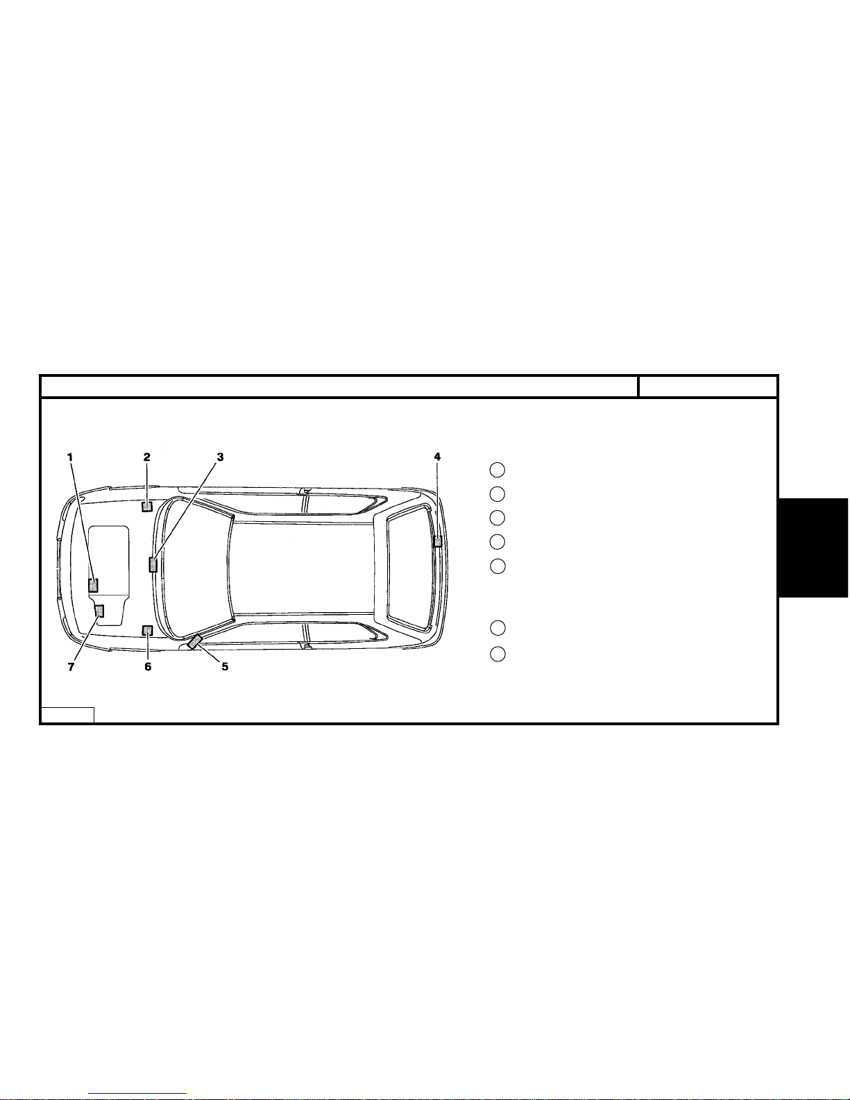
SAXO - All TypesIDENTIFICATION OF VEHICLES
E1AP07CD
1 Engine legislation type
2 RP organisation no.
3 Chassis stamp
4 Manufacturer’s name plate
5 01/02/99 # Label :
- Tyre pressures.
- RP organisation no.
- Paint code.
6 Paint code.
7 Gearbox ident. reference
GENERAL
Page 5
2
GENERAL
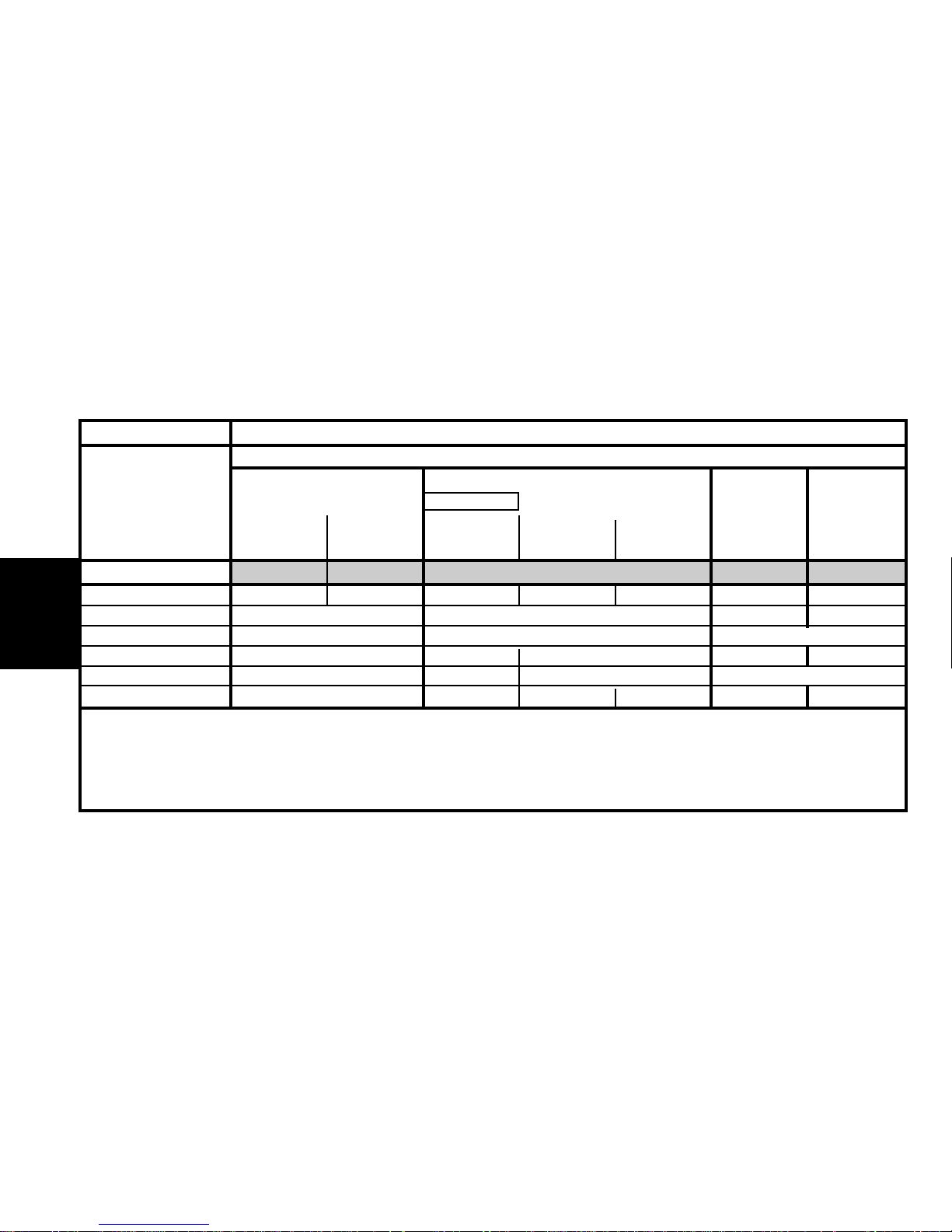
Emission standard IFL5 L4 L4 L4 L4
Type code SO HFX1 SO HFXB SO KFWL S6 KFWB SO KFWB S6 NFTB N6 NFXB
Engine type HFX KFW NFT NFX
Cubic capacity (cc) 1124 1360 1587
Fiscal rating (hp) 46558
Gearbox type MA/5 MB3 MA/5 MA/5
Gearbox ident. plate 20 CF 03 312 20 CF 12 20 CF 11 20 CN 05 20 CN 03
SAXO - All Types IDENTIFICATION OF VEHICLES
Saxo petrol 3-door.
1.1 i
1.4 i 1.6 i 1.6i 16V
X-SX
A-X-SX
Administration
Exclusive
SX
Exclusive VTS
SX
Exclusive
VTS VTS VTS
Auto.
Page 6
GENERAL
3
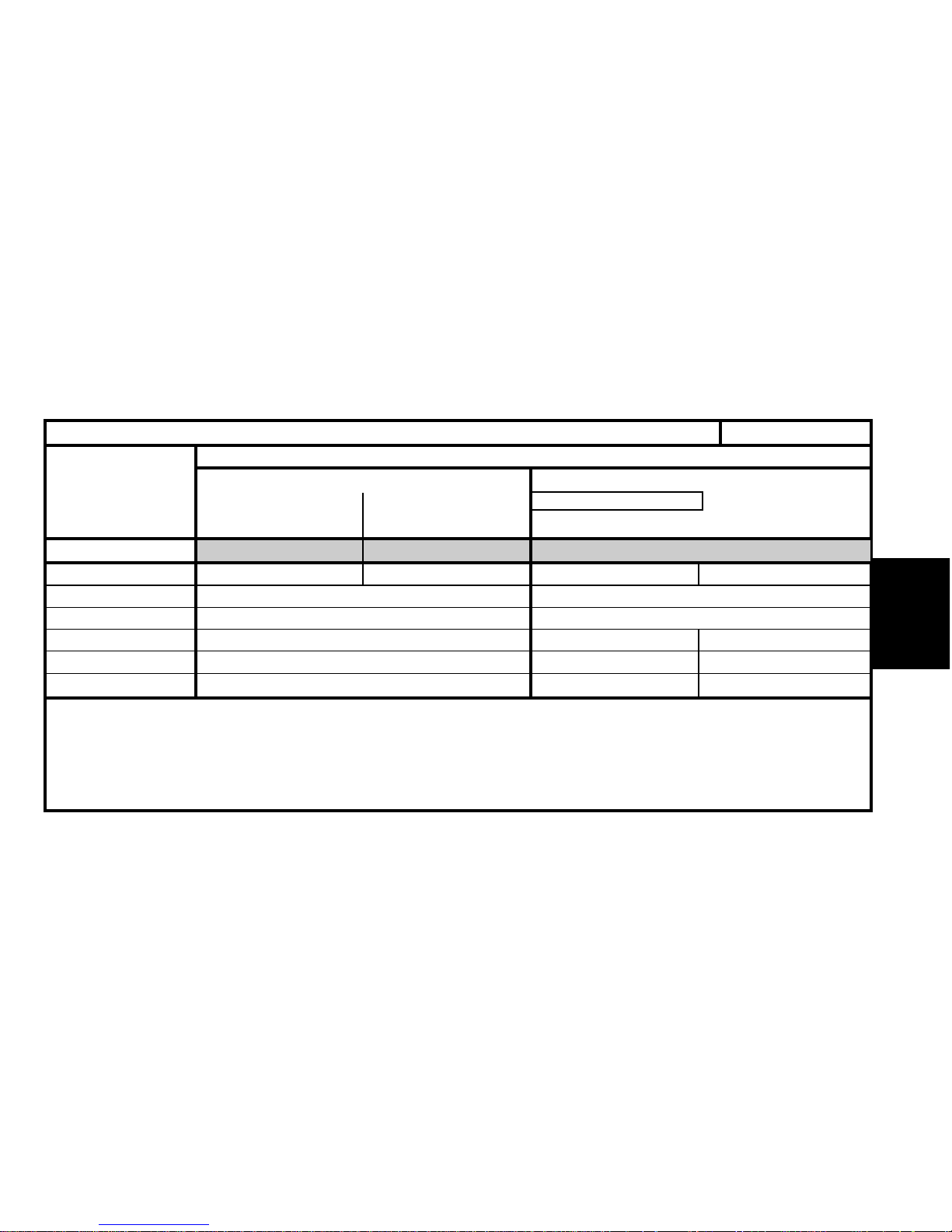
Emission standard IFL5 L4 L4
Type code S1 HFX1 S1 HFXB S1 KFWL S1 KFWB
Engine type HFX KFW
Cubic capacity (cc) 1124 1360
Fiscal rating (hp) 465
Gearbox type MA/5 MB3 MA/5
Gearbox ident. plate 20 CF 03 312 20 CF 12
SAXO - All TypesIDENTIFICATION OF VEHICLES
Saxo petrol 5-door.
1.1i 1.4i
A-Administration
Driving school -X-SX
Exclusive
SX-Exclusive
X-SX
Auto.
Page 7
4
GENERAL
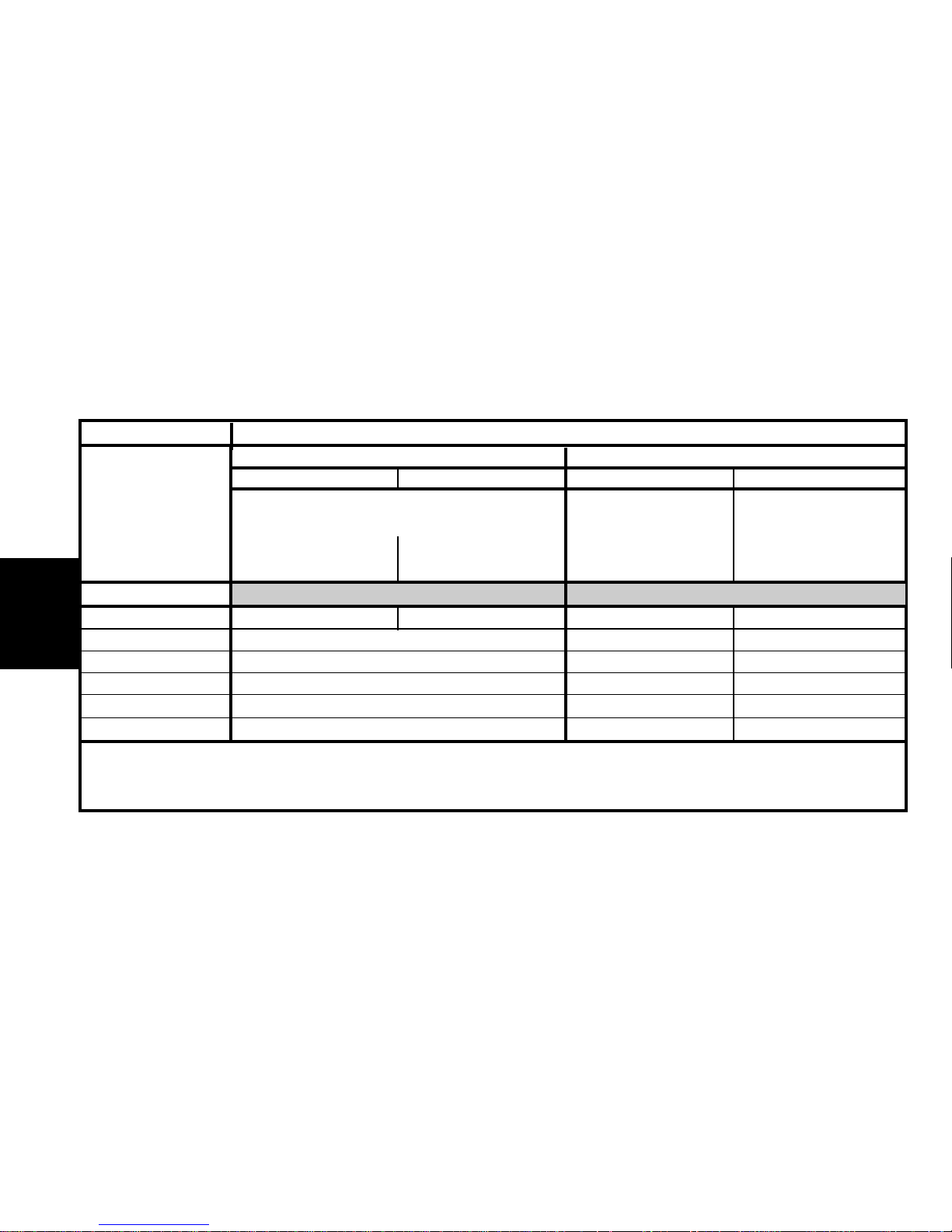
Emission standard L4 L4
Type code SO VJXB S1 VJXB S3 HFXB S3 VJXB
Engine type VJX HFX VJX
Cubic capacity (cc) 1527 1124 1527
Fiscal rating (hp) 466
Gearbox type MA/5 MA/5 MA/5
Gearbox ident. plate 20 CF 02 20 CF 03 20 CF 02
SAXO - All Types IDENTIFICATION OF VEHICLES
Diesel Entreprise
1.5 D
5-door.3-door. Diesel 3-door.Petrol 3-door.
1.5 D1.1i
A-Administration
Driving school
X-SX-Exclusive
A
Administration
Poste-X-SX
A
Administration
Poste-X-SX
A- Administration
X-SX-VTS -Exclusive
Page 8
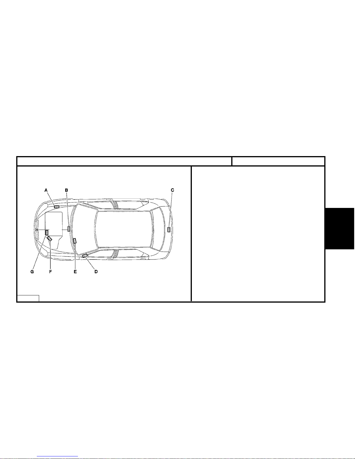
GENERAL
IDENTIFICATION OF VEHICLES
E1AP08WD
A - Manufacturer’s name plate (Estate).
B - Chassis stamp, cold stamp.
C - Manufacturer’s name plate (Saloon).
D - Label :
(label affixed to the front pillar on driver’s side)
- Tyre pressures.
- RP organisation no.
- Paint code.
E - Serial number. (visible through the windscreen)
F - Engine legislation type.
Factory serial no
G - Gearbox ident. reference.
Factory serial no.
XSARA - All Types # 09/2000
5
Page 9
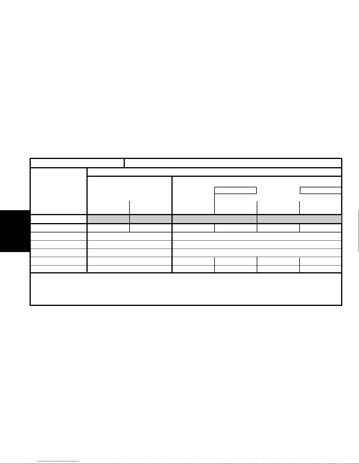
6
GENERAL
Emission standard L4 IFL5 L4 IFL5
Type code NO KFWB NO KFW1/IF NO NFUB NO NFUN NO NFU1/IF NO NFU3/IF
Engine type KFW NFU
Cubic capacity (cc) 1360 1581
Fiscal rating (hp) 57
Gearbox type MA/5 MA/5 AL4 MA/5 AL4
Gearbox ident. plate 20 CF 13 20 CN 28 20 TP 49 20 CN 28 20 TP 49
XSARA - All Types 09/2000 #
IDENTIFICATION OF VEHICLES
Saloon petrol 3-door.
1.4 i
1.6i 16V
X-VTR
X-SX-VTR
VTS
VTR-VTSSX-VTR VTR
Auto.
Auto.
X-SX
VTR
Page 10

7
GENERAL
Emission standard IFL5 L4 L4
Type code NO RFN1/IF NO RFNN/IF NO RFSB NO WJYB NO RHYB NO RHZB NO RHZN
Engine type RFN RFS WJY RHY RHZ
Cubic capacity (cc) 1998 1868 1997
Fiscal rating (hp) 8115 6
Gearbox type BE4/5 AL4 BE3/5 BE4/5 AL4
Gearbox ident. plate
20 DL 40 20 DL 41 20 DL 42 20 DM 10
20 TP 48
20 DM 03 (1)
20 TP 47 20 TE 47
20 DM 05 (1) 20 DM 07 (1) 20 DM 11 (1)
XSARA - All Types 09/2000 #
IDENTIFICATION OF VEHICLES
Saloon diesel 3-door.Saloon petrol 3-door.
20i.16V
1.9 D 2.0 HDi
VTS
X-SX
VTR
X-SX-VTR
VTS
SX-VTR
VTS SX
Auto. Auto.
(1) = Right hand drive : Hydraulic clutch control.
Page 11
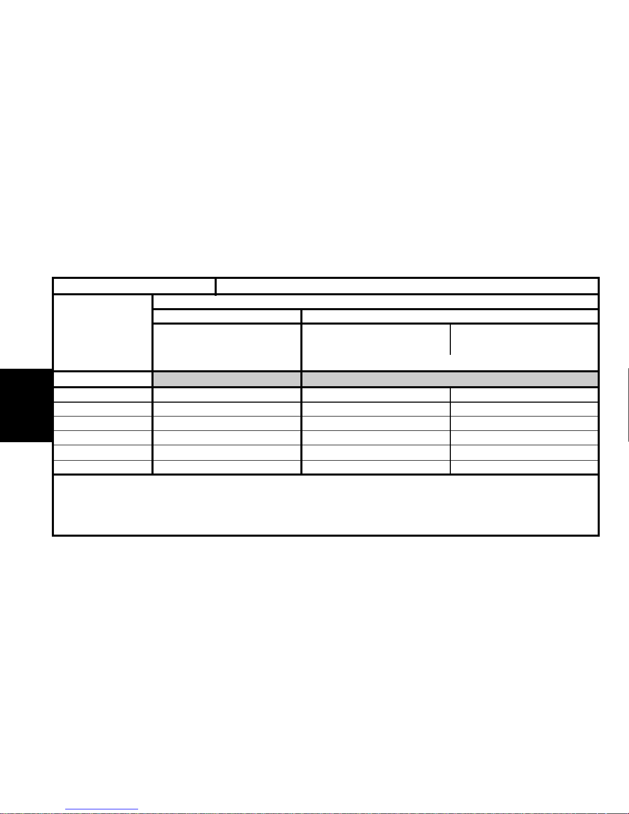
8
GENERAL
Emission standard L4 L4
Type code NO KFWB/T (1) NO WJYB/T (1) NO RHYB/T (1)
Engine type KFW WJY RHY
Cubic capacity (cc) 1360 1868 1997
Fiscal rating (hp) 87 6
Gearbox type MA/5 BE4/5
Gearbox ident. plate 20 CF 13 20 DL 41 20 DL 42
IDENTIFICATION OF VEHICLES
(1) /T = The vehicle cannot be converted back into a private vehicle.
Saloon 3-door versions
DieselPetrol
1.4i 1.9 D 2.0 HDi
X
X
XSARA - All Types # 09/2000
Page 12
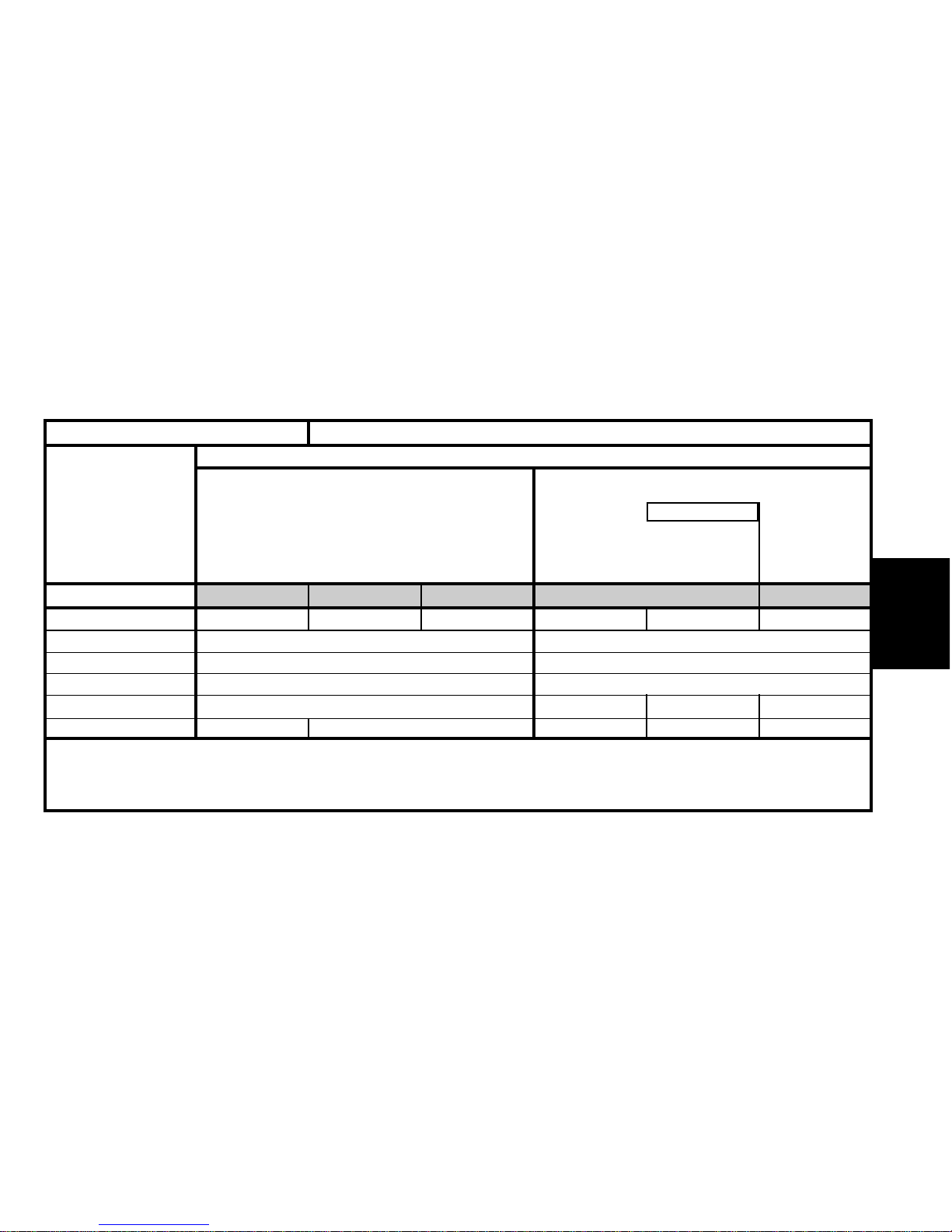
9
GENERAL
Emission standard K’ L4 IFL5 K’ L4
Type code N1 KFWG N1 KFWB N1 KFW1/IF N1 NFUG N1 NFUU N1NFUB
Engine type KFW NFU
Cubic capacity (cc) 1360 1587
Fiscal rating (hp) 57
Gearbox type MA/5 MA/5 AL4 MA/5
Gearbox ident. plate 20 CN 30 20 CF 13 20 CN 29 20 TP 49 20 CN 28
XSARA - All Types 09/2000 #
IDENTIFICATION OF VEHICLES
Saloon petrol 5-door
1.4i
1.6i 16V
X-SX
SX
X-SX
Exclusive
Auto.
Page 13
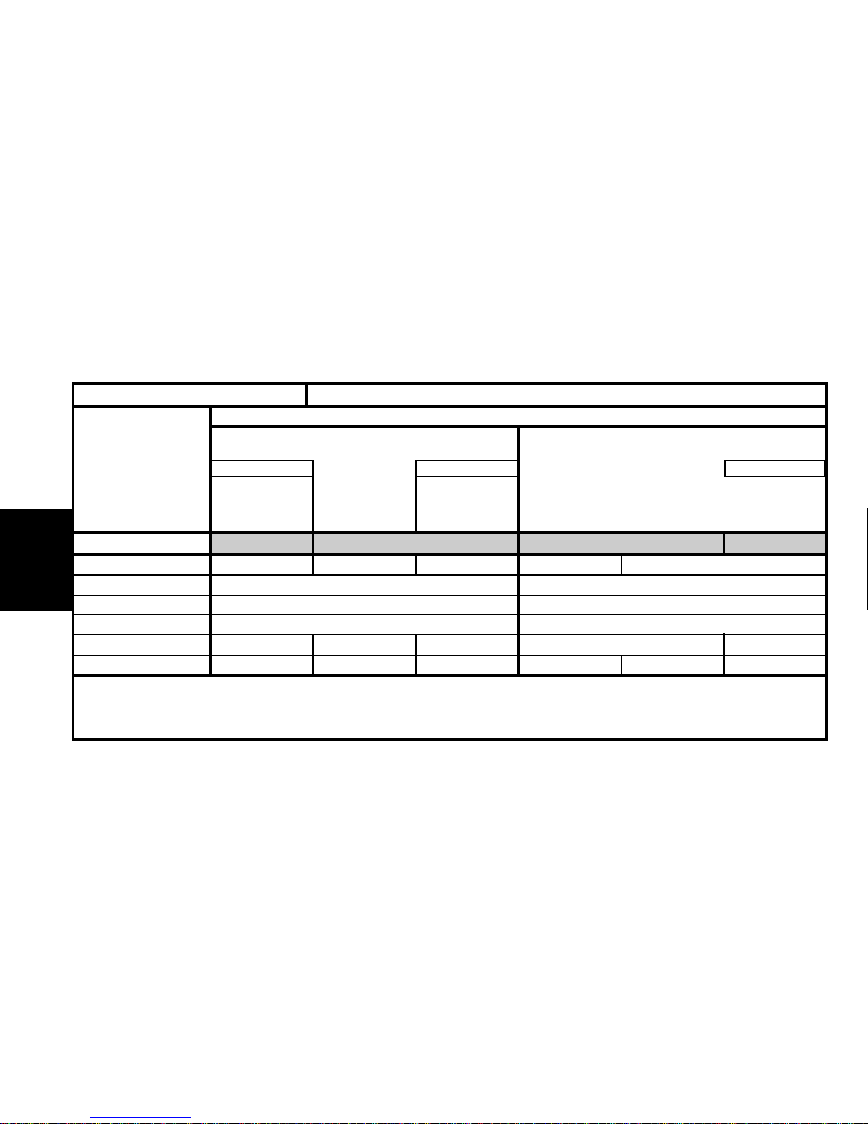
10
GENERAL
Emission standard L4 IFL5 IFL5 L4
Type code N1 NFUN N1 NFU1/IF N1 NFU3/IF N1 RFN1/IF N1 RFNN
Engine type NFU RFN
Cubic capacity (cc) 1587 1998
Fiscal rating (hp) 711
Gearbox type AL4 MA/5 AL4 BE4/5 AL4
Gearbox ident. plate 20 TP 49 20 CN 28 20 TP 49 20 DL 40 20 DM 03 (1) 20 TP 47
XSARA - All Types 09/2000 #
IDENTIFICATION OF VEHICLES
(1) = Right hand drive : Hydraulic clutch control.
Saloon petrol 5-door.
16i 16V
2.0i 16V
X-SX
Exclusive
SX
Exclusive
Exclusive
Auto.
Auto. Auto.
SX
Exclusive
Page 14
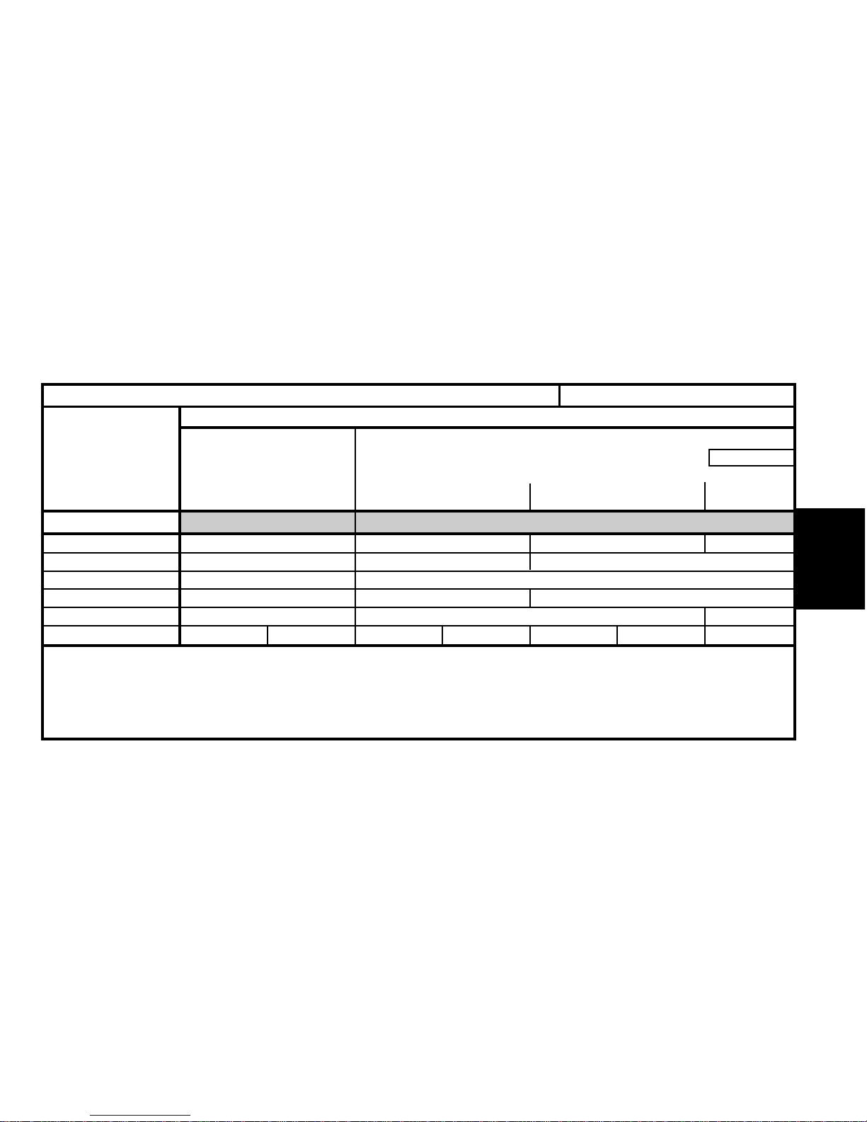
11
GENERAL
Emission standard L4 L4
Type code N1 WJYB N1 RHYB N1 RHZB N1 RHZN
Engine type WJY RHY RHZ
Cubic capacity (cc) 1868 1997
Fiscal rating (hp) 55 6
Gearbox type BE4/5 BE4/5 Al4
Gearbox ident. plate 20 DL 41 20 DM 05 (1) 20 DL 42 20 DM 07 (1) 20DM 10 20 DM 11 (1) 20 TP 48
XSARA - All Types 09/2000 #
IDENTIFICATION OF VEHICLES
Saloon diesel 5-door.
1.9 D
2.0 HDi
X-SX X-SX-Exclusive SX-Exclusive
SX
Exclusive
Auto.
(1) = Right hand drive : Hydraulic clutch control.
Page 15
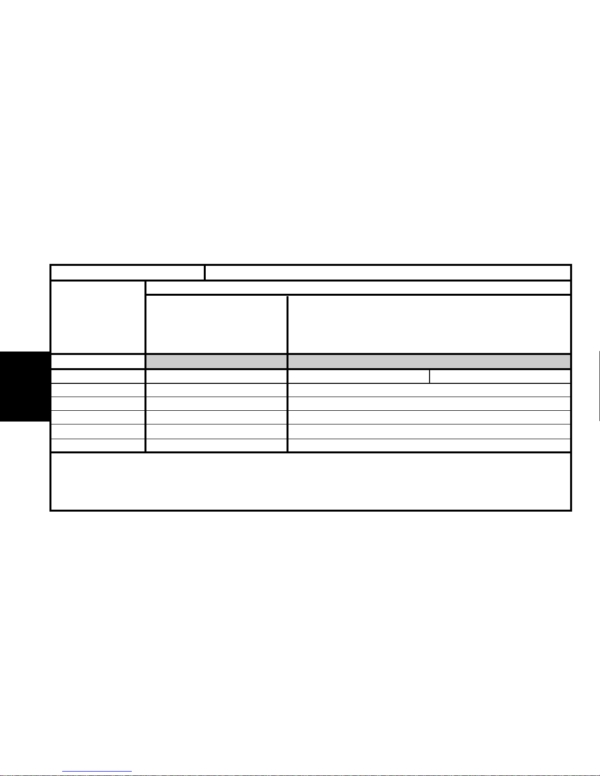
12
GENERAL
Emission standard L4 L4
Type code N1 WJYB/T (1) N RHYB N1 RHYB/T (1)
Engine type WJY RHY
Cubic capacity (cc) 1868 1997
Fiscal rating (hp) 75
Gearbox type BE4/5 BE4/5
Gearbox ident. plate 20 DL 41 20 DL 42
IDENTIFICATION OF VEHICLES
(1) /T = The vehicle cannot be converted back into a private vehicle.
Saloon diesel Entreprise 5-door.
2.0 HDi1.9 D
X
X
XSARA - All Types # 09/2000
Page 16
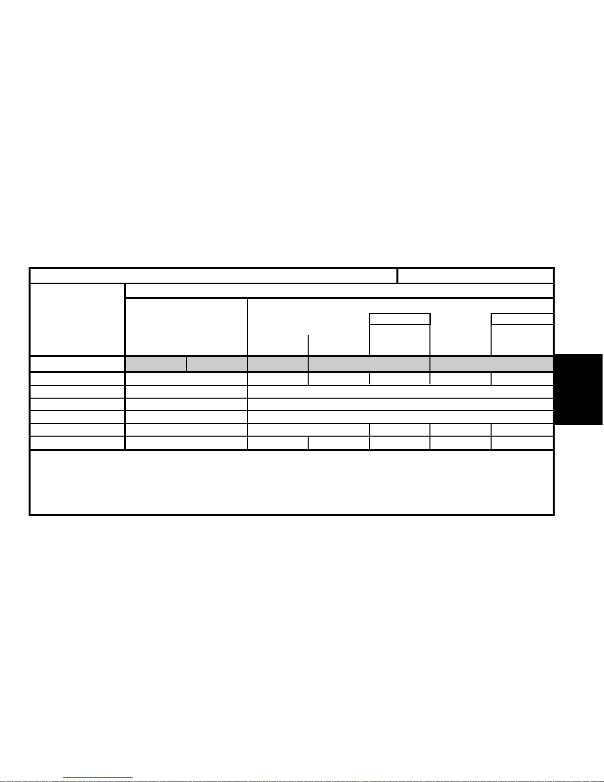
13
GENERAL
Emission standard L4 IFL5 K’ L4 IFL5
Type code N2 KFWB KFW1/IF N2 NFUG N2 NFUB N2 NFUN N2 NFU1/IF N2 NFU3/IF
Engine type KFW NFU
Cubic capacity (cc) 1360 1587
Fiscal rating (hp) 57
Gearbox type MA/5 MA/5 AL4 MA/5 AL4
Gearbox ident. plate 20 CN 21 20 CN 29 20 CN 28 20 TP 49 20 CN 28 20 TP 49
XSARA - All Types 09/2000 #
IDENTIFICATION OF VEHICLES
Estate petrol
1.4i
16. 16V
X-SX
X-SX
EclusiveSX
X-SX
Exclusive
SX
Exclusive
SX
Exclusive
Auto.Auto.
Page 17
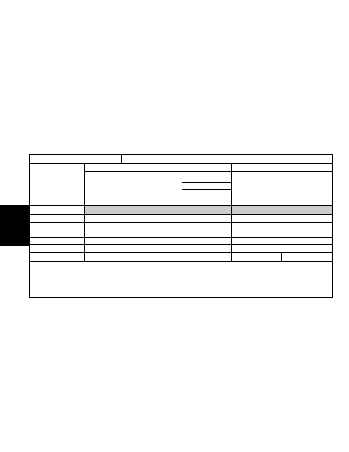
14
GENERAL
Emission standard IFL5 L4 L4
Type code N2 RFN1/IF N2 RFNN N2 WJYB
Engine type RFN WJY
Cubic capacity (cc) 1998 1868
Fiscal rating (hp) 11 5
Gearbox type BE4/5 AL4 BE4/5
Gearbox ident. plate 20 DL 40 20 DM 03 (1) 20 DL 41 20 DM 05 (1)
XSARA - All Types # 09/2000
IDENTIFICATION OF VEHICLES
Estate dieselEstate petrol
1.9 D2.0i 16V
Exclusive
X - SX
(1) = Right hand drive : Hydraulic clutch control.
Auto.
Page 18
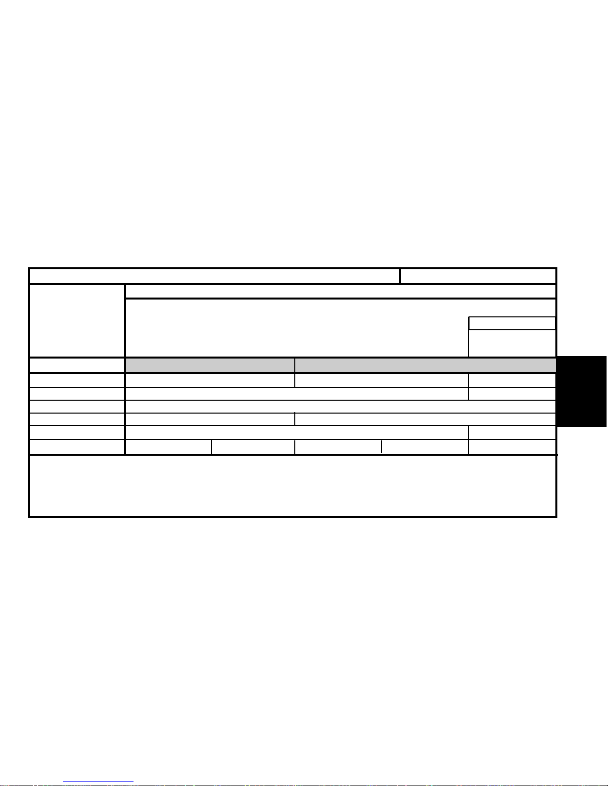
15
GENERAL
15
Emission standard L4 IFL5
Type code N2 RHYB N2 RHYB/IF N2 RHZN
Engine type
RHY RHZ
Cubic capacity (cc) 1997
Fiscal rating (hp) 56
Gearbox type BE4/5 AL4
Gearbox ident. plate 20 DL 42 20 DM 07 (1) 20 DM 10 20 DM 11 (1) 20 TP 48
IDENTIFICATION OF VEHICLES
Estate diesel
2.0 HDi
X-SX-Eclusive
SX
Exclusive
(1) = Right hand drive : Hydraulic clutch control.
Auto.
XSARA - All Types # 09/2000
Page 19
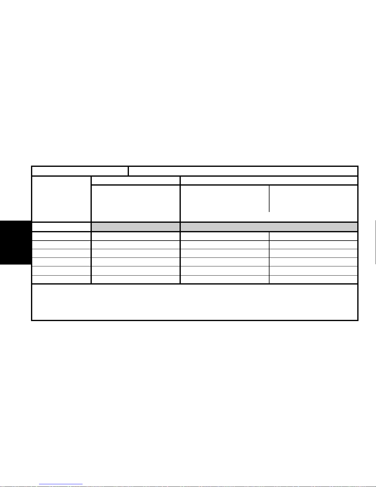
16
GENERAL
Emission standard L4 L4
Type code N2 KFWB/T (1) N2 WJYB/T (1) N2 RHYB/T (1)
Engine type KFW WJY RHY
Cubic capacity (cc) 1360 1868 1997
Fiscal rating (hp) 87 6
Gearbox type MA/5 BE4/5 BE4/5
Gearbox ident. plate 20 CN 21 20 DL 41 20 DL 42
IDENTIFICATION OF VEHICLES
(1) /T = The vehicle cannot be converted back into a private vehicle.
Estate diesel versionsEstate petrol versions
2.0 HDi1.9 D1.4i
X
X
XSARA - All Types # 09/2000
Page 20
17
GENERAL
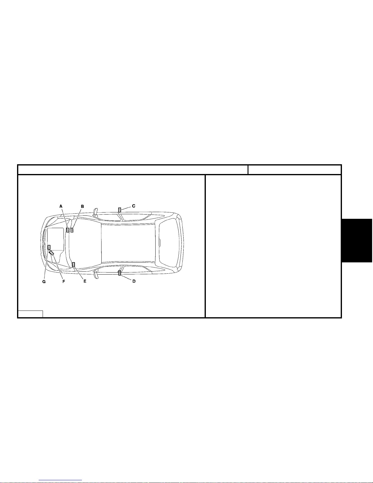
IDENTIFICATION OF VEHICLES
XSARA PICASSO - All Types
E1AP088D
A - Chassis stamp
(Cold stamp on bodywork)
B - Chassis no. reminder
(Label located at bottom of windscreen right hand side)t)
C - Manufacturer’s data plate.
(Located at bottom of RH central pillar)
D - Label :
Tyre pressures.
Tyre identification.
Spare wheel identification.
(Located on front LH door inner panel).
E - Label
Factory code.
A-S / RP N°
Paint code.
(Located on fuse box cover)
F - Gearbox identification ref.
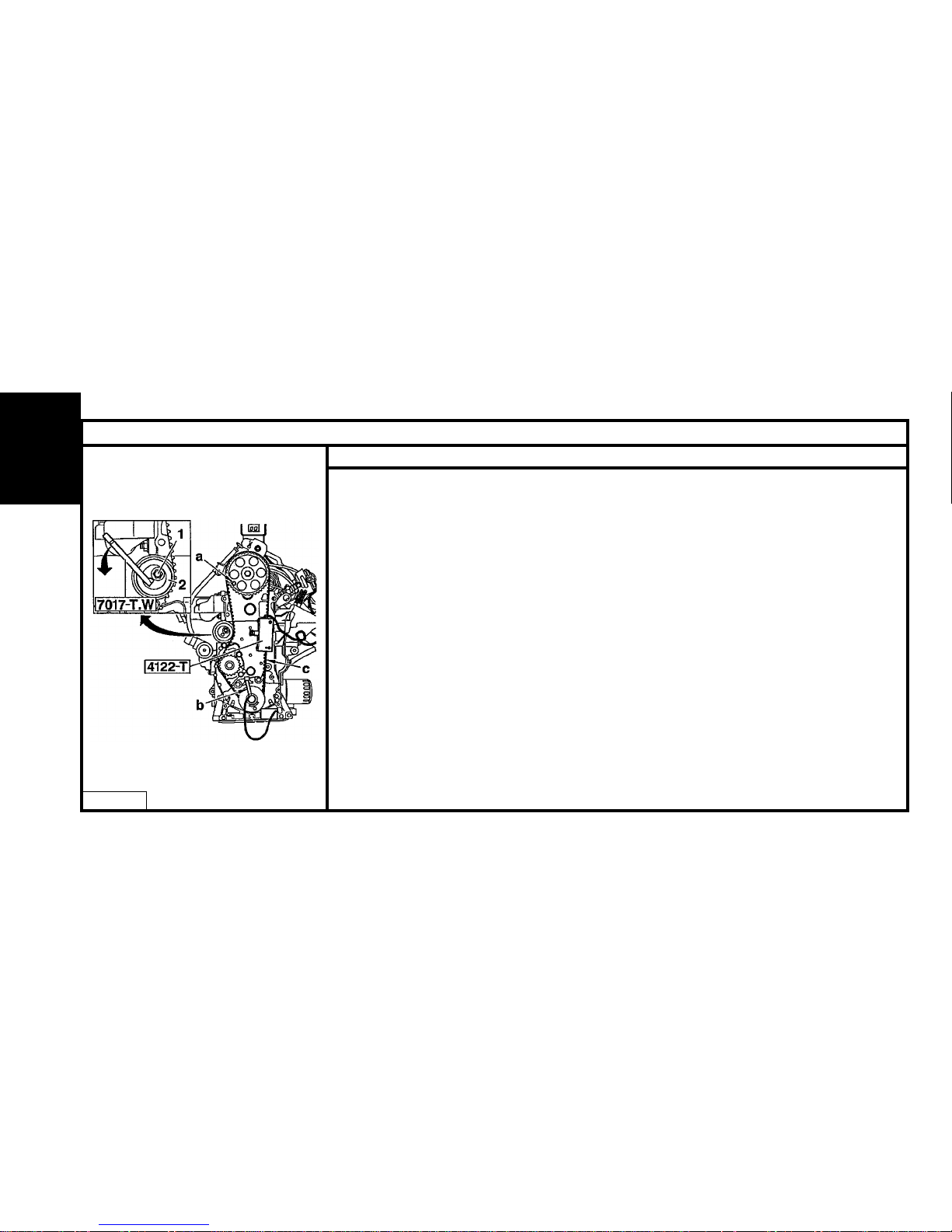
G - Engine legislation type.
Factory serial number.
Page 21
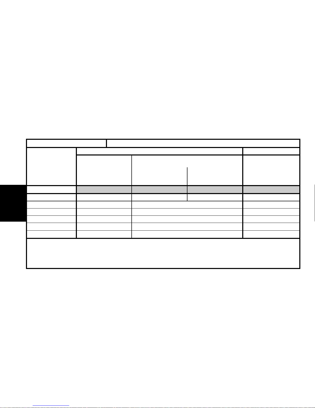
18
GENERAL
Emission standard L3 L4 IFL5 L4
Type code CH NFVB CH 6FZB CH 6FZ/IF CH RHY
Engine type NFV 6FZ RHY
Cubic capacity (cc) 1587 1749 1997
Fiscal rating (hp) 67 5
Gearbox type BE4/5/ J (*) BE4/5 V (*) BE4/5 L (*)
Gearbox ident. plate 20 DL 66 20 DL 68 20 DL 64
XSARA PICASSO - All Types IDENTIFICATION OF VEHICLES
Petrol Diesel
1.8i 16 V1.6i 2.0 HDi
(*) L.J V = Corresponds to the stepping of the gears.
Page 22
19
GENERAL
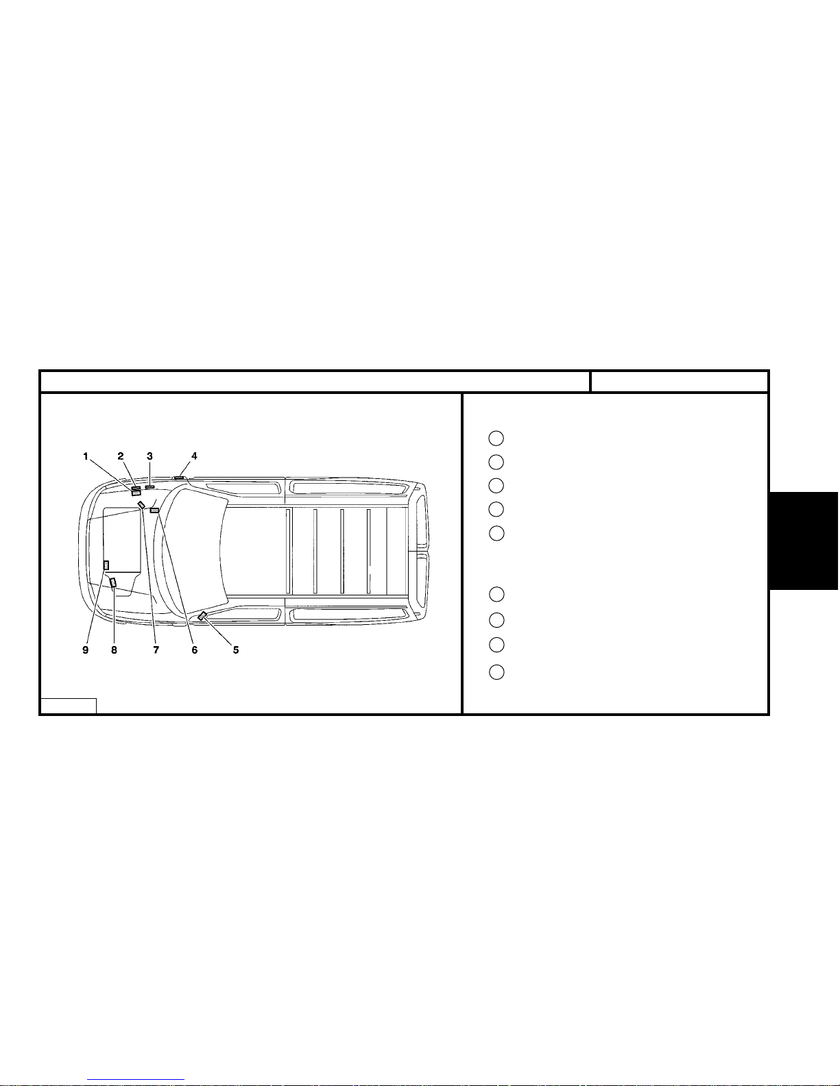
IDENTIFICATION OF VEHICLES
BERLINGO - All Types
E1AP07AD
1 Chassis stamp
2 Manufacturer’s name plate.
3 Supplementary plate
4 Weights label
5 01/02/99 # Label :
- Tyre pressures.
- RP organisation no.
- Paint code.
6 Paint code
7 RP organisation no.
8 Gearbox ident. reference
9 Engine legislation type
Page 23
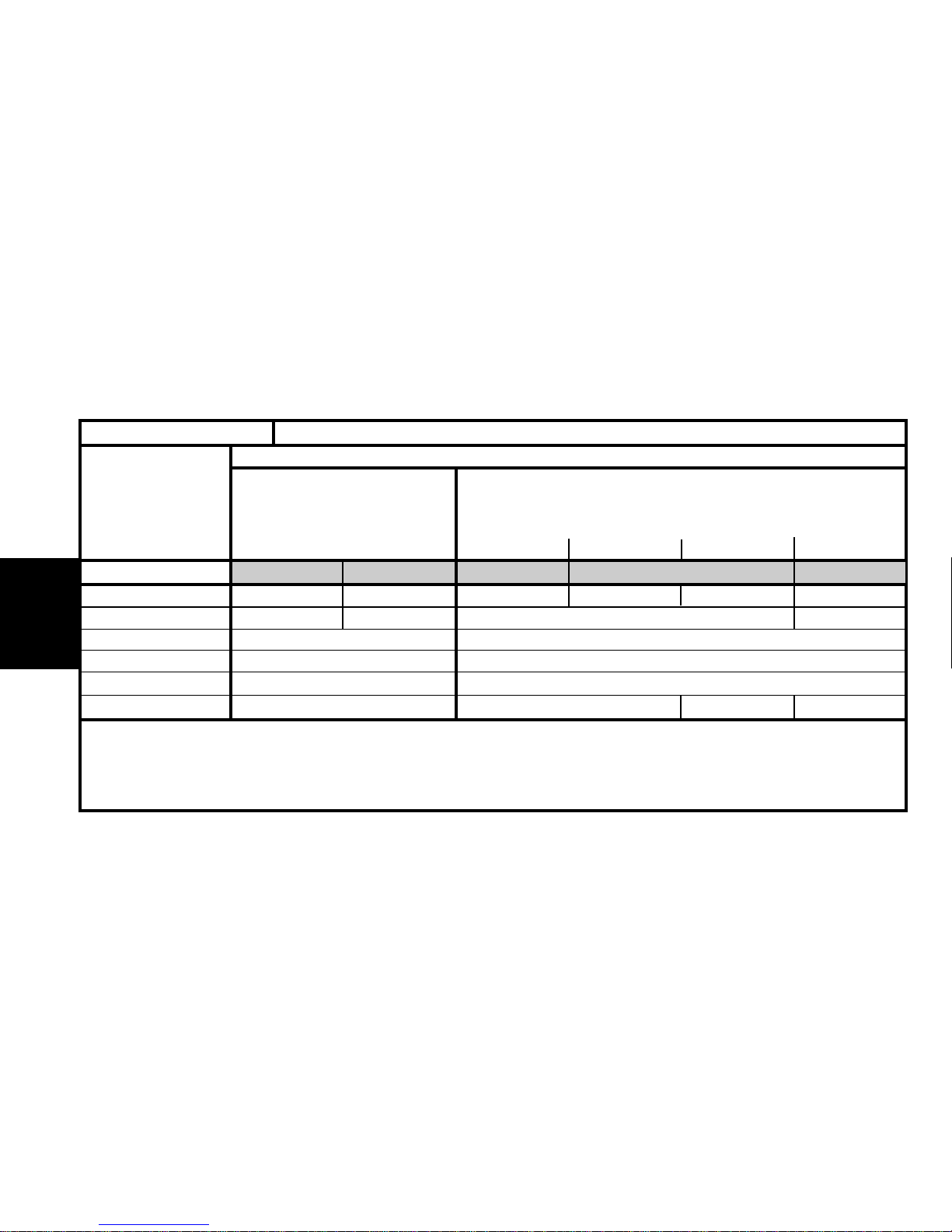
20
GENERAL
Emission standard L3/W3 L4/W4 K' L3/W3 L4/W4
Type code MF HDZF MF HFX MF KFXG MF KFXF MF KFXF/A MF KFWB
Engine type HDZ HFX KFX KFW
Cubic capacity (cc) 1124 1360
Fiscal rating (hp) 56
Gearbox type MA/5 MA/5
Gearbox ident. plate 20 CN 02 20 CN 12 20 CN 13 20 CN 12
IDENTIFICATION OF VEHICLES
Berlingo petrol 5-seater
1.1i 1.4i
X-SX
X-SXMultispace
XX
BERLINGO - All Types
Page 24
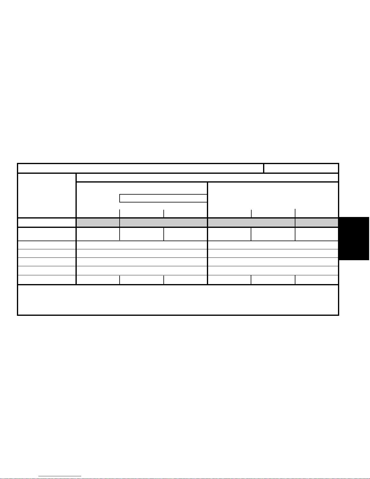
21
GENERAL
Emission standard L4/W4 L4 L4/W4 IFL5
Type code
MF KFWB/A
MF KFWB MF KFWB
MF NFUB MF NFUB/A MF NFU1/IF
/MOD GL (1) /AMOD GL (1)
Engine type KFW NFU
Cubic capacity (cc) 1360 1581
Fiscal rating (hp) 67
Gearbox type MA/5 BE4/5
Gearbox ident. plate 20 CN 13 20 CN 12 20 CN 13 20 TL 37 20 TL 38 20 TL 37
IDENTIFICATION OF VEHICLES
Berlingo petrol 5-seater
1.4i 1.6i 16V
SX
SXMultispace
MultispaceXMultispace
BERLINGO - All Types
Dual fuel
(1) /MOD GL = MOD, Modified ; GL = LPG = (Liquified Petroleum Gas), with ring-shaped tank.
Page 25
22
GENERAL
Emission standard IFL5 L3/W3 L3/W3 L4/W4
Type code MF NFU1/A IF MF LFXF MF LFXF/A MF WJZF MF WJZF/A MF WJYB
Engine type NFU LFX WJZ WJY
Cubic capacity (cc) 1581 1761 1868
Fiscal rating (hp) 77 5
Gearbox type BE4/5 BE3/5 BE3/5
Gearbox ident. plate 20 TL 38 20 TE 25 20 TE 26 20 TE 22 20 TE 24 20 TE 49
IDENTIFICATION OF VEHICLES
Berlingo diesel 5-seaterBerlingo petrol 5-seater
16i 16V 1.8i
(1)
1.9 D
X-SX
X-SXMultispace
MultispaceMultispace SX
BERLINGO - All Types
(1) = Marketed in MERCOSUR countries.
Page 26
23
GENERAL
Emission standard L4/W4 L3/W3 L4/W4
Type code
MF WJYB/A
MF WJYB
MF RHYF MF RHYF/A MF RHYB MF RHYB/A
/PMF (1)
Engine type WJY RHY
Cubic capacity (cc) 1868 1997
Fiscal rating (hp) 56
Gearbox type BE3/5 BE3/5
Gearbox ident. plate 20 TE 24 20 TE 28 20 TE 29 20 TE 28 20 TE 29
IDENTIFICATION OF VEHICLES
Berlingo diesel 5-seater
1.9 D 2.0 HDi
Multispace
MultispaceX-SX
X-SX
SX
MultispaceMultispace
BERLINGO - All Types
(1) /PMF = Multifunction roof
Page 27
24
GENERAL
CAPACITIES (in litres)ALL TYPES
Draining method.
The oil capacities are defined according to the following methods.
1/ Vehicle on level surface (in high position, if equipped with hydropneumatic suspension).
2/ Engine warm (oil temperature 80°C).
3/ Draining of the oil sump + removal of the cartridge (duration of draining + dripping = 15 min).
4/ Refit plug + cartridge.
5/ Engine filling.
6/ Engine starting (allowing the cartridge to be filled).
7/ Engine stopped (stationary for 5 min).
ESSENTIAL : Systematically check the oil level using the oil dipstick.
Page 28
25
GENERAL
Ecological oil filter
capacity 0.15 litre.
Engine type
Engine with filter change
Between Min. and Max.
5-speed gearbox
Automatic gearbox
after drainage
Hydraulic or brake circuit
Cooling system
Fuel tank capacity
HFX KFW NFX NFT VJX
3 3.5 4.5
1.5 1.5 2
22
4.5
2
With ABS = 0.45 - Without ABS = 0.36
6.1
45
SAXO - All Types CAPACITIES (in litres)
DieselPetrol
SAXO
1.1I 1.4I 1.6I 16V 1.5D1.6I
ESSENTIAL : systematically check the oil level using the oil dipstick.
Auto.
Page 29

26
GENERAL
Engine type
Engine with filter change
Between Min. and Max.
5-speed gearbox
Automatic gearbox
after drainage
Hydraulic or brake circuit
Cooling system
Fuel tank capacity
KFW NFU RFN RFS WJZ RHY RHZ
3 3.25 4.25 4.75 4.5-4.25 (1)
1.4 1.5 1.7 1 1.6 1.4
2 1.9 1.9 1.8
6 6 8.3
3 3 5.3
With ABS = 0.50 - Without ABS = 0.55
7 8.5
6.5 (1)
9
11 (1)
54
XSARA - All Types
CAPACITIES (in litres)
Ecological oil filter
capacity 0.15 litre.
Petrol Diesel
XSARA
(1) = With aircon - ESSENTIAL : systematically check the oil level using the oil dipstick.
1.4I 1.6I 16V 2.0I 16V 1.9D 2.0 HDI
Auto.
Auto. Auto.
Page 30
27
GENERAL
Ecological oil filter
capacity 0.15 litre.
Engine type
Engine with filter change
Between Min. and Max.
5-speed gearbox
Automatic gearbox
after drainage
Hydraulic or brake circuit
Cooling system
Fuel tank capacity
NFV 6FZ RHY
3 4.25 4.5
1.5 1.7 1.4
1.8
0.58 litres
5.8 (1) and (2) 6.5 (1) and (2) 11 (1) and (2)
55 60
XSARA PICASSO - All TypesCAPACITIES (in litres)
DieselPetrol
XSARA PICASSO
1.6I 1.8I 16 V 2.0 HDI
(1) = With aircon
(2) = Without aircon
ESSENTIAL : systematically check the oil level using the oil dipstick.
Page 31
28
GENERAL
Engine type
Engine with filter change
Between Min. and Max.
5-speed gearbox
Hydraulic or brake circuit
Cooling system
Fuel tank capacity
HDZ HFX KFX KFW LFX HFX KFX KFW NFU WJZ WJY RHY
3.5
4.75
3 3.25
4.75 4.5
4.5 (1) 4.5 (1) 4.25 (1)
1.5 1.3 1.5 1.5 1.5
2 1.8 2 1.8
With ABS = 0.62 - Without ABS = 0.525
With ABS = 0.62
Without ABS = 0.525
6.5 6.5-7 (1) 8 6.5 6.5-7 (1) 10.5
55 60
CAPACITIES (in litres)BERLINGO - All Types
BERLINGO
DieselPetrol
1.1i 1.4i 1.8i 1.1i 1.4i
1.6i
16V
1.9 D
2.0 HDi
(1) With aircon
ESSENTIAL : systematically check the oil level using the oil dipstick.
Ecological oil filter
capacity 0.15 litre.
Page 32
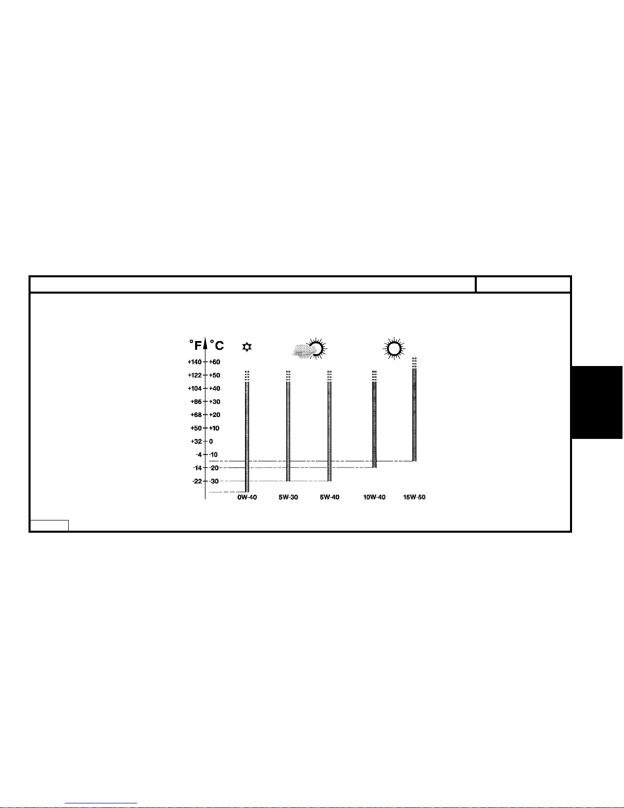
29
GENERAL
ALL TYPES
LUBRICANTS - TOTAL recommended oils
S.A.E. Norm - Table for selection of engine oil grade
E4AP006D
Page 33
30
GENERAL
ALL TYPES
LUBRICANTS - TOTAL recommended oils
Factory evolutions in 2001 model year
CITROËN engines are lubricated at the factory withTOTAL oil of grade
S.A.E.5W-30.
TOTAL oil of grade S.A.E.5W-30 allows improved fuel economies
(approx 2.5%).
Features of CITROËN C5 :
2.0 and 2.2 HDi engines have a particle filter.
The maintenance interval for normal operation
is 30.000 km (20.000 miles) for petrol engines.
WARNING : HDi engines are high technology engines which
imperatively require use of quality SYNTHETIC OILS : TOTAL
ACTIVA or TOTAL QUARTZ 5W40.
To maintain engine performances, all countries in Europe
should observe this requirement.
NOTE : Only PORTUGAL and GREECE may use 10W40 semi-synthetic
oil.
ESSENTIAL : For all vehicles with a 30.000 km (20.000 miles)
maintenance interval, use exclusively TOTAL ACTIVA/QUARTZ
7000 or 9000 or any other oils offering identical specifications to
these.
These oils offer specifications that are superior to those defined
by norms ACEA A3/98 or API SJ.
Failing this, it is essential to adhere to the maintenance programmes covering severe operating conditions.
5W30 cannot be used in the following engines:
XU10J4RS : XSARA VTS 2.0i 16V (3 doors).
SOFIM : RELAY 2.8 D and 2.8 TD.
1580 SPI : DISPATCH 1.6i.
2.0 and 2.2 HDi engines equipped with particle filter.
WARNING : CITROËN engines prior to model year 2000 do not
have to be lubricated with oils adhering to the norms ACEA A198/B1-98 and API SJ/CF EC.
Page 34
31
GENERAL
ALL TYPES
Selection of engine oil grades recommended for climatic conditions in countries of distribution
ACEA Norms
The first letter corresponds to the type of engine concerned :
A : petrol and dual fuel petrol / LPG engines.
B : diesel engines.
The figure following the first letter corresponds to the type of oil.
1 : highly fluid oils, for reducing friction and lowering fuel
consumption.
3 : high performance oils.
The number after that (96 or 98) corresponds to the year of creation of
the norm.
NOTE : From 01/03/2000, all engine oils must comply with ACEA-98
norms.
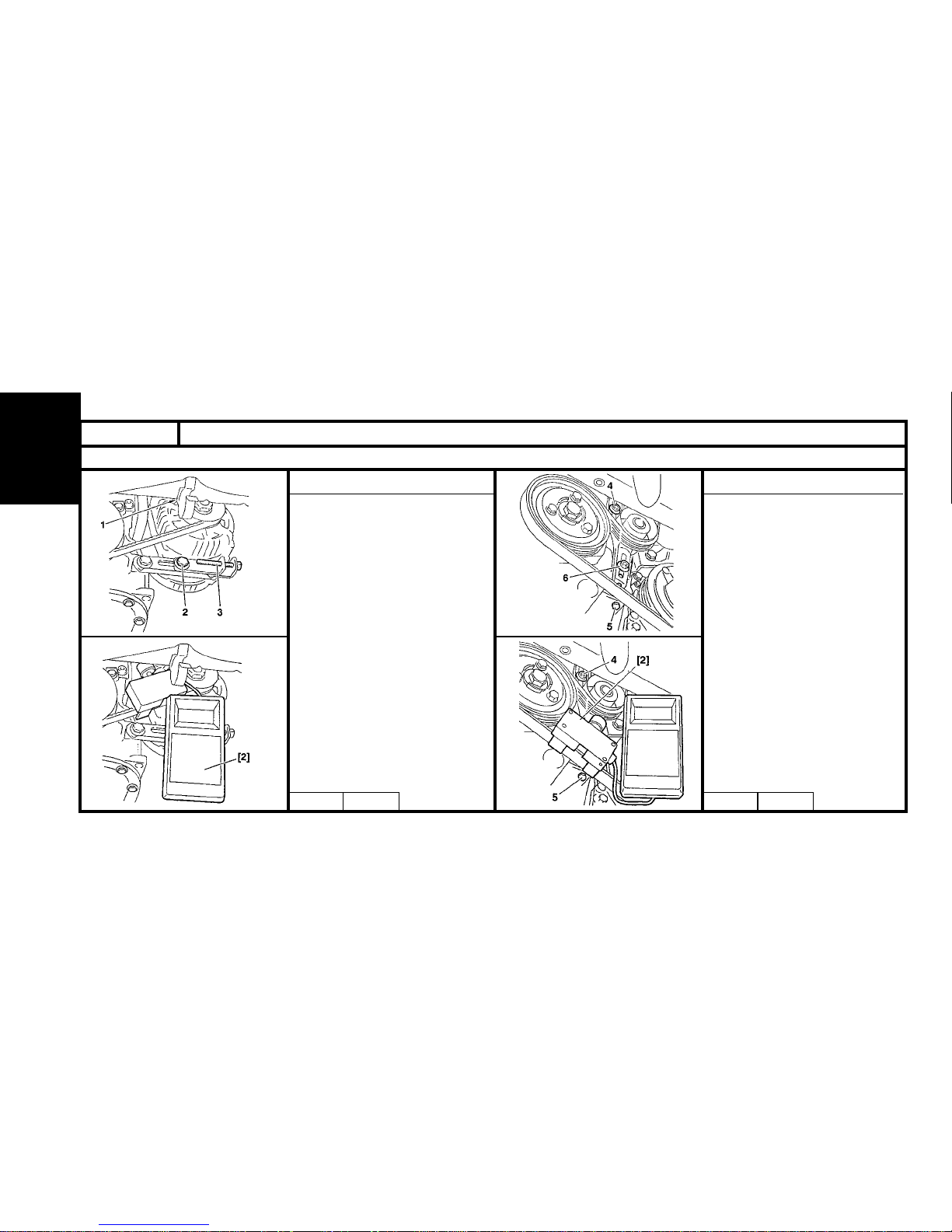
Example :
ACEA A1-98 / B1-98 : Blended oils for all engines, permitting fuel
economy (complying with ACEA 98 norms).
API Norms
The first letter corresponds to the type of fuel used by the engine :
S : petrol and dual fuel petrol / LPG engines.
C : diesel engines.
The second letter corresponds to the degree of evolution, in ascending order.
Example : The norm SJ is more severe than the norm SH and corresponds to a higher level of performance.
The adding of the letters EC indicates that the engine oil concerned is an
oil which permits fuel economy.
EC : Energy Conserving. reduction in fuel consumption.
Examples :
API SJ / CF : Blended oils for all engines.
engines API CF / EC : Oils specifically for diesel engines, permitting fuel
economy.
API SJ / CF / EC : Blended oils for all engines, permetting fuel economy.
LUBRICANTS - TOTAL recommended oils
Page 35
LUBRICANTS - TOTAL recommended oilsALL TYPES
32
GENERAL
Engine oil norms.
Norms in force.
These engine oils have been classified by the following recognised organisations:
S.A.E. : Society of Automotive Engineers.
API : American Petroleum Institute.
ACEA : Association des Constructeurs Européens d’Automobiles.
Recommendations.
Denominations of TOTAL oils, according to country of marketing:
TOTAL ACTIVA (France only).
TOTAL QUARTZ (Outside France).
Summary
Engine oil norms to be respected in 2001 model year.
(*) = It is essential not to use engine oils respecting these norms for the following engine-types.
XU10J4RS, 1580 SPI, SOFIM 2.8 D and SOFIM 2.8 TD.
ESSENTIAL : To preserve engine performances, all engines fitted in CITROEN vehicles must be lubricated with
high quality oils (synthetic or semi-synthetic)
Model year
AM 2001
Petrol and dual fuel petrol /
LPG engines
A3-98 or A1-98 (*) SJ or SJ / EC (*)
CF or CF / EC (*)B3-98 or B1-98 (*)Diesel engines
Types of engine ACEA norms API norms
Page 36
33
GENERAL
LUBRICANTS - TOTAL recommended oils
ALL TYPES
S.A.E. grades SPI norms ACEA norms
Blended oils for all engines (petrol, dual-fuel petrol / LPG and diesel)
TOTAL ACTIVA 9000
TOTAL QUARTZ 9000
5W-40 SJ / CF A3-98 / B3-98
TOTAL ACTIVA 9000 (*)
TOTAL QUARTZ 9000 (*)
5W-30 SJ / CF EC A1-98 / B1-98
TOTAL ACTIVRAC 10W-40 SJ / CF A3-98 / B3-98
(*) = Blended oils for all engines, permitting fuel economy.
Oils specifically for petrol and dual-fuel petrol / LPG engines
TOTAL ACTIVA 7000
TOTAL QUARTZ 7000
10W-40
TOTAL QUARTZ 9000 0W-40 SJ A3-98
TOTAL ACTIVA 7000
TOTAL QUARTZ 7000
15W-50
Oils specifically for diesel engines
TOTAL ACTIVA DIESEL 7000
TOTAL QUARTZ DIESEL 7000
10W-40
TOTAL ACTIVA DIESEL 7000 15W-50
CF B3-98
TOTAL ACTIVA DIESEL 9000 5W-40
Page 37
34
GENERAL
FRANCE
Metropolitan FRANCE
Metropolitan FRANCE
New Caledonia
Guadeloupe
Saint-Martin
La Réunion
9000 5W-40 7000 15W-50 7000 15W-50
Martinique
Guyane
Tahiti
Ile maurice
Mayotte
LUBRICANTS - TOTAL recommended oils
ALL TYPES
Blended oils for all engines, supplied in bulk
TOTAL ACTIVRAC S.A.E : 10W-40 Norms
TOTAL ACTIVA
Blended oils for all engines
9000 5W-40
9000 5W-30 (*)
7000 10 W-40
7000 10 W-40
9000 5W-40
Oils specifically for petrol and
dual-fuel petrol / LPG engines
Oils specifically for diesel
engines
TOTAL ACTIVA DIESEL
(*) = Blended oils for all engines, permitting fuel economy
Page 38
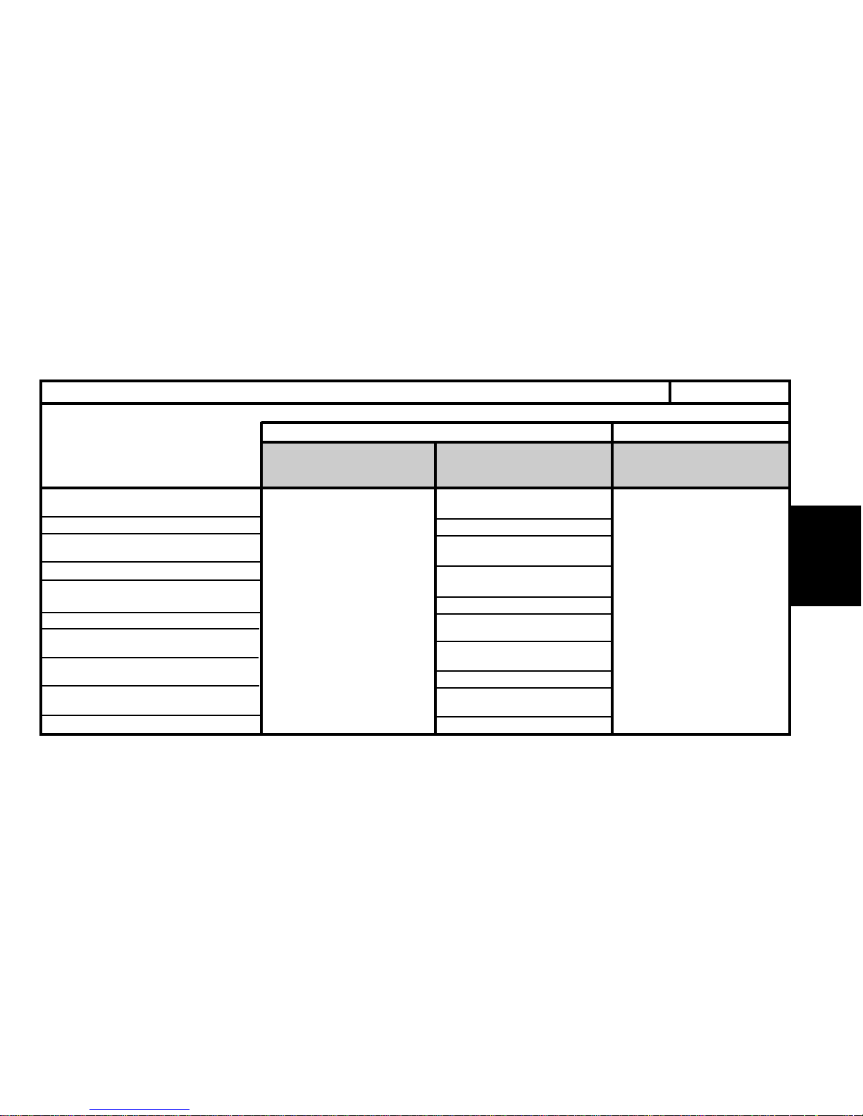
35
GENERAL
EUROPE
Germany
Austria
Belgium
Bulgaria
Cyprus
Croatia
Denmark
Spain
Finland
Great Britain
LUBRICANTS - TOTAL recommended oils
ALL TYPES
TOTAL QUARTZ TOTAL QUARTZ DIESEL
Blended oils for all engines
Oils specifically for petrol and
dual-fuel petrol / LPG engines
Oils specifically
for diesel engines
9000 5W-40
9000 5W-30 (*)
(*) = Blended oils for all engines,
permitting fuel economy.
7000 10W-40
7000 10W-40
9000 0W-40
7000 10W-40
7000 10W-40
9000 0W-40
7000 10W-40
7000 15W50
7000 10W-40
7000 10W-40
9000 0W-40
7000 10W-40
7000 15W-50
7000 10W-40
7000 10W-40
9000 0W-40
7000 10W-40
Page 39
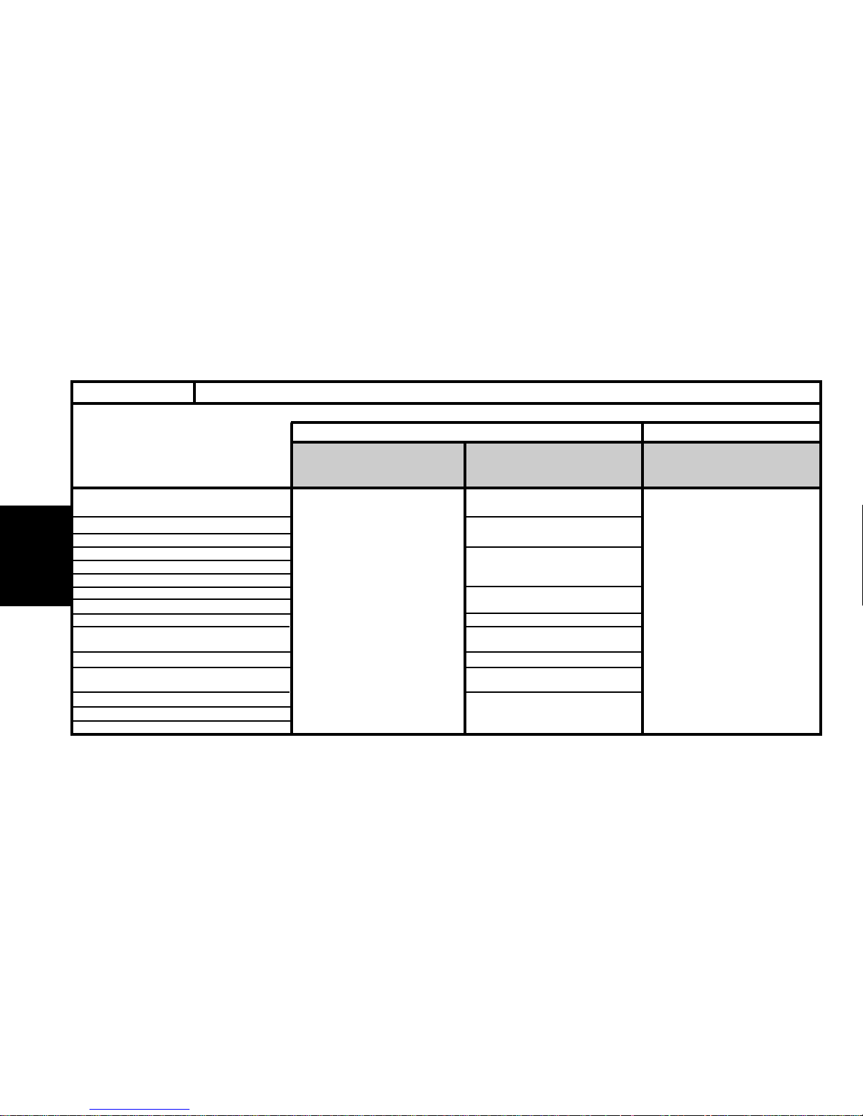
36
GENERAL
EUROPE (continued)
7000 10W-40
7000 15W-50
7000 10W-40
9000 0W-40
7000 10W-40
7000 10W-40
9000 0W-40
7000 10W-40
7000 10W-40
7000 15W-50
7000 10W-40
7000 10W-40
9000 0W-40
7000 10W-40
Greece
Holland
Hungary
Italy
Ireland
Iceland
Latvia
Lithuania
Macedonia
Malta
Moldova
Norway
Poland
Portugal
Slovak Republic
LUBRICANTS - TOTAL recommended oilsALL TYPES
TOTAL QUARTZ
TOTAL QUARTZ DIESEL
Blended oils for all engines
Oils specifically for petrol and
dual-fuel petrol / LPG engines
Oils specifically for diesel
engines
9000 5W-40
9000 5W-30 (*)
7000 10W-40
(*) = Blended oils for all engines,
permitting fuel economy.
Page 40
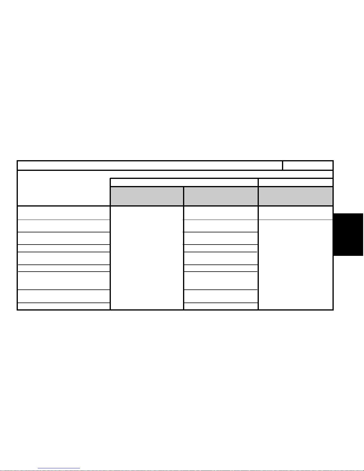
37
GENERAL
EUROPE (continued)
7000 10W-40
9000 0W-40
7000 10W-40
7000 15W-50
7000 10W-40
9000 0W-40
7000 10W-40
7000 10W-40
9000 0W-40
7000 10W-40
7000 10W-40
7000 15W-50
9000 0W-40
7000 10W-40
9000 0W-40
7000 10W-40
Czech Republic
Romania
Russia
Slovenia
Sweden
Switzerland
Turkey
Ukraine
Yugoslavia
LUBRICANTS - TOTAL recommended oils ALL TYPES
TOTAL QUARTZ TOTAL QUARTZ DIESEL
Blended oils for all engines
Oils specifically for petrol and
dual-fuel petrol / LPG engines
Oils specifically for diesel
engines
9000 5W-40
9000 5W-30 (*)
7000 10W-40
(*) = Blended oils for all engines, permit-
ting fuel economy
Page 41
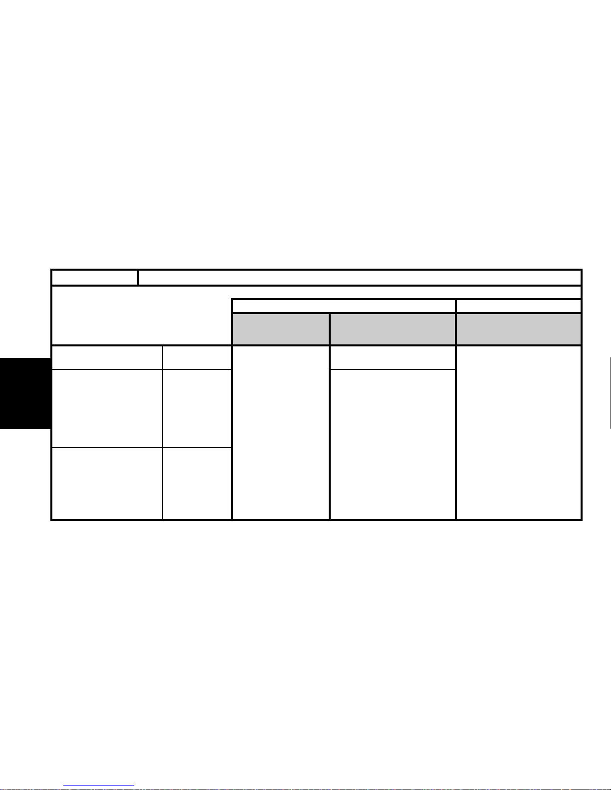
38
GENERAL
Australia
Nouvelle-Zélande
Ivory Coast
Egypt
Gabon
Madagascar
Morocco
Senegal
Tunisia
Argentina
Brazil, Chile
Cuba
Mexico
Paraguay
Uruguay
LUBRICANTS - TOTAL recommended oilsALL TYPES
TOTAL QUARTZ TOTAL QUARTZ DIESEL
Blended oils for all
engines
Oils specifically for petrol and
dual-fuel petrol / LPG engines
Oils specifically for diesel
engines
OCEANIA
AFRICA
9000 5W-40
7000 5W-40
7000 10W-40
7000 10W-40
CENTRAL
AND SOUTH
AMERICA
Page 42
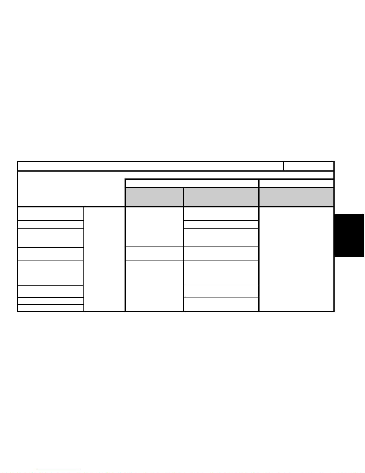
39
GENERAL
LUBRICANTS - TOTAL recommended oils ALL TYPES
China
South Korea
Hong Kong
India
Indonesia
Japan
Malaysia
Pakistan
Philippines
Singapore
Taïwan
Thailand
Vietnam
7000 10W-40
7000 15W-50
7000 10W-40
7000 15W-50
7000 10W-40
7000 15W-50
7000 15W-50
7000 10W-40
7000 15W-50
7000 15W-50
TOTAL QUARTZ TOTAL QUARTZ DIESEL
Blended oils for all
engines
Oils specifically for petrol and
dual-fuel petrol / LPG engines
Oils specifically for diesel
engines
SOUTH EAST
ASIA
9000 5W-40
9000 5W-40
9000 5W-30
7000 10W-40
9000 5W-40
(*) = Blended oils for all engines, permitting fuel economy
Page 43
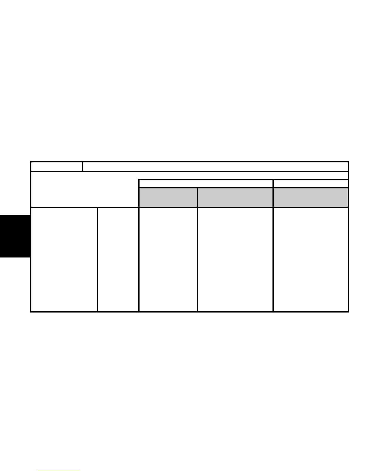
40
GENERAL
MIDDLE
9000 5W-40 7000 15W-50 7000 10W-50
EAST
LUBRICANTS - TOTAL recommended oilsALL TYPES
TOTAL QUARTZ TOTAL QUARTZ DIESEL
Blended oils for all
engines
Oils specifically for petrol and
dual-fuel petrol / LPG engines
Oils specifically for diesel
engines
Saudi Arabia
Bahrain
Dubai
United Arab Emirates
Iran
Israel
Jordan
Kuwait
Lebanon
Oman
Qatar
Yemen
Page 44
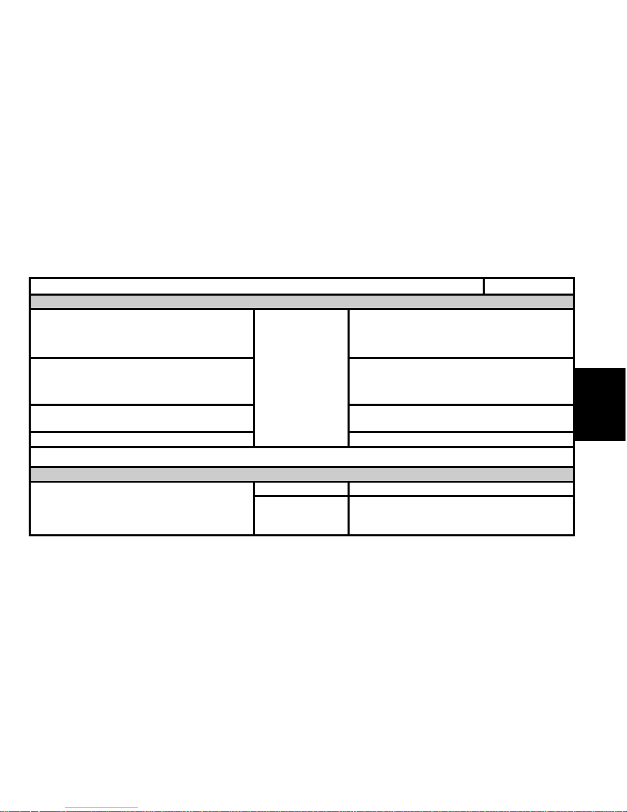
41
GENERAL
TOTAL TRANSMISSION BV
Norms S.A.E 75W-80
Special oil distributed by CITROËN
(Part No. 9730 A2)
TOTAL FLUIDE ATX or
TOTAL FLUIDE AT 42.
Special oils distributed by CITROËN
(Part No. 9730 A3).
Special oil distributed by CITROËN
(Part No. 9736 22).
TOATALTRANSMISSION X 4
TOTAL FLUIDE ATX
TOTAL FLUIDE DA
Special oil distributed by CITROËN
(Part No. 9730 A1)
Manual gearbox
MB3 automatic gearbox
4 HP 20 and AL4 automatic gearboxes
Transfer box and rear axle
Power- assisted steering
LUBRICANTS - TOTAL recommended oils
ALL TYPES
Gearbox oils
Power steering oils
All countries
Very cold countries
All countries
Page 45
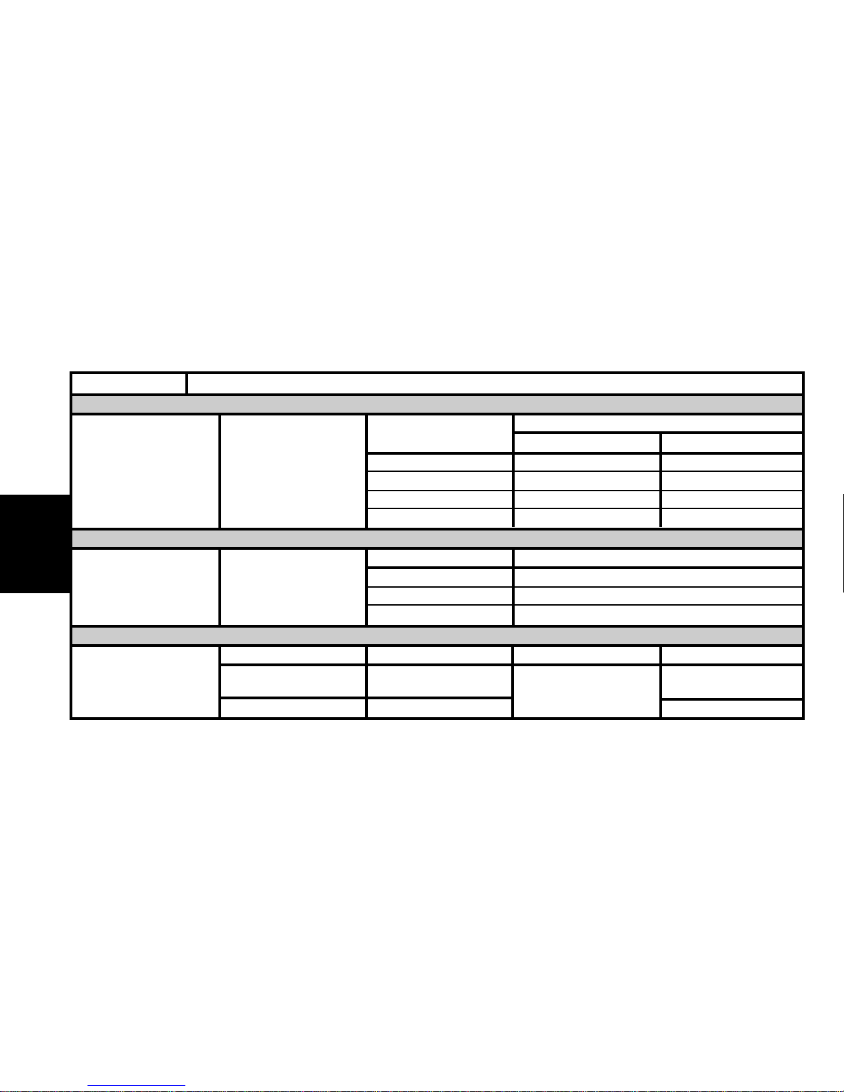
42
GENERAL
Engine coolant fluid
LUBRICANTS - TOTAL recommended oils
ALL TYPES
Packs
CITROEN reference
GLYSANTIN G 33 REVCOGEL 2000
CITROEN Fluid 2 litres 9979 70 9979 72
All countries
Protection : - 35°C 5 litres 9979 71 9979 73
20 litres 9979 76 9979 74
210 litres 9979 77 9979 75
Synthetic brake fluid
Packs CITROEN reference
All countries CITROEN Fluid
0.5 litre 9979 05
1 litre 9979 06
5litres 9979 07
CITROEN hydraulic circuit fluid
Norm Pack CITROEN reference
All countries
TOTAL LHM PLUS
ISO 7308-7309 ZCP 830 095
Green in colour
1 litre
9979.20 (Scandinavia)
TOTAL FLUIDE LDS Orange in colour 9979.69
Page 46
43
GENERAL
Packs CITROEN reference
Concentrated : 250 ml 9980 33 ZC 9875 953 U 9980 56
All countries
Liquid ready to use: 1 litre 9980 06 ZC 9875 784 U
Liquid ready to use: 5 litres 9980 05 ZC 9885 077 U ZC 9875 279 U
Grease
Norms NLGI (1)
TOTAL MULTIS EP2 2
All countries TOTAL MULTIS COMPLEX EP2 2
TOTAL MULTIS N4128 1
TOTAL SMALL MECHANISMS
(1) NLGI = National Lubricating Grease Institute.
WARNING: TOTAL LDS fluid cannot be blended with TOTAL LHM PLUS
WARNING: CITROËN C5 : Use only TOTAL FLUIDE LDS suspension fluid.
Hydraulic circuit rinsing fluid- green in colour
TOTAL HYDRAURINCAGE
Wash/wipe fluid
LUBRICANTS - TOTAL recommended oils
ALL TYPES
All countries
All countries
Page 47
44
GENERAL
ENGINE OIL CONSUMPTION
I-Oil consumption depends on :
- the engine type.
- how run-in or worn it is.
- the type of oil used.
- the driving conditions.
II - An engine can be considered RUN-IN after:
- 3.000 miles (5.000 km) for a PETROL engine.
- 6.000 miles (10.000 km) for a DIESEL engine.
III - MAXIMUM PERMISSIBLE oil consumption for a RUN-IN engine.
- 0.5 litres per 600 miles (1.000 km) for a PETROL engine
- 1 litre per 600 miles (1.000 km) for a DIESEL engine.
DO NOT WORK BELOW THESE VALUES.
IV - OIL LEVEL : The level should NEVER be above the MAX. mark on the dipstick after changing or topping up the oil.
- This excess oil will be used up rapidly.
- It will reduce the engine output and adversely affect the operation of the air circuits and gas recycling.
ALL TYPES
Page 48
45
ENGINE
ENGINE SPECIFICATIONS
ALL TYPES
Engines : HDZ - HFX - KFX – KFW – NFT – NFV – NFU - NFX
Petrol
All Types
1.1i 1.4i 1.6i 1.6i 16V
Engine type
Cubic capacity (cc)
Bore / Stroke
Compression ratio
Power ISO or EEC KW - rpm
Power DIN (HP - rpm)
Torque ISO or EEC (m.daN - rpm)
HDZ HFX KFX KFW NFT NFV NFU NFX
1124 1360 1587
72/79 75/77 78.5/82
9.7/1 10.5/1 10.2/1 10.5/1 11.1 10.8/1
44.1-6200 44.1-5500 55-5500 72-5700 70-5700 80-5800 87-6600
60-6200 60-5500 75-5500 98-5700 95-5700 11-5800 120-6600
8.75-3800 9.4-3500 11.1-3400 13.5-3500 13.5-3000 14.7-4000 14.5-5200
Page 49
46
ENGINE
Engine type
Cubic capacity (cc)
Bore / Stroke
Compression ratio
Power ISO or EEC KW - rpm
Power DIN (HP - rpm)
Torque ISO or EEC (m.daN - rpm)
ENGINE SPECIFICATIONS
ALL TYPES
Engines : LFX – 6FZ - RFN - RFS
Petrol
All Types
1.8i 1.8i 16V 2.0i 16V
LFX 6FZ RFN RFS
1761 1749 1997 1998
83/81.5 82.7/81.4 85/88 86/86
9.5/1 10.8/1 10.8/1
66-5000 85-5500 99-6000 12-6500
90-5000 115-5500 136-6000 167-6500
14.7-2600 16.3-4000 19-4100 19.3-5500
Page 50
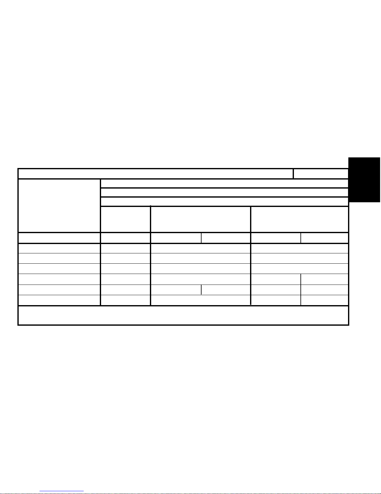
47
ENGINE
Engine type
Cubic capacity (cc)
Bore / Stroke
Compression ratio
Power ISO or EEC KW - rpm
Power DIN (HP - rpm)
Torque ISO or EEC (m.daN - rpm)
ENGINE SPECIFICATIONS
ALL TYPES
Engines : VJX - WJZ – WJY – RHY - RHZ
Diesel
All Types
1.5 D 1.9 D 2.0 HDi
VJX WJZ WJY RHY RHZ
1527 1868 1997
77/82 82.2/88 85/88
23/1 23/1 17.6/1
42-5000 51-4600 66-4000 80-4000
58-5000 70-4600 71-4600 90-4000 110-4000
9.5-2250 12.5-2500 20.5-1900 25-1750
Page 51
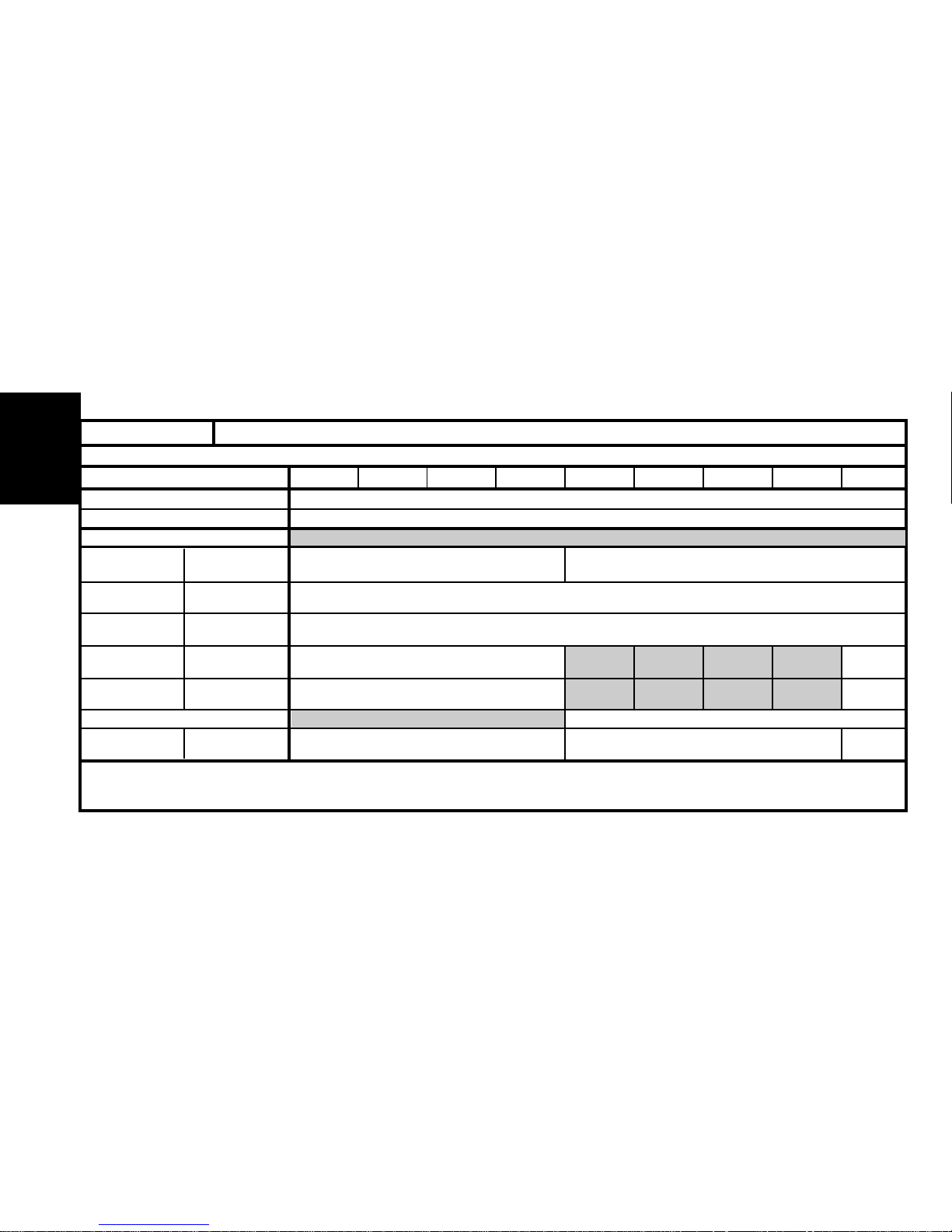
48
ENGINE
SPECIAL FEATURES - TIGHTENING TORQUES ( m.daN )
Engine type HDZ HFX KFW KFX NFT NFV NFX NFU VJX
Maximum permissible bow
0.05
Gasket surface regrinding
- 0.20
Crankshaft
bearing screws
Connecting rod
screws
Flywheel
screw
Crankshaft
pinion screw
Camshaft pulley
screw
Camshaft hubs
Camshaft hub
screw
CYLINDER HEAD (mm)
TIGHTENING TORQUES ( m.daN)
ALL TYPES
Pre-tightening
Angular tightening
Tightening
Tightening
Pre-tightening
Angular tightening
Pre-tightening
Angular tightening
Tightening
2 ± 0.2 2 ± 0.2
45° 50°±5°
3.8 ± 0.4
6.5 ± 0.7
10 ± 1
7 ± 0.7
45°±4°
8 ± 0.8
4 ± 0.4
20°±2°
8 ± 0.8
1 ± 0.1 2.5 ± 0.2
Page 52
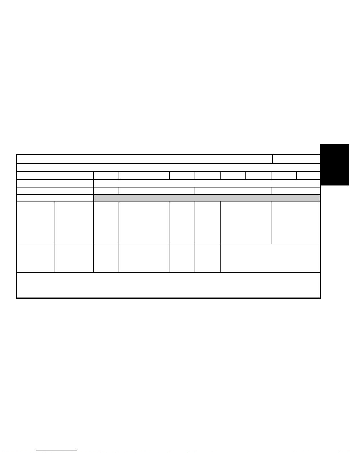
49
ENGINE
SPECIAL FEATURES - TIGHTENING TORQUES ( m.daN )
Engine type LFX 6FZ RFN RFS WJZ WJY RHY RHZ
Maximum permissible bow 0.05 0.03
Gasket surface regrinding - 0.20 - 0.30 - 0.20 - 0.40
Crankshaft
bearing screws
Connecting
rod screws
CYLINDER HEAD (mm)
TIGHTENING TORQUES ( m.daN)
ALL TYPES
Pre-tightening
Slackening
Tightening
Angular
tightening
Tightening
Pre-tightening
Slackening
Tightening
Angular
tightening
5.5 ± 0.5
4 ± 0.4
2± 0.2
70°±7°
(1) Ø 11 : 1 ± 0.1
(2) Ø 6 : 1 ±0.1
Ø 11 (only)
Ø 11 to 1 ± 0,1
then to 2 ± 0,1
Ø 11 to 70° ± 5°
Ø 6 to 1 ± 0,1
1 ± 0.1
180° (1/2 turn)
2.3 ± 0.2
46°±5°
2 ± 0.1
60°±6°
2.3 ± 0.2
46° ±4.6°
8.5 ± 0.8
4 ± 0.4
2± 0.2
70°±7°
7 ± 0.7
2.5 ± 0.3
60°±6°
2 ± 0.2
70°±7°
Page 53
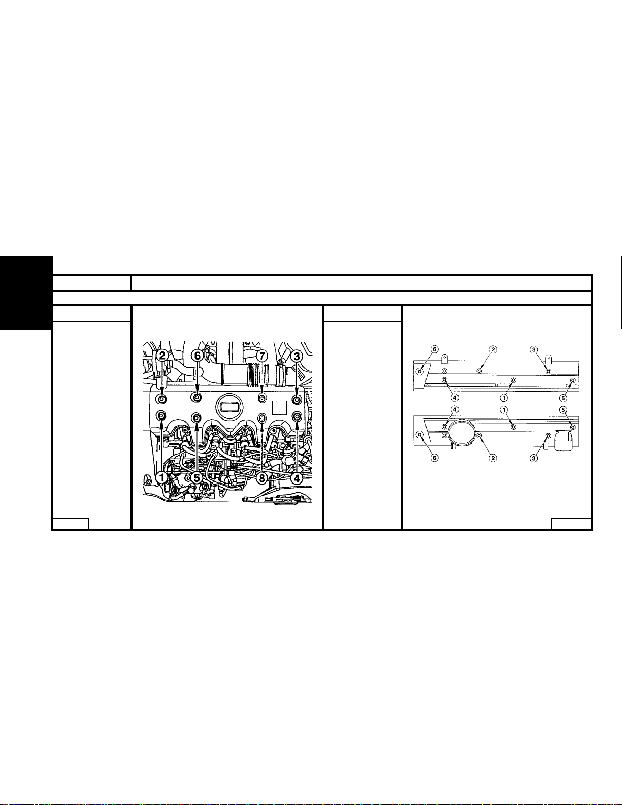
50
ENGINE
SPECIAL FEATURES - TIGHTENING TORQUES ( m.daN )
Engines : RFS - VJX
SAXO
VJX
- Pre-tighten 0.4
- Tighten to 0.7
XSARA
RFS
- Pre-tighten 0.5
- Tighten to 1
TUD - XU
B1DP03BC B1DP01YD
Page 54
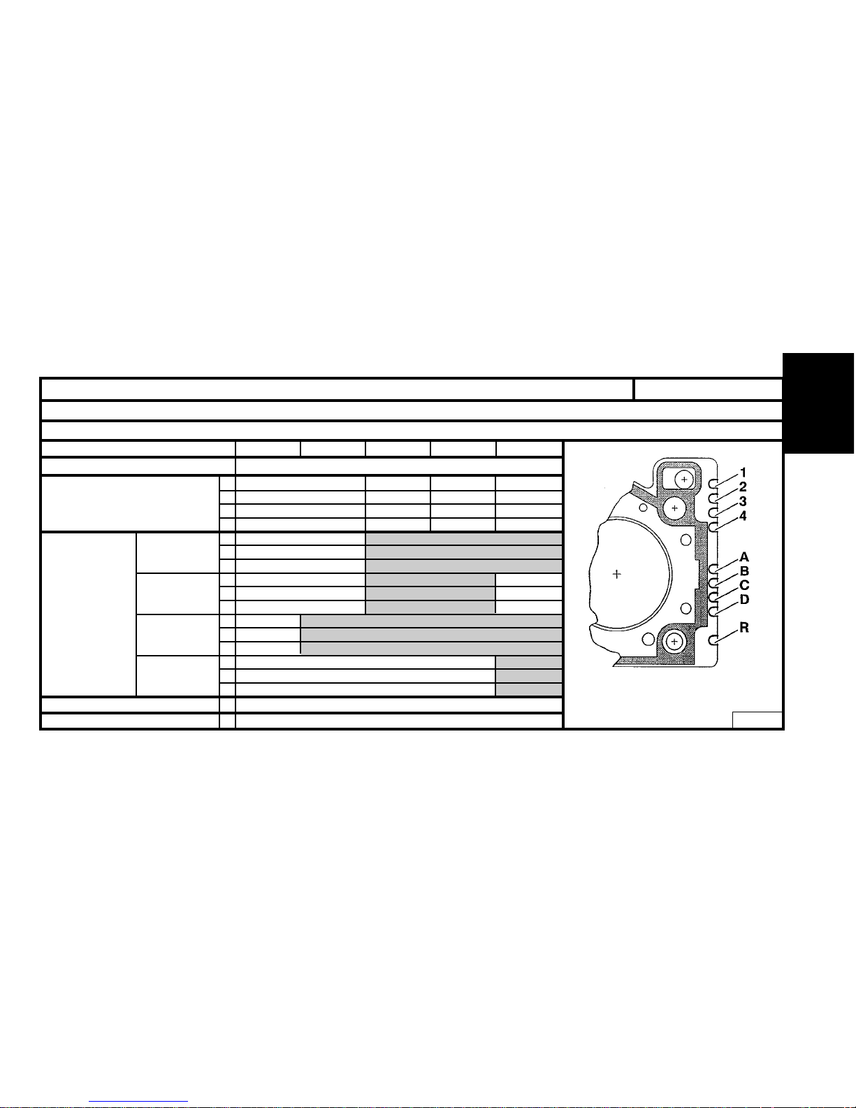
51
ENGINE
CYLINDER HEAD
TU - TUD- All Types
Engines : HDZ - HFX - KFW - KFX - NFT - NFV - NFX - NFU - VJX
Identification of the cylinder head gasket
Engine type
Identification marks
(Notch on cylinder head gasket)
*
HDZ - HFX KFW - KFX NFT - NFV NFX - NFU VJX
1
2
3
4
A
B
D
A
B
D
A
B
D
A
B
D
C
R
0
(Standard gasket) - 1 (Repair gasket)
0 (With asbestos ) - 1 (Without asbestos)
0
0
1
1
0
1
0
1
1
0
0
0
1111
0011
0011
0110
1
1
0
CURTY
MEILLOR
ELRING
REINZ
Material
Repairs
Suppliers
Thickness
*
0 = Without notch
1 = One notch
B1BP10KC
Page 55
52
ENGINE
TU - TUD - All Types
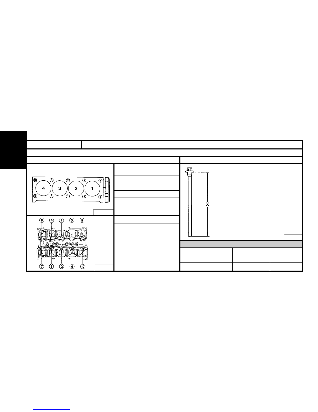
CYLINDER HEAD (continued)
Engines : HDZ – HFX – KFX - KFW - NFT – NFV - NFX – NFU – VJX
Cylinder head tightening (m.daN) Cylinder head bolts
X = MAXIMUM reusable length
Note : Oil the threads and under the heads
of the cylinder head bolts.
(Use engine oil or Molykote G Rapid Plus).
- Pre-tightening 2
- Angular tightening 260° ± 5°
- Pre-tightening 2
- Angular tightening 240° ± 5°
- Pre-tightening 4
- Angular tightening 300° ± 5°
B1DP059C
B1BP10LC
NFU - NFX
VJZ
HDZ-HFX-KFX-KFW
NFV-NFT
HDZ-HFX-KFX-KFW
NFV-NFT
X= 175.5 ± 0.5 mm X = 197.1 mm X = 122.6 mm
VJX
NFU-NFX
B1DP13NC
Page 56
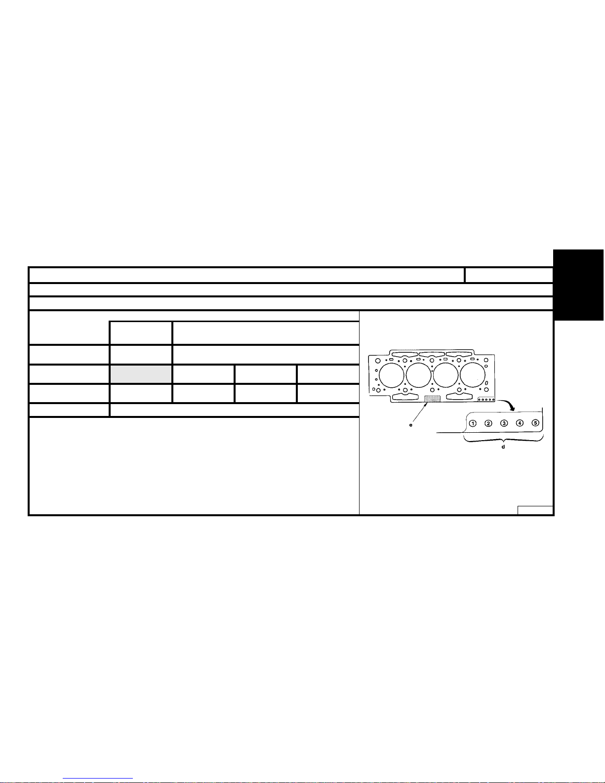
53
ENGINE
XU - All Types
CYLINDER HEAD
Engine : 6FZ
Identification of the cylinder head gasket
B1DP183D
Nominal
dimension
Repair dimension
2 – 4 – 54 – 5
R1 R2 R3
10.8
Gasket thickness
(mm)
Supplier MEILLOR
Marking zone
"e"
Marking zone
"d"
1.1 1.3
Marking
" d " Marking zone
" e " Marking zone
NOTE : 3 layer metallic gasket.
Page 57
54
ENGINE
EW 10 - All Types
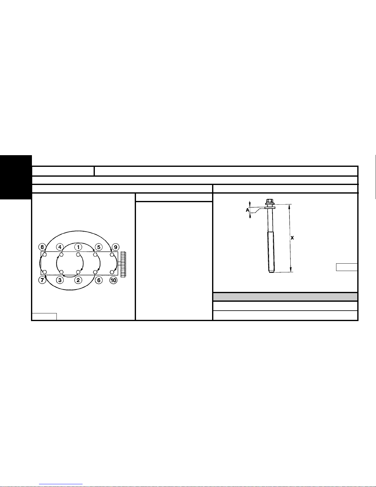
CYLINDER HEAD (continued)
Engine : 6FZ
X = MAXIMUM reusable length
NOTE : Oil the threads and
under the heads of the cylinder
head bolts.
(Use engine oil or Molykote G
Rapid Plus).
Pre-tightening 1.5 ± 0.2
Tightening 5 ± 0.2
Loosening 360 ° (1 turn)
Tightening 2 ± 0.2
Angular tightening 285° ± 5°
B1DP16FC
B1DP05BC
6FZ
6FZ
X= 147 mm
Cylinder head tightening (m.daN) Cylinder head bolts
A = Washer thickness: 4 ± 0.2 mm.
X = Length under heads of new bolts = 144.5 ± 0.5 mm.
Page 58
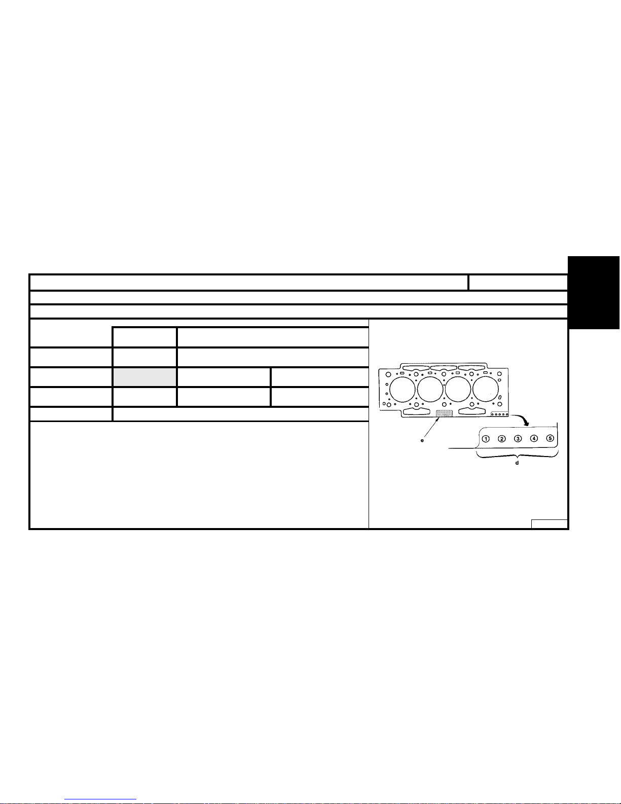
55
ENGINE
EW 10 - All Types
CYLINDER HEAD (continued)
Engine : RFN
Identification of the cylinder head gasket
B1DP183D
Nominal
dimension
Repair dimension
2 – 4 – 54 – 5
R1 R2
1.10.8
Gasket thickness
(mm)
Supplier MEILLOR
Marking zone
"e"
Marking zone
"d"
1.4
Multilayer metallic gasket
Page 59
56
ENGINE
CYLINDER HEAD (continued)
Engine : RFN
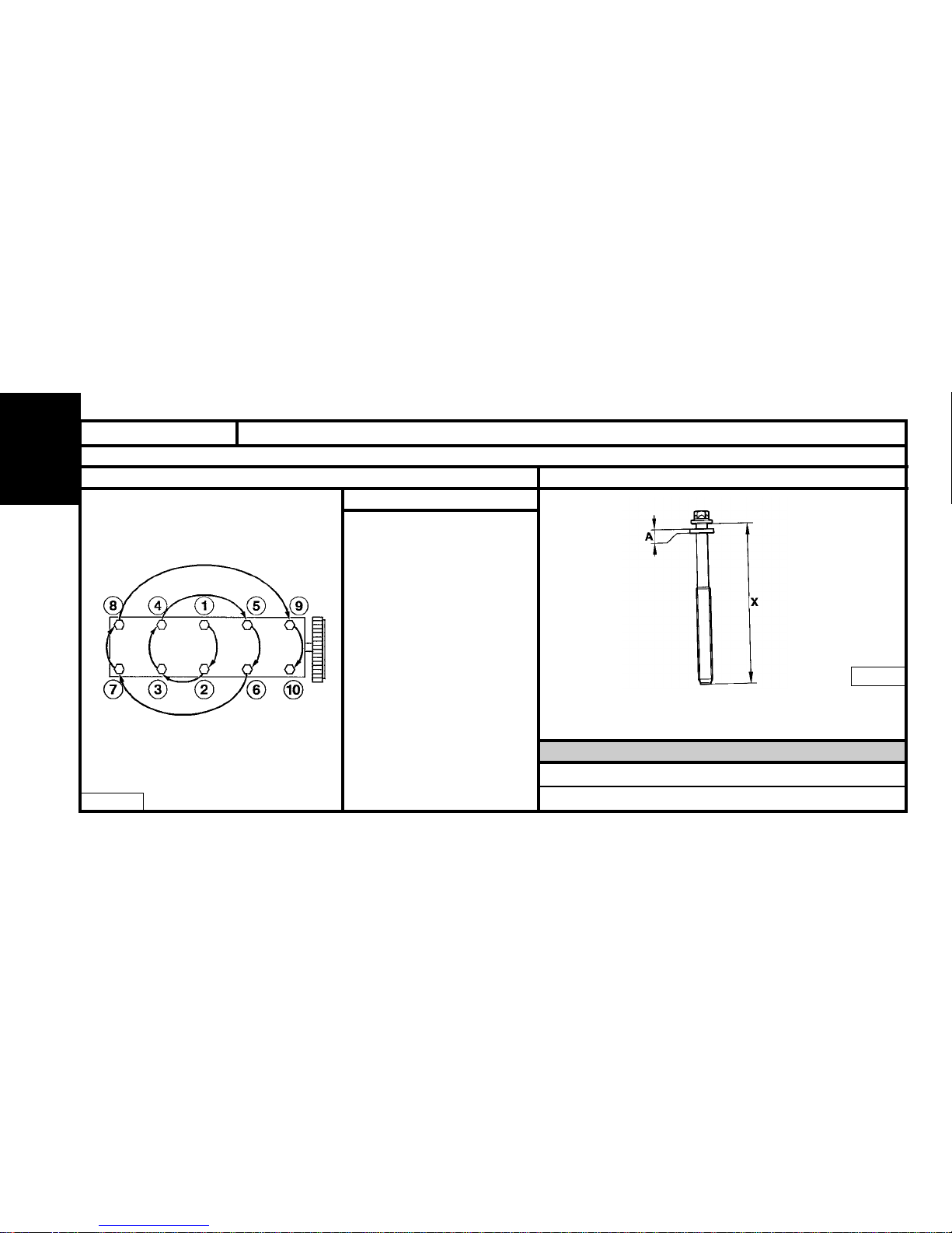
X = MAXIMUM reusable length
NOTE : Oil the threads and
under the heads of the cylinder
head bolts.
(Use engine oil or Molykote G
Rapid Plus).
Pre-tightening 1.5 ± 0.1
Tightening 5 ± 0.1
Loosening 360°± 2°
Tightening 2 ± 0.75
Angular tightening 285° ± 5°
B1DP16FC
B1DP05BC
RFN
RFN
X= 147 mm
Cylinder head tightening (m.daN) Cylinder head bolts
A = Washer thickness : 4 ± 0.2 mm.
X = Length under heads of new bolts = 144.5 ± 0.5 mm.
EW 10 - All Types
Page 60
57
ENGINE
CYLINDER HEAD
XU - All Types
Engines : LFX - RFS
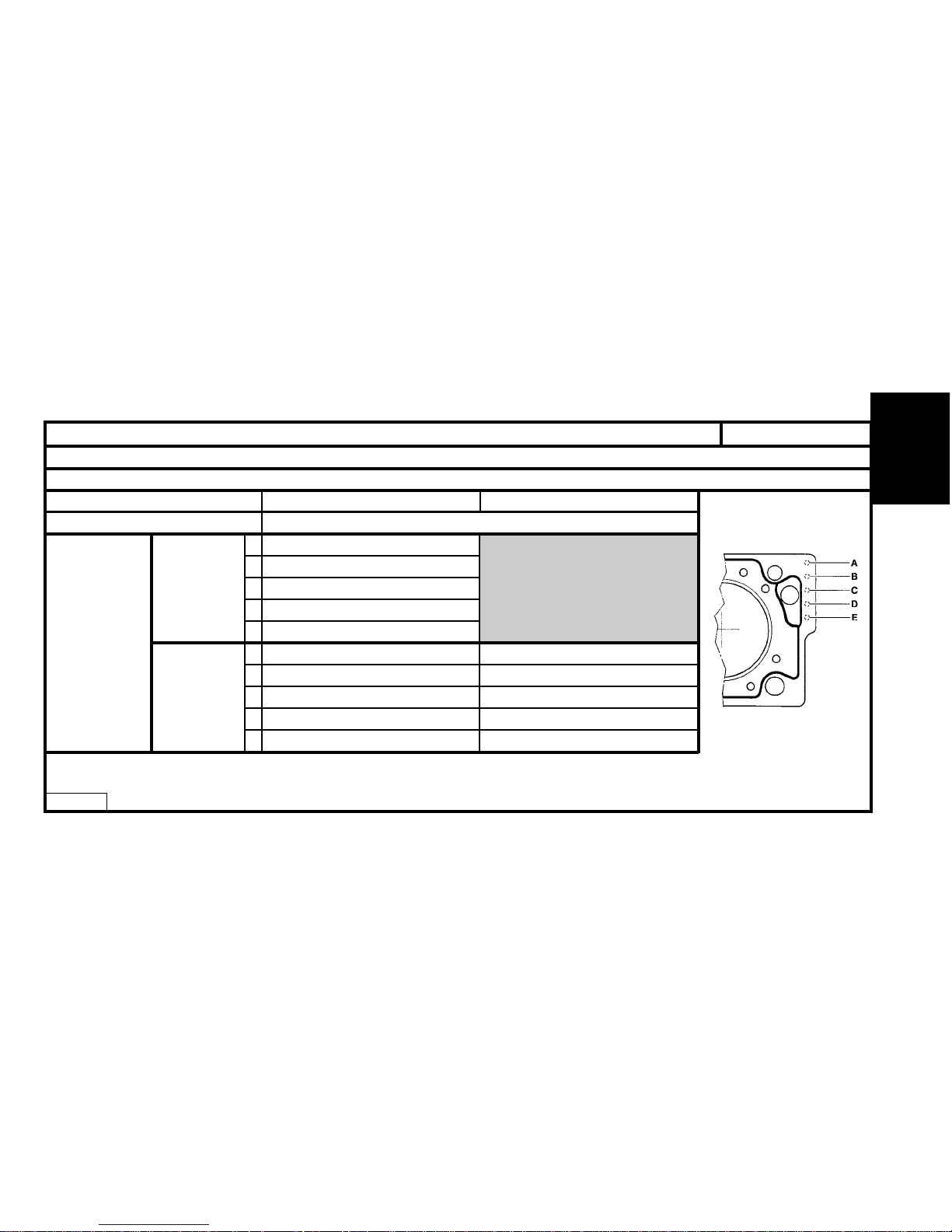
Identification of the cylinder head gasket
Engine type
Identification marks
(Notch on cylinder head gasket) *
LFX
RFS
A
1
B
0
C
0
D
0
E
0
A
01
B
10
C
01
D
00
E
00
CURTY
MEILLOR
Suppliers
*
0 = Without notch
1 = One notch
B1BP004C
Page 61
58
ENGINE
CYLINDER HEAD (continued)
Engines : LFX - RFS
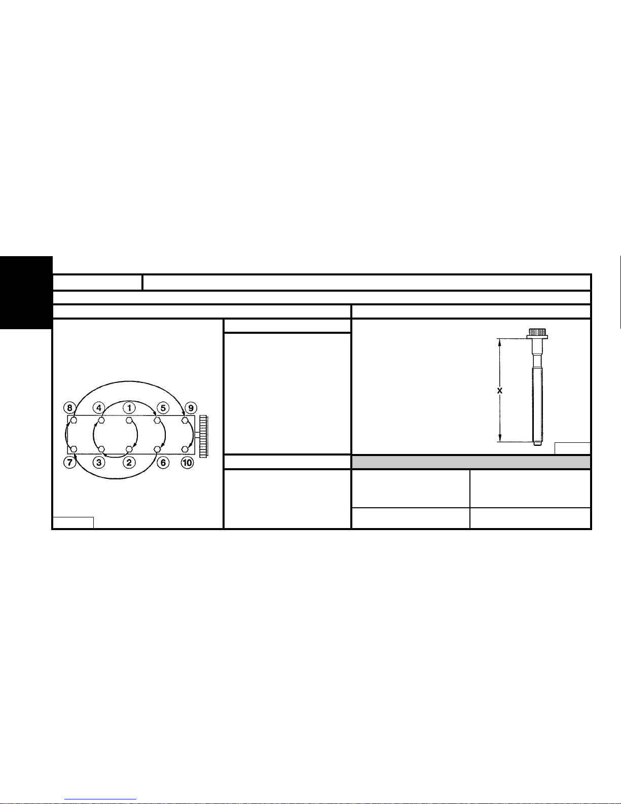
X = MAXIMUM reusable length
Note : Oil the threads and
under the heads of the cylinder
head bolts.
(Use engine oil or Molykote G
Rapid Plus).
- Pre-tightening 3.5
- Loosening NO
- Tightening 7
- Angular tightening 160°
- Pre-tightening 6
- Loosening YES
- Tightening 2
- Angular tightening 300°
B1DP13PC
B1DP05BC
RFS
LFX
LFX
RFS
171.5 mm 112 mm
Cylinder head tightening (m.daN) Cylinder head bolts
XU - All Types
Page 62
59
ENGINE
DW8 - All Types
CYLINDER HEAD
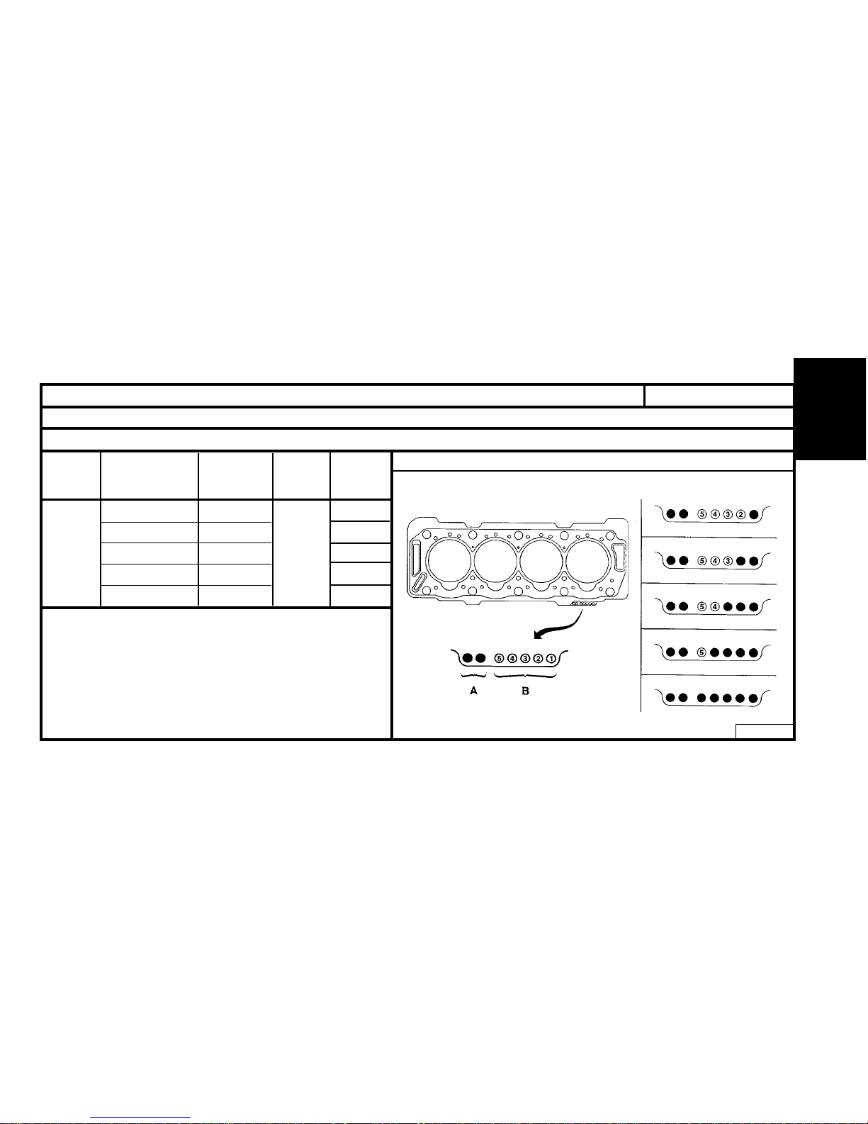
Identification of the cylinder head gasket
Number
of holes
at B
Number
of holes
at A
Thickness
(mm)
± 0.04
Engine
type
Piston
stand-proud
(mm) (*)
0.51 to 0.55 1.26 1
0.55 to 0.59 1.30 2
0.59 to 0.63 1.34 3
0.63 to 0.67 1.38 4
0.67 to 0.71 1.42 5
WJZ
WJY
(A) = Engine identification.
(B) = Thickness identification.
(
*
) = Take the highest piston as a reference point.
B1DP14QD
Engine : WJZ - WJY
WJZ - WJY
2
Page 63
60
ENGINE
DW10 - All Types
CYLINDER HEAD
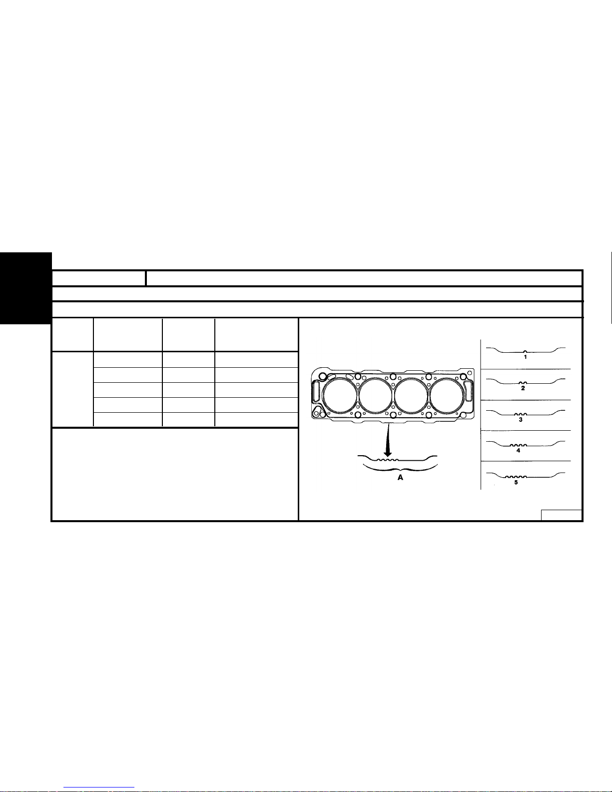
Identification of the cylinder head gasket
Number
of notches
at A
Thickness
(mm)
Plaque
Engine
Piston
stand-proud
(mm)
0.47 to 0.605 1.30 ± 0.06 1
0.605 to 0.655 1.35 ± 0.06 2
0.655 to 0.705 1.40 ± 0.06 3
0.705 to 0.755 1.45 ± 0.06 4
0.755 to 0.83 1.50 ± 0.06 5
RHY
RHZ
B1DP15AD
Engines : RHY - RHZ
Page 64
61
ENGINE
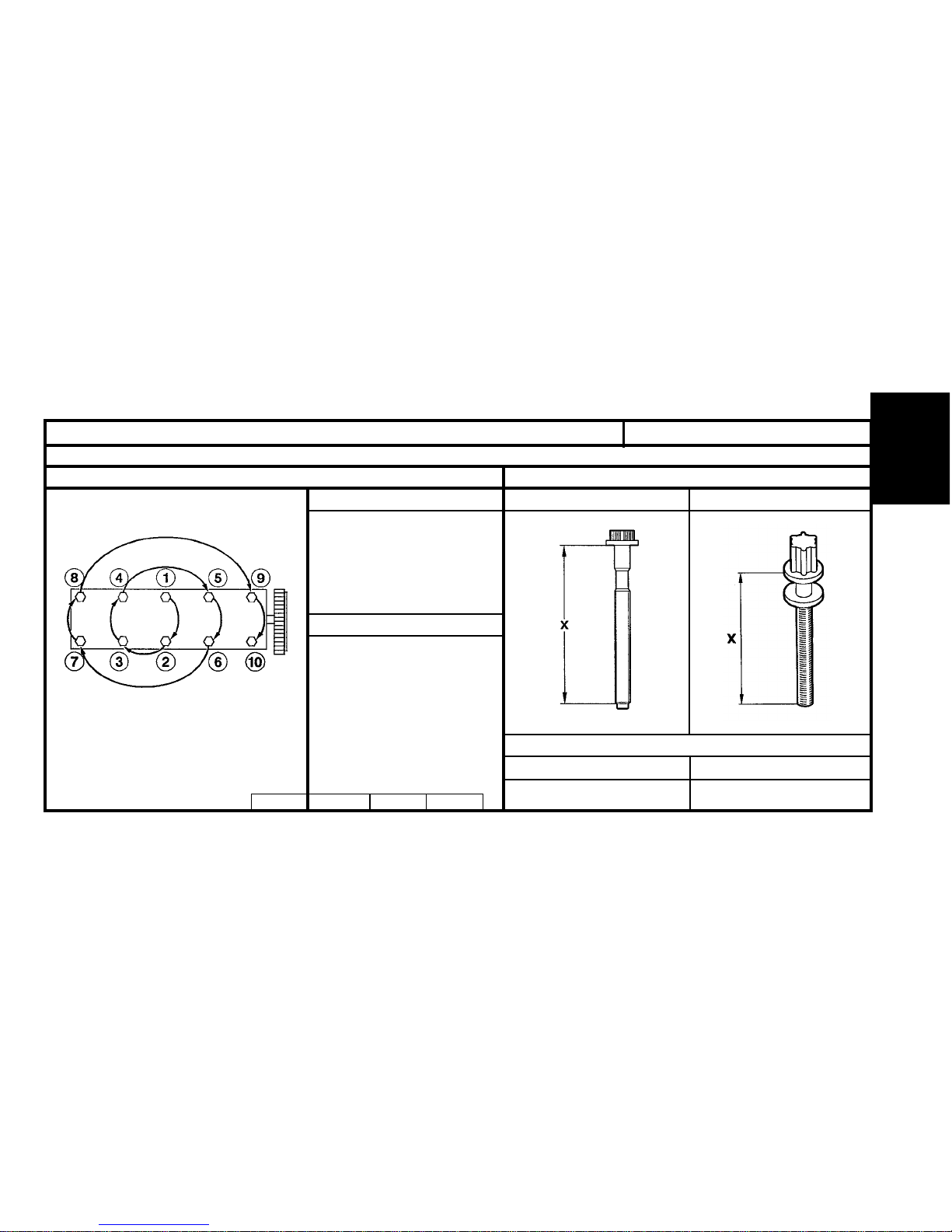
XUD - DW8 - DW10 - All TypesCYLINDER HEAD (continued)
Engines : WJZ – DHY - RHY
X = MAXIMUM reusable length
Note : Oil the threads and under the
heads of the cylinder head bolts.
(Use engine oil or Molykote G Rapid Plus).
- Pre-tightening 2
- Tightening 6
- Angular tightening 220°
- Pre-tightening 2
- Tightening 6
- Angular tightening 180°
B1DP14NC
B1DP15EC
B1DP13PC
RHY - RHZ
WJZ - WJY
WJZ - WJY RHY - RHZ
125.5 mm
133.3 mm
Cylinder head tightening (m.daN) Cylinder head bolts
WJZ - WJY RHY - RHZ
B1DP05BC
Page 65
62
ENGINE
Tools
ALL TYPES
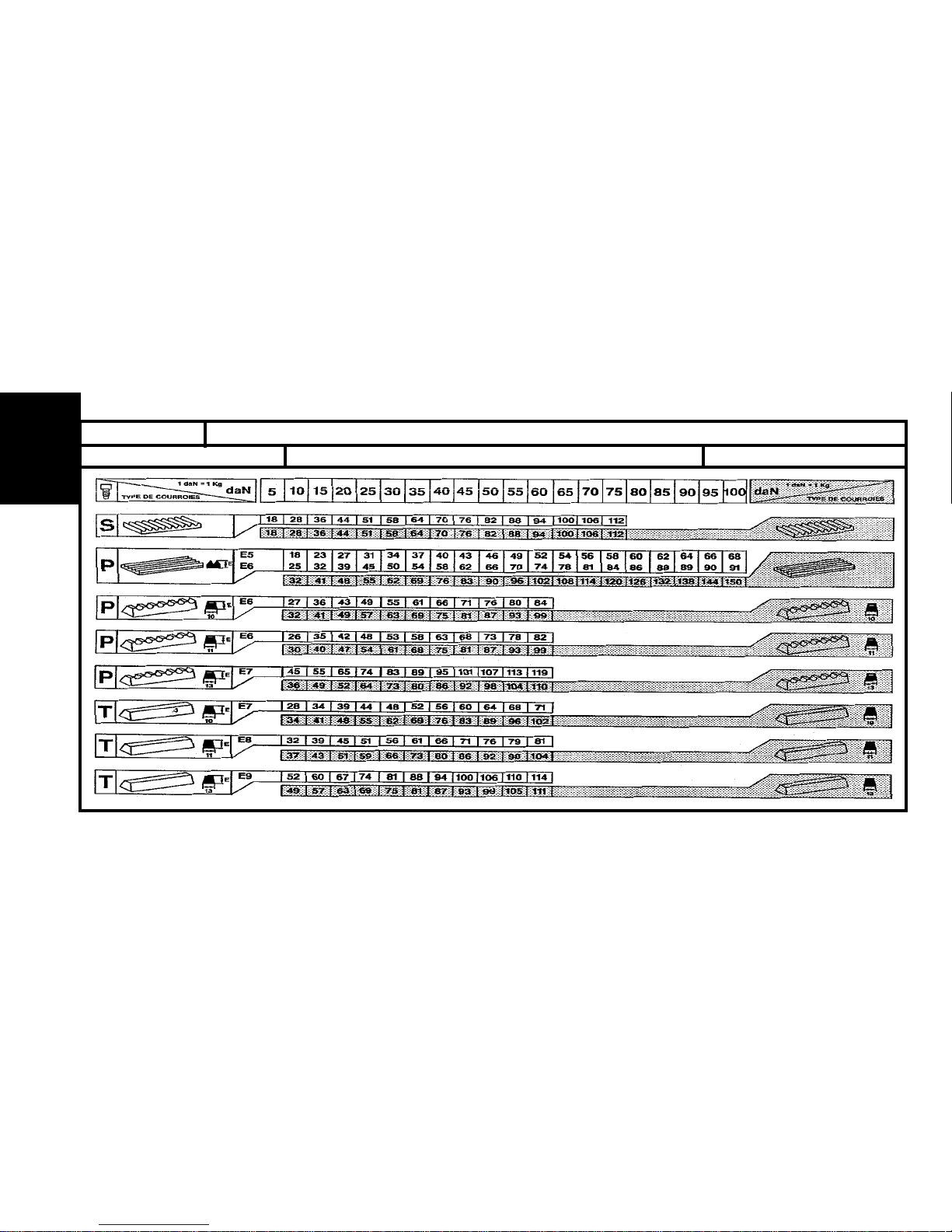
BELT TENSION/SEEM UNITS CORRESPONDENCE TABLE
! 4099-T (C.TRONIC.105)
4122-T (C.TRONIC.105.5)
!
!
!
Page 66
63
ENGINE
AUXILIARY EQUIPMENT DRIVE BELT 2002
ALL TYPES
Engines : All Types Petrol and Diesel
TOOLS
- Belt tension measuring instrument : 4122-T. (C.TRONIC 105.5)
- WARNING : If using tool 4099-T (C.TRONIC 105), refer to the correspondence table on page 90.
ESSENTIAL.
- Before refitting the auxiliary equipment drive belt, check that:
1) The roller(s) rotate freely (no play or stiffness).
2) The belt is correctly engaged in the grooves of the various pulleys.
Page 67
64
ENGINE
SAXO
AUXILIARY EQUIPMENT DRIVE BELT
Without air conditioning With air conditioning
- Fit the tool 4122-T.
- Tighten the tensioning screw (3)
to obtain :
55 ± 3 SEEM units.
- Tighten the screws (2) and (1).
- Remove the tool 4122-T.
- Fit the tool 4122-T.
- Tighten the tensioning screw (5)
to obtain :
120 ± 3 SEEM units.
- Tighten the screws (6) and (4).
- Remove the tool 4122-T.
B1BP10VC B1BP10XCB1BP10UC B1BP10WC
Engines : HDZ – HFX – (KFX – KFW – NFT) saxo
Page 68
65
ENGINE
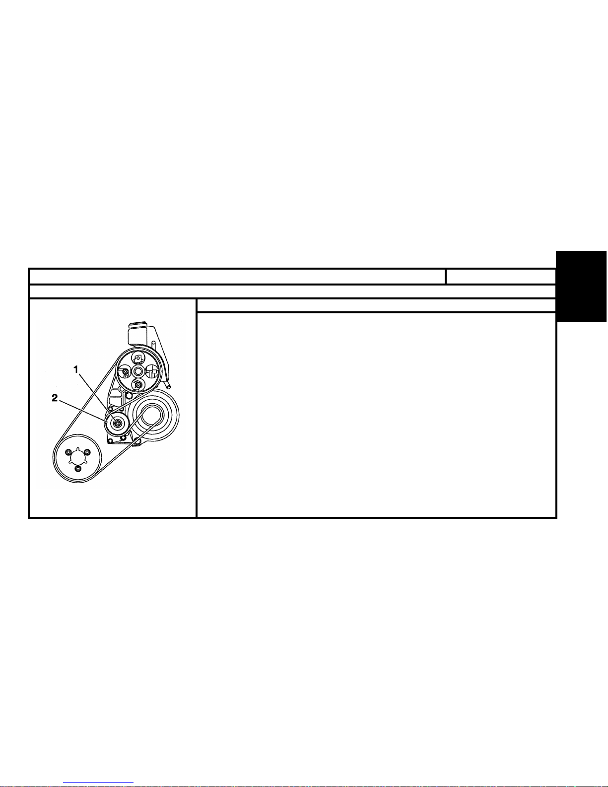
XSARA PICASSO
AUXILIARY EQUIPMENT DRIVE BELT
Engine : NFV (Xsara Picasso)
Without air conditioning.
Tools.
[1] Plyers for removing plastic pegs : 7504 –T.
[2] Belt tension measuring instrument : 4122 –T.
[3] TORX spanner.
Remove.
- Release the central screw (1).tool [3].
- Detension the tensioner roller (2), (flat spanner 27 on flat).
- Remove the belt.
Refit.
- Position the belt.
- Hold the belt in position using the tensioner roller (2).
- Pre-tension the belt 120 SEEM units, tool [2].
- Lock the central screw (1) tool [3].
- Remove the tool [2].
- Rotate the crankshaft 2 to 4 times.
- Check the tension, 120 SEEM units.
- If not, restart the operation.
Page 69
66
ENGINE
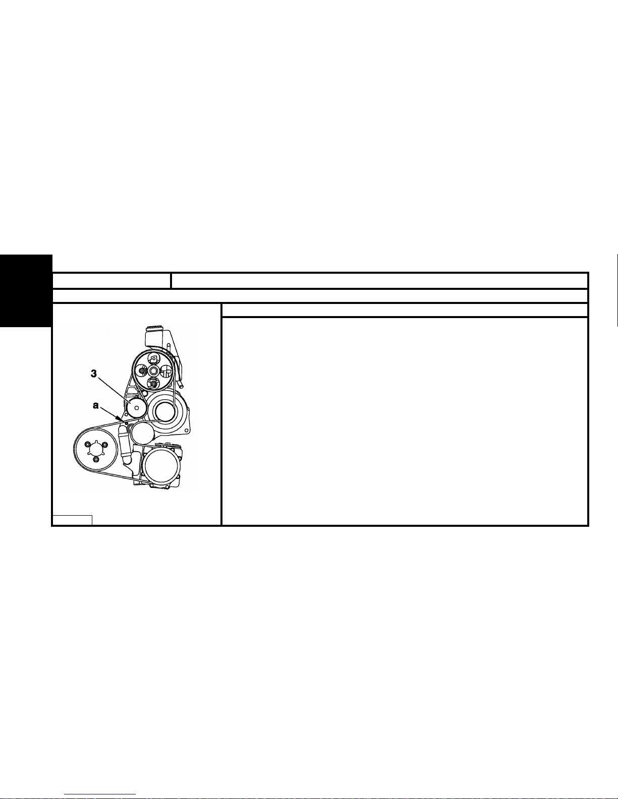
AUXILIARY EQUIPMENT DRIVE BELT
Engine : NFV (Xsara Picasso)
With air conditioning.
XSARA PICASSO
B1BP235C
Tools.
[1] Plyers for removing plastic pegs : 7504 –T.
[2] Belt tension measuring instrument : 4122 –T.
[3] 10 mm square (drain spanner).
[4] TORX spanner.
Remove.
- Detension the automatic tensioner, tool [3].
- Place a Ø 6 mm peg at (a) to immobilise the automatic tensioner.
- Remove the belt
REFIT
- Position the belt
- Detension the automatic tensioner, tool [3].
- Remove the Ø 6 mm peg.
- Release the automatic tensioner.
- Remove the tool [3].
Page 70
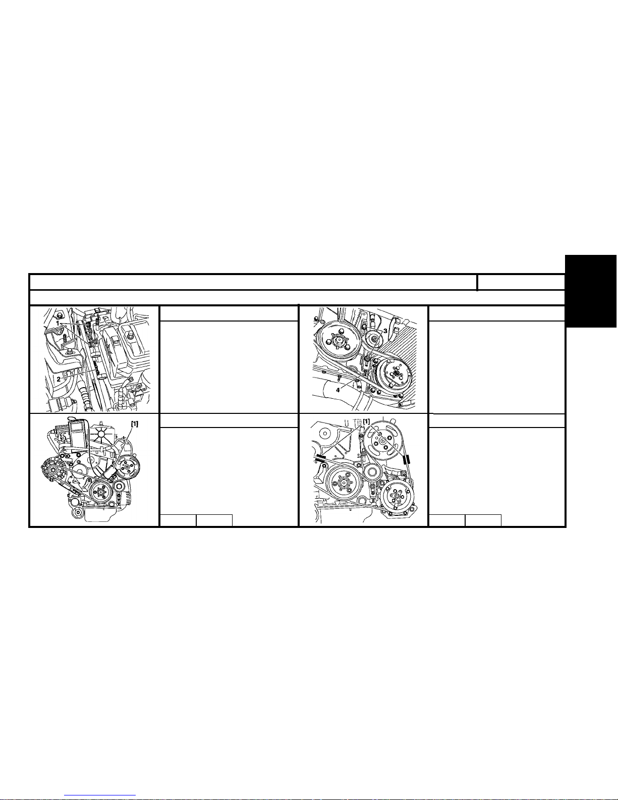
67
ENGINE
[1] Belt tension measuring instrument :
4122-T
- T ension the belt using the screw (2).
- Tension should be :
102 ± 7 unites SEEM.
- Tighten the screws (1).
- New belt
100 SEEM units.
- Reused belt
75 SEEM units.
AUXILIARY EQUIPMENT DRIVE BELT
Alternator
Power-assisted steering Power steering and air con.
With air conditioning.
[1] Belt tension measuring instrument :
4122-T
- T ension the belt using the screw (4).
- Tension should be :
102 ± 7 unites SEEM.
- Tighten the screws (3).
- New belt
100 SEEM units.
- Reused belt
75 SEEM units.
B1BP1B3C B1BP124CB1BP1B2C B1BP122C
Engine : KFW (Xsara)
XSARA
Page 71
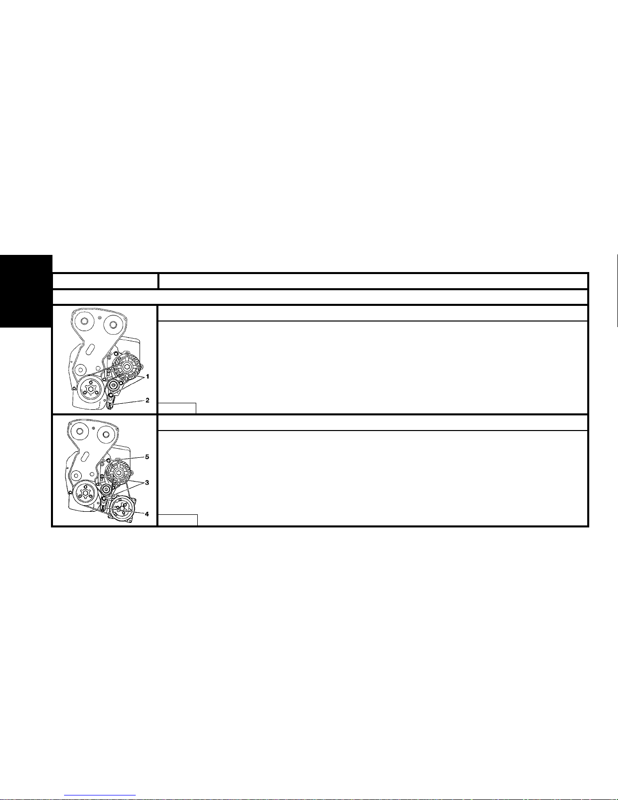
68
ENGINE
AUXILIARY EQUIPMENT DRIVE BELT
SAXO - XSARA
(1) Tensioner roller fixing screw
(2) Tensioning screw
- New belt : 120 SEEM units.
- Reused belt : 86.5 ± 3.5 SEEM units.
(3) Tensioner roller fixing screw
(4) Tensioning screw
- New belt : 120 SEEM units.
- Reused belt : 86.5 ± 3.5 SEEM units.
NOTE : Removal of the tensioner roller makes it necessary to remove the plate with the upper fixing screw (5).
Without air conditioning.
With air conditioning.
B1BP1ANC
B1BP1AMC
Engines : NFX - NFU
Page 72
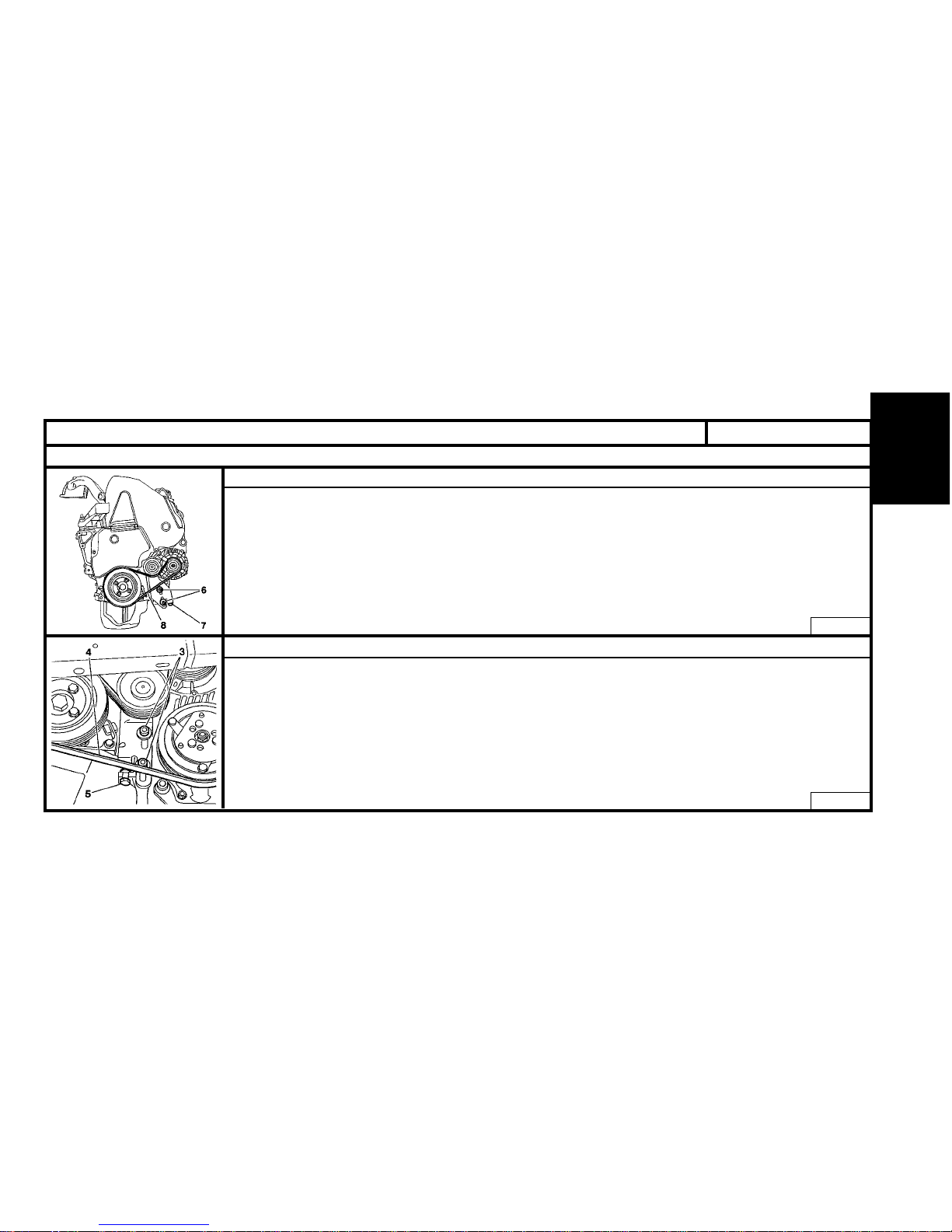
69
ENGINE
AUXILIARY EQUIPMENT DRIVE BELT
- (6) Roller support fixing screw.
- (7) Tensioning screw
- Pre-tension the belt (8) to : 120 SEEM units.
- Rotate the crankshaft by 3 turns (Direction of rotation).
- Adjust the belt (8) tension to : 120 SEEM units.
- Tighten the screws (6) to : 2.5 m.daN.
- Run the engine for 10 min.
- Check the tension.
- (3) Roller support fixing screw
- (5) Tensioning screw
- Pre-tension the belt (4) to : 120 SEEM units.
- Rotate the crankshaft by 3 turns (Direction of rotation).
- Adjust the belt (4) tension to : 120 SEEM units.
- Tighten the screws (3) to : 2.5 m.daN.
- Run the engine for 10 min.
- Check the tension.
Without air conditioning.
With air conditioning.
B1BP11DC
B1BP11EC
Engine : VJX
SAXO- XSARA
Page 73
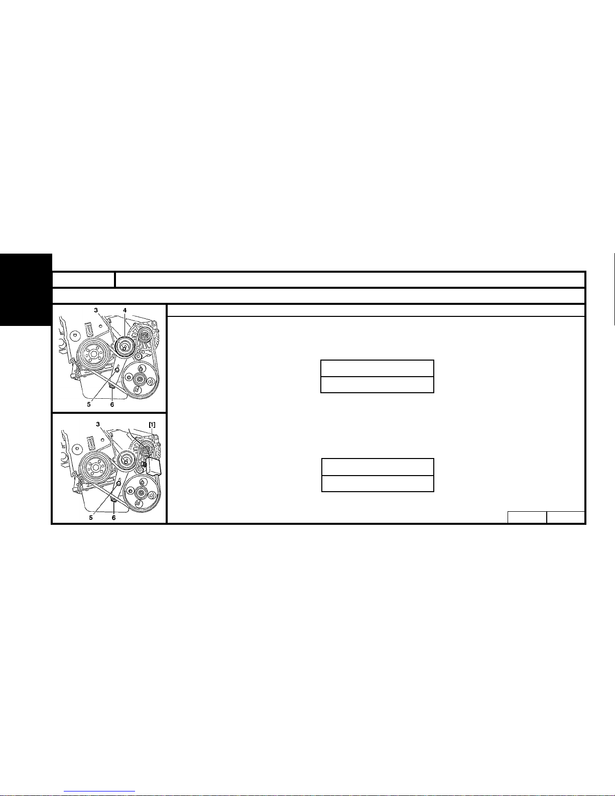
70
ENGINE
XSARA
AUXILIARY EQUIPMENT DRIVE BELT
- (3) and (5) Roller support fixing screws
- (6) Tensioning screw
- Tighten the belt, by loosening the screw (6) to : In SEEM units.
- Tighten the screws (3) and (5).
- Rotate the crankshaft by 4 turns (Direction of rotation).
- Loosen the screws (3) and (5).
- Tighten the belt, by loosening the screw (6) to : In SEEM units.
- Tighten the screws (3) and (5) to 2 m.daN.
Without air conditioning.
B1BP00IC
B1BP00HC
Engine : LFX
LFX
100 ± 10
LFX
115 ± 5
Page 74
71
ENGINE
AUXILIARY EQUIPMENT DRIVE BELT
XSARA
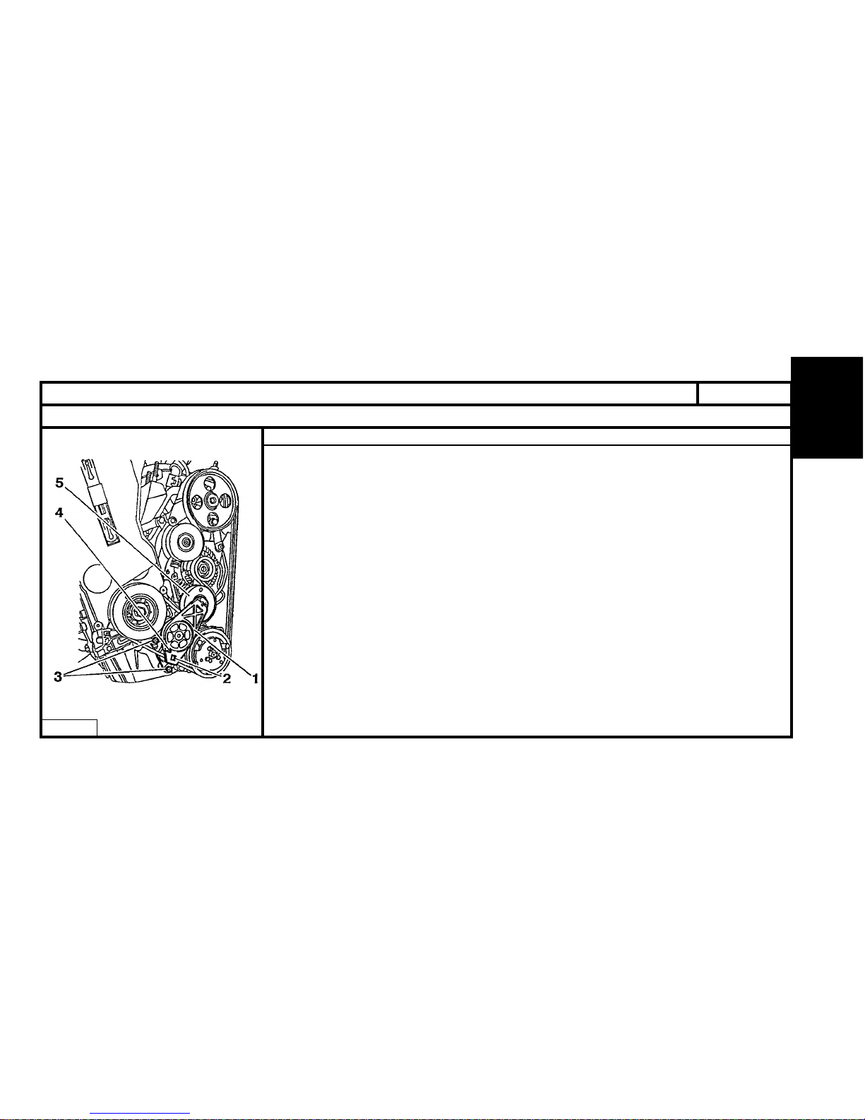
- Fit the drive belt.
- The tensioner roller (1).
- Tighten the screws (3) to 2 m.daN.
- Move the tensioner roller (1) using the tool (9.52 mm square drive (3/8)) at (2), in order to remove
the tool or locking peg (Ø 4 mm) at (4).
- Slowly release the tensioner roller (1) so that the roller (5) presses against the belt.
With air conditioning.
B1BP1HJC
Engines : LFX - RFS
Page 75
72
ENGINE
AUXILIARY EQUIPMENT DRIVE BELT
XSARA
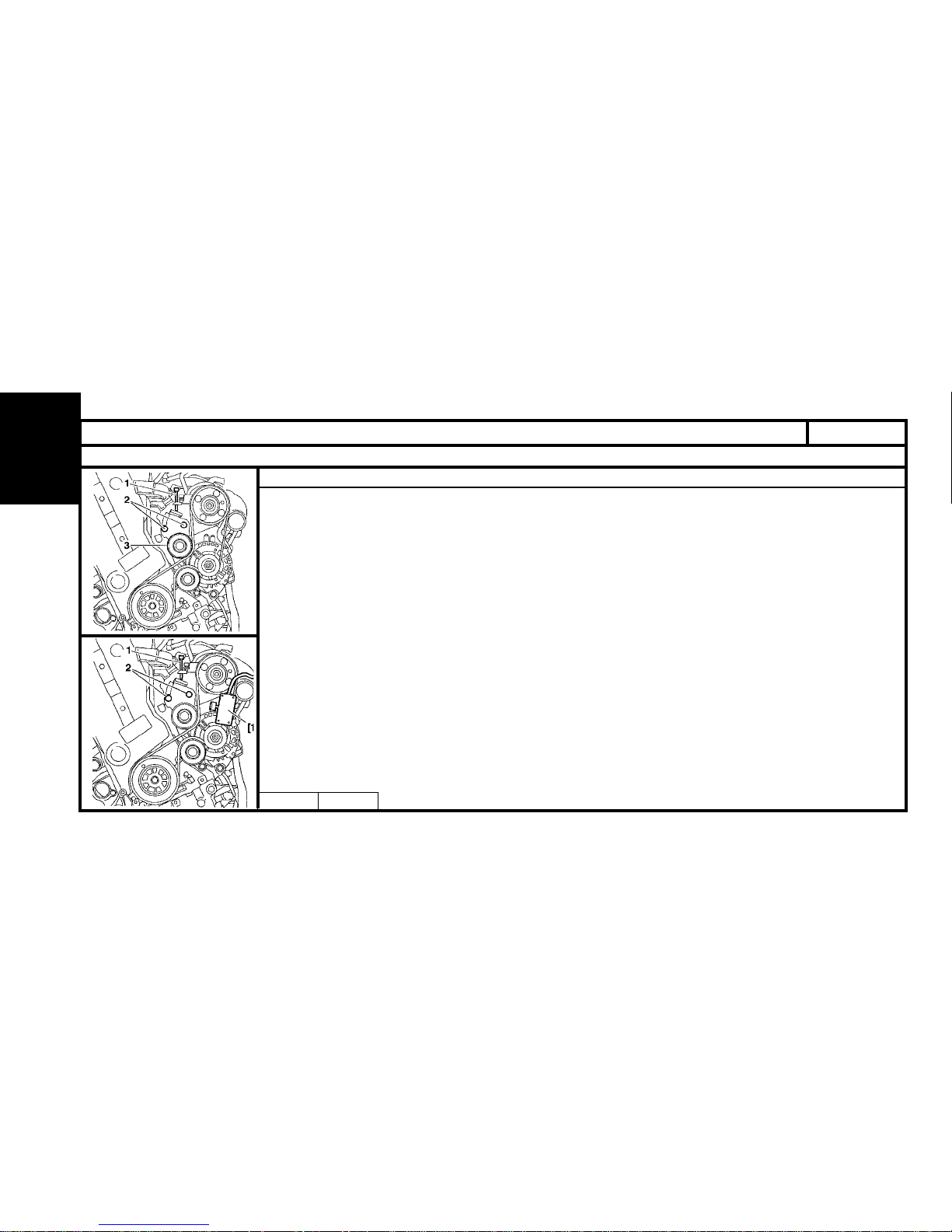
TOOLS
[1] Belt tension measuring instrument 4122-T
- (1) Tensioning screw.
- (2) Roller support fixing screw (3).
- Lightly tighten the screws (2).
- Place the tool [1] on the belt.
- Tension the belt using the screw (1).
• Reused belt 90 SEEM units.
• New belt 120 SEEM units.
- Tighten the screws (2) to 2 m.daN.
- Remove the tool [1].
- Rotate the crankshaft by 3 turns (direction of rotation).
- Check the belt tension using the tool [1], and adjust (if necessary).
Without air conditioning.
B1EP12YC
B1EP12XC
Engine : RFS
Page 76
73
ENGINE
AUXILIARY EQUIPMENT DRIVE BELT
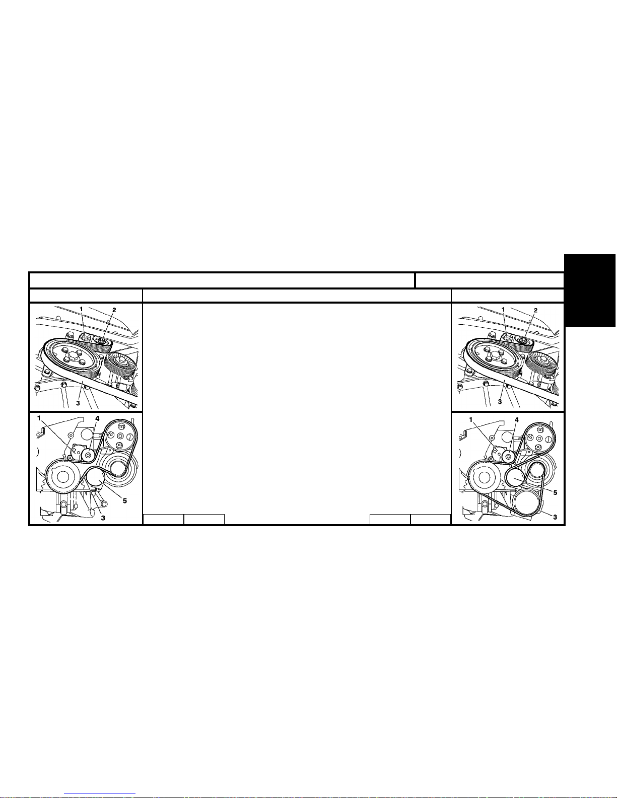
Engines : 6FZ – RFN
Without air conditioning. With air conditioning.
Tools
[1] Plyers for removing plastic pegs 7504-T
Remove the belt.
-Detension the belt (3) by turning the screw (2) of the tensioner roller (1)
(anti-clockwise).
- The screw (2) (WARNING : not left hand screw).
- Remove the belt (3), while keeping the tensioner roller (1) tight.
Refit the belt.
- Refit the belt (3), while keeping the tensioner roller (1) tight.
- Release the tensioner roller (1).
B1BP23PC B1BP23QC B1BP23PC B1BP23RC
XSARA - XSARA PICASSO
Page 77
74
ENGINE
AUXILIARY EQUIPMENT DRIVE BELT
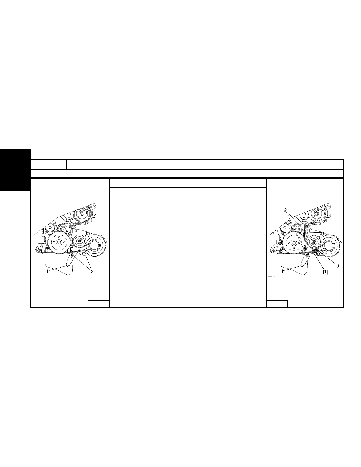
Without power-assisted steering
Tools :
[1] Belt tension measuring instrument 4122-T.
Remove.
- Loosen the screws (2).
- Tighten the screw (1) until it is against its stop.
- Remove the belt.
Refitting.
- Refit the belt.
- Fit the tool [1] on the belt at "d".
- Tighten the screw (1) to obtain : 106 ± 10 SEEM units.
- Tighten the screws (2) to 2 m.daN.
- Remove the tool [1].
B1BP1SECB1BP1SDC
Engines : WJX
XSARA
Page 78
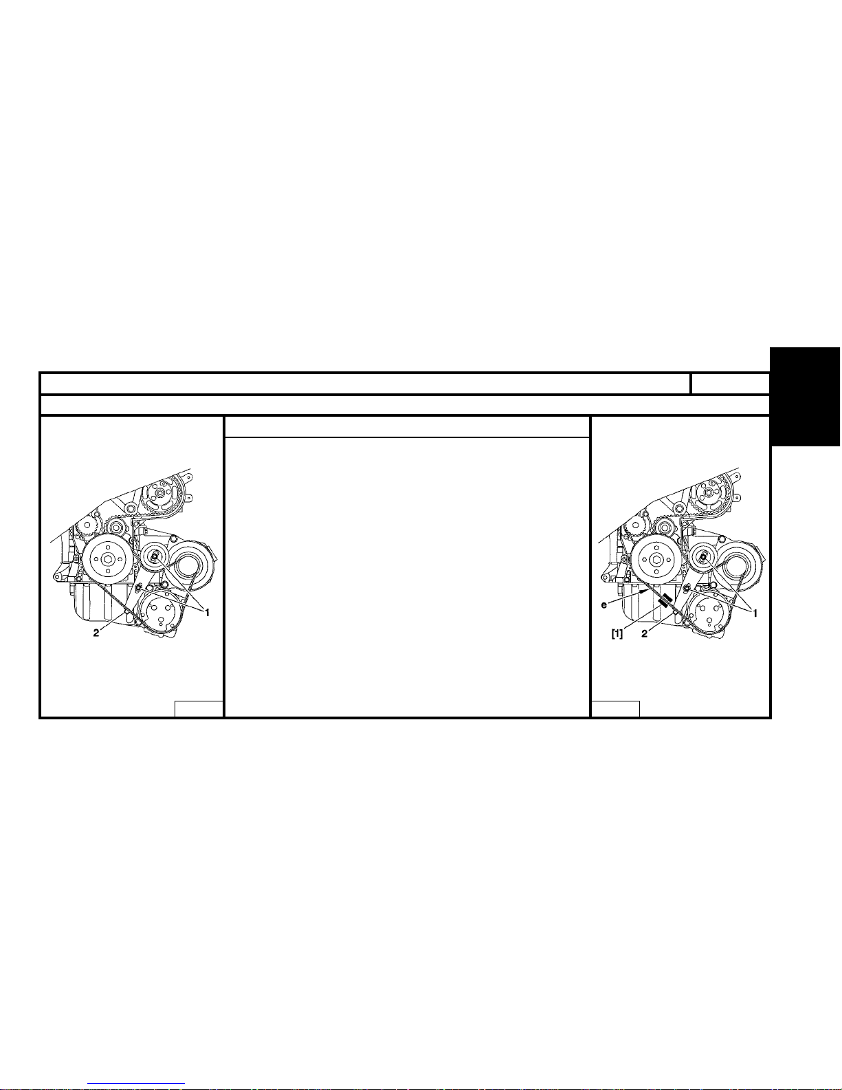
75
ENGINE
XSARA
AUXILIARY EQUIPMENT DRIVE BELT
Without power-assisted steering, with air conditioning
Tools :
[1] Belt tension measuring instrument : 4122-T.
Remove.
- Loosen the screws (1).
- Tighten the screw (2) until it is against its stop.
- Remove the belt.
Refiting.
- Refit the belt.
- Fit the tool [1] at "e".
- Tighten the screw (2) to obtain : 106 ± 10 SEEM units.
- Tighten the screws (1) to 2 m.daN.
- Remove the tool [1].
B1BP1SGCB1BP1SFC
Engines : WJZ - WJY
Page 79
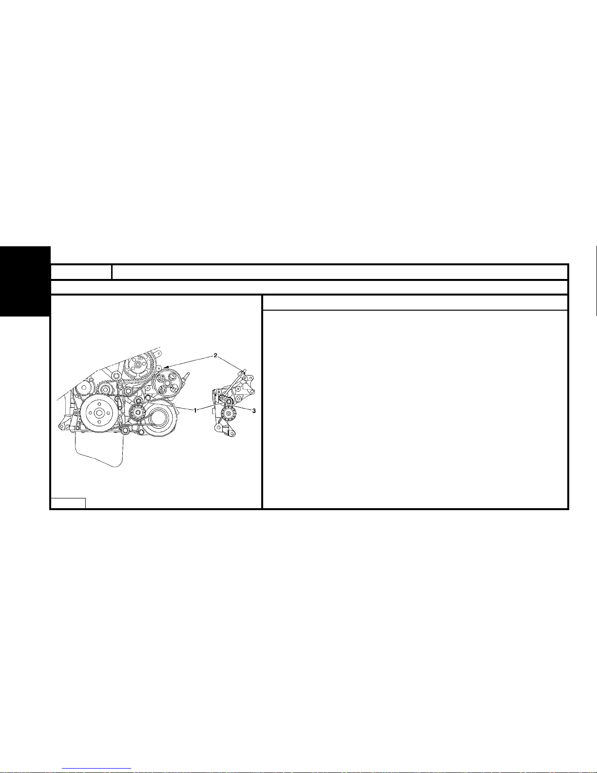
76
ENGINE
XSARA
AUXILIARY EQUIPMENT DRIVE BELT
Power-assisted steering, without air conditioning
Tools :
[1] Belt tension measuring instrument : 4122-T.
Removal.
WARNING : If the belt is to be reused, measure the tension before removal.
- Loosen :
- the screw (1).
- the nut (2).
NOTE : The tensioner arm (3) must be against the alternator.
- Remove the belt.
B1BP1SHD
Engines : WJZ - WJY
Page 80
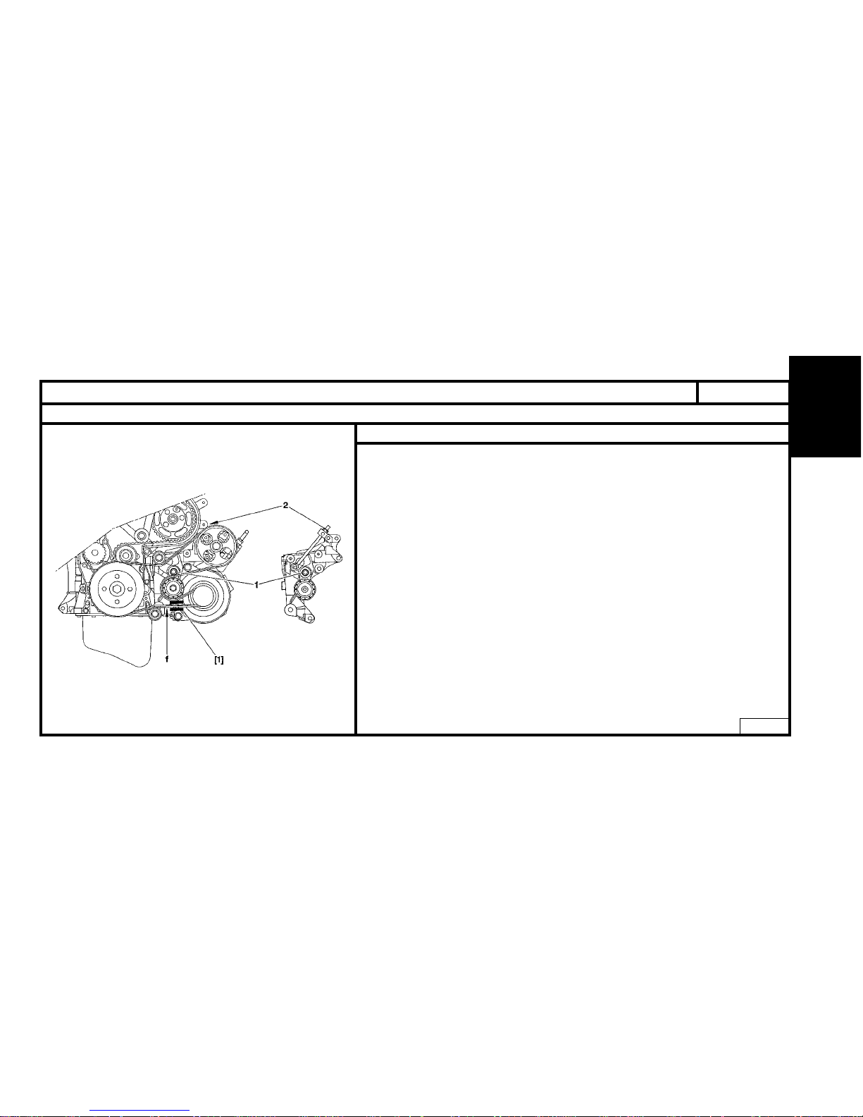
77
ENGINE
AUXILIARY EQUIPMENT DRIVE BELT
Engines : WJZ - WJY
Power-assisted steering, without air conditioning (continued)
XSARA
Refitting.
- Refit the belt.
- Place the tool [1] on belt at "f".
WARNING : Position tool [1], with the knob downwards.
- tighten the nut (2) to obtain a value of :
Reused belt:
Keep the value taken at removal.
New belt:
Tension should be 110 SEEM units.
- Tighten the screw (1) to 9.5 m.daN.
- Check belt tension (tool [1].
Tension should be 144 ± 3 SEEM units.
- Remove the tool [1].
- Start the engine and run it for 10 seconds.
- Stop the engine.
- Place the tool [1] on the belt at "f".
- Tension should be 130 ± 4 SEEM units.
- Remove the tool [1].
B1BP1SJD
Page 81
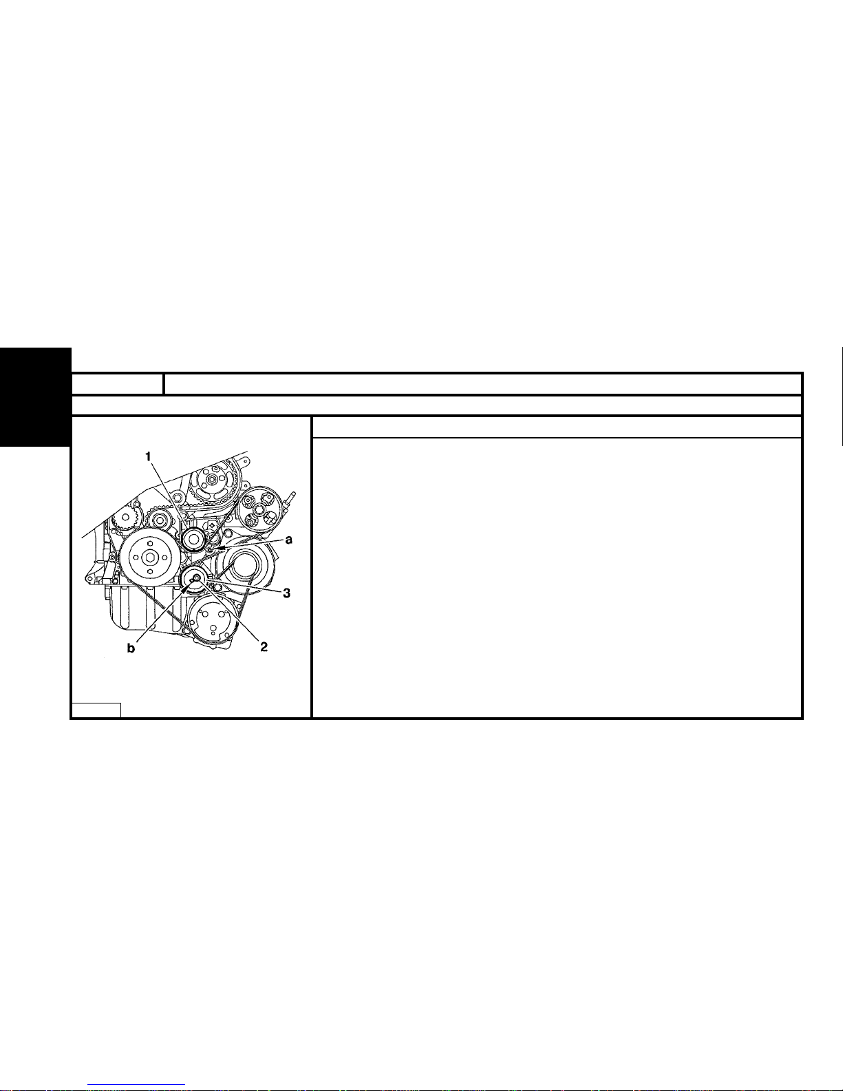
78
ENGINE
XSARA
AUXILIARY EQUIPMENT DRIVE BELT
Power-assisted steering, with air conditioning
Tools :
[1] Dynamic tensioner peg (-) 0188 H.
[2] Belt tension measuring instrument 4122-T.
Removal.
- Peg the dynamic tensioner (1) at "a", using tool [1].
- Loosen the screw (2) of the roller (3).
- Turn the roller (3) backwards.
- Remove the belt.
NOTE : If it can not be pegged at "a" :
- Loosen the screw (2) of the roller (3).
- Using a 7 mm square drive, turn the roller (3) at "b".
- Peg the tensioner (1) at "a", using tool [1].
NOTE : If the belt is broken :
- Support the engine using a jack (insert a wooden block between the housing and the jack).
- Remove the right engine support.
- Using a square drive at (b) turn the tool (3) in the direction of the arrow "a", so that it can be
pegged at "a" using the tool [1].
B1BP1SKC
Engines : WJZ - WJY
Page 82
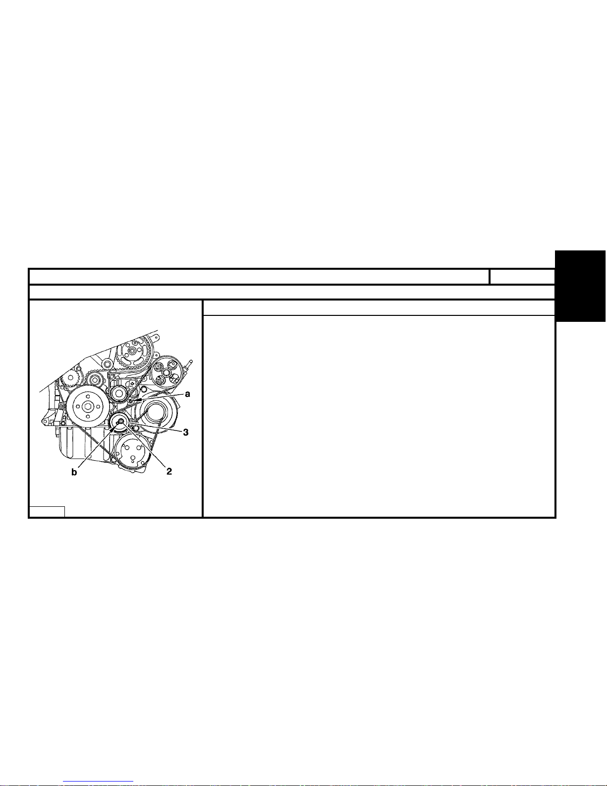
ENGINE
79
AUXILIARY EQUIPMENT DRIVE BELT
Power-assisted steering with air conditioning (continued)
Refitting.
- Refit the belt.
- Using a 7 mm square drive at "b", turn the roller (3), until the tool [1] located at "a" becomes free.
- Tighten the screw (2).
- Remove the tool [1].
B1BP1SLC
Engines : WJZ - WJY
XSARA
Page 83
80
ENGINE
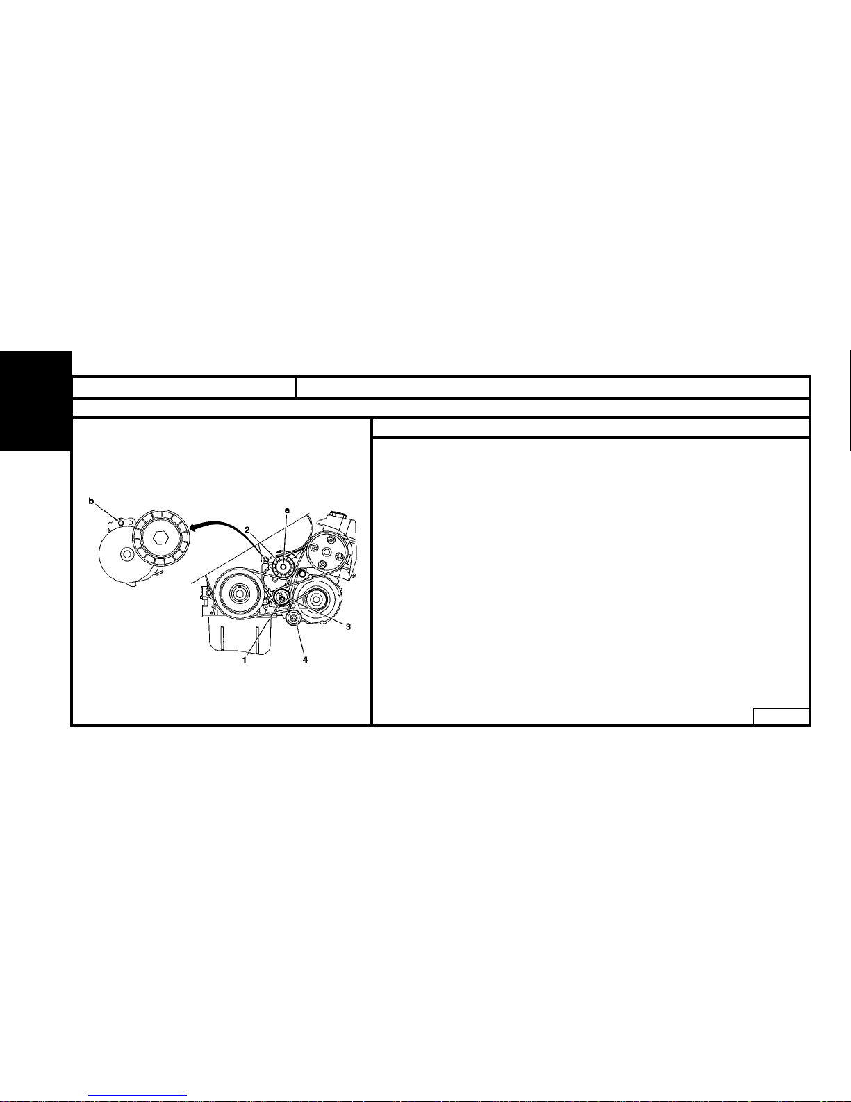
XSARA - XSARA PICASSO AUXILIARY EQUIPMENT DRIVE BELT
Engines : RHY - RHZ
Without air conditioning
B1BP1YKD
Tools
[1] Belt tension adjusting square : (-).0188 J2
[2] Ø 4 mm peg : (-).0188.Q1
[3] Ø 2 mm peg : (-).0188.Q2
[4] Levier de compression tendeur dynamique : (-).0188.Z
Removal
Re-use of belt
WARNING : Mark the direction the belt was fiited in case of re-use of the same belt.
- Compress the tensioner roller (2) by action at « a » (in anti-clockwise direction), tool [4].
- Keep the tensioner roller (2) compressed and remove the belt.
No re-use of belt
- Compress the tensioner roller (2) by action at « a » (in anti-clockwise direction), tool [4].
- Peg using tool [2], at « b ».
- Keep the tensioner roller (2) compressed and remove the belt.
- Loosen the screw (1).
Page 84
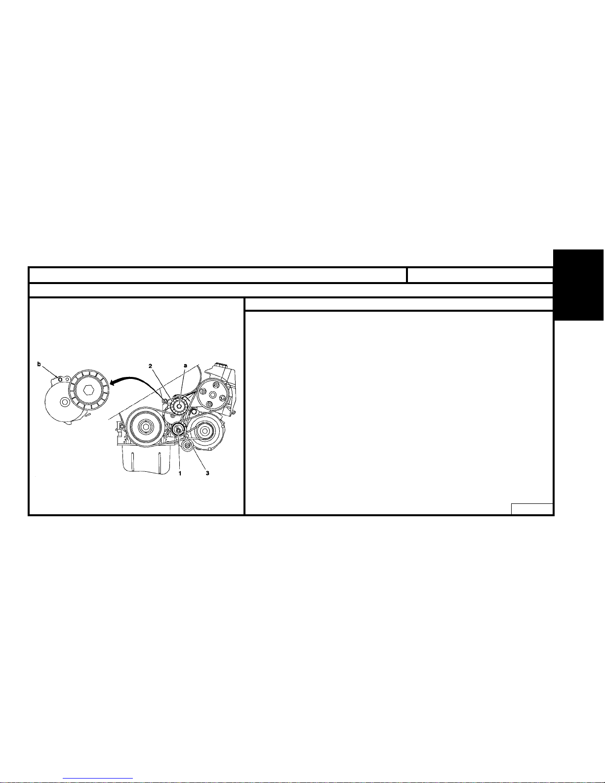
ENGINE
81
XSARA - XSARA PICASSO
AUXILIARY EQUIPMENT DRIVE BELT
Engines : RHY - RHZ
Without air conditioning (continued)
Refitting.
Re-used belt
- Compress the tensioner roller (2) by action at « a » (in anti-clockwise direction), tool [4].
- Refit the belt.
WARNING : Respect the belt-fitting direction.
- Remove the tool [4].
New belt
- Refit the belt.
- Turn the eccentric roller (3), tool [1] (clockwise) to free the tool [2] from its pegging
at « b ».
- Hold the eccentric roller (3), tool [1], and tighten the screw (1) to 4.3 m.daN.
- Remove the tool [2].
- Rotate the crankshaft 4 times in the direction of rotation.
- Check that it is possible to peg at « b », tool [3].
- If not possible to peg, restart the adjustment.
B1BP1YMD
Page 85
82
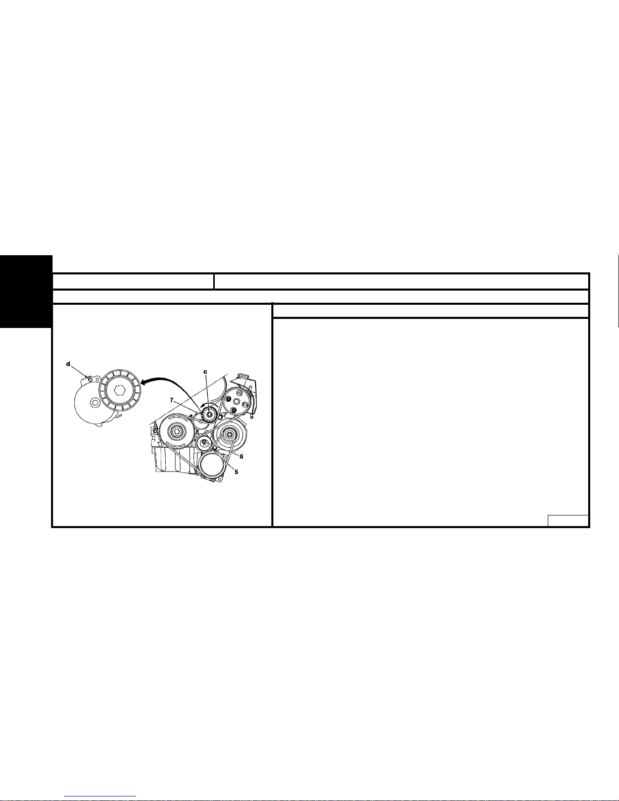
ENGINE
XSARA - XSARA PICASSO
AUXILIARY EQUIPMENT DRIVE BELT
Engines : RHY - RHZ
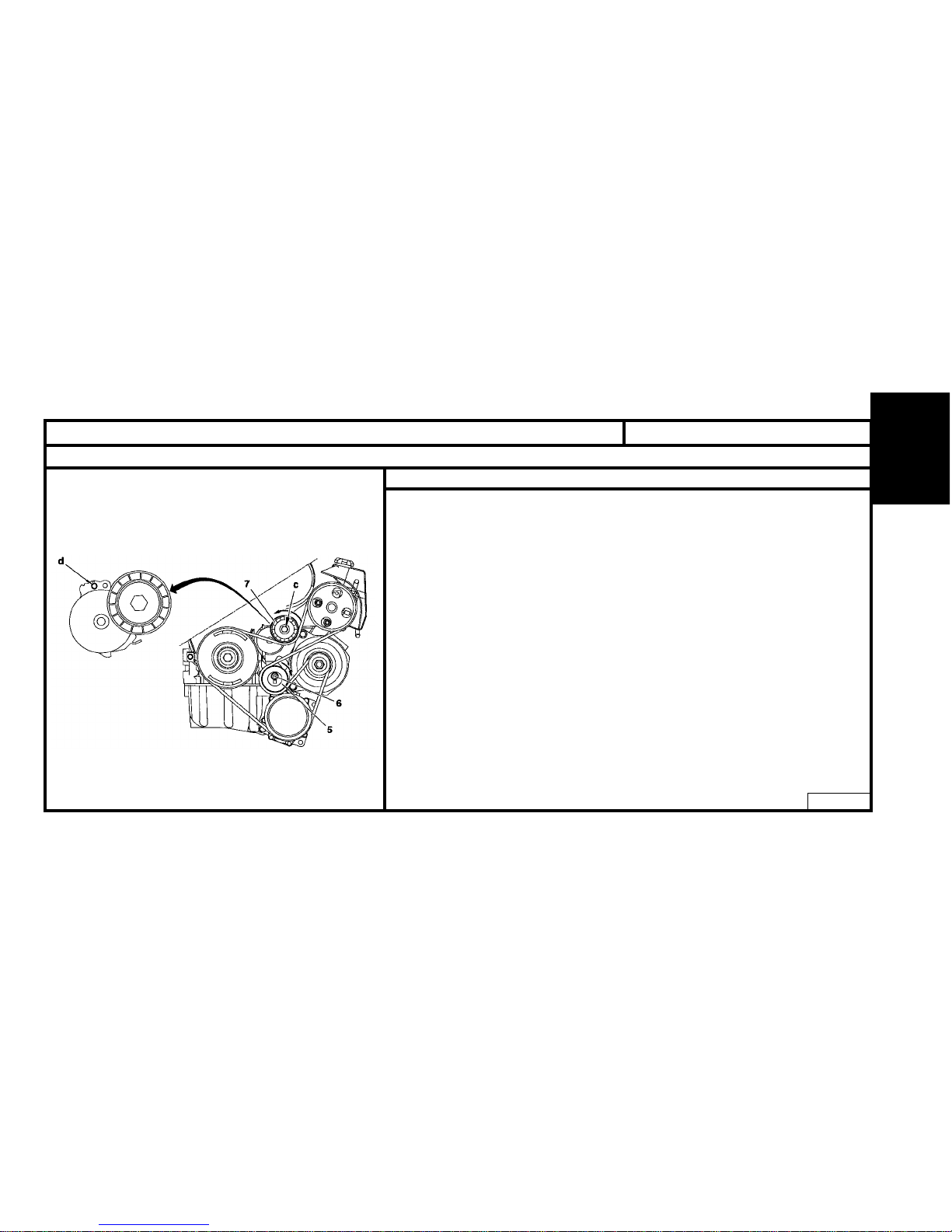
With air conditioning
B1BP1YLD
Tools
[1] Belt tension adjusting square : (-).0188 J2
[2] Ø 4 mm peg : (-).0188.Q1
[3] Ø 2 mm peg : (-).0188.Q2
[4] Dynamic tensioner compression lever : (-).0188.Z
Removal
Re-use of belt
WARNING : Mark the direction the belt was fitted in case of re-use of the same belt.
- Compress the tensioner roller(7) by moving it at « c » (in anti-clockwise direction), tool [4].
- Hold the tensioner roller (7) compressed and remove the belt.
No re-use of belt
- Compress the tensioner roller (7) by moving it at « c » (in anti-clockwise direction),
tool [4].
- Peg using tool [2], at « d ».
- Loosen the screw (6).
- Bring the eccentric roller (5) towards the rear.
- Tighten the screw (6) by hand.
- Remove the belt.
Page 86
ENGINE
83
XSARA - XSARA PICASSO
AUXILIARY EQUIPMENT DRIVE BELT
Engines : RHY - RHZ
With air conditioning (continued)
Refitting.
Re-used belt
- Compress the tensioner roller (7) by action at « c » (in anti-clockwise direction),
tool [4].
- Refit the belt.
WARNING : Respect the direction belt was fitted.
- Remove the tool [4].
New belt
Refit the belt.
- Turn the eccentric roller (5), tool [1] (clockwise) to free the tool [2] from its pegging
at « d ».
- Hold the eccentric roller (5), tool [1], and tighten the screw (6) to 4.3 m.daN.
- Remove the tool [2].
- Rotate the crankshaft 4 times in the direction of rotation.
- Check that it is possible to peg at « d », tool [3].
- If not possible to peg, restart the adjustment.
B1BP1YND
Page 87
84
ENGINE
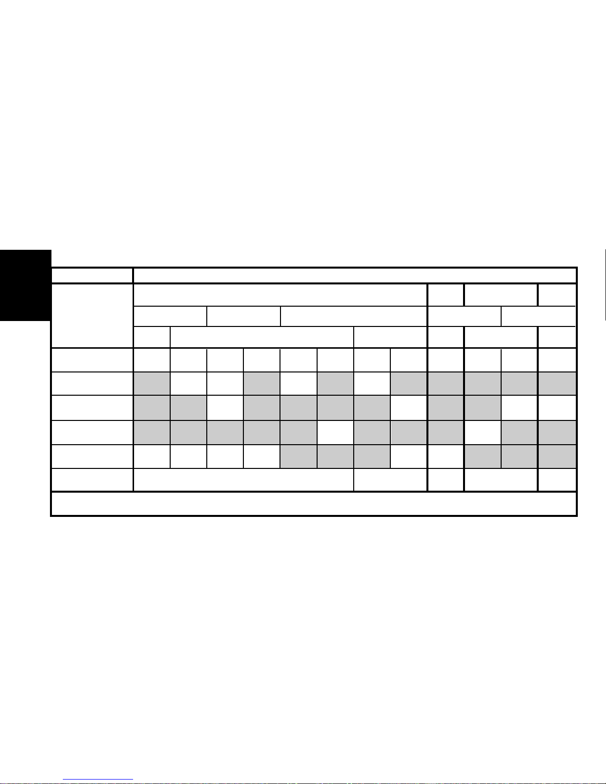
Engine type HDZ HFX KFW KFX NFT NFV NFX NFU LFX 6FZ RFN RFS
SAXO X X X X
XSARA X X X X
XSARA PICASSO X X
BERLINGO X X X X X X
See pages : 96 to 97 103 to 107
CHECKING AND SETTING THE VALVE TIMING (continued)
TU XU
EW
XU
M+
JP
JP4
JB
J4RSJ4
ALL TYPES
13
5710
86 to 88 89 to 92
98 to 102
Page 88
ENGINE
85
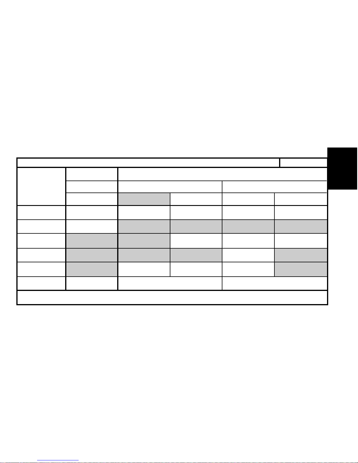
Engine type VJX WJZ WJY RHY RHZ
SAXO X
XSARA X X X
XSARA PICASSO X
BERLINGO X X X
See pages :
CHECKING AND SETTING THE VALVE TIMING (continued)
TU DW
BBTDATED
ALL TYPES
58 10
93 to 95 108 to 112
113 to 117
Page 89
86
ENGINE
TOOLS
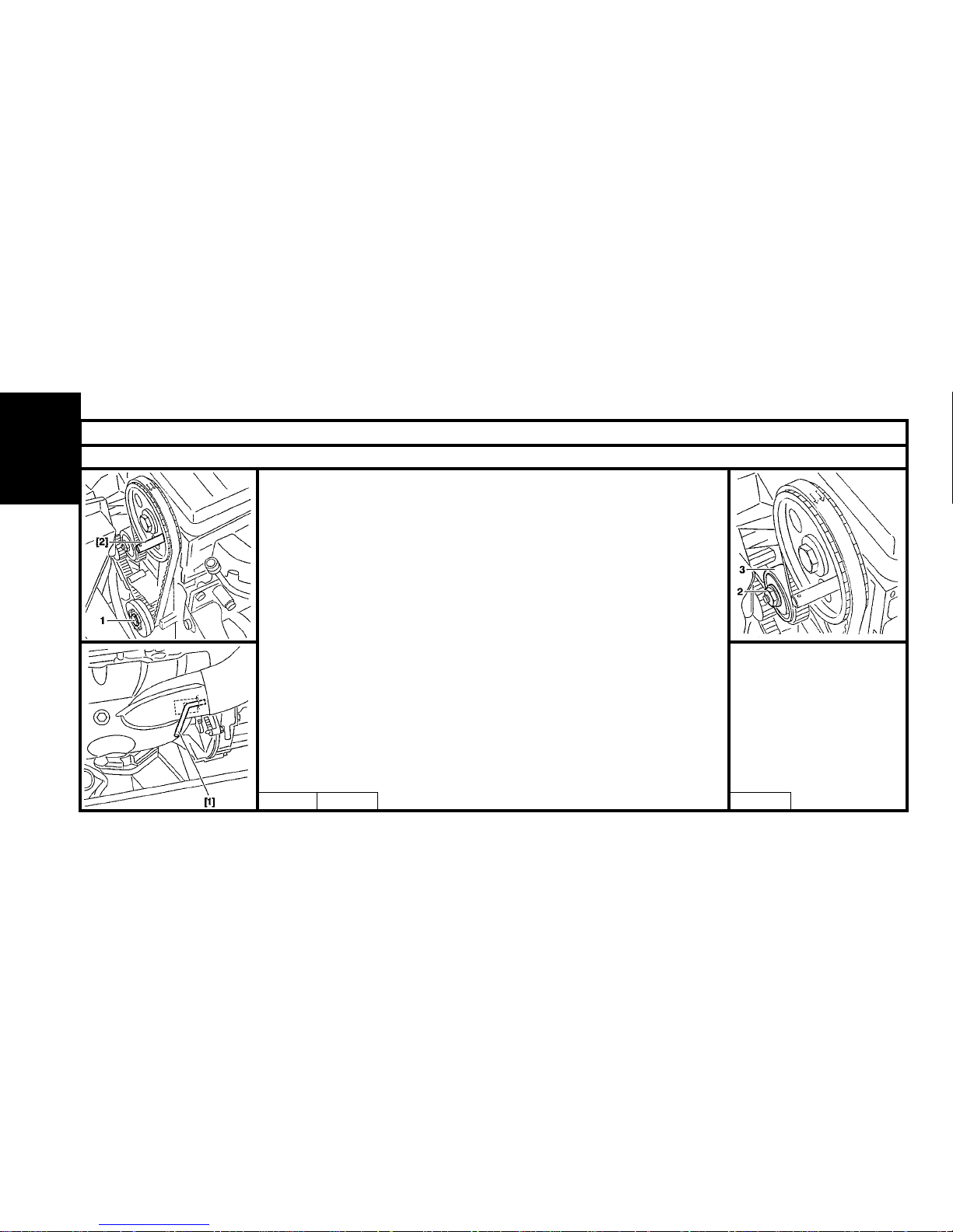
- [1] Flywheel locating peg : 4507-T.A
-
[2] Camshaft pulley locating peg
: 4507-T.B
- [3] Square drive : 4507-T.J
- [4] Belt tension measuring instrument : 4122-T
- [5] Rocker plate : 4533-T.Z
CHECKING THE VALVE TIMING
- Peg the flywheel using the tool [1].
- Peg the camshaft pulley using the tool [2].
SETTING THE VALVE TIMING
NOTE : Remove the spark plugs, to allow the crankshaft to rotate more freely.
- Rotate the engine by the crankshaft screw (1).
- Peg the camshaft gearwheel.
- Peg the flywheel.
- Loosen the nut (2).
- Totally slacken the belt by moving the tensioner roller.
- Remove the belt.
ESSENTIAL : Check that the tensioner roller rotates freely (no stiffness).
CHECKING AND SETTING THE VALVE TIMING
Engines : HDZ - HFX - KFW - KFX - NFT - NFV
Tool kit 4507-T
B1EP067C B1EP066C B1EP0668C
Page 90
ENGINE
87
CHECKING AND SETTING THE VALVE TIMING
Engines : HDZ - HFX - KFW - KFX - NFT - NFV (continued).
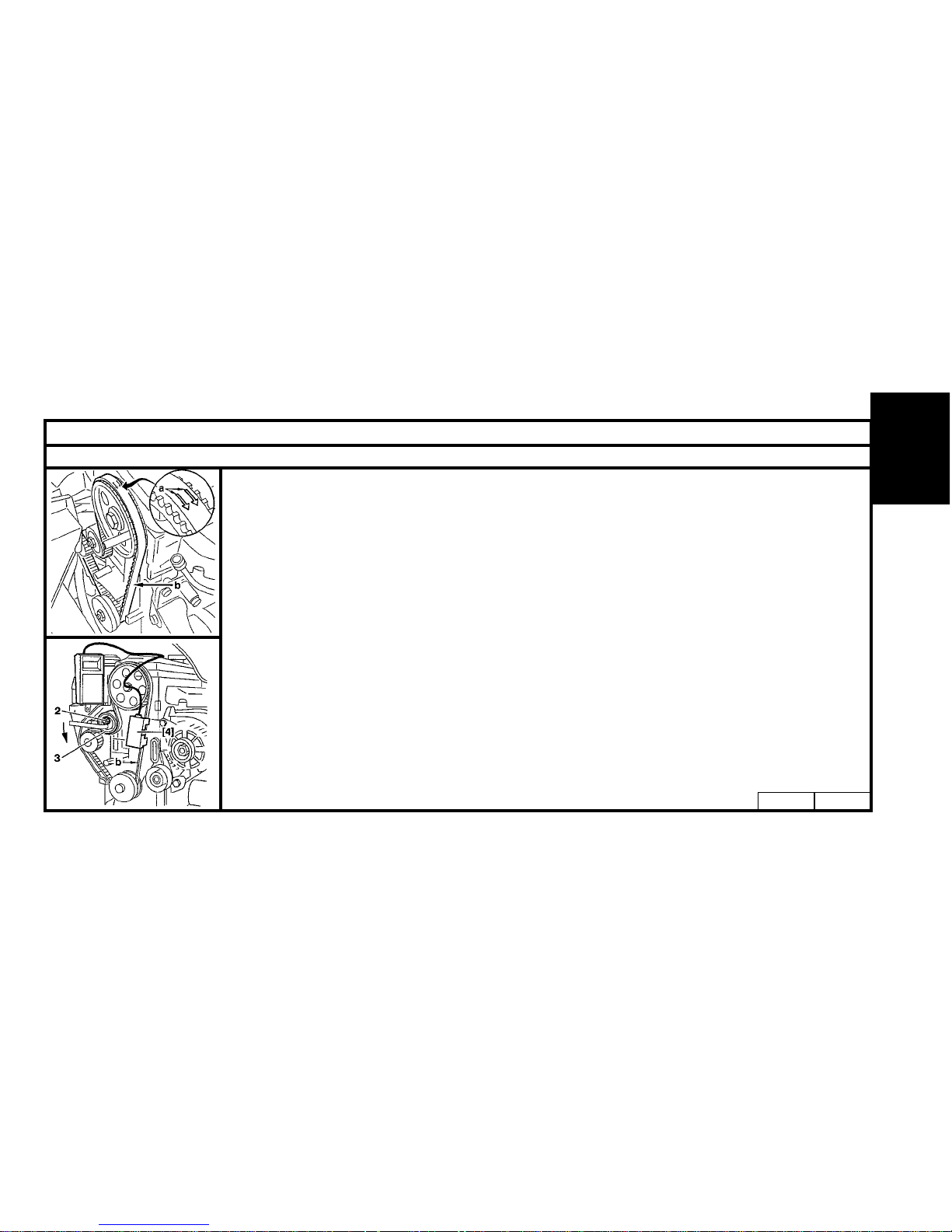
REFITTING THE TIMING BELT
NOTE : Check that the pegs [1] and [2] are in place.
WARNING : Ensure the belt is fitted in the right direction : The arrows «a» signify the crankshaft direction of rotation.
Fit :
- The timing belt, with the belt strip "b" well tightened, in the following order:
Crankshaft pinion, camshaft pulley, water pump pulley, tensioner roller.
- The tool [5] (Ensure it is fitted in the right direction in relation to the timing).
- Bring the tensioner roller into contact with the belt.
- Tighten the nut (2).
PRE-TENSIONING THE TIMING BELT.
- Fit the tool [4] on the tightened belt strip "b".
- Loosen the nut (2).
- Turn the roller (3) in an anti-clockwise direction using a square drive to obtain : 44 SEEM units.
- Tighten the nut (2) to 2 m.daN.
- Remove the tools [1] [2] and [4].
- Rotate the crankshaft by 4 turns in the normal direction.
ESSENTIAL : Never turn the crankshaft backwards.
B1EP06ACB1EP069C
Page 91
88
ENGINE
CHECKING AND SETTING THE VALVE TIMING
Engines : HDZ - HFX - KFW - KFX - NFT - NFV (continued).
PRE-TENSIONING THE TIMING BELT (Cont.)
- Ensure the timing is correctly set by refitting the pegs [1] and [2].
- Remove the cylinder head cover.
- Fit the tool [5] (Ensure it is fitted in the right direction in relation to the timing).
ADJUSTING THE BELT FITTING TENSION
- Fit the tool [4] to the tightened belt strip.
- Loosen the nut (2).
- Slacken the belt (not excessively).
- Tighten the timing belt to obtain : 31 ± 2 SEEM units.
- Tighten the nut (2) to 2.2 m.daN.
- Remove the tools [1] [2] [4] and [5].
CHECKING THE BELT TENSION
- Rotate the crankshaft by 2 turns in the normal direction of rotation.
-Check that the following components can still be pegged :
-Flywheel.
-Camshaft.
ESSENTIAL : If the components cannot be pegged, repeat the belt tensioning procedure.
Page 92
ENGINE
89
CHECKING AND SETTING THE VALVE TIMING
Engines : NFX - NFU
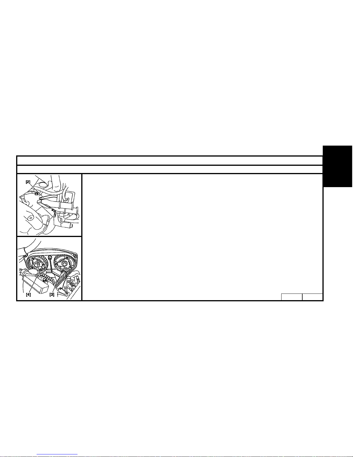
TOOLS
- [1] Belt tension measuring instrument : 4122-T
- [2] Flywheel locating peg : 4507-T.A.
- [3] Camshaft pulley locating peg, exhaust : 4533-T.A. C2
Tool kit 4507-T
- [4] Camshaft pulley locating peg, inlet : 4533-T.A. C
- [5] Tensioning tool : 4707-T.J.
CHECKING THE VALVE TIMING
- Peg the flywheel using the tool [2].
- Peg the exhaust camshaft pulley [3].
- Peg the inlet camshaft pulley [4].
SETTING THE VALVE TIMING
- Peg the flywheel using the tool [2] .
- Peg the camshaft pulleys [3] and [4].
B1EP11CCB1EP11BC
Page 93
90
ENGINE
CHECKING AND SETTING THE VALVE TIMING
Engines : NFX - NFU (continued)
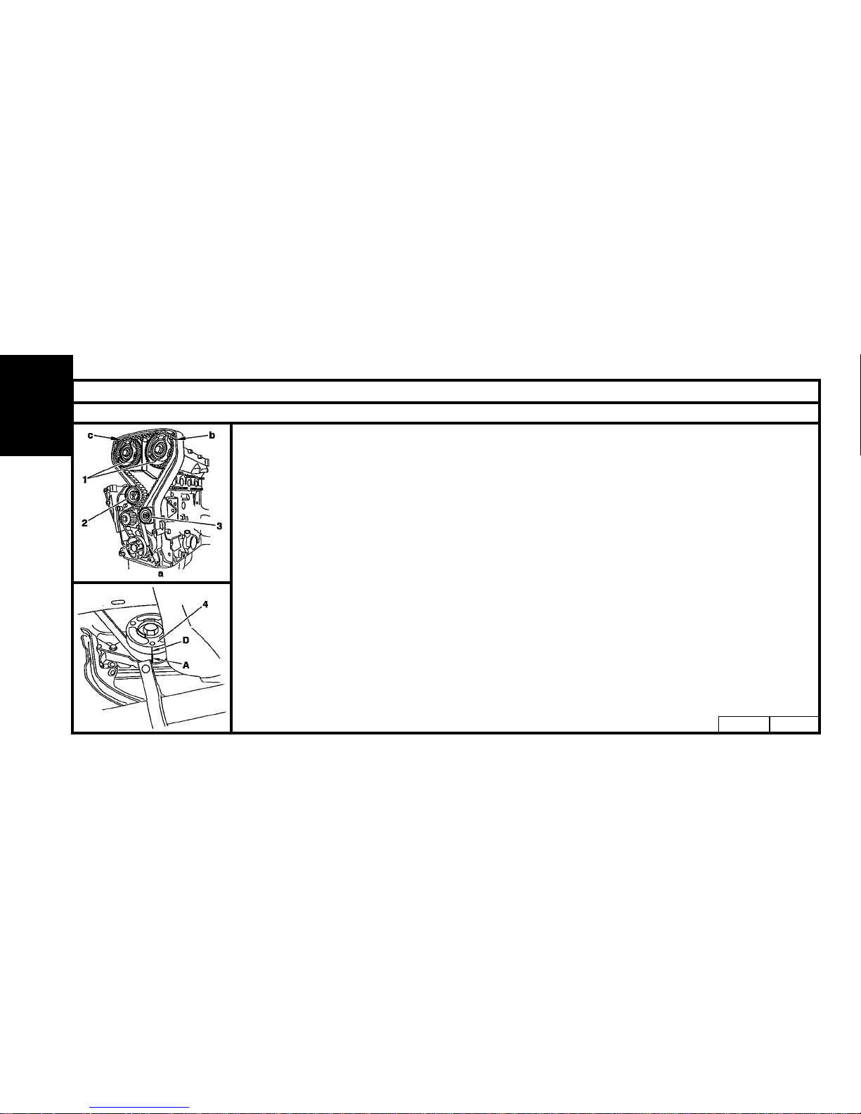
SETTING THE VALVE TIMING
- Loosen the screw (2), remove the belt.
-Loosen the six pulley screws (1) on the hubs.
(There should be a slight amount of friction between the screws and the pinions).
-Check that the rollers (2) and (3) rotate freely.
NOTE : The belt bears three identification marks
*
(a), (b) and (c), facing its own teeth (1), (52) and (72)
respectively.
*
(Identification marks = white paint lines on the back of the belt facing the corresponding teeth).
- Refit the belt.
- Line up mark (A) on the belt with groove (D) of the pinion (4).
- Hold the belt against the pinion (4).
B1EP11ECB1EP11DC
Page 94
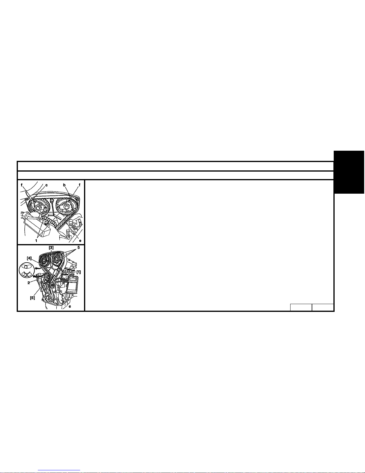
ENGINE
91
CHECKING AND SETTING THE VALVE TIMING
Engines : NFX - NFU (continued)
SETTING THE VALVE TIMING
- Turn the two pulleys (1) clockwise to the end of the slots.
- With the belt strip (e) fully tensioned, place the belt over the pulley, first exhaust side, then inlet side, while
ensuring that marks (b) and (c) on the belt are aligned with marks (f) on the pulleys.
- Hold the belt in this position, and engage it over the water pump pinion and the tensioner roller.
- Fit the tool [1] on the belt strip (e).
- Rotate the roller (2) (using tool [5]) in an anti-clockwise direction, to obtain: 63 SEEM units.
- Tighten the roller (2) to 2 m.daN.
- Tighten the six screws (5) to 1m.daN.
ESSENTIAL : Check that :
- The camshaft pulleys (1) are not at the end of the slots (by removing a screw).
- The markings on the belt are aligned with the markings on the crankshaft and camshaft pulleys.
- If not, repeat the setting procedure.
B1EP11GCB1EP11FC
Page 95
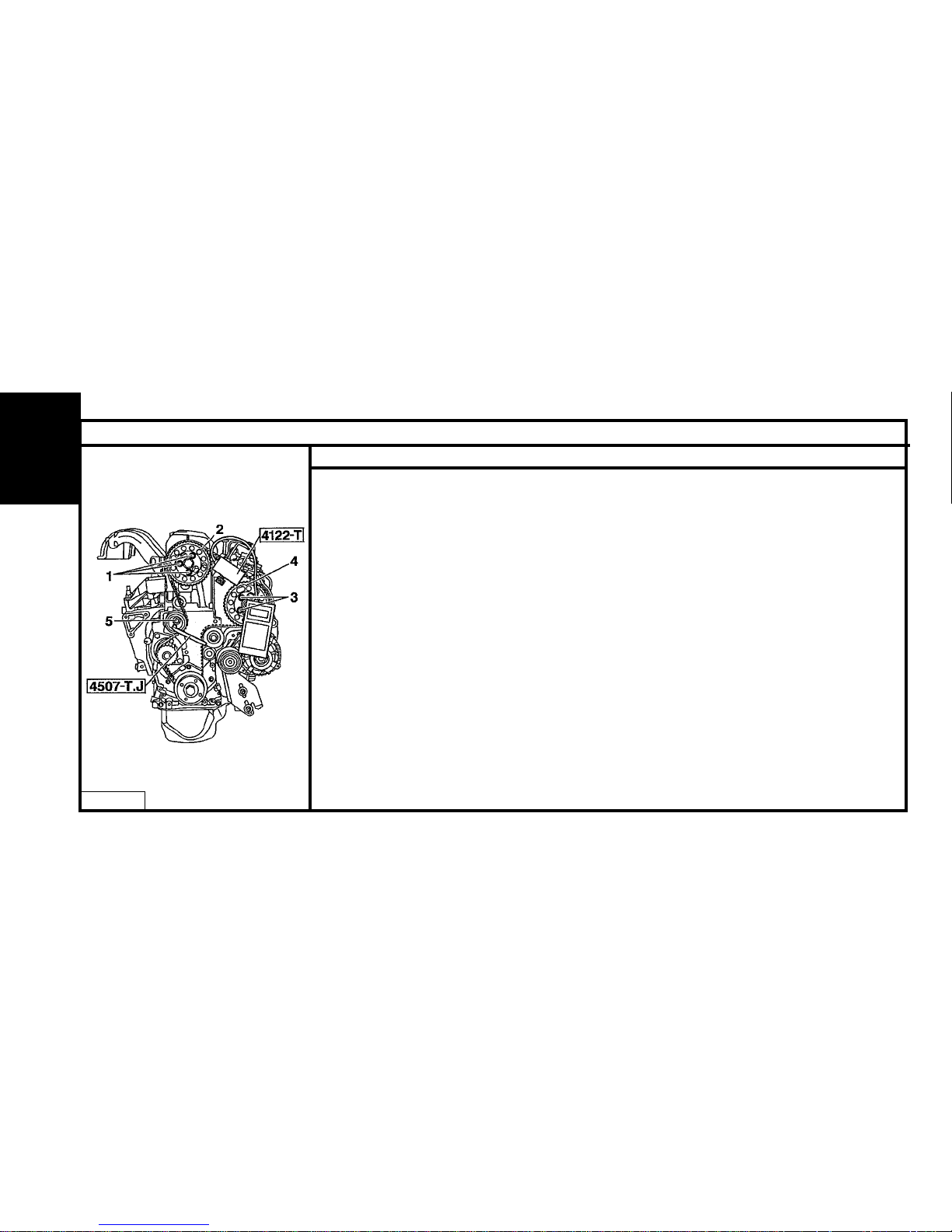
92
ENGINE
CHECKING AND SETTING THE VALVE TIMING
Engines : NFX - NFU (continued)
SETTING THE VALVE TIMING
- Remove the tools [1], [2], [3] and [4].
- Rotate the engine by four turns in the normal direction. (do not turn backwards).
- Peg the flywheel [2].
- Loosen the six screws (5), while ensuring there is still a slight amount of friction with the pulley.
- Peg the camshaft hubs using pegs [3] and [4] .
WARNING : In certain cases, it may be necessary to slightly turn the camshaft using the hub fixing screw.
- Fit the tool [1].
- Loosen the tensioner roller screw (2).
- Rotate the roller (2) (using tool [5]) in an anti-clockwise direction to obtain : 37 SEEM units.
- Tighten the tensioner roller screw (2) to 2 m.daN.
- Tighten the six pulley screws (1) to 1m.daN.
- Remove the tools.
Page 96
ENGINE
93
CHECKING AND SETTING THE VALVE TIMING
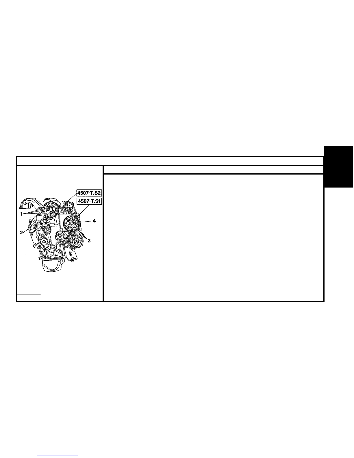
Engine : VJX
TOOLS
- Belt tension measuring instrument : 4099-T or 4122-T
- Flywheel locating peg : 4507-T.A.
- Injection pump pulley locating peg : 4527-T. S1 Tool kit 4507-T
- Camshaft pulley locating peg : 4527-T. S2
- Tensioning lever. : 4507-T.J.
- Pinion locking tool : 6016-T.
CHECKING THE VALVE TIMING
- Peg : the flywheel, the injection pump pulley, the camshaft pulley.
SETTING THE VALVE TIMING
- Peg : the flywheel, the injection pump pulley, the camshaft pulley.
- Loosen the tensioner roller, and remove the belt.
ESSENTIAL: Check that the tensioner and guide rollers rotate freely (no stiffness). If not, replace
the roller(s).
- Loosen the screws (1) and (3) (lock the pulley with tool 6016 - T).
- Position pulleys (2) and (4) to the end of the slots (without tightening the screws (1) and (3)).
B1EP07PC
Page 97
94
ENGINE
CHECKING AND SETTING THE VALVE TIMING
Engine : VJX (continued)
SETTING THE VALVE TIMING
- Fit the belt in the following order :
The crankshaft pinion, the injection pump pulley, the camshaft pulley, the water pump pinion.
WARNING : When positioning the belt on the injection pump and camshaft pulleys, they should
be turned in the opposite direction of rotation so as to engage the nearest tooth.
- Pre-tension (belt strip slightly tightened).
NOTE : Check that the pulley fixings are not at the end of the slots (adjust by one tooth if necessary).
- Tighten the screws (1) and (3) to 0.5 m.daN, loosen by 180°.
(Gently tighten the screws (1) and (3) by hand).
- Loosen the tensioner roller.
- T ension to 100 SEEM units.
- Tighten the tensioner roller to 2.3 m.daN.
B1EP07QC
Page 98
ENGINE
95
CHECKING AND SETTING THE VALVE TIMING
Engine : VJX (continued)
SETTING THE VALVE TIMING
- Tighten the screws (1) and (3) to 2.3 m.daN (lock the pulleys using tool 6016-T).
- Remove the tools.
- Rotate the engine by 10 turns.
- Peg : The flywheel, the pulleys (2) and (4).
NOTE : If necessary, lightly slacken the belt (with the tensioner roller).
- Loosen the screws (1) and (3) by 360° (gently tighten the screws (1) and (3) by hand).
- Set a final tension of 55 ± 5 SEEM units.
- Tighten the tensioner roller, and the screws (1) and (3) to 2.3 m.daN (lock the pulleys using tool 6016-T).
- Remove the tools.
- Rotate the engine by two turns.
NOTE : If the belt is not correctly located on the pinions and pulleys, rotate it by an additional two turns.
- Peg the flywheel.
- Check that the camshaft and injection pump pulleys are correctly pegged.
WARNING : If the visual check is not correct, repeat the setting operation.
- Remove the tools.
Page 99
96
ENGINE
CHECKING AND SETTING THE VALVE TIMING
Engine : LFX
TOOLS
- Belt tension measuring instrument : 4099-T or 4122-T
- Camshaft pulley locating peg : 7004-T.G.
- Crankshaft locating peg : 7014-T.N. Tool kit 7004-T
- Square drive : 7017-T.W.
CHECKING THE VALVE TIMING
- Remove the protective covers.
- Peg the camshaft pulley at "a" using the tool 7004-T.G.
- Peg the crankshaft at "b" using the tool 7014 - T.N.
SETTING THE VALVE TIMING
- Check that the pegs can be engaged correctly at "a" and "b".
- Fit the belt in the following order : camshaft pulley, crankshaft pinion, water pump pinion, tensioner roller.
- Peg the camshaft pulley at "a" and the crankshaft pinion at "b" .
- Remove the peg at "b" only.
- Bring the tensioner roller (2) into contact with the belt.
B1EP07SC
Page 100
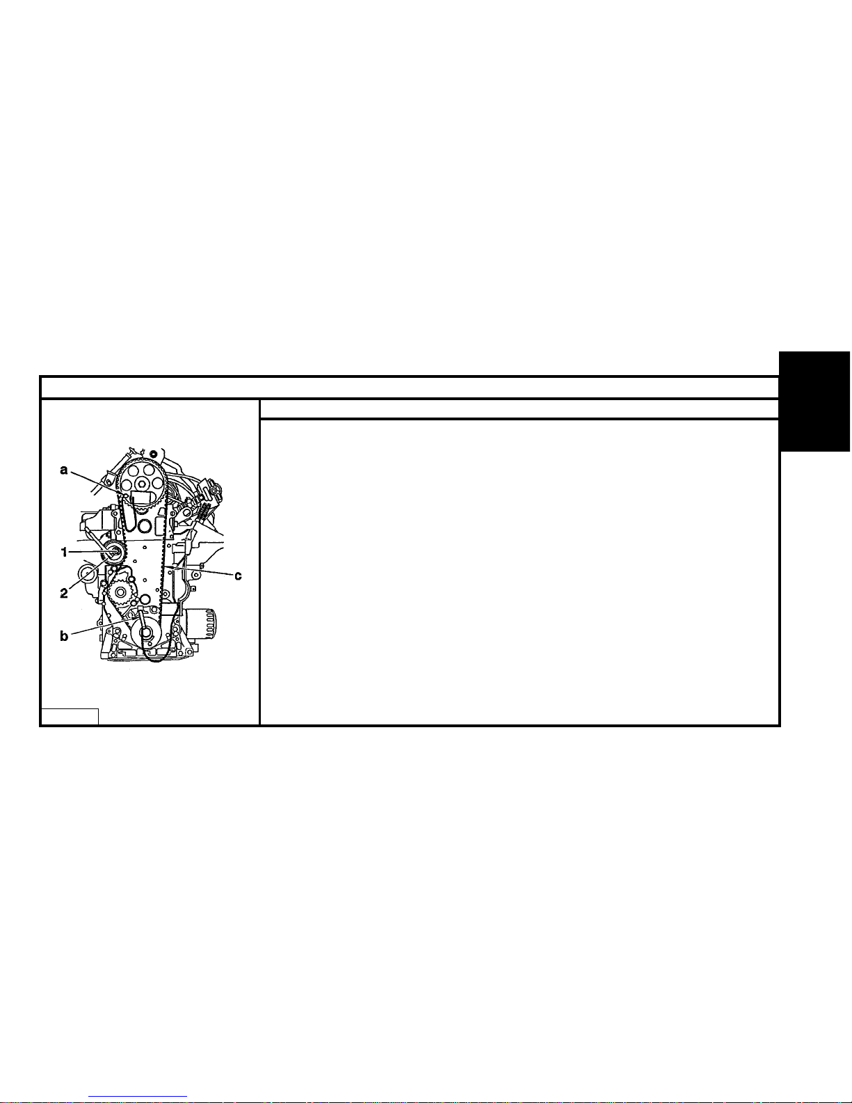
ENGINE
97
CHECKING AND SETTING THE VALVE TIMING
Engine : LFX (continued)
SETTING THE VALVE TIMING
- Fit the tension measuring tool to the middle of the belt strip "c".
- Turn the tensioner roller (2) (anti-clockwise direction) using the tool 7017-T.W to obtain the following
measurement : 30 ± 2 SEEM units.
- Tighten the screw (1) to 2 m.daN.
- Remove the tools.
- Rotate the crankshaft by two turns (do not turn backwards).
- Check the setting by positioning the pegs at "a" and "b".
- Remove the pegs.
CHECKING THE TENSION
- Rotate the crankshaft by two turns (do not turn backwards).
- Peg the camshaft pulley at "a".
- Fit the tension measuring tool on the belt strip at "c".
- The tension measurement should be 44 ± 2 SEEM units.
(If the measurement is not correct, repeat the tensioning procedure).
- Remove the tools.
B1EP07RC
 Loading...