

Page 1

Citrix XenServer ® 5.6 Administrator's Guide
Published June 2010
1.1 Edition
Page 2

Citrix XenServer ® 5.6 Administrator's Guide
Copyright © 2009 Citrix All Rights Reserved.
Version: 5.6
Citrix, Inc.
851 West Cypress Creek Road
Fort Lauderdale, FL 33309
United States of America
Disclaimers
This document is furnished "AS IS." Citrix, Inc. disclaims all warranties regarding the contents of this
document, including, but not limited to, implied warranties of merchantability and fitness for any particular
purpose. This document may contain technical or other inaccuracies or typographical errors. Citrix, Inc.
reserves the right to revise the information in this document at any time without notice. This document and
the software described in this document constitute confidential information of Citrix, Inc. and its licensors,
and are furnished under a license from Citrix, Inc.
Citrix Systems, Inc., the Citrix logo, Citrix XenServer and Citrix XenCenter, are trademarks of Citrix Systems,
Inc. in the United States and other countries. All other products or services mentioned in this document are
trademarks or registered trademarks of their respective companies.
Trademarks
Citrix ®
XenServer ®
XenCenter ®
1.1 Edition
Page 3

Table of Contents
Document Overview .................................................................................... 1
How this Guide relates to other documentation .................................................................................. 1
Managing users ............................................................................................ 2
Authenticating users using Active Directory (AD) ................................................................................. 2
Configuring Active Directory authentication ................................................................................ 3
User authentication .............................................................................................................. 5
Removing access for a user .................................................................................................. 6
Leaving an AD domain ......................................................................................................... 6
Role Based Access Control ........................................................................................................... 7
Roles ................................................................................................................................ 8
Definitions of RBAC roles and permissions ................................................................................ 9
Working with RBAC using the xe CLI ..................................................................................... 14
To list all the available defined roles in XenServer ............................................................... 14
To display a list of current subjects: ............................................................................... 15
To add a subject to RBAC ........................................................................................... 16
To assign an RBAC role to a created subject ................................................................... 16
To change a subject’s RBAC role: ................................................................................. 17
Auditing ........................................................................................................................... 17
Audit log xe CLI commands ......................................................................................... 17
To obtain all audit records from the pool ......................................................................... 17
To obtain audit records of the pool since a precise millisecond timestamp ............................... 17
To obtain audit records of the pool since a precise minute timestamp ..................................... 17
How does XenServer compute the roles for the session? ............................................................ 18
XenServer hosts and resource pools ....................................................... 19
Hosts and resource pools overview ................................................................................................ 19
Requirements for creating resource pools ........................................................................................ 19
iii
Page 4

Creating a resource pool ............................................................................................................. 20
Creating heterogeneous resource pools .......................................................................................... 21
Adding shared storage ................................................................................................................ 21
Removing a XenServer host from a resource pool ............................................................................. 22
High Availability .......................................................................................................................... 23
HA Overview ..................................................................................................................... 23
Overcommitting ......................................................................................................... 23
Overcommitment Warning ............................................................................................ 23
Host Fencing ............................................................................................................ 23
Configuration Requirements .................................................................................................. 24
Restart priorities ................................................................................................................ 24
Enabling HA on a XenServer pool .................................................................................................. 25
Enabling HA using the CLI ................................................................................................... 25
Removing HA protection from a VM using the CLI ..................................................................... 26
Recovering an unreachable host ........................................................................................... 26
Shutting down a host when HA is enabled .............................................................................. 26
Shutting down a VM when it is protected by HA ....................................................................... 26
Host Power On ......................................................................................................................... 27
Powering on hosts remotely ................................................................................................. 27
Using the CLI to Manage Host Power On ............................................................................... 27
To enable Host Power On using the CLI ......................................................................... 28
To turn on hosts remotely using the CLI .......................................................................... 28
Configuring a Custom Script for XenServer’s Host Power On Feature ............................................. 28
Key/Value Pairs ......................................................................................................... 28
host.power_on_mode .......................................................................................... 28
host.power_on_config ......................................................................................... 29
Sample Script ........................................................................................................... 29
Storage ........................................................................................................ 30
iv
Page 5

Storage Overview ....................................................................................................................... 30
Storage Repositories (SRs) ................................................................................................... 30
Virtual Disk Images (VDIs) .................................................................................................... 30
Physical Block Devices (PBDs) .............................................................................................. 30
Virtual Block Devices (VBDs) ................................................................................................ 31
Summary of Storage objects ................................................................................................ 31
Virtual Disk Data Formats .................................................................................................... 31
VHD-based VDIs ........................................................................................................ 32
VHD Chain Coalescing ........................................................................................ 32
Space Utilization ................................................................................................ 32
LUN-based VDIs ........................................................................................................ 33
Storage configuration .................................................................................................................. 33
Creating Storage Repositories ............................................................................................... 33
Upgrading LVM storage from XenServer 5.0 or earlier ................................................................. 34
LVM performance considerations ........................................................................................... 34
VDI types ................................................................................................................. 34
Creating a raw virtual disk using the xe CLI ..................................................................... 34
Converting between VDI formats ........................................................................................... 35
Probing an SR .................................................................................................................. 35
Storage Multipathing ........................................................................................................... 38
Storage Repository Types ............................................................................................................ 39
Local LVM ........................................................................................................................ 40
Creating a local LVM SR (lvm) ....................................................................................... 40
Local EXT3 VHD ................................................................................................................ 40
Creating a local EXT3 SR (ext) ...................................................................................... 40
udev ............................................................................................................................... 41
ISO ................................................................................................................................. 41
EqualLogic ....................................................................................................................... 41
v
Page 6

Creating a shared EqualLogic SR .................................................................................. 41
EqualLogic VDI Snapshot space allocation with XenServer EqualLogic Adapter ......................... 42
Creating a VDI using the CLI ................................................................................ 43
NetApp ............................................................................................................................ 43
Creating a shared NetApp SR over iSCSI ........................................................................ 46
Managing VDIs in a NetApp SR ................................................................................... 47
Taking VDI snapshots with a NetApp SR ......................................................................... 47
Software iSCSI Support ....................................................................................................... 47
XenServer Host iSCSI configuration ............................................................................... 48
Managing Hardware Host Bus Adapters (HBAs) ........................................................................ 48
Sample QLogic iSCSI HBA setup ................................................................................. 48
Removing HBA-based SAS, FC or iSCSI device entries ..................................................... 49
LVM over iSCSI ................................................................................................................. 49
Creating a shared LVM over iSCSI SR using the software iSCSI initiator (lvmoiscsi) .................... 49
Creating a shared LVM over Fibre Channel / iSCSI HBA or SAS SR (lvmohba) .......................... 50
NFS VHD ......................................................................................................................... 52
Creating a shared NFS SR (nfs) ................................................................................... 53
LVM over hardware HBA ..................................................................................................... 53
Citrix StorageLink Gateway (CSLG) SRs .................................................................................. 54
Creating a shared StorageLink SR ................................................................................. 54
Managing Storage Repositories .................................................................................................... 58
Destroying or forgetting a SR ............................................................................................... 59
Introducing an SR ............................................................................................................. 59
Resizing an SR .................................................................................................................. 60
Converting local Fibre Channel SRs to shared SRs .................................................................... 60
Moving Virtual Disk Images (VDIs) between SRs ........................................................................ 60
Copying all of a VM’s VDIs to a different SR .................................................................... 60
Copying individual VDIs to a different SR ......................................................................... 60
vi
Page 7

Adjusting the disk IO scheduler ............................................................................................. 61
Virtual disk QoS settings ............................................................................................................. 61
Configuring VM memory ........................................................................... 63
What is Dynamic Memory Control (DMC)? ....................................................................................... 63
The concept of dynamic range ............................................................................................. 63
The concept of static range ................................................................................................. 64
DMC Behaviour ................................................................................................................. 64
How does DMC Work? ....................................................................................................... 64
Memory constraints ............................................................................................................ 65
Supported operating systems ............................................................................................... 65
xe CLI commands ..................................................................................................................... 66
Display the static memory properties of a VM ........................................................................... 66
Display the dynamic memory properties of a VM ....................................................................... 66
Updating memory properties ................................................................................................ 67
Update individual memory properties ...................................................................................... 68
Upgrade issues ......................................................................................................................... 68
Workload Balancing interaction ..................................................................................................... 68
Networking .................................................................................................. 69
XenServer networking overview ..................................................................................................... 69
Network objects ................................................................................................................ 70
Networks ......................................................................................................................... 70
VLANs ............................................................................................................................. 70
Using VLANs with host management interfaces ................................................................ 70
Using VLANs with virtual machines ................................................................................ 70
Using VLANs with dedicated storage NICs ...................................................................... 71
Combining management interfaces and guest VLANs on a single host NIC .............................. 71
NIC bonds ....................................................................................................................... 71
vii
Page 8

Initial networking configuration ............................................................................................. 72
Managing networking configuration ................................................................................................ 72
Creating networks in a standalone server ................................................................................ 72
Creating networks in resource pools ...................................................................................... 73
Creating VLANs ................................................................................................................. 73
Creating NIC bonds on a standalone host ............................................................................... 74
Creating a NIC bond on a dual-NIC host ......................................................................... 74
Controlling the MAC address of the bond ........................................................................ 75
Reverting NIC bonds .................................................................................................. 75
Creating NIC bonds in resource pools .................................................................................... 75
Adding NIC bonds to new resource pools ....................................................................... 76
Adding NIC bonds to an existing pool ............................................................................ 77
Configuring a dedicated storage NIC ...................................................................................... 79
Controlling Quality of Service (QoS) ........................................................................................ 79
Changing networking configuration options .............................................................................. 79
Hostname ................................................................................................................ 80
DNS servers ............................................................................................................. 80
Changing IP address configuration for a standalone host .................................................... 80
Changing IP address configuration in resource pools .......................................................... 80
Management interface ................................................................................................. 81
Disabling management access ...................................................................................... 81
Adding a new physical NIC .......................................................................................... 82
NIC/PIF ordering in resource pools ........................................................................................ 82
Verifying NIC ordering ................................................................................................. 82
Re-ordering NICs ....................................................................................................... 82
Networking Troubleshooting ......................................................................................................... 83
Diagnosing network corruption .............................................................................................. 83
Recovering from a bad network configuration ........................................................................... 84
viii
Page 9

Workload Balancing ................................................................................. 85
What’s New? ............................................................................................................................ 85
New Features .................................................................................................................... 85
Changes .......................................................................................................................... 86
Workload Balancing Overview ....................................................................................................... 86
Workload Balancing Basic Concepts ...................................................................................... 87
Workload Balancing Installation Overview ........................................................................................ 87
Workload Balancing System Requirements .............................................................................. 88
Supported XenServer Versions ...................................................................................... 88
Supported Operating Systems ...................................................................................... 88
Recommended Hardware ............................................................................................ 88
Workload Balancing Data Store Requirements .......................................................................... 89
SQL Server Database Authentication Requirements .......................................................... 89
Operating System Language Support ..................................................................................... 90
Preinstallation Considerations ................................................................................................ 90
WLB Access Control Permissions .................................................................................. 91
Installing Workload Balancing ................................................................................................ 91
To install Workload Balancing server ............................................................................... 92
To verify your Workload Balancing installation ................................................................... 93
Configuring Firewalls ........................................................................................................... 94
Upgrading Workload Balancing ............................................................................................. 94
Upgrading Workload Balancing on the Same Operating System ............................................ 95
Upgrading SQL Server ................................................................................................ 95
Upgrading Workload Balancing and the Operating System .................................................. 95
Initializing Workload Balancing ...................................................................................................... 95
To initialize Workload Balancing ............................................................................................. 96
Authorization for Workload Balancing .................................................................................... 97
Configuring Antivirus Software ............................................................................................... 98
ix
Page 10

Configuring Workload Balancing Settings ........................................................................................ 98
To display the Workload Balancing Configuration dialog box ........................................................ 99
Adjusting the Optimization Mode ........................................................................................... 99
Fixed ....................................................................................................................... 99
Scheduled ................................................................................................................ 99
To set an optimization mode for all time periods .............................................................. 100
To specify times when the optimization mode will change automatically ................................. 100
To edit or delete an automatic optimization interval ........................................................... 100
Optimizing and Managing Power Automatically ...................................................................... 100
Accepting Optimization Recommendations Automatically ................................................... 101
Enabling Workload Balancing Power Management ........................................................... 101
Designing Environments for Power Management and VM Consolidation ................................ 102
To apply optimization recommendations automatically ....................................................... 103
To select servers for power management ....................................................................... 103
Changing the Critical Thresholds .......................................................................................... 103
Default Settings for Critical Thresholds .......................................................................... 104
To change the critical thresholds .................................................................................. 104
Tuning Metric Weightings ................................................................................................... 104
To edit metric weighting factors ................................................................................... 105
Excluding Hosts from Recommendations ............................................................................... 105
To exclude hosts from placement and optimization recommendations ................................... 105
Configuring Optimization Intervals, Report Subscriptions, and Data Storage ................................... 106
Historical Data (Storage Time) ..................................................................................... 106
To configure the data storage period .................................................................... 106
VM Optimization Criteria ............................................................................................ 106
Length of Time Between Optimization Recommendations After VM Moves ..................... 106
Number of Times an Optimization Recommendation is Made ...................................... 107
Setting the Minimum Optimization Severity ............................................................. 107
x
Page 11

Modifying the Aggressiveness Setting ................................................................... 107
Receiving Reports by Email Automatically (Report Subscriptions) ......................................... 108
To configure report subscriptions ........................................................................ 109
Choosing an Optimal Server for VM Initial Placement, Migrate, and Resume ........................................... 109
To start a virtual machine on the optimal server ....................................................................... 109
To resume a virtual machine on the optimal server ........................................................... 109
Accepting Optimization Recommendations ..................................................................................... 110
To accept an optimization recommendation ............................................................................ 110
Administering Workload Balancing ................................................................................................ 110
Disabling Workload Balancing ............................................................................................ 111
Reconfiguring a Pool to Use Another WLB Server .................................................................... 111
Updating Workload Balancing Credentials .............................................................................. 112
Uninstalling Workload Balancing ......................................................................................... 113
Customizing Workload Balancing ......................................................................................... 113
Entering Maintenance Mode with Workload Balancing Enabled ........................................................... 113
To enter maintenance mode with Workload Balancing enabled .................................................... 114
Working with Workload Balancing Reports ..................................................................................... 114
Introduction ..................................................................................................................... 114
Subscribing to Workload Balancing Reports ........................................................................... 114
Using Workload Balancing Reports for Tasks .......................................................................... 115
Evaluating the Effectiveness of Your Optimization Thresholds .............................................. 115
Generating and Managing Workload Balancing Reports ............................................................ 115
To generate a Workload Balancing report ....................................................................... 115
To subscribe to a Workload Balancing report .................................................................. 115
To cancel a report subscription ................................................................................... 116
To navigate in a Workload Balancing Report ................................................................... 116
To print a Workload Balancing report ............................................................................ 117
To export a Workload Balancing report .................................................................. 117
xi
Page 12

Displaying Workload Balancing Reports ................................................................................. 117
Report Generation Features ........................................................................................ 117
Toolbar Buttons ....................................................................................................... 117
Workload Balancing Report Glossary .................................................................................... 118
Host Health History .................................................................................................. 118
Pool Optimization Performance History .......................................................................... 119
Pool Audit Log History .............................................................................................. 119
Audit Log Event Names ..................................................................................... 120
Pool Health ............................................................................................................. 120
Pool Health History ................................................................................................... 121
Pool Optimization History ........................................................................................... 121
Virtual Machine Motion History .................................................................................... 122
Virtual Machine Performance History ............................................................................. 122
Backup and recovery ............................................................................... 123
Backups ................................................................................................................................. 123
Full metadata backup and disaster recovery (DR) ............................................................................ 124
DR and metadata backup overview ...................................................................................... 124
Backup and restore using xsconsole .................................................................................... 124
Moving SRs between hosts and Pools .................................................................................. 125
Using Portable SRs for Manual Multi-Site Disaster Recovery ...................................................... 126
VM Snapshots ......................................................................................................................... 126
Regular Snapshots ........................................................................................................... 127
Quiesced Snapshots ......................................................................................................... 127
Snapshots with memory .................................................................................................... 127
Creating a VM Snapshot .................................................................................................... 127
Creating a snapshot with memory ........................................................................................ 128
To list all of the snapshots on a XenServer pool ...................................................................... 128
To list the snapshots on a particular VM ................................................................................ 128
xii
Page 13

Restoring a VM to its previous state ..................................................................................... 129
Deleting a snapshot .................................................................................................. 129
Snapshot Templates ........................................................................................................ 130
Creating a template from a snapshot ............................................................................ 130
Exporting a snapshot to a template .............................................................................. 131
Advanced Notes for Quiesced Snapshots ...................................................................... 131
Coping with machine failures ...................................................................................................... 133
Member failures ............................................................................................................... 133
Master failures ................................................................................................................. 133
Pool failures .................................................................................................................... 134
Coping with Failure due to Configuration Errors ....................................................................... 134
Physical Machine failure ..................................................................................................... 134
Monitoring and managing XenServer .................................................... 136
Alerts ..................................................................................................................................... 136
Customizing Alerts ............................................................................................................ 137
Configuring Email Alerts ..................................................................................................... 138
Custom Fields and Tags ............................................................................................................ 139
Custom Searches ..................................................................................................................... 139
Determining throughput of physical bus adapters ............................................................................ 139
Troubleshooting ........................................................................................ 140
XenServer host logs .................................................................................................................. 140
Sending host log messages to a central server ....................................................................... 140
XenCenter logs ........................................................................................................................ 141
Troubleshooting connections between XenCenter and the XenServer host ............................................. 141
A. Command line interface ..................................................................... 142
Basic xe syntax ....................................................................................................................... 142
Special characters and syntax ..................................................................................................... 143
xiii
Page 14

Command types ...................................................................................................................... 144
Parameter types ............................................................................................................... 145
Low-level param commands ............................................................................................... 145
Low-level list commands .................................................................................................... 146
xe command reference .............................................................................................................. 147
Bonding commands .......................................................................................................... 147
bond-create ............................................................................................................ 147
bond-destroy ........................................................................................................... 147
CD commands ................................................................................................................ 148
cd-list .................................................................................................................... 149
Console commands .......................................................................................................... 149
Event commands ............................................................................................................. 150
event-wait ............................................................................................................... 150
Host (XenServer host) commands ........................................................................................ 151
host-backup ............................................................................................................ 154
host-bugreport-upload ............................................................................................... 155
host-crashdump-destroy ............................................................................................ 155
host-crashdump-upload ............................................................................................. 155
host-disable ............................................................................................................ 155
host-dmesg ............................................................................................................ 155
host-emergency-management-reconfigure ...................................................................... 155
host-enable ............................................................................................................. 156
host-evacuate .......................................................................................................... 156
host-forget .............................................................................................................. 156
host-get-system-status .............................................................................................. 156
host-get-system-status-capabilities ............................................................................... 157
host-is-in-emergency-mode ........................................................................................ 158
host-apply-edition .................................................................................................... 158
xiv
Page 15

license-server-address ............................................................................................... 158
license-server-port .................................................................................................... 158
host-license-add ...................................................................................................... 158
host-license-view ...................................................................................................... 159
host-logs-download .................................................................................................. 159
host-management-disable .......................................................................................... 159
host-management-reconfigure ..................................................................................... 159
host-power-on ......................................................................................................... 160
host-set-power-on .................................................................................................... 160
host-reboot ............................................................................................................. 160
host-restore ............................................................................................................ 160
host-set-hostname-live .............................................................................................. 160
host-shutdown ......................................................................................................... 161
host-syslog-reconfigure .............................................................................................. 161
Log commands ............................................................................................................... 161
log-get-keys ............................................................................................................ 161
log-reopen .............................................................................................................. 161
log-set-output .......................................................................................................... 161
Message commands ......................................................................................................... 162
message-create ....................................................................................................... 162
message-list ............................................................................................................ 162
Network commands .......................................................................................................... 163
network-create ......................................................................................................... 164
network-destroy ....................................................................................................... 164
Patch (update) commands ................................................................................................. 164
patch-apply ............................................................................................................. 165
patch-clean ............................................................................................................. 165
patch-pool-apply ...................................................................................................... 165
xv
Page 16

patch-precheck ........................................................................................................ 165
patch-upload ........................................................................................................... 165
PBD commands .............................................................................................................. 165
pbd-create .............................................................................................................. 166
pbd-destroy ............................................................................................................ 166
pbd-plug ................................................................................................................ 166
pbd-unplug ............................................................................................................. 166
PIF commands ................................................................................................................ 166
pif-forget ................................................................................................................ 169
pif-introduce ............................................................................................................ 169
pif-plug .................................................................................................................. 170
pif-reconfigure-ip ...................................................................................................... 170
pif-scan .................................................................................................................. 170
pif-unplug ............................................................................................................... 170
Pool commands ............................................................................................................... 170
pool-designate-new-master ........................................................................................ 172
pool-dump-database ................................................................................................. 172
pool-eject ............................................................................................................... 172
pool-emergency-reset-master ...................................................................................... 172
pool-emergency-transition-to-master ............................................................................. 172
pool-ha-enable ......................................................................................................... 172
pool-ha-disable ........................................................................................................ 173
pool-join ................................................................................................................. 173
pool-recover-slaves ................................................................................................... 173
pool-restore-database ............................................................................................... 173
pool-sync-database .................................................................................................. 173
Storage Manager commands .............................................................................................. 173
SR commands ................................................................................................................ 174
xvi
Page 17

sr-create ................................................................................................................. 175
sr-destroy ............................................................................................................... 175
sr-forget ................................................................................................................. 175
sr-introduce ............................................................................................................. 176
sr-probe ................................................................................................................. 176
sr-scan ................................................................................................................... 176
Task commands ............................................................................................................... 176
task-cancel ............................................................................................................. 177
Template commands ......................................................................................................... 177
template-export ........................................................................................................ 185
Update commands ........................................................................................................... 185
update-upload ......................................................................................................... 185
User commands .............................................................................................................. 185
user-password-change .............................................................................................. 185
VBD commands ............................................................................................................... 186
vbd-create .............................................................................................................. 187
vbd-destroy ............................................................................................................. 188
vbd-eject ................................................................................................................ 188
vbd-insert ............................................................................................................... 188
vbd-plug ................................................................................................................. 188
vbd-unplug ............................................................................................................. 188
VDI commands ................................................................................................................ 188
vdi-clone ................................................................................................................ 190
vdi-copy ................................................................................................................. 190
vdi-create ............................................................................................................... 190
vdi-destroy .............................................................................................................. 191
vdi-forget ................................................................................................................ 191
vdi-import ............................................................................................................... 191
xvii
Page 18

vdi-introduce ........................................................................................................... 191
vdi-resize ................................................................................................................ 191
vdi-snapshot ........................................................................................................... 191
vdi-unlock ............................................................................................................... 192
VIF commands ................................................................................................................ 192
vif-create ................................................................................................................ 194
vif-destroy ............................................................................................................... 194
vif-plug ................................................................................................................... 194
vif-unplug ............................................................................................................... 194
VLAN commands ............................................................................................................. 195
vlan-create .............................................................................................................. 195
pool-vlan-create ....................................................................................................... 195
vlan-destroy ............................................................................................................ 195
VM commands ................................................................................................................ 195
vm-cd-add .............................................................................................................. 202
vm-cd-eject ............................................................................................................. 202
vm-cd-insert ............................................................................................................ 203
vm-cd-list ............................................................................................................... 203
vm-cd-remove ......................................................................................................... 203
vm-clone ................................................................................................................ 203
vm-compute-maximum-memory .................................................................................. 203
vm-copy ................................................................................................................. 204
vm-crashdump-list .................................................................................................... 204
vm-data-source-forget ............................................................................................... 204
vm-data-source-list ................................................................................................... 204
vm-data-source-query ............................................................................................... 205
vm-data-source-record .............................................................................................. 205
vm-destroy .............................................................................................................. 205
xviii
Page 19

vm-disk-add ............................................................................................................ 205
vm-disk-list ............................................................................................................. 206
vm-disk-remove ....................................................................................................... 206
vm-export ............................................................................................................... 206
vm-import ............................................................................................................... 206
vm-install ................................................................................................................ 207
vm-memory-shadow-multiplier-set ................................................................................ 207
vm-migrate ............................................................................................................. 207
vm-reboot ............................................................................................................... 208
vm-reset-powerstate ................................................................................................. 208
vm-resume .............................................................................................................. 208
vm-shutdown .......................................................................................................... 208
vm-start ................................................................................................................. 209
vm-suspend ............................................................................................................ 209
vm-uninstall ............................................................................................................. 209
vm-vcpu-hotplug ...................................................................................................... 209
vm-vif-list ................................................................................................................ 210
Workload Balancing commands ........................................................................................... 210
pool-initialize-wlb ...................................................................................................... 210
pool-param-set other-config ........................................................................................ 210
host-retrieve-wlb-evacuate-recommendations .................................................................. 210
vm-retrieve-wlb-recommendations ............................................................................... 210
pool-certificate-list .................................................................................................... 211
pool-certificate-install ................................................................................................. 211
pool-certificate-sync ................................................................................................. 211
pool-param-set ........................................................................................................ 212
pool-deconfigure-wlb ................................................................................................ 212
pool-retrieve-wlb-configuration .................................................................................... 212
xix
Page 20

pool-retrieve-wlb-recommendations ............................................................................ 212
pool-retrieve-wlb-report ........................................................................................... 212
pool-send-wlb-configuration ....................................................................................... 213
Index .......................................................................................................... 214
xx
Page 21

Document Overview
This document is a system administrator's guide to XenServer™, the platform virtualization solution from
Citrix®. It describes the tasks involved in configuring a XenServer deployment-- in particular, how to set up
storage, networking and resource pools, and how to administer XenServer hosts using the xe command
line interface (CLI).
This section summarizes the rest of the guide so that you can find the information you need. The following
topics are covered:
• XenServer hosts and resource pools
• XenServer storage configuration
• XenServer network configuration
• XenServer workload balancing
• XenServer backup and recovery
• Monitoring and managing XenServer
• XenServer command line interface
• XenServer troubleshooting
• XenServer resource allocation guidelines
How this Guide relates to other documentation
This document is primarily aimed at system administrators, who need to configure and administer XenServer
deployments. Other documentation shipped with this release includes:
• XenServer Installation Guide provides a high level overview of XenServer, along with step-by-step
instructions on installing XenServer hosts and the XenCenter management console.
• XenServer Virtual Machine Installation Guide describes how to install Linux and Windows VMs on top of
a XenServer deployment. As well as installing new VMs from install media (or using the VM templates
provided with the XenServer release), this guide also explains how to create VMs from existing physical
machines, using a process called P2V.
• XenServer Software Development Kit Guide presents an overview of the XenServer SDK- a selection of
code samples that demonstrate how to write applications that interface with XenServer hosts.
• XenAPI Specification provides a programmer's reference guide to the XenServer API.
• XenServer User Security considers the issues involved in keeping your XenServer installation secure.
• Release Notes provides a list of known issues that affect this release.
1
Page 22

Managing users
When you first install XenServer, a user account is added to XenServer automatically. This account is the
local super user (LSU), or root, which is authenticated locally by the XenServer computer.
The local super user (LSU), or root, is a special user account used for system administration and has all
rights or permissions. In XenServer, the local super user is the default account at installation. The LSU
is authenticated by XenServer and not an external authentication service. This means that if the external
authentication service fails, the LSU can still log in and manage the system. The LSU can always access
the XenServer physical server through SSH.
You can create additional users by adding their Active Directory accounts through either the XenCenter's
Users tab or the CLI. All editions of XenServer can add user accounts from Active Directory. However, only
XenServer Enterprise and Platinum editions let you assign these Active Directory accounts different levels
of permissions (through the Role Based Access Control (RBAC) feature). If you do not use Active Directory
in your environment, you are limited to the LSU account.
The permissions assigned to users when you first add their accounts varies according to your version of
XenServer:
• In the XenServer and XenServer Advanced edition, when you create (add) new users, XenServer
automatically grants the accounts access to all features available in that version.
• In the XenServer Enterprise and Platinum editions, when you create new users, XenServer does not
assign newly created user accounts roles automatically. As a result, these accounts do not have any
access to the XenServer pool until you assign them a role.
If you do not have one of these editions, you can add users from Active Directory. However, all users will
have the Pool Administrator role.
These permissions are granted through roles, as discussed in the section called “Authenticating users using
Active Directory (AD)”.
Authenticating users using Active Directory (AD)
If you want to have multiple user accounts on a server or a pool, you must use Active Directory user accounts
for authentication. This lets XenServer users log in to a pool's XenServers using their Windows domain
credentials.
The only way you can configure varying levels of access for specific users is by enabling Active Directory
authentication, adding user accounts, and assign roles to those accounts.
Active Directory users can use the xe CLI (passing appropriate -u and -pw arguments) and also connect
to the host using XenCenter. Authentication is done on a per-resource pool basis.
Access is controlled by the use of subjects. A subject in XenServer maps to an entity on your directory
server (either a user or a group). When external authentication is enabled, the credentials used to create
a session are first checked against the local root credentials (in case your directory server is unavailable)
and then against the subject list. To permit access, you must create a subject entry for the person or group
you wish to grant access to. This can be done using XenCenter or the xe CLI.
If you are familiar with XenCenter, note that the XenServer CLI uses slightly different terminology to refer
to Active Directory and user account features:
2
Page 23

XenCenter Term XenServer CLI Term
Users Subjects
Add users Add subjects
Understanding Active Directory authentication in the XenServer environment
Even though XenServers are Linux-based, XenServer lets you use Active Directory accounts for XenServer
user accounts. To do so, it passes Active Directory credentials to the Active Directory domain controller.
When added to XenServer, Active Directory users and groups become XenServer subjects, generally
referred to as simply users in XenCenter. When a subject is registered with XenServer, users/groups are
authenticated with Active Directory on login and do not need to qualify their user name with a domain name.
Note:
By default, if you did not qualify the user name (for example, enter either mydomain\myuser or
myser@mydomain.com), XenCenter always attempts to log users in to Active Directory authentication
servers using the domain to which it is currently joined. The exception to this is the LSU account, which
XenCenter always authenticates locally (that is, on the XenServer) first.
The external authentication process works as follows:
1. The credentials supplied when connecting to a server are passed to the Active Directory domain controller
for authentication.
2. The domain controller checks the credentials. If they are invalid, the authentication fails immediately.
3. If the credentials are valid, the Active Directory controller is queried to get the subject identifier and group
membership associated with the credentials.
4. If the subject identifier matches the one stored in the XenServer, the authentication is completed
successfully.
When you join a domain, you enable Active Directory authentication for the pool. However, when a pool is
joined to a domain, only users in that domain (or a domain with which it has trust relationships) can connect
to the pool.
Note:
Manually updating the DNS configuration of a DHCP-configured network PIF is unsupported and might cause
Active Directory integration, and consequently user authentication, to fail or stop working.
Upgrading from XenServer 5.5
When you upgrade from XenServer 5.5 to the current release, any user accounts created in XenServer 5.5
are assigned the role of pool-admin. This is done for backwards compatibility reasons: in XenServer 5.5, all
users had full permissions to perform any task on the pool.
As a result, if you are upgrading from XenServer 5.5, make sure you revisit the role associated with each
user account to make sure it is still appropriate.
Configuring Active Directory authentication
XenServer supports use of Active Directory servers using Windows 2003 or later.
Active Directory authentication for a XenServer host requires that the same DNS servers are used for
both the Active Directory server (configured to allow for interoperability) and the XenServer host. In some
3
Page 24

configurations, the active directory server may provide the DNS itself. This can be achieved either using
DHCP to provide the IP address and a list of DNS servers to the XenServer host, or by setting values in the
PIF objects or using the installer if a manual static configuration is used.
Citrix recommends enabling DHCP to broadcast host names. In particular, the host names localhost or
linux should not be assigned to hosts.
Note the following:
• XenServer hostnames should be unique throughout the XenServer deployment. XenServer labels its AD
entry on the AD database using its hostname. Therefore, if two XenServer hosts have the same hostname
and are joined to the same AD domain, the second XenServer will overwrite the AD entry of the first
XenServer, regardless of if they are in the same or in different pools, causing the AD authentication on
the first XenServer to stop working.
It is possible to use the same hostname in two XenServer hosts, as long as they join different AD domains.
• The servers can be in different time-zones, as it is the UTC time that is compared. To ensure
synchronization is correct, you may choose to use the same NTP servers for your XenServer pool and
the Active Directory server.
• Mixed-authentication pools are not supported (that is, you cannot have a pool where some servers in the
pool are configured to use Active Directory and some are not).
• The XenServer Active Directory integration uses the Kerberos protocol to communicate with the Active
Directory servers. Consequently, XenServer does not support communicating with Active Directory
servers that do not utilize Kerberos.
• For external authentication using Active Directory to be successful, it is important that the clocks on your
XenServer hosts are synchronized with those on your Active Directory server. When XenServer joins
the Active Directory domain, this will be checked and authentication will fail if there is too much skew
between the servers.
Warning:
Host names must consist solely of no more than 63 alphanumeric characters, and must not be purely
numeric.
Once you have Active Directory authentication enabled, if you subsequently add a server to that pool,
you are prompted to configure Active Directory on the server joining the pool. When you are prompted for
credentials on the joining server, enter Active Directory credentials with sufficient privileges to add servers
to that domain.
Enabling external authentication on a pool
• External authentication using Active Directory can be configured using either XenCenter or the CLI
using the command below.
xe pool-enable-external-auth auth-type=AD \
service-name=<full-qualified-domain> \
config:user=<username> \
config:pass=<password>
The user specified needs to have Add/remove computer objects or workstations privileges,
which is the default for domain administrators.
Note:
If you are not using DHCP on the network that Active Directory and your XenServer hosts use you can use
these two approaches to setup your DNS:
4
Page 25

1. Configure the DNS server to use on your XenServer hosts:
xe pif-reconfigure-ip mode=static dns=<dnshost>
2. Manually set the management interface to use a PIF that is on the same network as your DNS server:
xe host-management-reconfigure pif-uuid=<pif_in_the_dns_subnetwork>
Note:
External authentication is a per-host property. However, Citrix advises that you enable and disable this on a
per-pool basis – in this case XenServer will deal with any failures that occur when enabling authentication
on a particular host and perform any roll-back of changes that may be required, ensuring that a consistent
configuration is used across the pool. Use the host-param-list command to inspect properties of a host and
to determine the status of external authentication by checking the values of the relevant fields.
Disabling external authentication
• Use XenCenter to disable Active Directory authentication, or the following xe command:
xe pool-disable-external-auth
User authentication
To allow a user access to your XenServer host, you must add a subject for that user or a group that they are
in. (Transitive group memberships are also checked in the normal way, for example: adding a subject for
group A, where group A contains group B and user 1 is a member of group B would permit access to user
1.) If you wish to manage user permissions in Active Directory, you could create a single group that you then
add and remove users to/from; alternatively, you can add and remove individual users from XenServer, or
a combination of users and groups as your would be appropriate for your authentication requirements. The
subject list can be managed from XenCenter or using the CLI as described below.
When authenticating a user, the credentials are first checked against the local root account, allowing you
to recover a system whose AD server has failed. If the credentials (i.e.. username then password) do not
match/authenticate, then an authentication request is made to the AD server – if this is successful the user's
information will be retrieved and validated against the local subject list, otherwise access will be denied.
Validation against the subject list will succeed if the user or a group in the transitive group membership of
the user is in the subject list.
Note:
When using Active Directory groups to grant access for Pool Administrator users who will require host ssh
access, the number of users in the Active Directory group must not exceed 500.
Allowing a user access to XenServer using the CLI
• To add an AD subject to XenServer:
xe subject-add subject-name=<entity name>
The entity name should be the name of the user or group to which you want to grant access. You
may optionally include the domain of the entity (for example, '<xendt\user1>' as opposed to '<user1>')
although the behavior will be the same unless disambiguation is required.
Removing access for a user using the CLI
1. Identify the subject identifier for the subject you wish to revoke access. This would be the user or the
group containing the user (removing a group would remove access to all users in that group, providing
they are not also specified in the subject list). You can do this using the subject list command:
5
Page 26

xe subject-list
You may wish to apply a filter to the list, for example to get the subject identifier for a user named user1
in the testad domain, you could use the following command:
xe subject-list other-config:subject-name='<domain\user>'
2. Remove the user using the subject-remove command, passing in the subject identifier you learned
in the previous step:
xe subject-remove subject-identifier=<subject identifier>
3. You may wish to terminate any current session this user has already authenticated. See Terminating all
authenticated sessions using xe and Terminating individual user sessions using xe for more information
about terminating sessions. If you do not terminate sessions the users whose permissions have been
revoked may be able to continue to access the system until they log out.
Listing subjects with access
• To identify the list of users and groups with permission to access your XenServer host or pool, use
the following command:
xe subject-list
Removing access for a user
Once a user is authenticated, they will have access to the server until they end their session, or another
user terminates their session. Removing a user from the subject list, or removing them from a group that is
in the subject list, will not automatically revoke any already-authenticated sessions that the user has; this
means that they may be able to continue to access the pool using XenCenter or other API sessions that
they have already created. In order to terminate these sessions forcefully, XenCenter and the CLI provide
facilities to terminate individual sessions, or all currently active sessions. See the XenCenter help for more
information on procedures using XenCenter, or below for procedures using the CLI.
Terminating all authenticated sessions using xe
• Execute the following CLI command:
xe session-subject-identifier-logout-all
Terminating individual user sessions using xe
1. Determine the subject identifier whose session you wish to log out. Use either the session-subject-
identifier-list or subject-list xe commands to find this (the first shows users who have sessions, the
second shows all users but can be filtered, for example, using a command like xe subject-list otherconfig:subject-name=xendt\\user1 – depending on your shell you may need a double-backslash as
shown).
2. Use the session-subject-logout command, passing the subject identifier you have determined in the
previous step as a parameter, for example:
xe session-subject-identifier-logout subject-identifier=<subject-id>
Leaving an AD domain
Warning:
6
Page 27
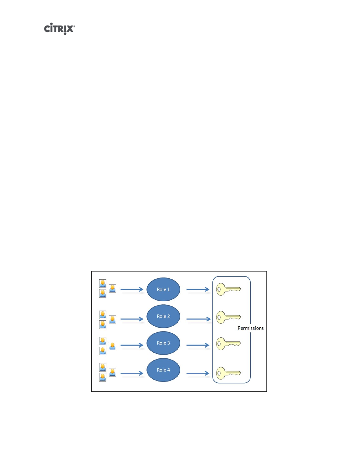
When you leave the domain (that is, disable Active Directory authentication and disconnect a pool or server
from its domain), any users who authenticated to the pool or server with Active Directory credentials are
disconnected.
Use XenCenter to leave an AD domain. See the XenCenter help for more information. Alternately run the
pool-disable-external-auth command, specifying the pool uuid if required.
Note:
Leaving the domain will not cause the host objects to be removed from the AD database. See this knowledge
base article for more information about this and how to remove the disabled host entries.
Role Based Access Control
Note:
The full RBAC feature is only available in Citrix XenServer Enterprise Edition or higher. To learn more about
upgrading XenServer, click here.
XenServer's Role Based Access Control (RBAC) allows you to assign users, roles, and permissions to
control who has access to your XenServer and what actions they can perform. The XenServer RBAC
system maps a user (or a group of users) to defined roles (a named set of permissions), which in turn have
associated XenServer permissions (the ability to perform certain operations).
As users are not assigned permissions directly, but acquire them through their assigned role, management
of individual user permissions becomes a matter of simply assigning the user to the appropriate role; this
simplifies common operations. XenServer maintains a list of authorized users and their roles.
RBAC allows you to easily restrict which operations different groups of users can perform - thus reducing
the probability of an accident by an inexperienced user.
To facilitate compliance and auditing, RBAC also provides an Audit Log feature and its corresponding
Workload Balancing Pool Audit Trail report.
RBAC depends on Active Directory for authentication services. Specifically, XenServer keeps a list of
authorized users based on Active Directory user and group accounts. As a result, you must join the pool to
the domain and add Active Directory accounts before you can assign roles.
7
Page 28

The local super user (LSU), or root, is a special user account used for system administration and has all
rights or permissions. In XenServer, the local super user is the default account at installation. The LSU
is authenticated via XenServer and not external authentication service, so if the external authentication
service fails, the LSU can still log in and manage the system. The LSU can always access the XenServer
physical host via SSH.
RBAC process
This is the standard process for implementing RBAC and assigning a user or group a role:
1. Join the domain. See Enabling external authentication on a pool
2. Add an Active Directory user or group to the pool. This becomes a subject. See the section called “To
add a subject to RBAC”.
3. Assign (or modify) the subject's RBAC role. See the section called “To assign an RBAC role to a created
subject”.
Roles
XenServer is shipped with the following six, pre-established roles:
• Pool Administrator (Pool Admin) – the same as being the local root. Can perform all operations.
Note:
The local super user (root) will always have the "Pool Admin" role. The Pool Admin role has the same
permissions as the local root.
• Pool Operator (Pool Operator) – can do everything apart from adding/removing users and modifying their
roles. This role is focused mainly on host and pool management (i.e.. creating storage, making pools,
managing the hosts etc.)
• Virtual Machine Power Administrator (VM Power Admin) – creates and manages Virtual Machines. This
role is focused on provisioning VMs for use by a VM operator.
• Virtual Machine Administrator (VM Admin) – similar to a VM Power Admin, but cannot migrate VMs or
perform snapshots.
• Virtual Machine Operator (VM Operator) – similar to VM Admin, but cannot create/destroy VMs – but can
perform start/stop lifecycle operations.
• Read-only (Read Only) – can view resource pool and performance data.
Note:
You cannot add, remove or modify roles in this version of XenServer.
Warning:
You can not assign the role of pool-admin to an AD group which has more than 500 members, if you want
users of the AD group to have SSH access.
For a summary of the permissions available for each role and more detailed information on the operations
available for each permission, see the section called “Definitions of RBAC roles and permissions”.
All XenServer users need to be allocated to an appropriate role. By default, all new users will be allocated
to the Pool Administrator role. It is possible for a user to be assigned to multiple roles; in that scenario, the
user will have the union of all the permissions of all their assigned roles.
8
Page 29
A user's role can be changed in two ways:
1. Modify the subject -> role mapping (this requires the assign/modify role permission, only available to a
Pool Administrator.)
2. Modify the user's containing group membership in Active Directory.
Definitions of RBAC roles and permissions
The following table summarizes which permissions are available for each role. For details on the operations
available for each permission, see Definitions of permissions.
Table 1. Permissions available for each role
Role
permissions
Assign/
modify roles
Log in to
(physical)
server
consoles
(through
SSH and
XenCenter)
Server
backup/
restore
Log out
active user
connections
Create and
dismiss
alerts
Pool Admin Pool
Operator
X
X
X
X X
X X
VM Power
Admin
VM Admin VM
Operator
Read Only
Cancel task
of any user
Pool
management
VM
advanced
operations
VM create/
destroy
operations
X X
X X
X X X
X X X X
9
Page 30
Role
permissions
Pool Admin Pool
Operator
VM Power
Admin
VM Admin VM
Operator
Read Only
VM change
CD media
View VM
consoles
XenCenter
view mgmt
ops
Cancel own
tasks
Read audit
logs
Configure,
Initialize,
Enable,
Disable
WLB
Apply WLB
Optimization
Recommendations
X X X X X
X X X X X
X X X X X
X X X X X X
X X X X X X
X X
X X
Modify WLB
Report
Subscriptions
Accept WLB
Placement
Recommendations
Display
WLB
Configuration
Generate
WLB
Reports
Connect to
pool and
read all pool
metadata
X X
X X X
X X X X X X
X X X X X
X X X X X X
Definitions of permissions
The following table provides additional details about permissions:
10
Page 31

Table 2. Definitions of permissions
Permission Allows Assignee To Rationale/Comments
Assign/modify roles • Add/remove users
• Add/remove roles from users
• Enable and disable Active
Directory integration (being
joined to the domain)
Log in to server consoles • Server console access
through ssh
• Server console access
through XenCenter
Server backup/restore VM
create/destroy operations
Log out active user connections • Ability to disconnect logged in
Create/dismiss alerts Warning: A user with this
• Back up and restore servers
• Back up and restore pool
metadata
users
This permission lets the user
grant himself or herself any
permission or perform any task.
Warning: This role lets the user
disable the Active Directory
integration and all subjects
added from Active Directory.
Warning: With access to a
root shell, the assignee could
arbitrarily reconfigure the entire
system, including RBAC.
The ability to restore a backup
lets the assignee revert RBAC
configuration changes.
permission can dismiss alerts for
the entire pool.
Cancel task of any user • Cancel any user's running
task
Note: The ability to view alerts
is part of the Connect to Pool
and read all pool metadata
permission.
This permission lets the user
request XenServer cancel an inprogress task initiated by any
user.
11
Page 32

Permission Allows Assignee To Rationale/Comments
Pool management • Set pool properties (naming,
default SRs)
• Enable, disable, and configure
HA
• Set per-VM HA restart
priorities
• Enable, disable, and configure
Workload Balancing (WLB)
• Add and remove server from
pool
• Emergency transition to
master
• Emergency master address
• Emergency recover slaves
• Designate new master
• Manage pool and server
certificates
• Patching
• Set server properties
• Configure server logging
• Enable and disable servers
• Shut down, reboot, and
power-on servers
• System status reports
• Apply license
• Live migration of all other
VMs on a server to another
server, due to either WLB,
Maintenance Mode, or HA
• Configure server management
interfaces
• Disable server management
• Delete crashdumps
This permission includes all the
actions required to maintain a
pool.
Note: If the management
interface is not functioning, no
logins can authenticate except
local root logins.
• Add, edit, and remove
networks
• Add, edit, and remove PBDs/
PIFs/VLANs/Bonds/SRs
• Add, remove, and retrieve
secrets
12
Page 33

Permission Allows Assignee To Rationale/Comments
VM advanced operations • Adjust VM memory (through
Dynamic Memory Control)
• Create a VM snapshot with
memory, take VM snapshots,
and roll-back VMs
• Migrate VMs
• Start VMs, including
specifying physical server
• Resume VMs
VM create/destroy operations • Install or delete
• Clone VMs
• Add, remove, and configure
virtual disk/CD devices
• Add, remove, and configure
virtual network devices
• Import/export VMs
• VM configuration change
VM change CD media • Eject current CD
• Insert new CD
This permission provides the
assignee with enough privileges
to start a VM on a different
server if they are not satisfied
with the server XenServer
selected.
VM change power state • Start VMs (automatic
placement)
• Shut down VMs
• Reboot VMs
• Suspend VMs
• Resume VMs (automatic
placement)
View VM consoles • See and interact with VM
consoles
Configure, Initialize, Enable,
Disable WLB
Apply WLB Optimization
Recommendations
Modify WLB Report
Subscriptions
• Configure WLB
• Initialize WLB and change
WLB servers
• Enable WLB
• Disable WLB
• Apply any optimization
recommendations that appear
in the WLB tab
• Change the WLB report
generated or its recipient
This permission does not
include start_on, resume_on,
and migrate, which are part of
the VM advanced operations
permission.
This permission does not let the
user view server consoles.
When a user's role does not
have this permission, this
functionality is not visible.
13
Page 34

Permission Allows Assignee To Rationale/Comments
Accept WLB Placement
Recommendations
Display WLB Configuration • View WLB settings for a pool
Generate WLB Reports • View and run WLB reports,
XenCenter view mgmt
operations
Cancel own tasks • Lets a user cancel their own
Read audit log • Download the XenServer
• Select one of the servers
Workload Balancing
recommends for placement
("star" recommendations)
as shown on the WLB tab
including the Pool Audit Trail
report
• Create and modify global
XenCenter folders
• Create and modify global
XenCenter custom fields
• Create and modify global
XenCenter searches
tasks
audit log
Folders, custom fields, and
searches are shared between all
users accessing the pool
Connect to pool and read all
pool metadata
Note:
In some cases, a Read Only user cannot move a resource into a folder in XenCenter, even after receiving an
elevation prompt and supplying the credentials of a more privileged user. In this case, log on to XenCenter
as the more privileged user and retry the action.
• Log in to pool
• View pool metadata
• View historical performance
data
• View logged in users
• View users and roles
• View messages
• Register for and receive
events
Working with RBAC using the xe CLI
To list all the available defined roles in XenServer
• Run the command: xe role-list
This command returns a list of the currently defined roles, for example:
14
Page 35

uuid( RO): 0165f154-ba3e-034e-6b27-5d271af109ba
name ( RO): pool-admin
description ( RO): The Pool Administrator role can do anything
uuid ( RO): b9ce9791-0604-50cd-0649-09b3284c7dfd
name ( RO): pool-operator
description ( RO): The Pool Operator can do anything but access Dom0 and mange subjects and roles
uuid( RO): 7955168d-7bec-10ed-105f-c6a7e6e63249
name ( RO): vm-power-admin
description ( RO): The VM Power Administrator role can do anything \
affecting VM properties across the pool
uuid ( RO): aaa00ab5-7340-bfbc-0d1b-7cf342639a6e
name ( RO): vm-admin
description ( RO): The VM Administrator role can do anything to a VM
uuid ( RO): fb8d4ff9-310c-a959-0613-54101535d3d5
name ( RO): vm-operator
description ( RO): The VM Operator role can do anything to an already
uuid ( RO): 7233b8e3-eacb-d7da-2c95-f2e581cdbf4e
name ( RO): read-only
description ( RO): The Read-Only role can only read values
Note:
The list of roles is static, so it is not possible to add or remove roles from it, only to list the available static ones.
To display a list of current subjects:
• Run the command xe subject-list
This will return a list of XenServer users, their uuid, and the roles they are associated with:
15
Page 36

uuid ( RO): bb6dd239-1fa9-a06b-a497-3be28b8dca44
subject-identifier ( RO): S-1-5-21-1539997073-1618981536-2562117463-2244
other-config (MRO): subject-name: example01\user_vm_admin; subject-upn: \
user_vm_admin@XENDT.NET; subject-uid: 1823475908; subject-gid: 1823474177; \
subject-sid: S-1-5-21-1539997073-1618981536-2562117463-2244; subject-gecos: \
user_vm_admin; subject-displayname: user_vm_admin; subject-is-group: false; \
subject-account-disabled: false; subject-account-expired: false; \
subject-account-locked: false;subject-password-expired: false
roles (SRO): vm-admin
uuid ( RO): 4fe89a50-6a1a-d9dd-afb9-b554cd00c01a
subject-identifier ( RO): S-1-5-21-1539997073-1618981536-2562117463-2245
other-config (MRO): subject-name: example02\user_vm_op; subject-upn: \
user_vm_op@XENDT.NET; subject-uid: 1823475909; subject-gid: 1823474177; \
subject-sid: S-1-5-21-1539997073-1618981536-2562117463-2245; \
subject-gecos: user_vm_op; subject-displayname: user_vm_op; \
subject-is-group: false; subject-account-disabled: false; \
subject-account-expired: false; subject-account-locked: \
false; subject-password-expired: false
roles (SRO): vm-operator
uuid ( RO): 8a63fbf0-9ef4-4fef-b4a5-b42984c27267
subject-identifier ( RO): S-1-5-21-1539997073-1618981536-2562117463-2242
other-config (MRO): subject-name: example03\user_pool_op; \
subject-upn: user_pool_op@XENDT.NET; subject-uid: 1823475906; \
subject-gid: 1823474177; subject-s id:
S-1-5-21-1539997073-1618981536-2562117463-2242; \
subject-gecos: user_pool_op; subject-displayname: user_pool_op; \
subject-is-group: false; subject-account-disabled: false; \
subject-account-expired: false; subject-account-locked: \
false; subject-password-expired: false
roles (SRO): pool-operator
To add a subject to RBAC
In order to enable existing AD users to use RBAC, you will need to create a subject instance within
XenServer, either for the AD user directly, or for one of their containing groups:
1. Run the command xe subject-add subject-name=<AD user/group>
This adds a new subject instance.
To assign an RBAC role to a created subject
Once you have added a subject, you can assign it to an RBAC role. You can refer to the role by either its
uuid or name:
1. Run the command:
xe subject-role-add uuid=<subject uuid> role-uuid=<role_uuid>
or
xe subject-role-add uuid=<subject uuid> role-name=<role_name>
For example, the following command adds a subject with the uuid b9b3d03b-3d10-79d3-8ed7a782c5ea13b4 to the Pool Administrator role:
xe subject-role-add uuid=b9b3d03b-3d10-79d3-8ed7-a782c5ea13b4 role-name=pool-admin
16
Page 37

To change a subject's RBAC role:
To change a user's role it is necessary to remove them from their existing role, and add them to a new role:
1. Run the commands:
xe subject-role-remove uuid=<subject uuid> role-name= \
<role_name_to_remove>
xe subject-role-add uuid=<subject uuid > role-name= \
<role_name_to_add>
To ensure that the new role takes effect, the user should be logged out and logged back in again (this requires
the "Logout Active User Connections" permission - available to a Pool Administrator or Pool Operator).
Warning:
Once you have added or removed a pool-admin subject, there can be a delay of a few seconds for ssh sessions
associated to this subject to be accepted by all hosts of the pool.
Auditing
The RBAC audit log will record any operation taken by a logged-in user.
• the message will explicitly record the Subject ID and user name associated with the session that invoked
the operation.
• if an operation is invoked for which the subject does not have authorization, this will be logged.
• if the operation succeeded then this is recorded; if the operation failed then the error code is logged.
Audit log xe CLI commands
xe audit-log-get [since=<timestamp>] filename=<output filename>
This command downloads to a file all the available records of the RBAC audit file in the pool. If the optional
parameter 'since' is present, then it only downloads the records from that specific point in time.
To obtain all audit records from the pool
Run the following command:
xe audit-log-get filename=/tmp/auditlog-pool-actions.out
To obtain audit records of the pool since a precise millisecond timestamp
Run the following command:
xe audit-log-get since=2009-09-24T17:56:20.530Z \
filename=/tmp/auditlog-pool-actions.out
To obtain audit records of the pool since a precise minute timestamp
Run the following command:
xe audit-log-get since=2009-09-24T17:56Z \
filename=/tmp/auditlog-pool-actions.out
17
Page 38

How does XenServer compute the roles for the session?
1. The subject is authenticated via the Active Directory server to verify which containing groups the subject
may also belong to.
2. XenServer then verifies which roles have been assigned both to the subject, and to its containing groups.
3. As subjects can be members of multiple Active Directory groups, they will inherit all of the permissions
of the associated roles.
In this illustration, since Subject 2 (Group 2) is the Pool Operator and User 1 is a member
of Group 2, when Subject 3 (User 1) tries to log in, he or she inherits both Subject
3 (VM Operator) and Group 2 (Pool Operator) roles. Since the Pool Operator role is
higher, the resulting role for Subject 3 (User 1) is Pool Operator and not VM Operator.
18
Page 39

XenServer hosts and resource pools
This chapter describes how resource pools can be created through a series of examples using the xe
command line interface (CLI). A simple NFS-based shared storage configuration is presented and a number
of simple VM management examples are discussed. Procedures for dealing with physical node failures are
also described.
Hosts and resource pools overview
A resource pool comprises multiple XenServer host installations, bound together into a single managed
entity which can host Virtual Machines. When combined with shared storage, a resource pool enables VMs
to be started on any XenServer host which has sufficient memory and then dynamically moved between
XenServer hosts while running with minimal downtime (XenMotion). If an individual XenServer host suffers
a hardware failure, then the administrator can restart the failed VMs on another XenServer host in the same
resource pool. If high availability (HA) is enabled on the resource pool, VMs will automatically be moved if
their host fails. Up to 16 hosts are supported per resource pool, although this restriction is not enforced.
A pool always has at least one physical node, known as the master. Only the master node exposes an
administration interface (used by XenCenter and the XenServer Command Line Interface, known as the xe
CLI); the master forwards commands to individual members as necessary.
Note:
If the pool's master fails, master re-election will only take place if High Availability is enabled.
Requirements for creating resource pools
A resource pool is a homogeneous (or heterogeneous with restrictions, see the section called “Creating
heterogeneous resource pools”) aggregate of one or more XenServer hosts, up to a maximum of 16. The
definition of homogeneous is:
• the CPUs on the server joining the pool are the same (in terms of vendor, model, and features) as the
CPUs on servers already in the pool.
• the server joining the pool is running the same version of XenServer software, at the same patch level,
as servers already in the pool
The software will enforce additional constraints when joining a server to a pool – in particular:
• it is not a member of an existing resource pool
• it has no shared storage configured
• there are no running or suspended VMs on the XenServer host which is joining
• there are no active operations on the VMs in progress, such as one shutting down
You must also check that the clock of the host joining the pool is synchronized to the same time as the
pool master (for example, by using NTP), that its management interface is not bonded (you can configure
this once the host has successfully joined the pool), and that its management IP address is static (either
configured on the host itself or by using an appropriate configuration on your DHCP server).
XenServer hosts in resource pools may contain different numbers of physical network interfaces and have
local storage repositories of varying size. In practice, it is often difficult to obtain multiple servers with the
exact same CPUs, and so minor variations are permitted. If you are sure that it is acceptable in your
environment for hosts with varying CPUs to be part of the same resource pool, then the pool joining operation
can be forced by passing a --force parameter.
19
Page 40

Note:
The requirement for a XenServer host to have a static IP address to be part of a resource pool also applies
to servers providing shared NFS or iSCSI storage for the pool.
Although not a strict technical requirement for creating a resource pool, the advantages of pools (for
example, the ability to dynamically choose on which XenServer host to run a VM and to dynamically move
a VM between XenServer hosts) are only available if the pool has one or more shared storage repositories.
If possible, postpone creating a pool of XenServer hosts until shared storage is available. Once shared
storage has been added, Citrix recommends that you move existing VMs whose disks are in local storage
into shared storage. This can be done using the xe vm-copy command or XenCenter.
Creating a resource pool
Resource pools can be created using either the XenCenter management console or the CLI. When you join
a new host to a resource pool, the joining host synchronizes its local database with the pool-wide one, and
inherits some settings from the pool:
• VM, local, and remote storage configuration is added to the pool-wide database. All of these will still be
tied to the joining host in the pool unless you explicitly take action to make the resources shared after
the join has completed.
• The joining host inherits existing shared storage repositories in the pool and appropriate PBD records are
created so that the new host can access existing shared storage automatically.
• Networking information is partially inherited to the joining host: the structural details of NICs, VLANs and
bonded interfaces are all inherited, but policy information is not. This policy information, which must be
re-configured, includes:
• the IP addresses of management NICs, which are preserved from the original configuration
• the location of the management interface, which remains the same as the original configuration. For
example, if the other pool hosts have their management interface on a bonded interface, then the joining
host must be explicitly migrated to the bond once it has joined. See To add NIC bonds to the pool master
and other hosts for details on how to migrate the management interface to a bond.
• Dedicated storage NICs, which must be re-assigned to the joining host from XenCenter or the CLI, and
the PBDs re-plugged to route the traffic accordingly. This is because IP addresses are not assigned
as part of the pool join operation, and the storage NIC is not useful without this configured correctly.
See the section called “Configuring a dedicated storage NIC” for details on how to dedicate a storage
NIC from the CLI.
To join XenServer hosts host1 and host2 into a resource pool using the CLI
1. Open a console on XenServer host host2.
2. Command XenServer host host2 to join the pool on XenServer host host1 by issuing the command:
xe pool-join master-address=<host1> master-username=<administrators_username> \
master-password=<password>
The master-address must be set to the fully-qualified domain name of XenServer host host1 and
the password must be the administrator password set when XenServer host host1 was installed.
Naming a resource pool
• XenServer hosts belong to an unnamed pool by default. To create your first resource pool, rename the
existing nameless pool. Use tab-complete to find the pool_uuid:
20
Page 41

xe pool-param-set name-label=<"New Pool"> uuid=<pool_uuid>
Creating heterogeneous resource pools
Note:
Heterogeneous resource pool creation is only available for XenServer Enterprise or Platinum editions. To
learn more about XenServer editions and to find out how to upgrade, visit the Citrix website here here
XenServer 5.6 simplifies expanding deployments over time by allowing disparate host hardware to be joined
into a resource pool, known as heterogeneous resource pools. Heterogeneous resource pools are made
possible by leveraging technologies in recent Intel (FlexMigration) and AMD (Extended Migration) CPUs that
provide CPU "masking" or "leveling". These features allow a CPU to be configured to appear as providing
a different make, model, or functionality than it actually does. This enables you to create pools of hosts with
disparate CPUs but still safely support live migrations.
Using XenServer to mask the CPU features of a new server, so that it will match the features of the existing
servers in a pool, requires the following:
• the CPUs of the server joining the pool must be of the same vendor (i.e.. AMD, Intel) as the CPUs on
servers already in the pool, though the specific type, (family, model and stepping numbers) need not be.
• the CPUs of the server joining the pool must support either Intel FlexMigration or AMD Enhanced
Migration.
• the features of the older CPUs must be a sub-set of the features of the CPUs of the server joining the pool.
• the server joining the pool is running the same version of XenServer software, with the same hotfixes
installed, as servers already in the pool.
• an Enterprise or Platinum license.
Creating heterogeneous resource pools is most easily done with XenCenterwhich will automatically suggest
using CPU masking when possible. Refer to the Pool Requirements section in the XenCenter help for more
details. To display the help in XenCenter press F1.
To add a heterogeneous XenServer host to a resource pool using the xe CLI
1. Find the CPU features of the Pool Master by running the xe host-get-cpu-features command.
2. On the new server, run the xe host-set-cpu-features command and copy and paste the Pool Master's
features into the features parameter. For example:
xe host-set-cpu-features features=<pool_master's_cpu_ features>
3. Restart the new server.
4. Run the xe pool-join command on the new server to join the pool.
To return a server with masked CPU features back to its normal capabilities, run the xe host-reset-cpu-
features command.
Note:
To display a list of all properties of the CPUs in a host, run the xe host-cpu-info command.
Adding shared storage
For a complete list of supported shared storage types, see the Storage chapter. This section demonstrates
how shared storage (represented as a storage repository) can be created on an existing NFS server.
21
Page 42

Adding NFS shared storage to a resource pool using the CLI
1. Open a console on any XenServer host in the pool.
2. Create the storage repository on <server:/path> by issuing the command
xe sr-create content-type=user type=nfs name-label=<"Example SR"> shared=true \
device-config:server=<server> \
device-config:serverpath=<path>
The device-config:server refers to the hostname of the NFS server and deviceconfig:serverpath refers to the path on the NFS server. Since shared is set to true, the shared
storage will be automatically connected to every XenServer host in the pool and any XenServer hosts
that subsequently join will also be connected to the storage. The Universally Unique Identifier (UUID)
of the created storage repository will be printed on the screen.
3. Find the UUID of the pool by the command
xe pool-list
4. Set the shared storage as the pool-wide default with the command
xe pool-param-set uuid=<pool_uuid> default-SR=<sr_uuid>
Since the shared storage has been set as the pool-wide default, all future VMs will have their disks
created on shared storage by default. See Storage for information about creating other types of shared
storage.
Removing a XenServer host from a resource pool
When a XenServer host is removed (ejected) from a pool, the machine is rebooted, reinitialized, and left in
a state equivalent to that after a fresh installation. It is important not to eject a XenServer host from a pool
if there is important data on the local disks.
To remove a host from a resource pool using the CLI
1. Open a console on any host in the pool.
2. Find the UUID of the host by running the command
xe host-list
3. Eject the required host from the pool:
xe pool-eject host-uuid=<host_uuid>
The XenServer host will be ejected and left in a freshly-installed state.
Warning:
Do not eject a host from a resource pool if it contains important data stored on its local disks. All of the data
will be erased upon ejection from the pool. If you wish to preserve this data, copy the VM to shared storage
on the pool first using XenCenter, or the xe vm-copy CLI command.
When a XenServer host containing locally stored VMs is ejected from a pool, those VMs will still be present
in the pool database and visible to the other XenServer hosts. They will not start until the virtual disks
associated with them have been changed to point at shared storage which can be seen by other XenServer
hosts in the pool, or simply removed. It is for this reason that you are strongly advised to move any
local storage to shared storage upon joining a pool, so that individual XenServer hosts can be ejected (or
physically fail) without loss of data.
22
Page 43

High Availability
This section explains the XenServer implementation of virtual machine high availability (HA), and how to
configure it using the xe CLI.
Note:
XenServer HA is only available with XenServer Advanced edition or above. To find out about XenServer
editions, visit the Citrix website here.
HA Overview
When HA is enabled, XenServer continually monitors the health of the hosts in a pool. The HA mechanism
automatically moves protected VMs to a healthy host if the current VM host fails. Additionally, if the host
that fails is the master, HA selects another host to take over the master role automatically, so that you can
continue to manage the XenServer pool.
To absolutely guarantee that a host is unreachable, a resource pool configured for high-availability uses
several heartbeat mechanisms to regularly check up on hosts. These heartbeats go through both the storage
interfaces (to the Heartbeat SR) and the networking interfaces (over the management interfaces). Both of
these heartbeat routes can be multi-homed for additional resilience to prevent false positives.
XenServer dynamically maintains a failover plan which details what to do if a set of hosts in a pool fail at any
given time. An important concept to understand is the host failures to tolerate value, which is defined as part
of HA configuration. This determines the number of failures that is allowed without any loss of service. For
example, if a resource pool consisted of 16 hosts, and the tolerated failures is set to 3, the pool calculates a
failover plan that allows for any 3 hosts to fail and still be able to restart VMs on other hosts. If a plan cannot
be found, then the pool is considered to be overcommitted. The plan is dynamically recalculated based on
VM lifecycle operations and movement. Alerts are sent (either through XenCenter or e-mail) if changes (for
example the addition on new VMs to the pool) cause your pool to become overcommitted.
Overcommitting
A pool is overcommitted if the VMs that are currently running could not be restarted elsewhere following a
user-defined number of host failures.
This would happen if there was not enough free memory across the pool to run those VMs following failure.
However there are also more subtle changes which can make HA guarantees unsustainable: changes to
Virtual Block Devices (VBDs) and networks can affect which VMs may be restarted on which hosts. Currently
it is not possible for XenServer to check all actions before they occur and determine if they will cause
violation of HA demands. However an asynchronous notification is sent if HA becomes unsustainable.
Overcommitment Warning
If you attempt to start or resume a VM and that action causes the pool to be overcommitted, a warning
alert is raised. This warning is displayed in XenCenter and is also available as a message instance through
the Xen API. The message may also be sent to an email address if configured. You will then be allowed
to cancel the operation, or proceed anyway. Proceeding causes the pool to become overcommitted. The
amount of memory used by VMs of different priorities is displayed at the pool and host levels.
Host Fencing
If a server failure occurs such as the loss of network connectivity or a problem with the control stack
is encountered, the XenServer host self-fences to ensure that the VMs are not running on two servers
simultaneously. When a fence action is taken, the server immediately and abruptly restarts, causing all VMs
23
Page 44

running on it to be stopped. The other servers will detect that the VMs are no longer running and the VMs
will be restarted according to the restart priorities assign to them. The fenced server will enter a reboot
sequence, and when it has restarted it will try to re-join the resource pool.
Configuration Requirements
To use the HA feature, you need:
• Shared storage, including at least one iSCSI or Fibre Channel LUN of size 356MB or greater - the
heartbeat SR. The HA mechanism creates two volumes on the heartbeat SR:
4MB heartbeat volume
Used for heartbeating.
256MB metadata volume
Stores pool master metadata to be used in the case of master failover.
If you are using a NetApp or EqualLogic SR, manually provision an iSCSI LUN on the array to use as
the heartbeat SR.
• A XenServer pool (this feature provides high availability at the server level within a single resource pool).
• Enterprise licenses on all hosts.
• Static IP addresses for all hosts.
Warning:
Should the IP address of a server change while HA is enabled, HA will assume that the host's network has
failed, and will probably fence the host and leave it in an unbootable state. To remedy this situation, disable
HA using the host-emergency-ha-disable command, reset the pool master using pool-emergency-reset-
master, and then re-enable HA.
For a VM to be protected by the HA feature, it must be agile. This means that:
• it must have its virtual disks on shared storage (any type of shared storage may be used; the iSCSI or
Fibre Channel LUN is only required for the storage heartbeat and can be used for virtual disk storage if
you prefer, but this is not necessary)
• it must not have a connection to a local DVD drive configured
• it should have its virtual network interfaces on pool-wide networks.
Citrix strongly recommends the use of a bonded management interface on the servers in the pool if HA is
enabled, and multipathed storage for the heartbeat SR.
If you create VLANs and bonded interfaces from the CLI, then they may not be plugged in and active despite
being created. In this situation, a VM can appear to be not agile, and cannot be protected by HA. If this
occurs, use the CLI pif-plug command to bring the VLAN and bond PIFs up so that the VM can become
agile. You can also determine precisely why a VM is not agile by using the xe diagnostic-vm-status CLI
command to analyze its placement constraints, and take remedial action if required.
Restart priorities
Virtual machines are assigned a restart priority and a flag that indicates whether they should be protected
by HA or not. When HA is enabled, every effort is made to keep protected virtual machines live. If a restart
priority is specified, any protected VM that is halted will be started automatically. If a server fails then the
VMs on it will be started on another server.
The possible restart priorities are:
24
Page 45

1 | 2 | 3
when a pool is overcommited the HA mechanism will attempt to restart protected VMs with the lowest
restart priority first
best-effort
VMs with this priority setting will be restarted only when the system has attempted to restart protected
VMs
ha-always-run=false
VMs with this parameter set will not be restarted
The restart priorities determine the order in which VMs are restarted when a failure occurs. In a given
configuration where a number of server failures greater than zero can be tolerated (as indicated in the HA
panel in the GUI, or by the ha-plan-exists-for field on the pool object on the CLI), the VMs that have
restart priorities 1, 2 or 3 are guaranteed to be restarted given the stated number of server failures. VMs
with a best-effort priority setting are not part of the failover plan and are not guaranteed to be kept
running, since capacity is not reserved for them. If the pool experiences server failures and enters a state
where the number of tolerable failures drops to zero, the protected VMs will no longer be guaranteed to be
restarted. If this condition is reached, a system alert will be generated. In this case, should an additional
failure occur, all VMs that have a restart priority set will behave according to the best-effort behavior.
If a protected VM cannot be restarted at the time of a server failure (for example, if the pool was
overcommitted when the failure occurred), further attempts to start this VM will be made as the state of
the pool changes. This means that if extra capacity becomes available in a pool (if you shut down a nonessential VM, or add an additional server, for example), a fresh attempt to restart the protected VMs will
be made, which may now succeed.
Note:
No running VM will ever be stopped or migrated in order to free resources for a VM with always-
run=true to be restarted.
Enabling HA on a XenServer pool
HA can be enabled on a pool using either XenCenter or the command-line interface. In either case, you
will specify a set of priorities that determine which VMs should be given highest restart priority when a pool
is overcommitted.
Warning:
When HA is enabled, some operations that would compromise the plan for restarting VMs may be disabled,
such as removing a server from a pool. To perform these operations, HA can be temporarily disabled, or
alternately, VMs protected by HA made unprotected.
Enabling HA using the CLI
1. Verify that you have a compatible Storage Repository (SR) attached to your pool. iSCSI or Fibre
Channel are compatible SR types. Please refer to the reference guide for details on how to configure
such a storage repository using the CLI.
2. For each VM you wish to protect, set a restart priority. You can do this as follows:
xe vm-param-set uuid=<vm_uuid> ha-restart-priority=<1> ha-always-run=true
3. Enable HA on the pool:
xe pool-ha-enable heartbeat-sr-uuids=<sr_uuid>
25
Page 46

4. Run the pool-ha-compute-max-host-failures-to-tolerate command. This command returns the
maximum number of hosts that can fail before there are insufficient resources to run all the protected
VMs in the pool.
xe pool-ha-compute-max-host-failures-to-tolerate
The number of failures to tolerate determines when an alert is sent: the system will recompute a failover
plan as the state of the pool changes and with this computation the system identifies the capacity of
the pool and how many more failures are possible without loss of the liveness guarantee for protected
VMs. A system alert is generated when this computed value falls below the specified value for ha-
host-failures-to-tolerate.
5. Specify the number of failures to tolerate parameter. This should be less than or equal to the computed
value:
xe pool-param-set ha-host-failures-to-tolerate=<2>
Removing HA protection from a VM using the CLI
To disable HA features for a VM, use the xe vm-param-set command to set the ha-always-run parameter
to false. This does not clear the VM restart priority settings. You can enable HA for a VM again by setting
the ha-always-run parameter to true.
Recovering an unreachable host
If for some reason a host cannot access the HA statefile, it is possible that a host may become unreachable.
To recover your XenServer installation it may be necessary to disable HA using the host-emergency-ha-
disable command:
xe host-emergency-ha-disable --force
If the host was the pool master, then it should start up as normal with HA disabled. Slaves should reconnect
and automatically disable HA. If the host was a Pool slave and cannot contact the master, then it may be
necessary to force the host to reboot as a pool master (xe pool-emergency-transition-to-master) or to
tell it where the new master is (xe pool-emergency-reset-master):
xe pool-emergency-transition-to-master uuid=<host_uuid>
xe pool-emergency-reset-master master-address=<new_master_hostname>
When all hosts have successfully restarted, re-enable HA:
xe pool-ha-enable heartbeat-sr-uuid=<sr_uuid>
Shutting down a host when HA is enabled
When HA is enabled special care needs to be taken when shutting down or rebooting a host to prevent
the HA mechanism from assuming that the host has failed. To shutdown a host cleanly in an HA-enabled
environment, first disable the host, then evacuate the host and finally shutdown the host using either
XenCenter or the CLI. To shutdown a host in an HA-enabled environment on the command line:
xe host-disable host=<host_name>
xe host-evacuate uuid=<host_uuid>
xe host-shutdown host=<host_name>
Shutting down a VM when it is protected by HA
When a VM is protected under a HA plan and set to restart automatically, it cannot be shut down while this
protection is active. To shut down a VM, first disable its HA protection and then execute the CLI command.
26
Page 47

XenCenter offers you a dialog box to automate disabling the protection if you click on the Shutdown button
of a protected VM.
Note:
If you shut down a VM from within the guest, and the VM is protected, it is automatically restarted under
the HA failure conditions. This helps ensure that operator error (or an errant program that mistakenly shuts
down the VM) does not result in a protected VM being left shut down accidentally. If you want to shut this
VM down, disable its HA protection first.
Host Power On
Powering on hosts remotely
You can use the XenServer Host Power On feature to turn a server on and off remotely, either from
XenCenter or by using the CLI. When using Workload Balancing (WLB), you can configure Workload
Balancing to turn hosts on and off automatically as VMs are consolidated or brought back online.
To enable host power, the server must have one of the following power-control solutions:
• Wake On LAN enabled network card.
• Dell Remote Access Cards (DRAC). To use XenServer with DRAC, you must install the Dell
supplemental pack to get DRAC support. DRAC support requires installing RACADM command-line utility
on the server with the remote access controller and enable DRAC and its interface. RACADM is often
included in the DRAC management software. For more information, see Dell’s DRAC documentation.
• Hewlett-Packard Integrated Lights-Out (iLO). To use XenServer with iLO, you must enable iLO on the
host and connect interface to the network. For more information, see HP’s iLO documentation.
• A custom script based on the XenAPI that enables you to turn the power on and off through XenServer.
For more information, see [Configuring a Custom Script for XenServer's Host Power On Feature].
Using the Host Power On feature requires three tasks:
1. Ensuring the hosts in the pool support controlling the power remotely (that is, they have Wake-on-LAN
functionality, a DRAC or iLO card, or you created custom script).
2. Enabling the Host Power On functionality using the CLI or XenCenter.
3. (Optional.) Configuring automatic Host Power On functionality in Workload Balancing. See the section
called “Optimizing and Managing Power Automatically ”.
Note:
You must enable Host Power On and configure the Power Management feature in Workload Balancing before
Workload Balancing can turn hosts on and off automatically.
Using the CLI to Manage Host Power On
You can manage the Host Power On feature using either the CLI or XenCenter. This topic provides
information about managing it with the CLI.
Host Power On is enabled at the host level (that is, on each XenServer).
After you enable Host Power On, you can turn hosts on using either the CLI or XenCenter.
After configuration, you can configure and run the Workload Balancing Automation and Host
Power Management features, as described in the Workload Balancing chapter. To enable Workload
27
Page 48

Balancing's Host Power Management feature, use the pool-send-wlb-configuration command with the
ParticipatesInPowerManagement=<true> \ config:set_host_configuration=<true> arguments.
To enable Host Power On using the CLI
1. Run the command:
xe host-set-power-on host=<host uuid>\
power-on-mode=("" , "wake-on-lan",
"iLO", "DRAC","custom")
power-on-config:key=value
For iLO and DRAC the keys are power_on_ip, power_on_user, power_on_password. Use
power_on_password to specify the password if you are using the secret feature.
To turn on hosts remotely using the CLI
1. Run the command:
xe host-power-on host=<host uuid>
Configuring a Custom Script for XenServer's Host Power On Feature
If your servers' remote-power solution uses a protocol that is not supported by default (such as Wake-OnRing or Intel Active Management Technology), you can create a custom Linux Python script to turn on your
XenServer computers remotely. However, you can also can create custom scripts for iLO, DRAC, and WakeOn-LAN remote-power solutions.
This topic provides information about configuring a custom script for Host Power On using the key/value
pairs associated with the XenServer API call host.power_on.
When you create a custom script, run it from the command line each time you want to control power remotely
on XenServer. Alternatively, you can specify it in XenCenter and use the XenCenter UI features to interact
with it.
The XenServer API is documented in the document, the [Citrix XenServer Management API], which is
available from the Citrix Web site.
Note:
Do not modify the scripts provided by default in the /etc/xapi.d/plugins/ directory. You can include new
scripts in this directory, but you should never modify the scripts contained in that directory after installation.
Key/Value Pairs
To use Host Power On, you must configure the host.power_on_mode and host.power_on_config keys. Their
values are provided below.
There is also an API call that lets you set these fields all at once:
void host.set_host_power_on_mode(string mode, Dictionary<string,string> config)
host.power_on_mode
• Definition: This contains key/value pairs to specify the type of remote-power solution (for example, Dell
DRAC).
28
Page 49

• Possible values:
• An empty string, representing power-control disabled
• "iLO". Lets you specify HP iLO.
• "DRAC". Lets you specify Dell DRAC. To use DRAC, you must have already installed the Dell
supplemental pack.
• "wake-on-lan". Lets you specify Wake on LAN.
• Any other name (used to specify a custom power-on script). This option is used to specify a custom
script for power management.
• Type: string
host.power_on_config
• Definition: This contains key/value pairs for mode configuration. Provides additional information for
• Possible values:
• If you configured iLO or DRAC as the type of remote-power solution, you must also specify one of the
following keys:
• "power_on_ip". This is the IP address you specified configured to communicate with the powercontrol card. Alternatively, you can enter the domain name for the network interface where iLO or
DRAC is configured.
• "power_on_user". This is the iLO or DRAC user name that is associated with the management
processor, which you may or may not have changed from its factory default settings.
• "power_on_password_secret". Specifies using the secrets feature to secure your password.
• To use the secrets feature to store your password, specify the key "power_on_password_secret".
• Type: Map (string,string)
Sample Script
This sample script imports the XenServer API, defines itself as a custom script, and then passes parameters
specific to the host you want to control remotely. You must define the parameters session, remote_host,
and power_on_config in all custom scripts.
The result is only displayed when the script is unsuccessful.
import XenAPI
def custom(session,remote_host,
power_on_config):
result="Power On Not Successful"
for key in power_on_config.keys():
result=result+"
key="+key+"
value="+power_on_config[key]
return result
Note:
After creation, save the script in the /etc/xapi.d/plugins with a .py extension.
29
Page 50

Storage
This chapter discusses the framework for storage abstractions. It describes the way physical storage
hardware of various kinds is mapped to VMs, and the software objects used by the XenServer host
API to perform storage-related tasks. Detailed sections on each of the supported storage types include
procedures for creating storage for VMs using the CLI, with type-specific device configuration options,
generating snapshots for backup purposes and some best practices for managing storage in XenServer
host environments. Finally, the virtual disk QoS (quality of service) settings are described.
Storage Overview
This section explains what the XenServer storage objects are and how they are related to each other.
Storage Repositories (SRs)
XenServer defines a container called a storage repository (SR) to describe a particular storage target, in
which Virtual Disk Images (VDIs) are stored. A VDI is a disk abstraction which contains the contents of a
virtual disk.
The interface to storage hardware allows VDIs to be supported on a large number of SR types. The
XenServer SR is very flexible, with built-in support for IDE, SATA, SCSI and SAS drives locally connected,
and iSCSI, NFS, SAS and Fibre Channel remotely connected. The SR and VDI abstractions allow advanced
storage features such as sparse provisioning, VDI snapshots, and fast cloning to be exposed on storage
targets that support them. For storage subsystems that do not inherently support advanced operations
directly, a software stack is provided based on Microsoft's Virtual Hard Disk (VHD) specification which
implements these features.
Each XenServer host can use multiple SRs and different SR types simultaneously. These SRs can be shared
between hosts or dedicated to particular hosts. Shared storage is pooled between multiple hosts within a
defined resource pool. A shared SR must be network accessible to each host. All hosts in a single resource
pool must have at least one shared SR in common.
SRs are storage targets containing virtual disk images (VDIs). SR commands provide operations for
creating, destroying, resizing, cloning, connecting and discovering the individual VDIs that they contain.
A storage repository is a persistent, on-disk data structure. For SR types that use an underlying block device,
the process of creating a new SR involves erasing any existing data on the specified storage target. Other
storage types such as NFS, Netapp, Equallogic and StorageLink SRs, create a new container on the storage
array in parallel to existing SRs.
CLI operations to manage storage repositories are described in the section called “SR commands”.
Virtual Disk Images (VDIs)
Virtual Disk Images are a storage abstraction that is presented to a VM. VDIs are the fundamental unit of
virtualized storage in XenServer. Similar to SRs, VDIs are persistent, on-disk objects that exist independently
of XenServer hosts. CLI operations to manage VDIs are described in the section called “VDI commands”.
The actual on-disk representation of the data differs by the SR type and is managed by a separate storage
plugin interface for each SR, called the SM API.
Physical Block Devices (PBDs)
Physical Block Devices represent the interface between a physical server and an attached SR. PBDs
are connector objects that allow a given SR to be mapped to a XenServer host. PBDs store the device
30
Page 51

configuration fields that are used to connect to and interact with a given storage target. For example, NFS
device configuration includes the IP address of the NFS server and the associated path that the XenServer
host mounts. PBD objects manage the run-time attachment of a given SR to a given XenServer host. CLI
operations relating to PBDs are described in the section called “PBD commands”.
Virtual Block Devices (VBDs)
Virtual Block Devices are connector objects (similar to the PBD described above) that allows mappings
between VDIs and VMs. In addition to providing a mechanism for attaching (also called plugging) a VDI
into a VM, VBDs allow for the fine-tuning of parameters regarding QoS (quality of service), statistics, and
the bootability of a given VDI. CLI operations relating to VBDs are described in the section called “VBD
commands”.
Summary of Storage objects
The following image is a summary of how the storage objects presented so far are related:
Graphical overview of storage repositories and related objects
Virtual Disk Data Formats
In general, there are three types of mapping of physical storage to a VDI:
• File-based VHD on a Filesystem; VM images are stored as thin-provisioned VHD format files on either a
local non-shared Filesystem (EXT type SR) or a shared NFS target (NFS type SR)
• Logical Volume-based VHD on a LUN; The default XenServer blockdevice-based storage inserts a Logical
Volume manager on a disk, either a locally attached device (LVM type SR) or a SAN attached LUN over
either Fibre Channel (LVMoHBA type SR), iSCSI (LVMoISCSI type SR) or SAS (LVMoHBA type Sr).
VDIs are represented as volumes within the Volume manager and stored in VHD format to allow thin
provisioning of reference nodes on snapshot and clone.
• LUN per VDI; LUNs are directly mapped to VMs as VDIs by SR types that provide an array-specific plugin
(Netapp, Equallogic or StorageLink type SRs). The array storage abstraction therefore matches the VDI
storage abstraction for environments that manage storage provisioning at an array level.
31
Page 52

VHD-based VDIs
VHD files may be chained, allowing two VDIs to share common data. In cases where a VHD-backed VM is
cloned, the resulting VMs share the common on-disk data at the time of cloning. Each proceeds to make its
own changes in an isolated copy-on-write (CoW) version of the VDI. This feature allows VHD-based VMs
to be quickly cloned from templates, facilitating very fast provisioning and deployment of new VMs.
The VHD format used by LVM-based and File-based SR types in XenServer uses sparse provisioning. The
image file is automatically extended in 2MB chunks as the VM writes data into the disk. For File-based VHD,
this has the considerable benefit that VM image files take up only as much space on the physical storage
as required. With LVM-based VHD the underlying logical volume container must be sized to the virtual size
of the VDI, however unused space on the underlying CoW instance disk is reclaimed when a snapshot or
clone occurs. The difference between the two behaviors can be characterized in the following way:
• For LVM-based VHDs, the difference disk nodes within the chain consume only as much data as has
been written to disk but the leaf nodes (VDI clones) remain fully inflated to the virtual size of the disk.
Snapshot leaf nodes (VDI snapshots) remain deflated when not in use and can be attached Read-only
to preserve the deflated allocation. Snapshot nodes that are attached Read-Write will be fully inflated on
attach, and deflated on detach.
• For file-based VHDs, all nodes consume only as much data as has been written, and the leaf node files
grow to accommodate data as it is actively written. If a 100GB VDI is allocated for a new VM and an OS
is installed, the VDI file will physically be only the size of the OS data that has been written to the disk,
plus some minor metadata overhead.
When cloning VMs based off a single VHD template, each child VM forms a chain where new changes
are written to the new VM, and old blocks are directly read from the parent template. If the new VM was
converted into a further template and more VMs cloned, then the resulting chain will result in degraded
performance. XenServer supports a maximum chain length of 30, but it is generally not recommended that
you approach this limit without good reason. If in doubt, you can always "copy" the VM using XenServer or
the vm-copy command, which resets the chain length back to 0.
VHD Chain Coalescing
VHD images support chaining, which is the process whereby information shared between one or more VDIs
is not duplicated. This leads to a situation where trees of chained VDIs are created over time as VMs and
their associated VDIs get cloned. When one of the VDIs in a chain is deleted, XenServer rationalizes the
other VDIs in the chain to remove unnecessary VDIs.
This coalescing process runs asynchronously. The amount of disk space reclaimed and the time taken to
perform the process depends on the size of the VDI and the amount of shared data. Only one coalescing
process will ever be active for an SR. This process thread runs on the SR master host.
If you have critical VMs running on the master server of the pool and experience occasional slow IO due
to this process, you can take steps to mitigate against this:
• Migrate the VM to a host other than the SR master
• Set the disk IO priority to a higher level, and adjust the scheduler. See the section called “Virtual disk
QoS settings” for more information.
Space Utilization
Space utilization is always reported based on the current allocation of the SR, and may not reflect the
amount of virtual disk space allocated. The reporting of space for LVM-based SRs versus File-based SRs
will also differ given that File-based VHD supports full thin provisioning, while the underlying volume of an
LVM-based VHD will be fully inflated to support potential growth for writeable leaf nodes. Space utilization
32
Page 53

reported for the SR will depend on the number of snapshots, and the amount of difference data written to
a disk between each snapshot.
LVM-based space utilization differs depending on whether an LVM SR is upgraded or created as a new SR in
XenServer. Upgraded LVM SRs will retain a base node that is fully inflated to the size of the virtual disk, and
any subsequent snapshot or clone operations will provision at least one additional node that is fully inflated.
For new SRs, in contrast, the base node will be deflated to only the data allocated in the VHD overlay.
When VHD-based VDIs are deleted, the space is marked for deletion on disk. Actual removal of allocated
data may take some time to occur as it is handled by the coalesce process that runs asynchronously and
independently for each VHD-based SR.
LUN-based VDIs
Mapping a raw LUN as a Virtual Disk image is typically the most high-performance storage method. For
administrators that want to leverage existing storage SAN infrastructure such as Netapp, Equallogic or
StorageLink accessible arrays, the array snapshot, clone and thin provisioning capabilities can be exploited
directly using one of the array specific adapter SR types (Netapp, Equallogic or StorageLink). The virtual
machine storage operations are mapped directly onto the array APIs using a LUN per VDI representation.
This includes activating the data path on demand such as when a VM is started or migrated to another host.
Managed NetApp LUNs are accessible using the NetApp SR driver type, and are hosted on a Network
Appliance device running a version of Ontap 7.0 or greater. LUNs are allocated and mapped dynamically
to the host using the XenServer host management framework.
EqualLogic storage is accessible using the EqualLogic SR driver type, and is hosted on an EqualLogic
storage array running a firmware version of 4.0 or greater. LUNs are allocated and mapped dynamically to
the host using the XenServer host management framework.
For further information on StorageLink supported array systems and the various capabilities in each case,
please refer to the StorageLink documentation directly.
Storage configuration
This section covers creating storage repository types and making them available to a XenServer host. The
examples provided pertain to storage configuration using the CLI, which provides the greatest flexibility. See
the XenCenter Help for details on using the New Storage Repository wizard.
Creating Storage Repositories
This section explains how to create Storage Repositories (SRs) of different types and make them available
to a XenServer host. The examples provided cover creating SRs using the xe CLI. See the XenCenter help
for details on using the New Storage Repository wizard to add SRs using XenCenter.
Note:
Local SRs of type lvm and ext can only be created using the xe CLI. After creation all SR types can be
managed by either XenCenter or the xe CLI.
There are two basic steps involved in creating a new storage repository for use on a XenServer host using
the CLI:
1. Probe the SR type to determine values for any required parameters.
2. Create the SR to initialize the SR object and associated PBD objects, plug the PBDs, and activate the SR.
These steps differ in detail depending on the type of SR being created. In all examples the sr-create
command returns the UUID of the created SR if successful.
33
Page 54

SRs can also be destroyed when no longer in use to free up the physical device, or forgotten to detach
the SR from one XenServer host and attach it to another. See the section called “Destroying or forgetting
a SR” for details.
Note:
When specifying StorageLink configuration for a XenServer host or pool, supply either the default credentials
of username: admin and password: storagelink, or any custom credentials specified during installation
of the StorageLink Gateway service. Unlike StorageLink Manager, XenCenter does not supply the default
credentials automatically.
Upgrading LVM storage from XenServer 5.0 or earlier
See the XenServer Installation Guide for information on upgrading LVM storage to enable the latest features.
Local, LVM on iSCSI, and LVM on HBA storage types from older (XenServer 5.0 and before) product
versions will need to be upgraded before they will support snapshot and fast clone.
Warning:
SR upgrade of SRs created in version 5.0 or before requires the creation of a 4MB metadata volume. Please
ensure that there are at least 4MB of free space on your SR before attempting to upgrade the storage.
Note:
Upgrade is a one-way operation so Citrix recommends only performing the upgrade when you are certain
the storage will no longer need to be attached to a pool running an older software version.
LVM performance considerations
The snapshot and fast clone functionality provided in XenServer 5.5 and later for LVM-based SRs comes
with an inherent performance overhead. In cases where optimal performance is desired, XenServer
supports creation of VDIs in the raw format in addition to the default VHD format. The XenServer snapshot
functionality is not supported on raw VDIs.
Note:
Non-transportable snapshots using the default Windows VSS provider will work on any type of VDI.
Warning:
Do not try to snapshot a VM that has type=raw disks attached. This could result in a partial snapshot being
created. In this situation, you can identify the orphan snapshot VDIs by checking the snapshot-of field
and then deleting them.
VDI types
In general, VHD format VDIs will be created. You can opt to use raw at the time you create the VDI; this can
only be done using the xe CLI. After software upgrade from a previous XenServer version, existing data
will be preserved as backwards-compatible raw VDIs but these are special-cased so that snapshots can be
taken of them once you have allowed this by upgrading the SR. Once the SR has been upgraded and the
first snapshot has been taken, you will be accessing the data through a VHD format VDI.
To check if an SR has been upgraded, verify that its sm-config:use_vhd key is true. To check if a
VDI was created with type=raw, check its sm-config map. The sr-param-list and vdi-param-list xe
commands can be used respectively for this purpose.
Creating a raw virtual disk using the xe CLI
1. Run the following command to create a VDI given the UUID of the SR you want to place the virtual disk in:
34
Page 55

xe vdi-create sr-uuid=<sr-uuid> type=user virtual-size=<virtual-size> \
name-label=<VDI name> sm-config:type=raw
2. Attach the new virtual disk to a VM and use your normal disk tools within the VM to partition and format,
or otherwise make use of the new disk. You can use the vbd-create command to create a new VBD to
map the virtual disk into your VM.
Converting between VDI formats
It is not possible to do a direct conversion between the raw and VHD formats. Instead, you can create a new
VDI (either raw, as described above, or VHD if the SR has been upgraded or was created on XenServer
5.5 or later) and then copy data into it from an existing volume. Citrix recommends that you use the xe CLI
to ensure that the new VDI has a virtual size at least as big as the VDI you are copying from (by checking
its virtual-size field, for example by using the vdi-param-list command). You can then attach this new VDI
to a VM and use your preferred tool within the VM (standard disk management tools in Windows, or the dd
command in Linux) to do a direct block-copy of the data. If the new volume is a VHD volume, it is important
to use a tool that can avoid writing empty sectors to the disk so that space is used optimally in the underlying
storage repository — in this case a file-based copy approach may be more suitable.
Probing an SR
The sr-probe command can be used in two ways:
1. To identify unknown parameters for use in creating a SR.
2. To return a list of existing SRs.
In both cases sr-probe works by specifying an SR type and one or more device-config parameters for
that SR type. When an incomplete set of parameters is supplied the sr-probe command returns an error
message indicating parameters are missing and the possible options for the missing parameters. When a
complete set of parameters is supplied a list of existing SRs is returned. All sr-probe output is returned
as XML.
For example, a known iSCSI target can be probed by specifying its name or IP address, and the set of IQNs
available on the target will be returned:
xe sr-probe type=lvmoiscsi device-config:target=<192.168.1.10>
Error code: SR_BACKEND_FAILURE_96
Error parameters: , The request is missing or has an incorrect target IQN parameter, \
<?xml version="1.0" ?>
<iscsi-target-iqns>
<TGT>
<Index>
0
</Index>
<IPAddress>
192.168.1.10
</IPAddress>
<TargetIQN>
iqn.192.168.1.10:filer1
</TargetIQN>
</TGT>
</iscsi-target-iqns>
Probing the same target again and specifying both the name/IP address and desired IQN returns the set
of SCSIids (LUNs) available on the target/IQN.
35
Page 56

xe sr-probe type=lvmoiscsi device-config:target=192.168.1.10 \
device-config:targetIQN=iqn.192.168.1.10:filer1
Error code: SR_BACKEND_FAILURE_107
Error parameters: , The SCSIid parameter is missing or incorrect, \
<?xml version="1.0" ?>
<iscsi-target>
<LUN>
<vendor>
IET
</vendor>
<LUNid>
0
</LUNid>
<size>
42949672960
</size>
<SCSIid>
149455400000000000000000002000000b70200000f000000
</SCSIid>
</LUN>
</iscsi-target>
Probing the same target and supplying all three parameters will return a list of SRs that exist on the LUN,
if any.
xe sr-probe type=lvmoiscsi device-config:target=192.168.1.10 \
device-config:targetIQN=192.168.1.10:filer1 \
device-config:SCSIid=149455400000000000000000002000000b70200000f000000
<?xml version="1.0" ?>
<SRlist>
<SR>
<UUID>
3f6e1ebd-8687-0315-f9d3-b02ab3adc4a6
</UUID>
<Devlist>
/dev/disk/by-id/scsi-149455400000000000000000002000000b70200000f000000
</Devlist>
</SR>
</SRlist>
The following parameters can be probed for each SR type:
SR type device-config parameter, in order of
dependency
Can be
probed?
Required for sr-create?
lvmoiscsi target No Yes
chapuser No No
chappassword No No
targetIQN Yes Yes
SCSIid Yes Yes
lvmohba SCSIid Yes Yes
36
Page 57

SR type device-config parameter, in order of
dependency
Can be
probed?
Required for sr-create?
netapp target No Yes
username No Yes
password No Yes
chapuser No No
chappassword No No
aggregate No
*
Yes
FlexVols No No
allocation No No
asis No No
nfs server No Yes
serverpath Yes Yes
lvm device No Yes
ext device No Yes
equallogic target No Yes
username No Yes
password No Yes
chapuser No No
chappassword No No
storagepool No
†
Yes
cslg target No Yes
storageSystemId Yes Yes
storagePoolId Yes Yes
username No No
password No No
cslport No No
chapuser No No
chappassword No No
37
‡
‡
‡
‡
‡
Page 58

SR type device-config parameter, in order of
dependency
Can be
probed?
Required for sr-create?
provision-type Yes No
protocol Yes No
provision-options Yes No
raid-type Yes No
*
Aggregate probing is only possible at sr-create time. It needs to be done there so that the aggregate can be specified at the point that the SR is created.
†
Storage pool probing is only possible at sr-create time. It needs to be done there so that the aggregate can be specified at the point that the SR
is created.
‡
If the username, password, or port configuration of the StorageLink service are changed from the default value then the appropriate parameter
and value must be specified.
Storage Multipathing
Dynamic multipathing support is available for Fibre Channel and iSCSI storage backends. By default, it uses
round-robin mode load balancing, so both routes have active traffic on them during normal operation. You
can enable multipathing in XenCenter or on the xe CLI.
Before attempting to enable multipathing, verify that multiple targets are available on your storage server.
For example, an iSCSI storage backend queried for sendtargets on a given portal should return multiple
targets, as in the following example:
iscsiadm -m discovery --type sendtargets --portal 192.168.0.161
192.168.0.161:3260,1 iqn.strawberry:litchie
192.168.0.204:3260,2 iqn.strawberry:litchie
To enable storage multipathing using the xe CLI
1. Unplug all PBDs on the host:
xe pbd-unplug uuid=<pbd_uuid>
2. Set the host's other-config:multipathing parameter:
xe host-param-set other-config:multipathing=true uuid=host_uuid
3. Set the host's other-config:multipathhandle parameter to dmp:
xe host-param-set other-config:multipathhandle=dmp uuid=host_uuid
4. If there are existing SRs on the host running in single path mode but that have multiple paths:
• Migrate or suspend any running guests with virtual disks in affected the SRs
• Unplug and re-plug the PBD of any affected SRs to reconnect them using multipathing:
xe pbd-plug uuid=<pbd_uuid>
To disable multipathing, first unplug your VBDs, set the host other-config:multipathing
parameter to false and then replug your PBDs as described above. Do not modify the other-
config:multipathhandle parameter as this will be done automatically.
Multipath support in XenServer is based on the device-mapper multipathd components. Activation and
deactivation of multipath nodes is handled automatically by the Storage Manager API. Unlike the standard
38
Page 59

dm-multipath tools in linux, device mapper nodes are not automatically created for all LUNs on the
system, and it is only when LUNs are actively used by the storage management layer that new device
mapper nodes are provisioned. It is unnecessary therefore to use any of the dm-multipath CLI tools to
query or refresh DM table nodes in XenServer. Should it be necessary to query the status of device-mapper
tables manually, or list active device mapper multipath nodes on the system, use the mpathutil utility:
• mpathutil list
• mpathutil status
Unlike the standard dm-multipath tools in Linux, device mapper nodes are not automatically created for
all LUNs on the system. As LUNs are actively used by the storage management layer, new device mapper
nodes are provisioned. It is unnecessary to use any of the dm-multipath CLI tools to query or refresh
DM table nodes in XenServer.
Note:
Due to incompatibilities with the integrated multipath management architecture, the standard dm-
multipath CLI utility should not be used with XenServer. Please use the mpathutil CLI tool for querying
the status of nodes on the host.
Note:
Multipath support in Equallogic arrays does not encompass Storage IO multipathing in the traditional
sense of the term. Multipathing must be handled at the network/NIC bond level. Refer to the Equallogic
documentation for information about configuring network failover for Equallogic SRs/LVMoISCSI SRs.
Storage Repository Types
The storage repository types supported in XenServer are provided by plugins in the control domain; these
can be examined and plugins supported third parties can be added to the /opt/xensource/sm directory.
Modification of these files is unsupported, but visibility of these files may be valuable to developers and
power users. New storage manager plugins placed in this directory are automatically detected by XenServer.
Use the sm-list command (see the section called “Storage Manager commands”) to list the available SR
types.
New storage repositories are created using the New Storage wizard in XenCenter. The wizard guides
you through the various probing and configuration steps. Alternatively, use the sr-create command. This
command creates a new SR on the storage substrate (potentially destroying any existing data), and creates
the SR API object and a corresponding PBD record, enabling VMs to use the storage. On successful creation
of the SR, the PBD is automatically plugged. If the SR shared=true flag is set, a PBD record is created
and plugged for every XenServer Host in the resource pool.
All XenServer SR types support VDI resize, fast cloning and snapshot. SRs based on the LVM SR type
(local, iSCSI, or HBA) provide thin provisioning for snapshot and hidden parent nodes. The other SR types
support full thin provisioning, including for virtual disks that are active.
Note:
Automatic LVM metadata archiving is disabled by default. This does not prevent metadata recovery for LVM
groups.
Warning:
When VHD VDIs are not attached, for example in the case of a VDI snapshot, they are stored by default thinlyprovisioned. Because of this it is imperative to ensure that there is sufficient disk-space available for the VDI
to become thickly provisioned when attempting to attach it. VDI clones, however, are thickly-provisioned.
39
Page 60

The maximum supported VDI sizes are:
Storage type Maximum VDI size
EXT3 2TB
LVM 2TB
Netapp 2TB
EqualLogic 15TB
ONTAP(NetApp) 12TB
Local LVM
The Local LVM type presents disks within a locally-attached Volume Group.
By default, XenServer uses the local disk on the physical host on which it is installed. The Linux Logical
Volume Manager (LVM) is used to manage VM storage. A VDI is implemented in VHD format in an LVM
logical volume of the specified size.
XenServer versions prior to 5.6 did not use the VHD format and will remain in legacy mode. See the section
called “Upgrading LVM storage from XenServer 5.0 or earlier” for information about upgrading a storage
repository to the new format.
Creating a local LVM SR (lvm)
Device-config parameters for lvm SRs are:
Parameter Name Description Required?
Device device name on the local host to
use for the SR
To create a local lvm SR on /dev/sdb use the following command.
xe sr-create host-uuid=<valid_uuid> content-type=user \
name-label=<"Example Local LVM SR"> shared=false \
device-config:device=/dev/sdb type=lvm
Yes
Local EXT3 VHD
The Local EXT3 VHD type represents disks as VHD files stored on a local path.
Local disks can also be configured with a local EXT SR to serve VDIs stored in the VHD format. Local disk
EXT SRs must be configured using the XenServer CLI.
By definition, local disks are not shared across pools of XenServer host. As a consequence, VMs whose
VDIs are stored in SRs on local disks are not agile -- they cannot be migrated between XenServer hosts
in a resource pool.
Creating a local EXT3 SR (ext)
Device-config parameters for ext SRs:
40
Page 61

Parameter Name Description Required?
Device device name on the local host to
use for the SR
To create a local ext SR on /dev/sdb use the following command:
xe sr-create host-uuid=<valid_uuid> content-type=user \
name-label=<"Example Local EXT3 SR"> shared=false \
device-config:device=/dev/sdb type=ext
Yes
udev
The udev type represents devices plugged in using the udev device manager as VDIs.
XenServer has two SRs of type udev that represent removable storage. One is for the CD or DVD disk in
the physical CD or DVD-ROM drive of the XenServer host. The other is for a USB device plugged into a
USB port of the XenServer host. VDIs that represent the media come and go as disks or USB sticks are
inserted and removed.
ISO
The ISO type handles CD images stored as files in ISO format. This SR type is useful for creating shared
ISO libraries. For storage repositories that store a library of ISOs, the content-type parameter must be
set to iso.
For example:
xe sr-create host-uuid=<valid_uuid> content-type=iso \
type=iso name-label=<"Example ISO SR"> location=<nfs server:path>>
EqualLogic
The EqualLogic SR type maps LUNs to VDIs on an EqualLogic array group, allowing for the use of fast
snapshot and clone features on the array.
If you have access to an EqualLogic filer, you can configure a custom EqualLogic storage repository for
VM storage on you XenServer deployment. This allows the use of the advanced features of this filer type.
Virtual disks are stored on the filer using one LUN per virtual disk. Using this storage type will enable the
thin provisioning, snapshot, and fast clone features of this filer.
Consider your storage requirements when deciding whether to use the specialized SR plugin, or to use the
generic LVM/iSCSI storage backend. By using the specialized plugin, XenServer will communicate with the
filer to provision storage. Some arrays have a limitation of seven concurrent connections, which may limit
the throughput of control operations. Using the plugin will allow you to make use of the advanced array
features, however, so will make backup and snapshot operations easier.
Warning:
There are two types of administration accounts that can successfully access the EqualLogic SM plugin:
• A group administration account which has access to and can manage the entire group and all storage pools.
• A pool administrator account that can manage only the objects (SR and VDI snapshots) that are in the
pool or pools assigned to the account.
Creating a shared EqualLogic SR
Device-config parameters for EqualLogic SRs:
41
Page 62

Parameter Name Description Optional?
target the IP address or hostname of the EqualLogic
no
array that hosts the SR
username the login username used to manage the LUNs on
no
the array
password the login password used to manage the LUNs on
no
the array
storagepool the storage pool name no
chapuser the username to be used for CHAP authentication yes
chappassword the password to be used for CHAP authentication yes
allocation specifies whether to use thick or thin provisioning.
yes
Default is thick. Thin provisioning reserves a
minimum of 10% of volume space.
snap-reserve-percentage sets the amount of space, as percentage of
yes
volume reserve, to allocate to snapshots. Default
is 100%.
snap-depletion sets the action to take when snapshot reserve
yes
space is exceeded. volume-offline sets
the volume and all its snapshots offline. This is
the default action. The delete-oldest action
deletes the oldest snapshot until enough space is
available for creating the new snapshot.
control Certain customer configurations may require
yes
separate IP addresses for the control and iSCSI
target interfaces; use this option to specify a
different control IP address from the device-config
target address.
Use the sr-create command to create an EqualLogic SR. For example:
xe sr-create host-uuid=<valid_uuid> content-type=user \
name-label=<"Example shared Equallogic SR"> \
shared=true device-config:target=<target_ip> \
device-config:username=<admin_username> \
device-config:password=<admin_password> \
device-config:storagepool=<my_storagepool> \
device-config:chapuser=<chapusername> \
device-config:chappassword=<chapuserpassword> \
device-config:allocation=<thick> \
type=equal
EqualLogic VDI Snapshot space allocation with XenServer EqualLogic Adapter
When you create a SR using the EqualLogic plug-in, you specify a storage pool in which the SR is created.
This assumes that the free space in the storage pool will be used for creating the VDIs, and for snapshot and
clones when requested. If the storage pool comprises of all the "member arrays" in the EqualLogic group
42
Page 63

then the plug-in will use all of the space on the SAN for creating VDIs. When the SR is created, a small
amount of meta data is created, called the SR Management Volume. This will be displayed as the smallest
volume (30MB). All of the VDIs in the SR are created with 100% space reserved for snapshots by default.
This will also override the Group Defaults that are set by the administrator from the EqualLogic GUI/CLI.
You can change this default by using a sm-config parameter while creating a VDI via the xe CLI.
Creating a VDI using the CLI
To create a VDI using CLI use the xe vdi-create command:
xe vdi-create virtual-size=10GiB name-label=testvdi \
sr-uuid=<sr_uuid>> type=user sm-config:allocation=<thin | thick> \
sm-config:snap-reserve-percentage=<Percentage Integral Value> \
sm-config:snap-depletion=<delete-oldest | volume-offline>
Where <sr_uuid> is the UUID of the SR of type Dell EqualLogic.
sm-config:allocation controls whether the VDI volume is provisioned as a thin volume or not.
Setting sm-config:allocation=thin will create a volume with thin provisioning enabled. Setting sm-
config:allocation=thick will create a volume with thick provisioning disabled. If the type of allocation
is not specified, the default allocation for the SR is used to provision the VDI volume.
sm-config:snap-reserve-percentage specifies the amount of space, in terms of percentage of
volume, to reserve for volume snapshots.
sm-config:snap-depletion specifies the snapshot space recovery policy action taken when the space
reserved for snapshots has been exceeded. Setting sm-config:snap-depletion=delete-oldest
deletes the oldest snapshots until sufficient space is recovered (the default).
Setting sm-config:snap-depletion=volume-offline sets the volume and snapshots offline. Active
iSCSI connections will be terminated before a snapshot is automatically deleted.
NetApp
The NetApp type maps LUNs to VDIs on a NetApp server, enabling the use of fast snapshot and clone
features on the filer.
Note:
NetApp and EqualLogic SRs require XenServer Advanced edition or above to use the special integration with
the NetApp and Dell EqualLogic SR types, but you can use them as ordinary iSCSI, FC, or NFS storage with free
XenServer, without the benefits of direct control of hardware features. To find out about XenServer editions
and how to upgrade, visit the Citrix website here.
If you have access to Network Appliance™ (NetApp) storage with sufficient disk space, running a version
of Data ONTAP 7G (version 7.0 or greater), you can configure a custom NetApp storage repository for VM
storage on your XenServer deployment. The XenServer driver uses the ZAPI interface to the storage to
create a group of FlexVols that correspond to an SR. VDIs are created as virtual LUNs on the storage, and
attached to XenServer hosts using an iSCSI data path. There is a direct mapping between a VDI and a
raw LUN that does not require any additional volume metadata. The NetApp SR is a managed volume and
the VDIs are the LUNs within the volume. VM cloning uses the snapshotting and cloning capabilities of the
storage for data efficiency and performance and to ensure compatibility with existing ONTAP management
tools.
As with the iSCSI-based SR type, the NetApp driver also uses the built-in software initiator and its assigned
host IQN, which can be modified by changing the value shown on the General tab when the storage
repository is selected in XenCenter.
43
Page 64

The easiest way to create NetApp SRs is to use XenCenter. See the XenCenter help for details. See the
section called “Creating a shared NetApp SR over iSCSI” for an example of how to create them using the
xe CLI.
FlexVols
NetApp uses FlexVols as the basic unit of manageable data. There are limitations that constrain the design
of NetApp-based SRs. These are:
• maximum number of FlexVols per filer
• maximum number of LUNs per network port
• maximum number of snapshots per FlexVol
Precise system limits vary per filer type, however as a general guide, a FlexVol may contain up to 200
LUNs, and provides up to 255 snapshots. Because there is a one-to-one mapping of LUNs to VDIs, and
because often a VM will have more than one VDI, the resource limitations of a single FlexVol can easily
be reached. Also, the act of taking a snapshot includes snapshotting all the LUNs within a FlexVol and the
VM clone operation indirectly relies on snapshots in the background as well as the VDI snapshot operation
for backup purposes.
There are two constraints to consider when mapping the virtual storage objects of the XenServer host to
the physical storage. To maintain space efficiency it makes sense to limit the number of LUNs per FlexVol,
yet at the other extreme, to avoid resource limitations a single LUN per FlexVol provides the most flexibility.
However, because there is a vendor-imposed limit of 200 or 500 FlexVols, per filer (depending on the NetApp
model), this creates a limit of 200 or 500 VDIs per filer and it is therefore important to select a suitable
number of FlexVols taking these parameters into account.
Given these resource constraints, the mapping of virtual storage objects to the Ontap storage system has
been designed in the following manner. LUNs are distributed evenly across FlexVols, with the expectation
of using VM UUIDs to opportunistically group LUNs attached to the same VM into the same FlexVol. This
is a reasonable usage model that allows a snapshot of all the VDIs in a VM at one time, maximizing the
efficiency of the snapshot operation.
An optional parameter you can set is the number of FlexVols assigned to the SR. You can use between 1
and 32 FlexVols; the default is 8. The trade-off in the number of FlexVols to the SR is that, for a greater
number of FlexVols, the snapshot and clone operations become more efficient, because there are fewer
VMs backed off the same FlexVol. The disadvantage is that more FlexVol resources are used for a single
SR, where there is a typical system-wide limitation of 200 for some smaller filers.
Aggregates
When creating a NetApp driver-based SR, you select an appropriate aggregate. The driver can be probed
for non-traditional type aggregates, that is, newer-style aggregates that support FlexVols, and lists all
aggregates available and the unused disk space on each.
Note:
Aggregate probing is only possible at sr-create time so that the aggregate can be specified at the point that
the SR is created, but is not probed by the sr-probe command.
Citrix strongly recommends that you configure an aggregate exclusively for use by XenServer storage,
because space guarantees and allocation cannot be correctly managed if other applications are sharing
the resource.
44
Page 65

Thick or thin provisioning
When creating NetApp storage, you can also choose the type of space management used. By default,
allocated space is thickly provisioned to ensure that VMs never run out of disk space and that all virtual
allocation guarantees are fully enforced on the filer. Selecting thick provisioning ensures that whenever a
VDI (LUN) is allocated on the filer, sufficient space is reserved to guarantee that it will never run out of space
and consequently experience failed writes to disk. Due to the nature of the Ontap FlexVol space provisioning
algorithms the best practice guidelines for the filer require that at least twice the LUN space is reserved
to account for background snapshot data collection and to ensure that writes to disk are never blocked.
In addition to the double disk space guarantee, Ontap also requires some additional space reservation for
management of unique blocks across snapshots. The guideline on this amount is 20% above the reserved
space. The space guarantees afforded by thick provisioning will reserve up to 2.4 times the requested virtual
disk space.
The alternative allocation strategy is thin provisioning, which allows the administrator to present more
storage space to the VMs connecting to the SR than is actually available on the SR. There are no space
guarantees, and allocation of a LUN does not claim any data blocks in the FlexVol until the VM writes data.
This might be appropriate for development and test environments where you might find it convenient to
over-provision virtual disk space on the SR in the anticipation that VMs might be created and destroyed
frequently without ever utilizing the full virtual allocated disk.
Warning:
If you are using thin provisioning in production environments, take appropriate measures to ensure that you
never run out of storage space. VMs attached to storage that is full will fail to write to disk, and in some
cases may fail to read from disk, possibly rendering the VM unusable.
FAS Deduplication
FAS Deduplication is a NetApp technology for reclaiming redundant disk space. Newly-stored data objects
are divided into small blocks, each block containing a digital signature, which is compared to all other
signatures in the data volume. If an exact block match exists, the duplicate block is discarded and the disk
space reclaimed. FAS Deduplication can be enabled on thin provisioned NetApp-based SRs and operates
according to the default filer FAS Deduplication parameters, typically every 24 hours. It must be enabled
at the point the SR is created and any custom FAS Deduplication configuration must be managed directly
on the filer.
Access Control
Because FlexVol operations such as volume creation and volume snapshotting require administrator
privileges on the filer itself, Citrix recommends that the XenServer host is provided with suitable administrator
username and password credentials at configuration time. In situations where the XenServer host does not
have full administrator rights to the filer, the filer administrator could perform an out-of-band preparation
and provisioning of the filer and then introduce the SR to the XenServer host using XenCenter or the sr-
introduce xe CLI command. Note, however, that operations such as VM cloning or snapshot generation
will fail in this situation due to insufficient access privileges.
Licenses
You need to have an iSCSI license on the NetApp filer to use this storage repository type; for the generic
plugins you need either an iSCSI or NFS license depending on the SR type being used.
Further information
For more information about NetApp technology, see the following links:
45
Page 66

• General information on NetApp products
• Data ONTAP
• FlexVol
• FlexClone
• RAID-DP
• Snapshot
• FilerView
Creating a shared NetApp SR over iSCSI
Device-config parameters for netapp SRs:
Parameter Name Description Optional?
target the IP address or hostname of the NetApp server that hosts
the SR
port the port to use for connecting to the NetApp server that hosts
the SR. Default is port 80.
usehttps specifies whether to use a secure TLS-based connection to
the NetApp server that hosts the SR [true|false]. Default is
false.
username the login username used to manage the LUNs on the filer no
password the login password used to manage the LUNs on the filer no
aggregate the aggregate name on which the FlexVol is created Required for
FlexVols the number of FlexVols to allocate to each SR yes
chapuser the username for CHAP authentication yes
chappassword the password for CHAP authentication yes
allocation specifies whether to provision LUNs using thick or thin
provisioning. Default is thick
no
yes
yes
sr_create
yes
asis specifies whether to use FAS Deduplication if available.
Default is false
Setting the SR other-config:multiplier parameter to a valid value adjusts the default multiplier
attribute. By default XenServer allocates 2.4 times the requested space to account for snapshot and
metadata overhead associated with each LUN. To save disk space, you can set the multiplier to a value >=
1. Setting the multiplier should only be done with extreme care by system administrators who understand
the space allocation constraints of the NetApp filer. If you try to set the amount to less than 1, for example,
in an attempt to pre-allocate very little space for the LUN, the attempt will most likely fail.
Setting the SR other-config:enforce_allocation parameter to true resizes the FlexVols to
precisely the amount specified by either the multiplier value above, or the default 2.4 value.
46
yes
Page 67

Note:
This works on new VDI creation in the selected FlexVol, or on all FlexVols during an SR scan and overrides
any manual size adjustments made by the administrator to the SR FlexVols.
To create a NetApp SR, use the following command.
xe sr-create host-uuid=<valid_uuid> content-type=user \
name-label=<"Example shared NetApp SR"> shared=true \
device-config:target=<192.168.1.10> device-config:username=<admin_username> \
device-config:password=<admin_password> \
type=netapp
Managing VDIs in a NetApp SR
Due to the complex nature of mapping VM storage objects onto NetApp storage objects such as LUNs,
FlexVols and disk Aggregates, the plugin driver makes some general assumptions about how storage
objects should be organized. The default number of FlexVols that are managed by an SR instance is 8,
named XenStorage_<SR_UUID>_FV<#> where # is a value between 0 and the total number of FlexVols
assigned. This means that VDIs (LUNs) are evenly distributed across any one of the FlexVols at the point that
the VDI is instantiated. The only exception to this rule is for groups of VM disks which are opportunistically
assigned to the same FlexVol to assist with VM cloning, and when VDIs are created manually but passed a
vmhint flag that informs the backend of the FlexVol to which the VDI should be assigned. The vmhint may
be a random string, such as a uuid that is re-issued for all subsequent VDI creation operations(to ensure
grouping in the same FlexVol), or it can be a simple FlexVol number to correspond to the FlexVol naming
convention applied on the Filer. Using either of the following 2 commands, a VDI created manually using
the CLI can be assigned to a specific FlexVol:
xe vdi-create uuid=<valid_vdi_uuid> sr-uuid=<valid_sr_uuid> \
sm-config:vmhint=<valid_vm_uuid>
xe vdi-create uuid=<valid_vdi_uuid> sr-uuid=<valid_sr_uuid> \
sm-config:vmhint=<valid_flexvol_number>
Taking VDI snapshots with a NetApp SR
Cloning a VDI entails generating a snapshot of the FlexVol and then creating a LUN clone backed off the
snapshot. When generating a VM snapshot you must snapshot each of the VMs disks in sequence. Because
all the disks are expected to be located in the same FlexVol, and the FlexVol snapshot operates on all
LUNs in the same FlexVol, it makes sense to re-use an existing snapshot for all subsequent LUN clones. By
default, if no snapshot hint is passed into the backend driver it will generate a random ID with which to name
the FlexVol snapshot. There is a CLI override for this value, passed in as an epochhint. The first time
the epochhint value is received, the backend generates a new snapshot based on the cookie name. Any
subsequent snapshot requests with the same epochhint value will be backed off the existing snapshot:
xe vdi-snapshot uuid=<valid_vdi_uuid> driver-params:epochhint=<cookie>
During NetApp SR provisioning, additional disk space is reserved for snapshots. If you plan to not use the
snapshotting functionality, you might want to free up this reserved space. To do so, you can reduce the value
of the other-config:multiplier parameter. By default the value of the multiplier is 2.4, so the amount
of space reserved is 2.4 times the amount of space that would be needed for the FlexVols themselves.
Software iSCSI Support
XenServer provides support for shared SRs on iSCSI LUNs. iSCSI is supported using the open-iSCSI
software iSCSI initiator or by using a supported iSCSI Host Bus Adapter (HBA). The steps for using iSCSI
47
Page 68

HBAs are identical to those for Fibre Channel HBAs, both of which are described in the section called
“Creating a shared LVM over Fibre Channel / iSCSI HBA or SAS SR (lvmohba)”.
Shared iSCSI support using the software iSCSI initiator is implemented based on the Linux Volume Manager
(LVM) and provides the same performance benefits provided by LVM VDIs in the local disk case. Shared
iSCSI SRs using the software-based host initiator are capable of supporting VM agility using XenMotion:
VMs can be started on any XenServer host in a resource pool and migrated between them with no noticeable
downtime.
iSCSI SRs use the entire LUN specified at creation time and may not span more than one LUN. CHAP
support is provided for client authentication, during both the data path initialization and the LUN discovery
phases.
XenServer Host iSCSI configuration
All iSCSI initiators and targets must have a unique name to ensure they can be uniquely identified on the
network. An initiator has an iSCSI initiator address, and a target has an iSCSI target address. Collectively
these are called iSCSI Qualified Names, or IQNs.
XenServer hosts support a single iSCSI initiator which is automatically created and configured with a random
IQN during host installation. The single initiator can be used to connect to multiple iSCSI targets concurrently.
iSCSI targets commonly provide access control using iSCSI initiator IQN lists, so all iSCSI targets/LUNs to
be accessed by a XenServer host must be configured to allow access by the host's initiator IQN. Similarly,
targets/LUNs to be used as shared iSCSI SRs must be configured to allow access by all host IQNs in the
resource pool.
Note:
iSCSI targets that do not provide access control will typically default to restricting LUN access to a single
initiator to ensure data integrity. If an iSCSI LUN is intended for use as a shared SR across multiple XenServer
hosts in a resource pool, ensure that multi-initiator access is enabled for the specified LUN.
The XenServer host IQN value can be adjusted using XenCenter, or using the CLI with the following
command when using the iSCSI software initiator:
xe host-param-set uuid=<valid_host_id> other-config:iscsi_iqn=<new_initiator_iqn>
Warning:
It is imperative that every iSCSI target and initiator have a unique IQN. If a non-unique IQN identifier is used,
data corruption and/or denial of LUN access can occur.
Warning:
Do not change the XenServer host IQN with iSCSI SRs attached. Doing so can result in failures connecting
to new targets or existing SRs.
Managing Hardware Host Bus Adapters (HBAs)
This section covers various operations required to manage SAS, Fibre Channel and iSCSI HBAs.
Sample QLogic iSCSI HBA setup
For full details on configuring QLogic Fibre Channel and iSCSI HBAs please refer to the QLogic website.
48
Page 69

Once the HBA is physically installed into the XenServer host, use the following steps to configure the HBA:
1. Set the IP networking configuration for the HBA. This example assumes DHCP and HBA port 0. Specify
the appropriate values if using static IP addressing or a multi-port HBA.
/opt/QLogic_Corporation/SANsurferiCLI/iscli -ipdhcp 0
2. Add a persistent iSCSI target to port 0 of the HBA.
/opt/QLogic_Corporation/SANsurferiCLI/iscli -pa 0 <iscsi_target_ip_address>
3. Use the xe sr-probe command to force a rescan of the HBA controller and display available LUNs. See
the section called “Probing an SR” and the section called “Creating a shared LVM over Fibre Channel /
iSCSI HBA or SAS SR (lvmohba)” for more details.
Removing HBA-based SAS, FC or iSCSI device entries
Note:
This step is not required. Citrix recommends that only power users perform this process if it is necessary.
Each HBA-based LUN has a corresponding global device path entry under /dev/disk/by-scsibus in
the format <SCSIid>-<adapter>:<bus>:<target>:<lun> and a standard device path under /dev. To remove
the device entries for LUNs no longer in use as SRs use the following steps:
1. Use sr-forget or sr-destroy as appropriate to remove the SR from the XenServer host database. See
the section called “Destroying or forgetting a SR” for details.
2. Remove the zoning configuration within the SAN for the desired LUN to the desired host.
3. Use the sr-probe command to determine the ADAPTER, BUS, TARGET, and LUN values corresponding
to the LUN to be removed. See the section called “Probing an SR” for details.
4. Remove the device entries with the following command:
echo "1" > /sys/class/scsi_device/<adapter>:<bus>:<target>:<lun>/device/delete
Warning:
Make absolutely sure you are certain which LUN you are removing. Accidentally removing a LUN required
for host operation, such as the boot or root device, will render the host unusable.
LVM over iSCSI
The LVM over iSCSI type represents disks as Logical Volumes within a Volume Group created on an iSCSI
LUN.
Creating a shared LVM over iSCSI SR using the software iSCSI initiator (lvmoiscsi)
Device-config parameters for lvmoiscsi SRs:
Parameter Name Description Optional?
target the IP address or hostname of the iSCSI filer that hosts the
SR
targetIQN the IQN target address of iSCSI filer that hosts the SR yes
SCSIid the SCSI bus ID of the destination LUN yes
yes
49
Page 70

Parameter Name Description Optional?
chapuser the username to be used for CHAP authentication no
chappassword the password to be used for CHAP authentication no
port the network port number on which to query the target no
usediscoverynumber the specific iscsi record index to use no
To create a shared lvmoiscsi SR on a specific LUN of an iSCSI target use the following command.
xe sr-create host-uuid=<valid_uuid> content-type=user \
name-label=<"Example shared LVM over iSCSI SR"> shared=true \
device-config:target=<target_ip=> device-config:targetIQN=<target_iqn=> \
device-config:SCSIid=<scsci_id> \
type=lvmoiscsi
Creating a shared LVM over Fibre Channel / iSCSI HBA or SAS SR (lvmohba)
SRs of type lvmohba can be created and managed using the xe CLI or XenCenter.
Device-config parameters for lvmohba SRs:
Parameter name Description Required?
SCSIid Device SCSI ID Yes
To create a shared lvmohba SR, perform the following steps on each host in the pool:
1. Zone in one or more LUNs to each XenServer host in the pool. This process is highly specific to the SAN
equipment in use. Please refer to your SAN documentation for details.
2. If necessary, use the HBA CLI included in the XenServer host to configure the HBA:
• Emulex: /usr/sbin/hbanyware
• QLogic FC: /opt/QLogic_Corporation/SANsurferCLI
• QLogic iSCSI: /opt/QLogic_Corporation/SANsurferiCLI
See the section called “Managing Hardware Host Bus Adapters (HBAs)” for an example of QLogic iSCSI
HBA configuration. For more information on Fibre Channel and iSCSI HBAs please refer to the Emulex
and QLogic websites.
3. Use the sr-probe command to determine the global device path of the HBA LUN. sr-probe forces a rescan of HBAs installed in the system to detect any new LUNs that have been zoned to the host and
returns a list of properties for each LUN found. Specify the host-uuid parameter to ensure the probe
occurs on the desired host.
The global device path returned as the <path> property will be common across all hosts in the pool and
therefore must be used as the value for the device-config:device parameter when creating the SR.
If multiple LUNs are present use the vendor, LUN size, LUN serial number, or the SCSI ID as included
in the <path> property to identify the desired LUN.
50
Page 71

xe sr-probe type=lvmohba \
host-uuid=1212c7b3-f333-4a8d-a6fb-80c5b79b5b31
Error code: SR_BACKEND_FAILURE_90
Error parameters: , The request is missing the device parameter, \
<?xml version="1.0" ?>
<Devlist>
<BlockDevice>
<path>
/dev/disk/by-id/scsi-360a9800068666949673446387665336f
</path>
<vendor>
HITACHI
</vendor>
<serial>
730157980002
</serial>
<size>
80530636800
</size>
<adapter>
4
</adapter>
<channel>
0
</channel>
<id>
4
</id>
<lun>
2
</lun>
<hba>
qla2xxx
</hba>
</BlockDevice>
<Adapter>
<host>
Host4
</host>
<name>
qla2xxx
</name>
<manufacturer>
QLogic HBA Driver
</manufacturer>
<id>
4
</id>
</Adapter>
</Devlist>
4. On the master host of the pool create the SR, specifying the global device path returned in the <path>
property from sr-probe. PBDs will be created and plugged for each host in the pool automatically.
xe sr-create host-uuid=<valid_uuid> \
content-type=user \
name-label=<"Example shared LVM over HBA SR"> shared=true \
device-config:SCSIid=<device_scsi_id> type=lvmohba
51
Page 72

Note:
You can use the BRAND_CONSOLE; Repair Storage Repository function to retry the PBD creation and
plugging portions of the sr-create operation. This can be valuable in cases where the LUN zoning was
incorrect for one or more hosts in a pool when the SR was created. Correct the zoning for the affected hosts
and use the Repair Storage Repository function instead of removing and re-creating the SR.
NFS VHD
The NFS VHD type stores disks as VHD files on a remote NFS filesystem.
NFS is a ubiquitous form of storage infrastructure that is available in many environments. XenServer allows
existing NFS servers that support NFS V3 over TCP/IP to be used immediately as a storage repository
for virtual disks (VDIs). VDIs are stored in the Microsoft VHD format only. Moreover, as NFS SRs can be
shared, VDIs stored in a shared SR allow VMs to be started on any XenServer hosts in a resource pool and
be migrated between them using XenMotion with no noticeable downtime.
Creating an NFS SR requires the hostname or IP address of the NFS server. The sr-probe command
provides a list of valid destination paths exported by the server on which the SR can be created. The NFS
server must be configured to export the specified path to all XenServer hosts in the pool, or the creation of
the SR and the plugging of the PBD record will fail.
As mentioned at the beginning of this chapter, VDIs stored on NFS are sparse. The image file is allocated
as the VM writes data into the disk. This has the considerable benefit that VM image files take up only as
much space on the NFS storage as is required. If a 100GB VDI is allocated for a new VM and an OS is
installed, the VDI file will only reflect the size of the OS data that has been written to the disk rather than
the entire 100GB.
VHD files may also be chained, allowing two VDIs to share common data. In cases where a NFS-based VM
is cloned, the resulting VMs will share the common on-disk data at the time of cloning. Each will proceed to
make its own changes in an isolated copy-on-write version of the VDI. This feature allows NFS-based VMs
to be quickly cloned from templates, facilitating very fast provisioning and deployment of new VMs.
Note:
The maximum supported length of VHD chains is 30.
As VHD-based images require extra metadata to support sparseness and chaining, the format is not as
high-performance as LVM-based storage. In cases where performance really matters, it is well worth forcibly
allocating the sparse regions of an image file. This will improve performance at the cost of consuming
additional disk space.
XenServer's NFS and VHD implementations assume that they have full control over the SR directory on the
NFS server. Administrators should not modify the contents of the SR directory, as this can risk corrupting
the contents of VDIs.
XenServer has been tuned for enterprise-class storage that use non-volatile RAM to provide fast
acknowledgments of write requests while maintaining a high degree of data protection from failure.
XenServer has been tested extensively against Network Appliance FAS270c and FAS3020c storage, using
Data OnTap 7.2.2.
In situations where XenServer is used with lower-end storage, it will cautiously wait for all writes to be
acknowledged before passing acknowledgments on to guest VMs. This will incur a noticeable performance
cost, and might be remedied by setting the storage to present the SR mount point as an asynchronous
52
Page 73

mode export. Asynchronous exports acknowledge writes that are not actually on disk, and so administrators
should consider the risks of failure carefully in these situations.
The XenServer NFS implementation uses TCP by default. If your situation allows, you can configure the
implementation to use UDP in situations where there may be a performance benefit. To do this, specify the
device-config parameter useUDP=true at SR creation time.
Warning:
Since VDIs on NFS SRs are created as sparse, administrators must ensure that there is enough disk space on
the NFS SRs for all required VDIs. XenServer hosts do not enforce that the space required for VDIs on NFS
SRs is actually present.
Creating a shared NFS SR (nfs)
Device-config parameters for nfs SRs:
Parameter Name Description Required?
server IP address or hostname of the
NFS server
serverpath path, including the NFS mount
point, to the NFS server that
hosts the SR
To create a shared NFS SR on 192.168.1.10:/export1 use the following command.
xe sr-create host-uuid=<host_uuid> content-type=user \
name-label=<"Example shared NFS SR"> shared=true \
device-config:server=<192.168.1.10> device-config:serverpath=</export1> type=nfs
Yes
Yes
LVM over hardware HBA
The LVM over hardware HBA type represents disks as VHDs on Logical Volumes within a Volume Group
created on an HBA LUN providing, for example, hardware-based iSCSI or FC support.
XenServer hosts support Fibre Channel (FC) storage area networks (SANs) through Emulex or QLogic host
bus adapters (HBAs). All FC configuration required to expose a FC LUN to the host must be completed
manually, including storage devices, network devices, and the HBA within the XenServer host. Once all FC
configuration is complete the HBA will expose a SCSI device backed by the FC LUN to the host. The SCSI
device can then be used to access the FC LUN as if it were a locally attached SCSI device.
Use the sr-probe command to list the LUN-backed SCSI devices present on the host. This command forces
a scan for new LUN-backed SCSI devices. The path value returned by sr-probe for a LUN-backed SCSI
device is consistent across all hosts with access to the LUN, and therefore must be used when creating
shared SRs accessible by all hosts in a resource pool.
The same features apply to QLogic iSCSI HBAs.
See the section called “Creating Storage Repositories” for details on creating shared HBA-based FC and
iSCSI SRs.
Note:
53
Page 74

XenServer support for Fibre Channel does not support direct mapping of a LUN to a VM. HBA-based LUNs
must be mapped to the host and specified for use in an SR. VDIs within the SR are exposed to VMs as standard
block devices.
Citrix StorageLink Gateway (CSLG) SRs
The CSLG storage repository allows use of the Citrix StorageLink service for native access to a range of
iSCSI and Fibre Channel arrays and automated fabric/initiator and array configuration features. Installation
and configuration of the StorageLink service is required, for more information please see the StorageLink
documentation.
Note:
Running the StorageLink service in a VM within a resource pool to which the StorageLink service is providing
storage is not supported in combination with the XenServer High Availability (HA) features. To use CSLG SRs
in combination with HA ensure the StorageLink service is running outside the HA-enabled pool.
CSLG SRs can be created using the xe CLI only. After creation CSLG SRs can be viewed and managed
using both the xe CLI and XenCenter.
Because the CSLG SR can be used to access different storage arrays, the exact features available for a
given CSLG SR depend on the capabilities of the array. All CSLG SRs use a LUN-per-VDI model where a
new LUN is provisioned for each virtual disk. (VDI).
CSLG SRs can co-exist with other SR types on the same storage array hardware, and multiple CSLG SRs
can be defined within the same resource pool.
The StorageLink service can be configured using the StorageLink Manager or from within the XenServer
control domain using the StorageLink Command Line Interface (CLI). To run the StorageLink (CLI) use the
following command, where <hostname> is the name or IP address of the machine running the StorageLink
service:
/opt/Citrix/StorageLink/bin/csl \
server=<hostname>[:<port>][,<username>,<password>]
For more information about the StorageLink CLI please see the StorageLink documentation or use the /
opt/Citrix/StorageLink/bin/csl help command.
Creating a shared StorageLink SR
SRs of type CSLG can only be created by using the xe Command Line Interface (CLI). Once created CSLG
SRs can be managed using either XenCenter or the xe CLI.
The device-config parameters for CSLG SRs are:
Parameter name Description Optional?
target The server name or IP address
of the machine running the
StorageLink service
No
storageSystemId The storage system ID to use for
allocating storage
54
No
Page 75

Parameter name Description Optional?
storagePoolId The storage pool ID within the
specified storage system to use
for allocating storage
username The username to use for
connection to the StorageLink
service
password The password to use for
connecting to the StorageLink
service
cslport The port to use for connecting to
the StorageLink service
chapuser The username to use for CHAP
authentication
chappassword The password to use for CHAP
authentication
protocol Specifies the storage protocol to
use (fc or iscsi) for multi-protocol
storage systems. If not specified
fc is used if available, otherwise
iscsi.
No
Yes
Yes
Yes
Yes
Yes
Yes
*
*
*
provision-type Specifies whether to use thick or
Yes
thin provisioning (thick or thin);
default is thick
provision-options Additional provisioning options:
Yes
Set to dedup to use the deduplication features supported
by the storage system
raid-type The level of RAID to use for the
Yes
SR, as supported by the storage
array
*
If the username, password, or port configuration of the StorageLink service are changed from the default then the appropriate parameter and value
must be specified.
SRs of type cslg support two additional parameters that can be used with storage arrays that support LUN
grouping features, such as NetApp flexvols.
The sm-config parameters for CSLG SRs are:
Parameter name Description Optional?
pool-count Creates the specified number
Yes
of groups on the array, in which
LUNs provisioned within the SR
will be created
55
Page 76

Parameter name Description Optional?
physical-size The total size of the SR in MB.
Yes
*
Each pool will be created with
a size equal to physical-size
divided by pool-count.
*
Required when specifying the sm-config:pool-count parameter
Note:
When a new NetApp SR is created using StorageLink, by default a single FlexVol is created for the SR
that contains all LUNs created for the SR. To change this behavior and specify the number of FlexVols to
create and the size of each FlexVol, use the sm-config:pool-size and sm-config:physical-
size parameters. The sm-config:pool-size parameter specifies the number of FlexVols. The smconfig:physical-size parameter specifies the total size of all FlexVols to be created, so that each
FlexVol will be of size sm-config:physical-size divided by sm-config:pool-size.
To create a CSLG SR
1. Install the StorageLink service onto a Windows host or virtual machine
2. Configure the StorageLink service with the appropriate storage adapters and credentials
3. Use the sr-probe command with the device-config:target parameter to identify the available
storage system IDs
56
Page 77

xe sr-probe type=cslg device-config:target=192.168.128.10
<csl__storageSystemInfoList>
<csl__storageSystemInfo>
<friendlyName>5001-4380-013C-0240</friendlyName>
<displayName>HP EVA (5001-4380-013C-0240)</displayName>
<vendor>HP</vendor>
<model>EVA</model>
<serialNum>50014380013C0240</serialNum>
<storageSystemId>HP__EVA__50014380013C0240</storageSystemId>
<systemCapabilities>
<capabilities>PROVISIONING</capabilities>
<capabilities>MAPPING</capabilities>
<capabilities>MULTIPLE_STORAGE_POOLS</capabilities>
<capabilities>DIFF_SNAPSHOT</capabilities>
<capabilities>CLONE</capabilities>
</systemCapabilities>
<protocolSupport>
<capabilities>FC</capabilities>
</protocolSupport>
<csl__snapshotMethodInfoList>
<csl__snapshotMethodInfo>
<name>5001-4380-013C-0240</name>
<displayName></displayName>
<maxSnapshots>16</maxSnapshots>
<supportedNodeTypes>
<nodeType>STORAGE_VOLUME</nodeType>
</supportedNodeTypes>
<snapshotTypeList>
</snapshotTypeList>
<snapshotCapabilities>
</snapshotCapabilities>
</csl__snapshotMethodInfo>
<csl__snapshotMethodInfo>
<name>5001-4380-013C-0240</name>
<displayName></displayName>
<maxSnapshots>16</maxSnapshots>
<supportedNodeTypes>
<nodeType>STORAGE_VOLUME</nodeType>
</supportedNodeTypes>
<snapshotTypeList>
<snapshotType>DIFF_SNAPSHOT</snapshotType>
</snapshotTypeList>
<snapshotCapabilities>
</snapshotCapabilities>
</csl__snapshotMethodInfo>
<csl__snapshotMethodInfo>
<name>5001-4380-013C-0240</name>
<displayName></displayName>
<maxSnapshots>16</maxSnapshots>
<supportedNodeTypes>
<nodeType>STORAGE_VOLUME</nodeType>
</supportedNodeTypes>
<snapshotTypeList>
<snapshotType>CLONE</snapshotType>
</snapshotTypeList>
<snapshotCapabilities>
</snapshotCapabilities>
</csl__snapshotMethodInfo>
</csl__snapshotMethodInfoList>
</csl__storageSystemInfo>
</csl__storageSystemInfoList>
57
Page 78

You can use grep to filter the sr-probe output to just the storage pool IDs
xe sr-probe type=cslg device-config:target=192.168.128.10 | grep storageSystemId
<storageSystemId>EMC__CLARIION__APM00074902515</storageSystemId>
<storageSystemId>HP__EVA__50014380013C0240</storageSystemId>
<storageSystemId>NETAPP__LUN__0AD4F00A</storageSystemId>
4. Add the desired storage system ID to the sr-probe command to identify the storage pools available
within the specified storage system
xe sr-probe type=cslg \
device-config:target=192.168.128.10 \ device-config:storageSystemId=HP__EVA__50014380013C0240
<?xml version="1.0" encoding="iso-8859-1"?>
<csl__storagePoolInfoList>
<csl__storagePoolInfo>
<displayName>Default Disk Group</displayName>
<friendlyName>Default Disk Group</friendlyName>
<storagePoolId>00010710B4080560B6AB08000080000000000400</storagePoolId>
<parentStoragePoolId></parentStoragePoolId>
<storageSystemId>HP__EVA__50014380013C0240</storageSystemId>
<sizeInMB>1957099</sizeInMB>
<freeSpaceInMB>1273067</freeSpaceInMB>
<isDefault>No</isDefault>
<status>0</status>
<provisioningOptions>
<supportedRaidTypes>
<raidType>RAID0</raidType>
<raidType>RAID1</raidType>
<raidType>RAID5</raidType>
</supportedRaidTypes>
<supportedNodeTypes>
<nodeType>STORAGE_VOLUME</nodeType>
</supportedNodeTypes>
<supportedProvisioningTypes>
</supportedProvisioningTypes>
</provisioningOptions>
</csl__storagePoolInfo>
</csl__storagePoolInfoList>
You can use grep to filter the sr-probe output to just the storage pool IDs
xe sr-probe type=cslg \
device-config:target=192.168.128.10 \
device-config:storageSystemId=HP__EVA__50014380013C0240 \
| grep storagePoolId
<storagePoolId>00010710B4080560B6AB08000080000000000400</storagePoolId>
5. Create the SR specifying the desired storage system and storage pool IDs
xe sr-create type=cslg name-label=CSLG_EVA_1 shared=true \
device-config:target=192.168.128.10 \
device-config:storageSystemId=HP__EVA__50014380013C0240 \
device-config:storagePoolId=00010710B4080560B6AB08000080000000000400
Managing Storage Repositories
This section covers various operations required in the ongoing management of Storage Repositories (SRs).
58
Page 79

Destroying or forgetting a SR
You can destroy an SR, which actually deletes the contents of the SR from the physical media. Alternatively
you can forget an SR, which allows you to re-attach the SR, for example, to another XenServer host, without
removing any of the SR contents. In both cases, the PBD of the SR must first be unplugged. Forgetting an
SR is the equivalent of the SR Detach operation within XenCenter.
1. Unplug the PBD to detach the SR from the corresponding XenServer host:
xe pbd-unplug uuid=<pbd_uuid>
2. To destroy the SR, which deletes both the SR and corresponding PBD from the XenServer host database
and deletes the SR contents from the physical media:
xe sr-destroy uuid=<sr_uuid>
3. Or, to forget the SR, which removes the SR and corresponding PBD from the XenServer host database
but leaves the actual SR contents intact on the physical media:
xe sr-forget uuid=<sr_uuid>
Note:
It might take some time for the software object corresponding to the SR to be garbage collected.
Introducing an SR
Introducing an SR that has been forgotten requires introducing an SR, creating a PBD, and manually
plugging the PBD to the appropriate XenServer hosts to activate the SR.
The following example introduces a SR of type lvmoiscsi.
1. Probe the existing SR to determine its UUID:
xe sr-probe type=lvmoiscsi device-config:target=<192.168.1.10> \
device-config:targetIQN=<192.168.1.10:filer1> \
device-config:SCSIid=<149455400000000000000000002000000b70200000f000000>
2. Introduce the existing SR UUID returned from the sr-probe command. The UUID of the new SR is
returned:
xe sr-introduce content-type=user name-label=<"Example Shared LVM over iSCSI SR">
shared=true uuid=<valid_sr_uuid> type=lvmoiscsi
3. Create a PBD to accompany the SR. The UUID of the new PBD is returned:
xe pbd-create type=lvmoiscsi host-uuid=<valid_uuid> sr-uuid=<valid_sr_uuid> \
device-config:target=<192.168.0.1> \
device-config:targetIQN=<192.168.1.10:filer1> \
device-config:SCSIid=<149455400000000000000000002000000b70200000f000000>
4. Plug the PBD to attach the SR:
xe pbd-plug uuid=<pbd_uuid>
5. Verify the status of the PBD plug. If successful the currently-attached property will be true:
xe pbd-list sr-uuid=<sr_uuid>
Note:
Steps 3 through 5 must be performed for each host in the resource pool, and can also be performed using
the Repair Storage Repository function in XenCenter.
59
Page 80

Resizing an SR
If you have resized the LUN on which a iSCSI or HBA SR is based, use the following procedures to reflect
the size change in XenServer:
1. iSCSI SRs - unplug all PBDs on the host that reference LUNs on the same target. This is required to
reset the iSCSI connection to the target, which in turn will allow the change in LUN size to be recognized
when the PBDs are replugged.
2. HBA SRs - reboot the host.
Note:
In previous versions of XenServer explicit commands were required to resize the physical volume group of
iSCSI and HBA SRs. These commands are now issued as part of the PBD plug operation and are no longer
required.
Converting local Fibre Channel SRs to shared SRs
Use the xe CLI and the XenCenter Repair Storage Repository feature to convert a local FC SR to a shared
FC SR:
1. Upgrade all hosts in the resource pool to XenServer 5.6.
2. Ensure all hosts in the pool have the SR's LUN zoned appropriately. See the section called “Probing an
SR” for details on using the sr-probe command to verify the LUN is present on each host.
3. Convert the SR to shared:
xe sr-param-set shared=true uuid=<local_fc_sr>
4. Within XenCenter the SR is moved from the host level to the pool level, indicating that it is now shared.
The SR will be marked with a red exclamation mark to show that it is not currently plugged on all hosts
in the pool.
5. Select the SR and then select the Storage > Repair Storage Repository menu option.
6. Click Repair to create and plug a PBD for each host in the pool.
Moving Virtual Disk Images (VDIs) between SRs
The set of VDIs associated with a VM can be copied from one SR to another to accommodate maintenance
requirements or tiered storage configurations. XenCenter provides the ability to copy a VM and all of its
VDIs to the same or a different SR, and a combination of XenCenter and the xe CLI can be used to copy
individual VDIs.
Copying all of a VM's VDIs to a different SR
The XenCenter Copy VM function creates copies of all VDIs for a selected VM on the same or a different
SR. The source VM and VDIs are not affected by default. To move the VM to the selected SR rather than
creating a copy, select the Remove original VM option in the Copy Virtual Machine dialog box.
1. Shutdown the VM.
2. Within XenCenter select the VM and then select the VM > Copy VM menu option.
3. Select the desired target SR.
Copying individual VDIs to a different SR
A combination of the xe CLI and XenCenter can be used to copy individual VDIs between SRs.
60
Page 81

1. Shutdown the VM.
2. Use the xe CLI to identify the UUIDs of the VDIs to be moved. If the VM has a DVD drive its vdi-uuid
will be listed as <not in database> and can be ignored.
xe vbd-list vm-uuid=<valid_vm_uuid>
Note:
The vbd-list command displays both the VBD and VDI UUIDs. Be sure to record the VDI UUIDs rather than
the VBD UUIDs.
3. In XenCenter select the VM's Storage tab. For each VDI to be moved, select the VDI and click the Detach
button. This step can also be done using the vbd-destroy command.
Note:
If you use the vbd-destroy command to detach the VDI UUIDs, be sure to first check if the VBD has the
parameter other-config:owner set to true. If so, set it to false. Issuing the vbd-destroy command
with other-config:owner=true will also destroy the associated VDI.
4. Use the vdi-copy command to copy each of the VM's VDIs to be moved to the desired SR.
xe vdi-copy uuid=<valid_vdi_uuid> sr-uuid=<valid_sr_uuid>
5. Within XenCenter select the VM's Storage tab. Click the Attach button and select the VDIs from the new
SR. This step can also be done use the vbd-create command.
6. To delete the original VDIs, within XenCenter select the Storage tab of the original SR. The original VDIs
will be listed with an empty value for the VM field and can be deleted with the Delete button.
Adjusting the disk IO scheduler
For general performance, the default disk scheduler noop is applied on all new SR types. The noop
scheduler provides the fairest performance for competing VMs accessing the same device. To apply disk
QoS (see the section called “Virtual disk QoS settings”) it is necessary to override the default setting and
assign the cfq disk scheduler to the SR. The corresponding PBD must be unplugged and re-plugged for
the scheduler parameter to take effect. The disk scheduler can be adjusted using the following command:
xe sr-param-set other-config:scheduler=noop|cfq|anticipatory|deadline \
uuid=<valid_sr_uuid>
Note:
This will not effect EqualLogic, NetApp or NFS storage.
Virtual disk QoS settings
Virtual disks have an optional I/O priority Quality of Service (QoS) setting. This setting can be applied to
existing virtual disks using the xe CLI as described in this section.
In the shared SR case, where multiple hosts are accessing the same LUN, the QoS setting is applied to
VBDs accessing the LUN from the same host. QoS is not applied across hosts in the pool.
Before configuring any QoS parameters for a VBD, ensure that the disk scheduler for the SR has been
set appropriately. See the section called “Adjusting the disk IO scheduler” for details on how to adjust the
scheduler. The scheduler parameter must be set to cfq on the SR for which the QoS is desired.
Note:
61
Page 82

Remember to set the scheduler to cfq on the SR, and to ensure that the PBD has been re-plugged in order
for the scheduler change to take effect.
The first parameter is qos_algorithm_type. This parameter needs to be set to the value ionice, which
is the only type of QoS algorithm supported for virtual disks in this release.
The QoS parameters themselves are set with key/value pairs assigned to the qos_algorithm_param
parameter. For virtual disks, qos_algorithm_param takes a sched key, and depending on the value, also
requires a class key.
Possible values of qos_algorithm_param:sched are:
• sched=rt or sched=real-time sets the QoS scheduling parameter to real time priority, which requires
a class parameter to set a value
• sched=idle sets the QoS scheduling parameter to idle priority, which requires no class parameter to
set any value
• sched=<anything> sets the QoS scheduling parameter to best effort priority, which requires a class
parameter to set a value
The possible values for class are:
• One of the following keywords: highest, high, normal, low, lowest
• an integer between 0 and 7, where 7 is the highest priority and 0 is the lowest, so that, for example, I/O
requests with a priority of 5, will be given priority over I/O requests with a priority of 2.
To enable the disk QoS settings, you also need to set the other-config:scheduler to cfq and replug
PBDs for the storage in question.
For example, the following CLI commands set the virtual disk's VBD to use real time priority 5:
xe vbd-param-set uuid=<vbd_uuid> qos_algorithm_type=ionice
xe vbd-param-set uuid=<vbd_uuid> qos_algorithm_params:sched=rt
xe vbd-param-set uuid=<vbd_uuid> qos_algorithm_params:class=5
xe sr-param-set uuid=<sr_uuid> other-config:scheduler=cfq
xe pbd-plug uuid=<pbd_uuid>
62
Page 83

Configuring VM memory
When a VM is first created, it is allocated a fixed amount of memory. To improve the utilization of
physical memory in your XenServer environment, you can use Dynamic Memory Control (DMC), a memory
management feature that enables dynamic reallocation of memory between VMs.
XenCenter provides a graphical display of memory usage in its Memory tab. This is described in the
XenCenter Help.
In previous editions of XenServer adjusting virtual memory on VMs required a restart to add or remove
memory and an interruption to users' service.
Dynamic Memory Control (DMC) provides the following benefits:
• Memory can be added or removed without restart thus providing a more seamless experience to the user.
• When servers are full, DMC allows you to start more VMs on these servers, reducing the amount of
memory allocated to the running VMs proportionally.
What is Dynamic Memory Control (DMC)?
XenServer DMC (sometimes known as "dynamic memory optimization", "memory overcommit" or "memory
ballooning") works by automatically adjusting the memory of running VMs, keeping the amount of memory
allocated to each VM between specified minimum and maximum memory values, guaranteeing performance
and permitting greater density of VMs per server. Without DMC, when a server is full, starting further VMs
will fail with "out of memory" errors: to reduce the existing VM memory allocation and make room for more
VMs you must edit each VM's memory allocation and then reboot the VM. With DMC enabled, even when
the server is full, XenServer will attempt to reclaim memory by automatically reducing the current memory
allocation of running VMs within their defined memory ranges.
Without DMC, when a server is full, starting further VMs will fail with "out of memory" errors: to reduce the
existing VM memory allocation and make room for more VMs you must edit each VM's memory allocation
and then reboot the VM. With DMC enabled, even when the server is full, XenServer will attempt to
reclaim memory by automatically reducing the current memory allocation of running VMs within their defined
memory ranges.
Note:
Dynamic Memory Control is only available for XenServer Advanced or higher editions. To learn more about
XenServer Advanced or higher editions and to find out how to upgrade, visit the Citrix website here
The concept of dynamic range
For each VM the administrator can set a dynamic memory range – this is the range within which memory
can be added/removed from the VM without requiring a reboot. When a VM is running the administrator
can adjust the dynamic range. XenServer always guarantees to keep the amount of memory allocated to
the VM within the dynamic range; therefore adjusting it while the VM is running may cause XenServer to
adjust the amount of memory allocated to the VM. (The most extreme case is where the administrator sets
the dynamic min/max to the same value, thus forcing XenServer to ensure that this amount of memory is
allocated to the VM.) If new VMs are required to start on "full" servers, running VMs have their memory
‘squeezed’ to start new ones. The required extra memory is obtained by squeezing the existing running
VMs proportionally within their pre-defined dynamic ranges
DMC allows you to configure dynamic minimum and maximum memory levels – creating a Dynamic Memory
Range (DMR) that the VM will operate in.
63
Page 84

• Dynamic Minimum Memory: A lower memory limit that you assign to the VM.
• Dynamic Higher Limit: An upper memory limit that you assign to the VM.
For example, if the Dynamic Minimum Memory was set at 512 MB and the Dynamic Maximum Memory
was set at 1024 MB this would give the VM a Dynamic Memory Range (DMR) of 512 - 1024 MB, within
which, it would operate. With DMC, XenServer guarantees at all times to assign each VM memory within
its specified DMR.
The concept of static range
Many Operating Systems that XenServer supports do not fully ‘understand’ the notion of dynamically adding
or removing memory. As a result, XenServer must declare the maximum amount of memory that a VM
will ever be asked to consume at the time that it boots. (This allows the guest operating system to size its
page tables and other memory management structures accordingly.) This introduces the concept of a static
memory range within XenServer. The static memory range cannot be adjusted while the VM is running. For
a particular boot, the dynamic range is constrained such as to be always contained within this static range.
Note that the static minimum (the lower bound of the static range) is there to protect the administrator and
is set to the lowest amount of memory that the OS can run with on XenServer.
Note:
Citrix advises not to change the static minimum level as this is set at the supported level per operating system
– refer to the memory constraints table for more details.
By setting a static maximum level, higher than a dynamic max, means that in the future, if you need to
allocate more memory to a VM, you can do so without requiring a reboot.
DMC Behaviour
Automatic VM squeezing
• If DMC is not enabled, when hosts are full, new VM starts fail with ‘out of memory’ errors.
• If DMC is enabled, even when hosts are full, XenServer will attempt to reclaim memory (by reducing the
memory allocation of running VMs within their defined dynamic ranges). In this way running VMs are
squeezed proportionally at the same distance between the dynamic minimum and dynamic maximum for
all VMs on the host
When DMC is enabled
• When the host's memory is plentiful - All running VMs will receive their Dynamic Maximum Memory level
• When the host's memory is scarce - All running VMs will receive their Dynamic Minimum Memory level.
When you are configuring DMC, remember that allocating only a small amount of memory to a VM can
negatively impact it. For example, allocating too little memory:
• Using Dynamic Memory Control to reduce the amount of physical memory available to a VM may cause
it to boot slowly. Likewise, if you allocate too little memory to a VM, it may start extremely slowly.
• Setting the dynamic memory minimum for a VM too low may result in poor performance or stability
problems when the VM is starting.
How does DMC Work?
Using DMC, it is possible to operate a guest virtual machine in one of two modes:
64
Page 85

1. Target Mode: The administrator specifies a memory target for the guest.XenServer adjusts the guest's
memory allocation to meet the target. Specifying a target is particularly useful in virtual server
environments, and in any situation where you know exactly how much memory you want a guest to use.
XenServer will adjust the guest's memory allocation to meet the target you specify.
2. Dynamic Range Mode: The administrator specifies a dynamic memory range for the guest; XenServer
chooses a target from within the range and adjusts the guest's memory allocation to meet the target.
Specifying a dynamic range is particularly useful in virtual desktop environments, and in any situation
where you want XenServer to repartition host memory dynamically in response to changing numbers
of guests, or changing host memory pressure. XenServer chooses a target from within the range and
adjusts the guest's memory allocation to meet the target.
Note:
It is possible to change between target mode and dynamic range mode at any time for any running guest.
Simply specify a new target, or a new dynamic range, and XenServer takes care of the rest.
Memory constraints
XenServer allows administrators to use all memory control operations with any guest operating system.
However, XenServer enforces the following memory property ordering constraint for all guests:
0 ≤ memory-static-min ≤ memory-dynamic-min ≤ memory-dynamic-max ≤ memory-static-
max
XenServer allows administrators to change guest memory properties to any values that satisfy this
constraint, subject to validation checks. However, in addition to the above constraint, Citrix supports only
certain guest memory configurations for each supported operating system. See below for further details.
Supported operating systems
Citrix supports only certain guest memory configurations. The range of supported configurations depends
on the guest operating system in use. XenServer does not prevent administrators from configuring guests
to exceed the supported limit. However, customers are strongly advised to keep memory properties within
the supported limits to avoid performance or stability problems.
Operating System Supported Memory Limits
Family Version Architectures Dynamic
Minimum
Microsoft Windows
XP (SP2, SP3) x86
Server 2003 x86 x64
Server 2008 x86 x64
Server 2008
R2
x86 x64
≥ 256 MB ≤ 4 GB
≥ 256 MB ≤ 32 GB
≥ 512 MB ≤ 32 GB
≥ 512 MB ≤ 32 GB
Dynamic
Maximum
Additional
Constraints
Dynamic Minimum
≥ ¼ Static
Maximum for
all supported
operating systems
Vista x86
7 x86
≥ 1 GB ≤ 4 GB
≥ 1 GB ≤ 4 GB
65
Page 86

Operating System Supported Memory Limits
x64
Cent0S Linux
RedHat Enterprise
Linux
Oracle Enterprise
Linux
SUSE Enterprise
Linux
Debian GNU/Linux Lenny x86
Warning:
When configuring guest memory, please be careful NOT to exceed the maximum amount of physical memory
addressable by your operating system. Setting a memory maximum that is greater than the operating system
supported limit, may lead to stability problems within your guest.
4.5 - 4.8 x86
5.0 - 5.4 x86 x64
4.5 - 4.8 x86
5.0 - 5.4 x86 x64
5.0 - 5.4 x86 x64
10 (SP1, SP2) x86 x64
11 x86 x64
≥ 2 GB ≤ 32 GB
≥ 256 MB ≤ 16 GB
≥ 512 MB ≤ 16 GB
≥ 256 MB ≤ 16 GB
≥ 512 MB ≤ 16 GB
≥ 512 MB ≤ 16 GB
≥ 512 MB ≤ 32 GB
≥ 512 MB ≤ 32 GB
≥ 128 MB ≤ 32 GB
xe CLI commands
Display the static memory properties of a VM
1. Find the uuid of the required VM:
xe vm-list
2. Note the uuid, and then run the command param-name=memory-static
xe vm-param-get uuid=<uuid> param-name=memory-static-{min,max}
For example, the following displays the static maximum memory properties for the VM with the uuid
beginning ec77:
xe vm-param-get uuid= \
ec77a893-bff2-aa5c-7ef2-9c3acf0f83c0 \
param-name=memory-static-max;
268435456
This shows that the static maximum memory for this VM is 268435456 bytes (256MB).
Display the dynamic memory properties of a VM
To display the dynamic memory properties, follow the procedure as above but use the command paramname=memory-dynamic:
66
Page 87

1. Find the uuid of the required VM:
xe vm-list
2. Note the uuid, and then run the command param-name=memory-dynamic:
xe vm-param-get uuid=<uuid> param-name=memory-dynamic-{min,max}
For example, the following displays the dynamic maximum memory properties for the VM with uuid
beginning ec77
xe vm-param-get uuid= \
ec77a893-bff2-aa5c-7ef2-9c3acf0f83c0 \
param-name=memory-dynamic-max;
134217728
This shows that the static maximum memory for this VM is 134217728 bytes (128MB).
Updating memory properties
Warning:
It is essential that you use the correct ordering when setting the static/dynamic minimum/maximum
parameters. In addition you must not invalidate the following constraint:
0 ≤ memory-static-min ≤ memory-dynamic-min ≤ memory-dynamic-max ≤ memory-
static-max
Update the static memory range of a virtual machine:
xe vm-memory-static-range-set uuid=<uuid> min=<value>max=<value>
Update the dynamic memory range of a virtual machine:
xe vm-memory-dynamic-range-set \
uuid=<uuid> min=<value> \
max=<value>
Specifying a target is particularly useful in virtual server environments, and in any situation where you know
exactly how much memory you want a guest to use. XenServer will adjust the guest's memory allocation
to meet the target you specify. For example:
xe vm-target-set
Update all memory limits (static and dynamic) of a virtual machine:
xe vm-memory-limits-set \
uuid=<uuid> \
static-min=<value> \
dynamic-min=<value> \
dynamic-max=<value> static-max=<value>
Note:
• To allocate a specific amount memory to a VM that won't change, set the Dynamic Maximum and Dynamic
Minimum to the same value.
• You cannot increase the dynamic memory of a VM beyond the static maximum.
• To alter the static maximum of a VM – you will need to suspend or shut down the VM.
67
Page 88

Update individual memory properties
Warning:
Citrix advises not to change the static minimum level as this is set at the supported level per operating system
– refer to the memory constraints table for more details.
Update the dynamic memory properties of a VM.
1. Find the uuid of the required VM:
xe vm-list
2. Note the uuid, and then use the command memory-dynamic-{min,max}=<value>
xe vm-param-set uuid=<uuid>memory-dynamic-{min,max}=<value>
The following example changes the dynamic maximum to 128MB:
xe vm-param-set uuid=ec77a893-bff2-aa5c-7ef2-9c3acf0f83c0 memory-dynamic-max=128MiB
Upgrade issues
After upgrading from Citrix XenServer 5.5, XenServer sets all VMs memory so that the dynamic minimum
is equal to the dynamic maximum.
Workload Balancing interaction
If Workload Balancing (WLB) is enabled, XenServer defers decisions about host selection to the workload
balancing server. If WLB is disabled, or if the WLB server has failed or is unavailable, XenServer will use
its internal algorithm to make decisions regarding host selection.
68
Page 89

Networking
This chapter discusses how physical network interface cards (NICs) in XenServer hosts are used to enable
networking within Virtual Machines (VMs). XenServer supports up to 16 physical network interfaces (or up
to 16 of bonded network interfaces) per XenServer host and up to 7 virtual network interfaces per VM.
Note:
XenServer provides automated configuration and management of NICs using the xe command line interface
(CLI). Unlike previous XenServer versions, the host networking configuration files should not be edited
directly in most cases; where a CLI command is available, do not edit the underlying files.
If you are already familiar with XenServer networking concepts, you may want to skip ahead to one of the
following sections:
• For procedures on how to create networks for standalone XenServer hosts, see the section called
“Creating networks in a standalone server”.
• For procedures on how to create networks for XenServer hosts that are configured in a resource pool,
see the section called “Creating networks in resource pools”.
• For procedures on how to create VLANs for XenServer hosts, either standalone or part of a resource
pool, see the section called “Creating VLANs”.
• For procedures on how to create bonds for standalone XenServer hosts, see the section called “Creating
NIC bonds on a standalone host”.
• For procedures on how to create bonds for XenServer hosts that are configured in a resource pool, see
the section called “Creating NIC bonds in resource pools”.
XenServer networking overview
This section describes the general concepts of networking in the XenServer environment.
One network is created for each physical network interface card during XenServer installation. When you
add a server to a resource pool, these default networks are merged so that all physical NICs with the same
device name are attached to the same network.
Typically you would only add a new network if you wished to create an internal network, set up a new VLAN
using an existing NIC, or create a NIC bond.
You can configure three different types of physical (server) networks in XenServer:
• Internal networks have no association to a physical network interface, and can be used to provide
connectivity only between the virtual machines on a given server, with no connection to the outside world.
• External networks have an association with a physical network interface and provide a bridge between
a virtual machine and the physical network interface connected to the network, enabling a virtual machine
to connect to resources available through the server's physical network interface card.
• Bonded networks create a bond between two NICs to create a single, high-performing channel between
the virtual machine and the network.
Note:
Some networking options have different behaviors when used with standalone XenServer hosts compared
to resource pools. This chapter contains sections on general information that applies to both standalone
hosts and pools, followed by specific information and procedures for each.
69
Page 90

Network objects
There are three types of server-side software objects which represent networking entities. These objects are:
• A PIF, which represents a physical network interface on a XenServer host. PIF objects have a name and
description, a globally unique UUID, the parameters of the NIC that they represent, and the network and
server they are connected to.
• A VIF, which represents a virtual interface on a Virtual Machine. VIF objects have a name and description,
a globally unique UUID, and the network and VM they are connected to.
• A network, which is a virtual Ethernet switch on a XenServer host. Network objects have a name and
description, a globally unique UUID, and the collection of VIFs and PIFs connected to them.
Both XenCenter and the xe CLI allow configuration of networking options, control over which NIC is used for
management operations, and creation of advanced networking features such as virtual local area networks
(VLANs) and NIC bonds.
Networks
Each XenServer host has one or more networks, which are virtual Ethernet switches. Networks without an
association to a PIF are considered internal, and can be used to provide connectivity only between VMs
on a given XenServer host, with no connection to the outside world. Networks with a PIF association are
considered external, and provide a bridge between VIFs and the PIF connected to the network, enabling
connectivity to resources available through the PIF's NIC.
VLANs
Virtual Local Area Networks (VLANs), as defined by the IEEE 802.1Q standard, allow a single physical
network to support multiple logical networks. XenServer hosts can work with VLANs in multiple ways.
Note:
All supported VLAN configurations are equally applicable to pools and standalone hosts, and bonded and
non-bonded configurations.
Using VLANs with host management interfaces
Switch ports configured to perform 802.1Q VLAN tagging/untagging, commonly referred to as ports
with a native VLAN or as access mode ports, can be used with XenServer management interfaces to
place management traffic on a desired VLAN. In this case the XenServer host is unaware of any VLAN
configuration.
XenServer management interfaces cannot be assigned to a XenServer VLAN via a trunk port.
Using VLANs with virtual machines
Switch ports configured as 802.1Q VLAN trunk ports can be used in combination with the XenServer VLAN
features to connect guest virtual network interfaces (VIFs) to specific VLANs. In this case the XenServer host
performs the VLAN tagging/untagging functions for the guest, which is unaware of any VLAN configuration.
XenServer VLANs are represented by additional PIF objects representing VLAN interfaces corresponding
to a specified VLAN tag. XenServer networks can then be connected to the PIF representing the physical
NIC to see all traffic on the NIC, or to a PIF representing a VLAN to see only the traffic with the specified
VLAN tag.
For procedures on how to create VLANs for XenServer hosts, either standalone or part of a resource pool,
see the section called “Creating VLANs”.
70
Page 91

Using VLANs with dedicated storage NICs
Dedicated storage NICs can be configured to use native VLAN / access mode ports as described above for
management interfaces, or with trunk ports and XenServer VLANs as described above for virtual machines.
To configure dedicated storage NICs, see the section called “Configuring a dedicated storage NIC”.
Combining management interfaces and guest VLANs on a single host NIC
A single switch port can be configured with both trunk and native VLANs, allowing one host NIC to be used
for a management interface (on the native VLAN) and for connecting guest VIFs to specific VLAN IDs.
NIC bonds
NIC bonds can improve XenServer host resiliency by using two physical NICs as if they were one. If one
NIC within the bond fails the host's network traffic will automatically be routed over the second NIC. NIC
bonds work in an active/active mode, with traffic balanced between the bonded NICs.
XenServer NIC bonds completely subsume the underlying physical devices (PIFs). In order to activate a
bond the underlying PIFs must not be in use, either as the management interface for the host or by running
VMs with VIFs attached to the networks associated with the PIFs.
XenServer NIC bonds are represented by additional PIFs. The bond PIF can then be connected to a
XenServer network to allow VM traffic and host management functions to occur over the bonded NIC. The
exact steps to use to create a NIC bond depend on the number of NICs in your host, and whether the
management interface of the host is assigned to a PIF to be used in the bond.
XenServer supports Source Level Balancing (SLB) NIC bonding. SLB bonding:
• is an active/active mode, but only supports load-balancing of VM traffic across the physical NICs
• provides fail-over support for all other traffic types
• does not require switch support for Etherchannel or 802.3ad (LACP)
• load balances traffic between multiple interfaces at VM granularity by sending traffic through different
interfaces based on the source MAC address of the packet
• is derived from the open source ALB mode and reuses the ALB capability to dynamically re-balance load
across interfaces
Any given VIF will only use one of the links in the bond at a time. At startup no guarantees are made about
the affinity of a given VIF to a link in the bond. However, for VIFs with high throughput, periodic rebalancing
ensures that the load on the links is approximately equal.
API Management traffic can be assigned to a XenServer bond interface and will be automatically loadbalanced across the physical NICs.
XenServer bonded PIFs do not require IP configuration for the bond when used for guest traffic. This is
because the bond operates at Layer 2 of the OSI, the data link layer, and no IP addressing is used at this
layer. When used for non-guest traffic (to connect to it with XenCenter for management, or to connect to
shared network storage), one IP configuration is required per bond. (Incidentally, this is true of unbonded
PIFs as well, and is unchanged from XenServer 4.1.0.)
Gratuitous ARP packets are sent when assignment of traffic changes from one interface to another as a
result of fail-over.
Re-balancing is provided by the existing ALB re-balance capabilities: the number of bytes going over each
slave (interface) is tracked over a given period. When a packet is to be sent that contains a new source
MAC address it is assigned to the slave interface with the lowest utilization. Traffic is re-balanced every
10 seconds.
71
Page 92

Note:
Bonding is set up with an Up Delay of 31000ms and a Down Delay of 200ms. The seemingly long Up Delay
is purposeful because of the time taken by some switches to actually start routing traffic. Without it, when
a link comes back after failing, the bond might rebalance traffic onto it before the switch is ready to pass
traffic. If you want to move both connections to a different switch, move one, then wait 31 seconds for it
to be used again before moving the other.
Initial networking configuration
The XenServer host networking configuration is specified during initial host installation. Options such as IP
address configuration (DHCP/static), the NIC used as the management interface, and hostname are set
based on the values provided during installation.
When a XenServer host has a single NIC, the follow configuration is present after installation:
• a single PIF is created corresponding to the host's single NIC
• the PIF is configured with the IP addressing options specified during installation and to enable
management of the host
• the PIF is set for use in host management operations
• a single network, network 0, is created
• network 0 is connected to the PIF to enable external connectivity to VMs
When a host has multiple NICs the configuration present after installation depends on which NIC is selected
for management operations during installation:
• PIFs are created for each NIC in the host
• the PIF of the NIC selected for use as the management interface is configured with the IP addressing
options specified during installation
• a network is created for each PIF ("network 0", "network 1", etc.)
• each network is connected to one PIF
• the IP addressing options of all other PIFs are left unconfigured
In both cases the resulting networking configuration allows connection to the XenServer host by XenCenter,
the xe CLI, and any other management software running on separate machines via the IP address of the
management interface. The configuration also provides external networking for VMs created on the host.
The PIF used for management operations is the only PIF ever configured with an IP address. External
networking for VMs is achieved by bridging PIFs to VIFs using the network object which acts as a virtual
Ethernet switch.
The steps required for networking features such as VLANs, NIC bonds, and dedicating a NIC to storage
traffic are covered in the following sections.
Managing networking configuration
Some of the network configuration procedures in this section differ depending on whether you are
configuring a stand-alone server or a server that is part of a resource pool.
Creating networks in a standalone server
Because external networks are created for each PIF during host installation, creating additional networks
is typically only required to:
72
Page 93

• use an internal network
• support advanced operations such as VLANs or NIC bonding
To add or remove networks using XenCenter, refer to the XenCenter online Help.
To add a new network using the CLI
1. Open the XenServer host text console.
2. Create the network with the network-create command, which returns the UUID of the newly created
network:
xe network-create name-label=<mynetwork>
At this point the network is not connected to a PIF and therefore is internal.
Creating networks in resource pools
All XenServer hosts in a resource pool should have the same number of physical network interface cards
(NICs), although this requirement is not strictly enforced when a XenServer host is joined to a pool.
Having the same physical networking configuration for XenServer hosts within a pool is important because
all hosts in a pool share a common set of XenServer networks. PIFs on the individual hosts are connected to
pool-wide networks based on device name. For example, all XenServer hosts in a pool with an eth0 NIC will
have a corresponding PIF plugged into the pool-wide Network 0 network. The same will be true for hosts
with eth1 NICs and Network 1, as well as other NICs present in at least one XenServer host in the pool.
If one XenServer host has a different number of NICs than other hosts in the pool, complications can arise
because not all pool networks will be valid for all pool hosts. For example, if hosts host1 and host2 are
in the same pool and host1 has four NICs while host2 only has two, only the networks connected to PIFs
corresponding to eth0 and eth1 will be valid on host2. VMs on host1 with VIFs connected to networks
corresponding to eth2 and eth3 will not be able to migrate to host host2.
All NICs of all XenServer hosts within a resource pool must be configured with the same MTU size.
Creating VLANs
For servers in a resource pool, you can use the pool-vlan-create command. This command creates the
VLAN and automatically creates and plugs in the required PIFs on the hosts in the pool. See the section
called “pool-vlan-create” for more information.
To connect a network to an external VLAN using the CLI
1. Open the XenServer host text console.
2. Create a new network for use with the VLAN. The UUID of the new network is returned:
xe network-create name-label=network5
3. Use the pif-list command to find the UUID of the PIF corresponding to the physical NIC supporting the
desired VLAN tag. The UUIDs and device names of all PIFs are returned, including any existing VLANs:
xe pif-list
4. Create a VLAN object specifying the desired physical PIF and VLAN tag on all VMs to be connected
to the new VLAN. A new PIF will be created and plugged into the specified network. The UUID of the
new PIF object is returned.
73
Page 94

xe vlan-create network-uuid=<network_uuid> pif-uuid=<pif_uuid> vlan=5
5. Attach VM VIFs to the new network. See the section called “Creating networks in a standalone server”
for more details.
Creating NIC bonds on a standalone host
Citrix recommends using XenCenter to create NIC bonds. For details, refer to the XenCenter help.
This section describes how to use the xe CLI to create bonded NIC interfaces on a standalone XenServer
host. See the section called “Creating NIC bonds in resource pools” for details on using the xe CLI to create
NIC bonds on XenServer hosts that comprise a resource pool.
Creating a NIC bond on a dual-NIC host
Creating a bond on a dual-NIC host implies that the PIF/NIC currently in use as the management interface
for the host will be subsumed by the bond. The additional steps required to move the management interface
to the bond PIF are included.
Bonding two NICs together
1. Use XenCenter or the vm-shutdown command to shut down all VMs on the host, thereby forcing all
VIFs to be unplugged from their current networks. The existing VIFs will be invalid after the bond is
enabled.
xe vm-shutdown uuid=<vm_uuid>
2. Use the network-create command to create a new network for use with the bonded NIC. The UUID
of the new network is returned:
xe network-create name-label=<bond0>
3. Use the pif-list command to determine the UUIDs of the PIFs to use in the bond:
xe pif-list
4. Use the bond-create command to create the bond; separated by commas, specify the newly created
network UUID and the UUIDs of the PIFs to be bonded. The UUID for the bond is returned:
xe bond-create network-uuid=<network_uuid> pif-uuids=<pif_uuid_1>,<pif_uuid_2>
Note:
See the section called “Controlling the MAC address of the bond” for details on controlling the MAC address
used for the bond PIF.
5. Use the pif-list command to determine the UUID of the new bond PIF:
xe pif-list device=<bond0>
6. Use the pif-reconfigure-ip command to configure the desired management interface IP address
settings for the bond PIF. See Appendix A, Command line interface for more detail on the options
available for the pif-reconfigure-ip command.
xe pif-reconfigure-ip uuid=<bond_pif_uuid> mode=DHCP
7. Use the host-management-reconfigure command to move the management interface from the
existing physical PIF to the bond PIF. This step will activate the bond:
xe host-management-reconfigure pif-uuid=<bond_pif_uuid>
74
Page 95

8. Use the pif-reconfigure-ip command to remove the IP address configuration from the non-bonded PIF
previously used for the management interface. This step is not strictly necessary but might help reduce
confusion when reviewing the host networking configuration.
xe pif-reconfigure-ip uuid=<old_management_pif_uuid> mode=None
9. Move existing VMs to the bond network using the vif-destroy and vif-create commands. This step
can also be completed using XenCenter by editing the VM configuration and connecting the existing
VIFs of a VM to the bond network.
10. Restart the VMs shut down in step 1.
Controlling the MAC address of the bond
Creating a bond on a dual-NIC host implies that the PIF/NIC currently in use as the management interface
for the host will be subsumed by the bond. If DHCP is used to supply IP addresses to the host in most cases
the MAC address of the bond should be the same as the PIF/NIC currently in use, allowing the IP address
of the host received from DHCP to remain unchanged.
The MAC address of the bond can be changed from PIF/NIC currently in use for the management interface,
but doing so will cause existing network sessions to the host to be dropped when the bond is enabled and
the MAC/IP address in use changes.
The MAC address to be used for a bond can be controlled in two ways:
• an optional mac parameter can be specified in the bond-create command. Using this parameter, the
bond MAC address can be set to any arbitrary address.
• If the mac parameter is not specified, the MAC address of the first PIF listed in the pif-uuids parameter
is used for the bond.
Reverting NIC bonds
If reverting a XenServer host to a non-bonded configuration, be aware of the following requirements:
• As when creating a bond, all VMs with VIFs on the bond must be shut down prior to destroying the bond.
After reverting to a non-bonded configuration, reconnect the VIFs to an appropriate network.
• Move the management interface to another PIF using the pif-reconfigure-ip and host-management-
reconfigure commands prior to issuing the bond-destroy command, otherwise connections to the host
(including XenCenter) will be dropped.
Creating NIC bonds in resource pools
Whenever possible, create NIC bonds as part of initial resource pool creation prior to joining additional hosts
to the pool or creating VMs. Doing so allows the bond configuration to be automatically replicated to hosts
as they are joined to the pool and reduces the number of steps required. Adding a NIC bond to an existing
pool requires creating the bond configuration manually on the master and each of the members of the pool.
Adding a NIC bond to an existing pool after VMs have been installed is also a disruptive operation, as all
VMs in the pool must be shut down.
Citrix recommends using XenCenter to create NIC bonds. For details, refer to the XenCenter help.
This section describes using the xe CLI to create bonded NIC interfaces on XenServer hosts that comprise
a resource pool. See the section called “Creating a NIC bond on a dual-NIC host” for details on using the
xe CLI to create NIC bonds on a standalone XenServer host.
75
Page 96

Warning:
Do not attempt to create network bonds while HA is enabled. The process of bond creation will disturb the
in-progress HA heartbeating and cause hosts to self-fence (shut themselves down); subsequently they will
likely fail to reboot properly and will need the host-emergency-ha-disable command to recover.
Adding NIC bonds to new resource pools
1. Select the host you want to be the master. The master host belongs to an unnamed pool by default. To
create a resource pool with the CLI, rename the existing nameless pool:
xe pool-param-set name-label=<"New Pool"> uuid=<pool_uuid>
2. Create the NIC bond on the master as follows:
a. Use the network-create command to create a new pool-wide network for use with the bonded
NICs. The UUID of the new network is returned.
xe network-create name-label=<network_name>
b. Use the pif-list command to determine the UUIDs of the PIFs to use in the bond:
xe pif-list
c. Use the bond-create command to create the bond, specifying the network UUID created in step a
and the UUIDs of the PIFs to be bonded, separated by commas. The UUID for the bond is returned:
xe bond-create network-uuid=<network_uuid> pif-uuids=<pif_uuid_1>,<pif_uuid_2>
Note:
See the section called “Controlling the MAC address of the bond” for details on controlling the MAC address
used for the bond PIF.
d. Use the pif-list command to determine the UUID of the new bond PIF:
xe pif-list network-uuid=<network_uuid>
e. Use the pif-reconfigure-ip command to configure the desired management interface IP address
settings for the bond PIF. See Appendix A, Command line interface, for more detail on the options
available for the pif-reconfigure-ip command.
xe pif-reconfigure-ip uuid=<bond_pif_uuid> mode=DHCP
f. Use the host-management-reconfigure command to move the management interface from the
existing physical PIF to the bond PIF. This step will activate the bond:
xe host-management-reconfigure pif-uuid=<bond_pif_uuid>
g. Use the pif-reconfigure-ip command to remove the IP address configuration from the non-bonded
PIF previously used for the management interface. This step is not strictly necessary but might
help reduce confusion when reviewing the host networking configuration.
xe pif-reconfigure-ip uuid=<old_management_pif_uuid> mode=None
3. Open a console on a host that you want to join to the pool and run the command:
xe pool-join master-address=<host1> master-username=root master-password=<password>
The network and bond information is automatically replicated to the new host. However, the
management interface is not automatically moved from the host NIC to the bonded NIC. Move the
management interface on the host to enable the bond as follows:
76
Page 97

a. Use the host-list command to find the UUID of the host being configured:
xe host-list
b. Use the pif-list command to determine the UUID of bond PIF on the new host. Include the host-
uuid parameter to list only the PIFs on the host being configured:
xe pif-list network-name-label=<network_name> host-uuid=<host_uuid>
c. Use the pif-reconfigure-ip command to configure the desired management interface IP address
settings for the bond PIF. See Appendix A, Command line interface, for more detail on the options
available for the pif-reconfigure-ip command. This command must be run directly on the host:
xe pif-reconfigure-ip uuid=<bond_pif_uuid> mode=DHCP
d. Use the host-management-reconfigure command to move the management interface from the
existing physical PIF to the bond PIF. This step activates the bond. This command must be run
directly on the host:
xe host-management-reconfigure pif-uuid=<bond_pif_uuid>
e. Use the pif-reconfigure-ip command to remove the IP address configuration from the non-bonded
PIF previously used for the management interface. This step is not strictly necessary but may help
reduce confusion when reviewing the host networking configuration. This command must be run
directly on the host server:
xe pif-reconfigure-ip uuid=<old_mgmt_pif_uuid> mode=None
4. For each additional host you want to join to the pool, repeat steps 3 and 4 to move the management
interface on the host and to enable the bond.
Adding NIC bonds to an existing pool
Warning:
Do not attempt to create network bonds while HA is enabled. The process of bond creation disturbs the
in-progress HA heartbeating and causes hosts to self-fence (shut themselves down); subsequently they will
likely fail to reboot properly and you will need to run the host-emergency-ha-disable command to recover
them.
Note:
If you are not using XenCenter for NIC bonding, the quickest way to create pool-wide NIC bonds is to create
the bond on the master, and then restart the other pool members. Alternately you can use the service xapi
restart command. This causes the bond and VLAN settings on the master to be inherited by each host. The
management interface of each host must, however, be manually reconfigured.
When adding a NIC bond to an existing pool, the bond must be manually created on each host in the pool.
The steps below can be used to add NIC bonds on both the pool master and other hosts with the following
requirements:
1. All VMs in the pool must be shut down
2. Add the bond to the pool master first, and then to other hosts.
3. The bond-create, host-management-reconfigure and host-management-disable commands affect
the host on which they are run and so are not suitable for use on one host in a pool to change the
configuration of another. Run these commands directly on the console of the host to be affected.
77
Page 98

To add NIC bonds to the pool master and other hosts
1. Use the network-create command to create a new pool-wide network for use with the bonded NICs.
This step should only be performed once per pool. The UUID of the new network is returned.
xe network-create name-label=<bond0>
2. Use XenCenter or the vm-shutdown command to shut down all VMs in the host pool to force all existing
VIFs to be unplugged from their current networks. The existing VIFs will be invalid after the bond is
enabled.
xe vm-shutdown uuid=<vm_uuid>
3. Use the host-list command to find the UUID of the host being configured:
xe host-list
4. Use the pif-list command to determine the UUIDs of the PIFs to use in the bond. Include the host-
uuid parameter to list only the PIFs on the host being configured:
xe pif-list host-uuid=<host_uuid>
5. Use the bond-create command to create the bond, specifying the network UUID created in step 1 and
the UUIDs of the PIFs to be bonded, separated by commas. The UUID for the bond is returned.
xe bond-create network-uuid=<network_uuid> pif-uuids=<pif_uuid_1>,<pif_uuid_2>
Note:
See the section called “Controlling the MAC address of the bond” for details on controlling the MAC address
used for the bond PIF.
6. Use the pif-list command to determine the UUID of the new bond PIF. Include the host-uuid
parameter to list only the PIFs on the host being configured:
xe pif-list device=bond0 host-uuid=<host_uuid>
7. Use the pif-reconfigure-ip command to configure the desired management interface IP address
settings for the bond PIF. See Appendix A, Command line interface for more detail on the options
available for the pif-reconfigure-ip command. This command must be run directly on the host:
xe pif-reconfigure-ip uuid=<bond_pif_uuid> mode=DHCP
8. Use the host-management-reconfigure command to move the management interface from the
existing physical PIF to the bond PIF. This step will activate the bond. This command must be run
directly on the host:
xe host-management-reconfigure pif-uuid=<bond_pif_uuid>
9. Use the pif-reconfigure-ip command to remove the IP address configuration from the non-bonded PIF
previously used for the management interface. This step is not strictly necessary, but might help reduce
confusion when reviewing the host networking configuration. This command must be run directly on
the host:
xe pif-reconfigure-ip uuid=<old_management_pif_uuid> mode=None
10. Move existing VMs to the bond network using the vif-destroy and vif-create commands. This step can
also be completed using XenCenter by editing the VM configuration and connecting the existing VIFs
of the VM to the bond network.
11. Repeat steps 3 - 10 for other hosts.
12. Restart the VMs previously shut down.
78
Page 99

Configuring a dedicated storage NIC
XenServer allows use of either XenCenter or the xe CLI to configure and dedicate a NIC to specific functions,
such as storage traffic.
Assigning a NIC to a specific function will prevent the use of the NIC for other functions such as host
management, but requires that the appropriate network configuration be in place in order to ensure the NIC
is used for the desired traffic. For example, to dedicate a NIC to storage traffic the NIC, storage target,
switch, and/or VLAN must be configured such that the target is only accessible over the assigned NIC. This
allows use of standard IP routing to control how traffic is routed between multiple NICs within a XenServer.
Note:
Before dedicating a network interface as a storage interface for use with iSCSI or NFS SRs, ensure that the
dedicated interface uses a separate IP subnet which is not routable from the main management interface. If
this is not enforced, then storage traffic may be directed over the main management interface after a host
reboot, due to the order in which network interfaces are initialized.
To assign NIC functions using the xe CLI
1. Ensure that the PIF is on a separate subnet, or routing is configured to suit your network topology in
order to force the desired traffic over the selected PIF.
2. Setup an IP configuration for the PIF, adding appropriate values for the mode parameter and if using
static IP addressing the IP, netmask, gateway, and DNS parameters:
xe pif-reconfigure-ip mode=<DHCP | Static> uuid=<pif-uuid>
3. Set the PIF's disallow-unplug parameter to true:
xe pif-param-set disallow-unplug=true uuid=<pif-uuid>
xe pif-param-set other-config:management_purpose="Storage" uuid=<pif-uuid>
If you want to use a storage interface that can be routed from the management interface also (bearing in
mind that this configuration is not recommended), then you have two options:
• After a host reboot, ensure that the storage interface is correctly configured, and use the xe pbd-unplug
and xe pbd-plug commands to reinitialize the storage connections on the host. This will restart the storage
connection and route it over the correct interface.
• Alternatively, you can use xe pif-forget to remove the interface from the XenServer database, and
manually configure it in the control domain. This is an advanced option and requires you to be familiar
with how to manually configure Linux networking.
Controlling Quality of Service (QoS)
Citrix XenServer allows an optional Quality of Service (QoS) value to be set on VM virtual network interfaces
(VIFs) using the CLI. The supported QoS algorithm type is rate limiting, specified as a maximum transfer
rate for the VIF in Kb per second.
For example, to limit a VIF to a maximum transfer rate of 100kb/s, use the vif-param-set command:
xe vif-param-set uuid=<vif_uuid> qos_algorithm_type=ratelimit
xe vif-param-set uuid=<vif_uuid> qos_algorithm_params:kbps=100
Changing networking configuration options
This section discusses how to change the networking configuration of a XenServer host. This includes:
79
Page 100

• changing the hostname
• adding or removing DNS servers
• changing IP addresses
• changing which NIC is used as the management interface
• adding a new physical NIC to the server
Hostname
The system hostname is defined in the pool-wide database and modified using the xe host-set-hostnamelive CLI command as follows:
xe host-set-hostname-live uuid=<host_uuid> host-name=example
The underlying control domain hostname changes dynamically to reflect the new hostname.
DNS servers
To add or remove DNS servers in the IP addressing configuration of a XenServer host, use the pifreconfigure-ip command. For example, for a PIF with a static IP:
pif-reconfigure-ip uuid=<pif_uuid> mode=static DNS=<new_dns_ip>
Changing IP address configuration for a standalone host
Network interface configuration can be changed using the xe CLI. The underlying network configuration
scripts should not be modified directly.
To modify the IP address configuration of a PIF, use the pif-reconfigure-ip CLI command. See the section
called “pif-reconfigure-ip” for details on the parameters of the pif-reconfigure-ip command.
Note:
See the section called “Changing IP address configuration in resource pools” for details on changing host IP
addresses in resource pools.
Changing IP address configuration in resource pools
XenServer hosts in resource pools have a single management IP address used for management and
communication to and from other hosts in the pool. The steps required to change the IP address of a host's
management interface are different for master and other hosts.
Note:
Caution should be used when changing the IP address of a server, and other networking parameters.
Depending upon the network topology and the change being made, connections to network storage may
be lost. If this happens the storage must be replugged using the Repair Storage function in XenCenter, or
the pbd-plug command using the CLI. For this reason, it may be advisable to migrate VMs away from the
server before changing its IP configuration.
Changing the IP address of a pool member host
1. Use the pif-reconfigure-ip CLI command to set the IP address as desired. See Appendix A, Command
line interface for details on the parameters of the pif-reconfigure-ip command:
xe pif-reconfigure-ip uuid=<pif_uuid> mode=DHCP
80
 Loading...