

Page 1

Introduction
Sep 01, 20 16
The Citrix NetScaler SDX appliance is a multitenant plat f orm on which you can provision and manage multiple virtual
NetScaler machines (instances). The SDX appliance addresses cloud computing and multitenancy requirements by allowing a
single administrat or to configure and manage the appliance and delegate the administration of each hosted instance to
tenants. The SDX appliance enables t he appliance administrator to provide each tenant the following benefits:
One complete instance. Each inst ance has t he f ollowing privileges:
Dedicated CPU and memory resources
A separate space f or entities
The independence to run the release and build of their choice
Lifecycle independence
A completely isolated network. Traf f ic meant for a particular instance is sent only to t hat instance.
The Citrix NetScaler SDX appliance provides a Management Service t hat is pre-provisioned on the appliance. The
Management Service provides a user interface (HTT P and HT TPS modes) and an API to configure, manage, and monitor the
appliance, the Management Service, and the instances. A Citrix self-signed certificate is prepackaged for HT TPS support.
Citrix recommends that you use the HT T PS mode t o access t he Management Service user interface.
© 1999-2017 Citrix Systems, Inc. All rights reserved. p.4https://docs.citrix.com
Page 2

Release Notes
Dec 31, 20 13
Release not es describe the enhancements, changes, bug fixes, and known issues for a particular release or build of Citrix
NetScaler software. The Net Scaler SDX release not es are covered as a part of NetScaler release notes.
SDX 10.5 adds support f or the f ollowing:
Console Access
SSL Certificate and Keys f or NetScaler Instances
Management Service Statistics
Monitoring and Managing the Real-time St atus of Entities Configured on NetScaler Devices
Command Line Interface Support f or Management Interface
Call Home Support for NetScaler Instance on Net Scaler SDX
Initial Setup Wizard
Monitoring and Managing Events Generated on Net Scaler Instances
Provisioning a PaloAlto VM-Series Instance
For detailed information about SDX 10.5 enhancements, known issues, and bug fixes, see: NetScaler 10.5
© 1999-2017 Citrix Systems, Inc. All rights reserved. p.5https://docs.citrix.com
Page 3

NetScaler SDX Hardware and Component
Compatibility Matrix
Apr 11, 20 17
See the updated NetScaler SDX hardware-software compatibility matrix.
© 1999-2017 Citrix Systems, Inc. All rights reserved. p.6https://docs.citrix.com
Page 4

Hardware Installation
Jan 21, 20 16
All Net Scaler SDX appliances share common components, but diff erent platf orms have diff erent additional components.
Therefore, inst allation requirements can vary among platforms. Bef ore installation, make sure that your site is suitable for
your appliance and that you have completed all necessary preparat ions. T his is also the t ime to read the cautions and
warnings. You are then ready to mount the appliance in a rack, connect it, and start it up. For initial configuration, you can
connect a computer to t he appliance's network or to its serial-console port. Af t er initial configuration, you can configure
the Lights Out Management port, so that you have management access t o the appliance even if your network goes down.
The Citrix NetScaler SDX appliance is a multi-tenant plat f orm on which you can provision and manage multiple virtual
instances of a Net Scaler appliance.
© 1999-2017 Citrix Systems, Inc. All rights reserved. p.7https://docs.citrix.com
Page 5

Common Hardware Components
Jan 28 , 20 11
Each platf orm has front panel and back panel hardware components. The f ront panel has an LCD display and an RS232
serial console port. The number, type, and location of ports vary by hardware plat f orm for the following transceivers: copper
Ethernet, copper and fiber 1G SFP, 10GSFP+, and 40G QSFP+. T he back panel provides access to the f an and the field
replaceable units (power supplies, Compact Flash card, and solid-stat e and hard-disk drives).
This section includes t he f ollowing topics:
LCD Display and LED Stat us Indicators
Ports
On some NetScaler SDX appliances, the LCD on the front panel displays the appliance's model number, but t he number
shown might not be t he licensed model number. To view the licensed model number of any SDX appliance, log on to the
Management Service and check the licensed model number in the top left corner of the screen. For example, if you have
purchased an SDX 11515 license, the LCD screen displays CIT RIX NSSDX-11500, and the Management Service screen
displays Net Scaler SDX (11515).
The LCD backlight on the NetScaler SDX 2204 0/22060/22080/22100/22120 is always on. For all ot her SDX appliances, the
LCD backlight lights up only when the appliance is restarted or powered on. The backlight on these appliances remains on
for some time and automat ically turns off.
On the appliance's back panel, system stat us LEDs indicate t he overall status of the appliance. The following table
describes the indicators of the system status LED.
Not e: Syst em st atus LEDs are available on only the SDX 22040/22060/22080/22100/22120 and SDX 24100/24150
appliances.
LE D ColorLE D Color LE D Indica t esLE D Indica t es
OFF No power
Green Appliance is receiving power
Red Appliance has detected an error
On the appliance’s back panel, power status LEDs indicate t he st atus of each power supply. The following table describes
the indicators of t he power status LED.
LE D ColorLE D Color LE D Indica t esLE D Indica t es
OFF No power
Green Appliance is receiving power
© 1999-2017 Citrix Systems, Inc. All rights reserved. p.8https://docs.citrix.com
Page 6

Red Power supply has detected an error
LE D ColorLE D Color LE D Indica t esLE D Indica t es
The port LEDs show whether a link is established and traffic is flowing through the port. T he f ollowing table describes the
LED indicat ors for each port. There are two LED indicators for each port t ype.
T able 1. LED port -s t at us indic at o rsT able 1. LED port -s t at us indic at o rs
Port T ypePort T ype LE DLE D
Lo ca t io nLo ca t io n
LE DLE D
Funct ionF unc tio n
LE D ColorLE D Color LE D Indica t esLE D Indica t es
10G SFP+ (10
Gbps)
Top Speed Off No connection.
Solid blue Traff ic rate of 10 gigabits per second.
Bottom Link/
Activity
Off No link.
Solid green Link is established but no t raf fic is passing through the
port.
Blinking
green
Traff ic is passing through the port.
1G SFP (1 Gbps) Left Link/
Activity
Off No link.
Solid green Link is est ablished but no traf f ic is passing t hrough the
port.
Blinking
green
Traff ic is passing through the port.
Right Speed Off No connection.
Yellow Traff ic rate of 1 gigabit per second.
Ethernet (RJ45) Left Speed Off No connection, or a traffic rate of 10 megabits per
second (Mbps).
Green Traff ic rate of 100 Mbps.
Yellow Traff ic rate of 1 gigabit per second.
Right Link/ Off No link.
© 1999-2017 Citrix Systems, Inc. All rights reserved. p.9https://docs.citrix.com
Page 7

Activity
Solid green Link is est ablished but no traf f ic is passing t hrough the
port.
Blinking
green
Traff ic is passing through the port.
Management
(RJ45)
Left Speed Off No connection, or a traffic rate of 10 megabits per
second (Mbps).
Green Traff ic rate of 100 Mbps.
Amber T raffic rate of 1 gigabit per second.
Right Link/
Activity
Off No link.
Solid yellow Link is established but no t raf fic is passing through the
port.
Blinking
yellow
Traff ic is passing through the port.
Port T ypePort T ype LE DLE D
Lo ca t io nLo ca t io n
LE DLE D
Funct ionF unc tio n
LE D ColorLE D Color LE D Indica t esLE D Indica t es
On each power supply, a bicolor LED indicator shows the condition of the power supply.
T able 2. LE D Po w er Supply Indic a to rsT able 2. LE D Po w er Supply Indic a to rs
Pow e r S upply T ypePow e r S upply T ype LE D ColorLE D Color LE D Indica t esLE D Indica t es
AC OFF No power to any power supply.
Flashing RED No power to this power supply.
Flashing GREEN Power supply is in standby mode.
GREEN Power supply is functional.
RED Power supply failure.
DC OFF No power to any power supply.
Flashing RED No power to this power supply.
© 1999-2017 Citrix Systems, Inc. All rights reserved. p.10https://docs.citrix.com
Page 8

Flashing BLUE Power supply is in standby mode.
BLUE Power supply is functional.
RED Power supply failure.
Pow e r S upply T ypePow e r S upply T ype LE D ColorLE D Color LE D Indica t esLE D Indica t es
Ports are used to connect the appliance to external devices. NetScaler appliances support RS232 serial ports,
10/100/1000Base-T copper Ethernet ports, 1-gigabit copper and fiber 1G SFP ports, 10-gigabit fiber SFP+,10-gigabit fiber
SFP+,10G Base-T , 40G QSFP+ ports. All NetScaler appliances have a combination of some or all of t hese ports.
For details on the type and number of ports available on your appliance, see the section describing that platf orm.
RS232 Serial Port
The RS232 serial console port provides a connection between the appliance and a computer, allowing direct access t o the
appliance for initial configuration or troubleshoot ing.
All hardware platf orms ship with an appropriat e serial cable used to connect your computer to the appliance. For
instructions on connecting your computer to t he appliance, see "Installing the Hardware."
Copper Ethernet Ports
The copper Ethernet ports inst alled on many models of t he appliance are standard RJ45 ports.
There are two types of copper Ethernet ports that may be installed on your appliance:
T here are t wo t ype s o f c o ppe r Et hernet po rt s t hat may be inst alle d on y our a pplia nce:T here are t wo t ype s o f c o ppe r Et hernet po rt s t hat may be inst alle d on y our a pplia nce:
1. 10 / 100/1000BASE -T po rt1. 10 / 100/1000BASE -T po rt
The 10/100/1000BASE-T port has a maximum transmission speed of 1 gigabits per second (Gbps). Most platf orms have at
least one 10/100/1000Base-T port.
2. 10GBASE-T port
The 10GBASE-T port has a maximum transmission speed of 10 Gbps.
To connect any of these ports to your network, you plug one end of a standard Et hernet cable into the port and plug the
other end into the appropriate network connector.
Management Ports
Management ports are standard copper Ethernet ports (RJ45), which are used for direct access to the appliance for system
administration functions.
© 1999-2017 Citrix Systems, Inc. All rights reserved. p.11https://docs.citrix.com
Page 9
1G SFP, 10G SFP, 40G QSFP+
A 1G SFP port can operate at a speed of 1 Gbps. It accepts either a copper 1G SFP transceiver, for operation as a copper
Ethernet port, or a fiber 1G SFP t ransceiver for operation as a fiber optic port.
The 10G SFP+ and Base-T 10G, 40G QSFP ports are high-speed ports that can operate at speeds of up to 40 Gbps. You
need a fiber optic cable to connect to a port. If the other end of the fiber optic cable is at tached to a 1G SFP port, the 10G
SFP+ port automatically negotiates to match the speed of t he 1G SFP port.
Port s Compa t ibilit yPort s Compa t ibilit y
On some appliances, the 10G slot supports co ppe rcopper 1G transceivers, which can operate at up to 1 Gbps in a 10 Gbps slot.
Not e: Not e: Certain platforms have 10G slots t hat do not support copper transceivers. Check with your account representative
for support details.
Not e:Not e: You cannot insert a fiber 1G transceiver into a 10G slot.
Not e:Not e: You cannot insert a 10G transceiver into a 1G slot.
1G Pluggable Media
The following table lists the maximum distance specifications for 1G transceivers.
T able 3. Copper 1G S F P Dist anc e S pec if ica t io nsT able 3. Copper 1G S F P Dist anc e S pec if ica t io ns
SKUSKU Descript ionDescript ion T ransmit t erT ransmit t er
Wavelengt hWavelengt h
(nm)(nm)
CableCable
T ypeT ype
T ypic alT ypic al
Reac hRea c h
(m)(m)
Pro duc t sP roduct s
EW3A0000235,
EW3B0000235,
EW3C0000235,
EW3D0000235,
EW3E0000235,
EW3F0000235,
EW3P0000143,
EW3X0000235,
EW3Z0000087
Citrix
NetScaler 1G
SFP Ethernet
Copper
(100m) - 44
Pac kP a ck
n/a Category
5 (Cat-5)
Copper
Cable
100 m SDX 8015/8400/8600, SDX
22040/22060/22080/22100/22120,
SDX 24100/24150
T able 4 . S hort Rea c h F iber 1G S F P Dist ance Specif icat ionsT able 4 . S hort Rea c h F iber 1G S F P Dist ance Specif icat ions
SKUSKU Descript ionDescript ion T ransmit t erT ransmit t e r
Wavelengt hWavelengt h
(nm)(nm)
Fiber T ypeFiber T ype T ypica lT ypic a l
Reac hRea c h
(m)(m)
Pro duc t sP roduct s
EW3A0000234 ,
EW3B0000234,
EW3C0000234 ,
EW3D0000234,
EW3E0000234,
EW3F0000234,
EW3P0000142,
Citrix
NetScaler 1G
SFP Ethernet
SX (300m) - 44
Pac kP a ck
850nm
(nominal)
50/125um
MMF,
2000MHzkm (OM3)
550 m SDX 8015/8400/8600, SDX
22040/22060/22080/22100/22120,
SDX 24100/24150
50/125um
MMF,
550 m
© 1999-2017 Citrix Systems, Inc. All rights reserved. p.12https://docs.citrix.com
Page 10
EW3X0000234 ,
EW3Z0000086
500MHzkm (OM2)
50/125um
MMF,
400MHzkm
550 m
62.5/125um
MMF,
200MHzkm (OM1)
300 m
62.5/125um
MMF,
160MHzkm
300 m
T able 5. Short Reac h Fiber 1G SF P Dist anc e S pec if ica t io nsT able 5. Short Reac h Fiber 1G SF P Dist anc e S pec if ica t io ns
SKUSKU Descript ionDescript ion T ransmit t e rT ransmit t e r
Wavelengt hWavelengt h
(nm)(nm)
Fiber T ypeFiber T ype T ypica lT ypic a l
Reac hRea c h
(m)(m)
Pro duc t sP roduct s
EW3A0000710,
EW3B0000710,
EW3C0000710,
EW3D00007 10,
EW3E00007 10,
EW3F0000710,
EW3P0000557,
EW3X0000710,
EW3Z0000585
Citrix
NetScaler
1G SFP
Ethernet
Short Range
(300m) SingleSingle
850nm
(nominal)
50/125um
MMF,
2000MHzkm (OM3)
550 m SDX 8015/8400/8600, SDX
11500/13500/14500/16500/18500/20500,
SDX 11515/11520/11530/11540/11542,
SDX 17500/19500/21500, SDX
22040/22060/22080/22100/22120, SDX
24100/24150
50/125um
MMF,
500MHzkm (OM2)
550 m
50/125um
MMF,
400MHzkm
550 m
62.5/125um
MMF,
200MHzkm (OM1)
275 m
62.5/125um
MMF,
160MHzkm
220 m
© 1999-2017 Citrix Systems, Inc. All rights reserved. p.13https://docs.citrix.com
Page 11

T able 6. Lo ng R ea ch F iber 1G S F P Dis t ance Specif ica t ionsT able 6. Lo ng R ea ch F iber 1G S F P Dis t ance Specif ica t ions
SKUSKU D e sc ript ionDescript ion T ransmit t erT ransmit t er
Wavelengt hWavelengt h
(nm)(nm)
FiberFiber
T ypeT ype
T ypic alT ypic al
Reac hRea c h
(m)(m)
Pro duc t sP roduct s
EW3A0000712,
EW3B0000712,
EW3C0000712,
EW3D00007 12,
EW3E00007 12,
EW3F0000712,
EW3P0000559,
EW3X0000712,
EW3Z0000587
Citrix
NetScaler 1G
SFP
Ethernet LX
- SingleSingle
1310nm
(nominal)
9/125um
SMF
10 km SDX 8015/84 00/8600, SDX
22040/22060/22080/22100/22120,
SDX 24100/24150
T able 7 . Long Re a ch F iber 1G S F P Dist ance Specif ica t ionsTable 7 . Long Rea c h Fiber 1G SF P Dist anc e S pec if ica t io ns
SKUSKU Descript ionDescript ion T ransmitt erT ransmitt er
Wavelengt hWavelengt h
(nm)(nm)
FiberFiber
T ypeT ype
T ypic alT ypic al
Reac hRea c h
(m)(m)
Pro duc t sP roduct s
EW3A0000711,
EW3B0000711,
EW3C0000711,
EW3D00007 11,
EW3E00007 11,
EW3F0000711,
EW3P0000558,
EW3X0000711,
EW3Z0000586
Citrix
NetScaler 1G
SFP
Ethernet
Long Range
(10km) SingleSingle
1310nm
(nominal)
9/125um
SMF
10 km SDX 8015/84 00/8600, SDX
11500/13500/14500/16500/18500/20500,
SDX 11515/11520/11530/11540/11542,
SDX 17500/19500/21500, SDX
22040/22060/22080/22100/22120, SDX
24100/24150
10 GE Pluggable Media
The following table lists the maximum distance specifications for 10G transceivers.
T able 8. Short Reac h Fiber 10 G S F P+ D ist ance S pecif ica tio nsT able 8. Short Reac h Fiber 10 G S F P+ D ist ance S pecif ica tio ns
SKUSKU Descript ionDescript ion T ransmit t e rT ransmit t e r
Wavelengt hWavelengt h
(nm)(nm)
Fiber T ypeFiber T ype T ypica lT ypic a l
Reac hRea c h
(m)(m)
Pro duc t sP roduct s
EW3A0000710,
EW3B0000710,
EW3C0000710,
EW3D00007 10,
EW3E00007 10,
EW3F0000710,
Citrix
NetScaler
10G SFP+
Ethernet
Short Range
(300m) -
850nm
(nominal)
50/125um
MMF,
2000MHzkm (OM3)
300 m SDX 8015/8400/8600, SDX
11500/13500/14500/16500/18500/20500,
SDX 11515/11520/11530/11540/11542,
SDX
14020/14030/1404 0/14060/14080/14100,
SDX 17500/19500/21500, SDX
50/125um 82 m
© 1999-2017 Citrix Systems, Inc. All rights reserved. p.14https://docs.citrix.com
Page 12
EW3P0000557,
EW3X0000710,
EW3Z0000585
SingleSingle MMF,
500MHzkm (OM2)
17550/19550/20550/21550, SDX
22040/22060/22080/22100/22120, SDX
24100/24150
50/125um
MMF,
400MHzkm
66 m
62.5/125um
MMF,
200MHzkm (OM1)
33 m
62.5/125um
MMF,
160MHzkm
26 m
T able 9. Lo ng R ea ch F iber 10G S F P+ Dist anc e S pec if ica t io nsT able 9. Lo ng R ea ch F iber 10G S F P+ Dist anc e S pec if ica t io ns
SKUSKU D escript ionDescript ion T ransmit te rT ransmit te r
Wavelengt hWavelengt h
(nm)(nm)
FiberFiber
T ypeT ype
T ypic alT ypic al
Reac hRea c h
(m)(m)
Pro duc t sP roduct s
EW3A0000711,
EW3B0000711,
EW3C0000711,
EW3D00007 11,
EW3E00007 11,
EW3F0000711,
EW3P0000558,
EW3X0000711,
EW3Z0000586
Citrix
NetScaler
10G SFP+
Ethernet
Long Range
(10km) SingleSingle
1310nm
(nominal)
9/125um
SMF
10 km SDX 8015/84 00/8600, SDX
11500/13500/14500/16500/18500/20500,
SDX 11515/11520/11530/11540/11542,
SDX
14020/14030/1404 0/14060/14080/141,
00SDX 17500/19500/21500, SDX
17550/19550/20550/21550, SDX
22040/22060/22080/22100/22120, SDX
24100/24150
© 1999-2017 Citrix Systems, Inc. All rights reserved. p.15https://docs.citrix.com
Page 13

Field Replaceable Units
Jan 28 , 20 11
Citrix NetScaler field replaceable units (FRU) are NetScaler components that can be quickly and easily removed from the
appliance and replaced by the user or a t echnician at the user's site. T he FRUs in a NetScaler appliance can include DC or AC
power supplies, and solid-stat e or hard-disk drives, and a direct attach cable (DAC).
Not e: The solid-state or hard-disk drive st ores your configuration informat ion, which has to be restored from a backup
aft er replacing the unit.
This section includes t he f ollowing topics:
Power Supply
Solid-St ate Drive
Hard Disk Drive
Direct Attach Cable
For appliances containing two power supplies, the second power supply act s as a backup. T he SDX
22040/22060/22080/22100/22120 and SDX 24100/24150 appliances can accommodate f our power supplies, and require
two power supplies f or proper operation. The third and fourth power supplies act as backup.
The appliance ships with a st andard power cord that plugs into t he appliance’s power supply and an NEMA 5-15 plug on the
other end for connecting to t he power outlet on the rack or in the wall.
For power-supply specifications, see "Hardware Platf orms," which describes the various platforms and includes a table
summarizing the hardware specifications.
Not e: If you suspect that a power-supply fan is not working, please see the description of your platform. On some
plat f orms, what appears to be t he f an does not turn, and the actual fan turns only when necessary.
On each power supply, a bicolor LED indicator shows the condition of the power supply.
El ect r ical Safety El ect r ical Safety Precautions f or Power Supply Repla cem entPr eca uti ons f or Power Supply R eplacement
Make sure that t he appliance has a direct physical connection to earth ground during normal use. When installing or
repairing an appliance, always connect t he ground circuit f irst and disconnect it last.
Always unplug any appliance before performing repairs or upgrades.
Never touch a power supply when the power cord is plugged in. As long as the power cord is plugged in, line voltages are
present in the power supply even if the power switch is turned of f.
Replacing an AC Power Supply
Citrix NetScaler SDX platforms can accommodate two power supplies, except the SDX 2204 0/22060/22080/22100/22120
and SDX 24 100/24150 platf orms which can accommodate four power supplies. All NetScaler appliances function properly
with a single power supply, except the SDX 2204 0/22060/22080/22100/22120 and SDX 24 100/24150 platf orms which
need two power supplies f or proper operation. T he other power supplies serves as a backup. All power supplies must be of
the same type (AC or DC).
Not e: If the appliance has only one power supply, you have to shut down t he appliance before replacing the power supply.
If t he appliance has two power supplies, you can replace one power supply without shutt ing down the appliance, provided
© 1999-2017 Citrix Systems, Inc. All rights reserved. p.16https://docs.citrix.com
Page 14

the other power supply is working.
T o inst all o r replace a n AC T o inst all o r replace a n AC po wer supply o n a Cit rixpow e r supply o n a Cit rix Net Sca le r N et Scaler a pplia nceappliance
1. Align the semicircular handle perpendicular to t he power supply. Loosen the thumbscrew and press the lever toward the
handle and pull out the existing power supply, as shown in the following figure.
Not e: The illust ration in the f ollowing figures might not represent t he actual NetScaler appliance.
Figure 1. Removing the Existing AC Power Supply
2. Carefully remove t he new power supply from its box.
3. On the back of t he appliance, align the power supply with the power supply slot.
4. Insert t he power supply into the slot and press against t he semicircular handle until you hear the power supply snap into
place.
Figure 2. Inserting the Replacement AC Power Supply
5. Connect the power supply to a power source. If connecting all power supplies, plug separate power cords into the
power supplies and connect them to separate wall sockets.
Not e: NetScaler appliances emit a high-pitched alert if one power supply fails or if you connect only one power cable t o an
appliance in which two power supplies are installed. To silence the alarm, press t he small red button on the back panel of
the appliance. The disable alarm butt on is functional only when the appliance has two power supplies.
Replacing a DC Power Supply
Citrix NetScaler SDX platforms can accommodate two power supplies, except the SDX 2204 0/22060/22080/22100/22120
and SDX 24 100/24150 platf orms which can accommodate four power supplies. All NetScaler appliances function properly
with a single power supply, except the SDX 2204 0/22060/22080/22100/22120 and SDX 24 100/24150 platf orms which
need two power supplies f or proper operation. T he other power supplies serves as a backup. All power supplies must be of
the same type (AC or DC).
Not e: If the appliance has only one power supply, you have to shut down t he appliance before replacing the power supply.
If t he appliance has two power supplies, you can replace one power supply without shutt ing down the appliance, provided
the other power supply is working.
T o inst all o r replace a T o inst all o r replace a DC pow e r supply o n a Cit rixDC po w er supply o n a Cit rix N et Sc aler Net Sc a ler a pplia nceappliance
© 1999-2017 Citrix Systems, Inc. All rights reserved. p.17https://docs.citrix.com
Page 15

1. Loosen t he t humbscrew and press the lever towards the handle and pull out the existing power supply, as shown in the
following figure.
Not e: The illust ration in the f ollowing figures might not represent t he actual NetScaler appliance.
Figure 3. Removing the Existing DC Power Supply
2. Carefully remove t he new power supply from its box.
3. On the back of t he appliance, align the power supply with the power supply slot.
4. Insert t he power supply into the slot while pressing the lever towards the handle. Apply f irm pressure to insert t he power
supply firmly into the slot.
Figure 4. Inserting the Replacement DC Power Supply
5. When the power supply is completely inserted into its slot, release the lever.
6. Connect the power supply to a power source. If connecting all power supplies, plug separate power cords into the
power supplies and connect them to separate wall sockets.
Not e: NetScaler appliances emit a high-pitched alert if one power supply fails or if you connect only one power cable t o an
appliance in which two power supplies are installed. To silence the alarm, press t he small red button on the back panel of
the appliance. The disable alarm butt on is functional only when the appliance has two power supplies.
A solid-state drive (SSD) is a high-performance device t hat stores data in solid-state f lash memory.
Replacing a Solid-State Drive
To repla c e a s o lid-st at e To repla c e a s o lid-st at e drive on SDX 2204 0/22060/ 2 2 0 8 0 / 22 100/22120 a nd S DX 2 4 100/ 2 4 150 applia ncesdrive on SDX 2204 0/22060/ 2 2 0 8 0 / 22 100/22120 a nd S DX 2 4 100/ 2 4 150 applia nces
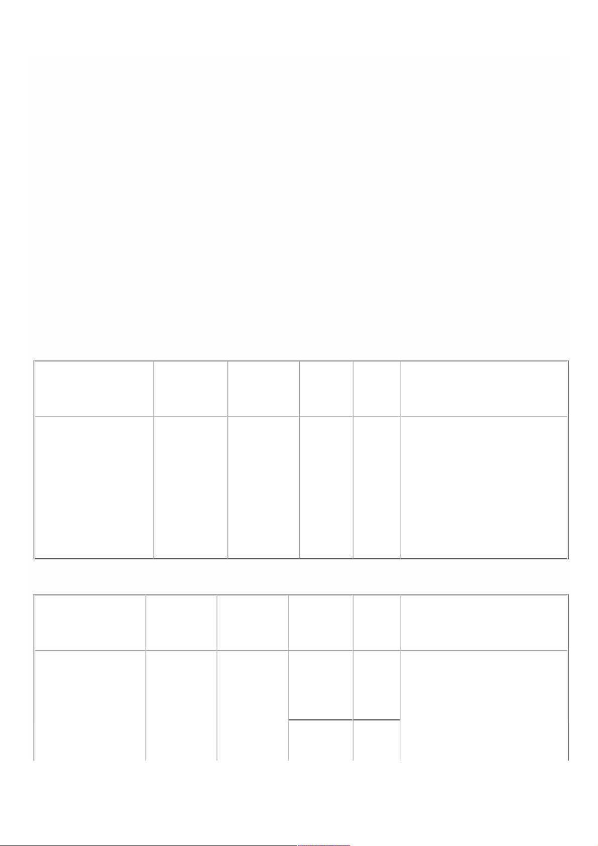
Not e: NetScaler SDX 22040/22060/22080/22100/22120 and SDX 24100/24150 appliances are shipped with f our SSDs,
which contain pre-installed configurations of the Net Scaler software. From the left, the first and second SSDs are mirrored
and store the configurations of t he SDX appliance. The third and fourth SSDs, which are also mirrored, provide storage f or
the Net Scaler instances running on the SDX appliance. All the SSDs are hot-swappable.
You can purchase up to f our additional SSDs, in groups of two.
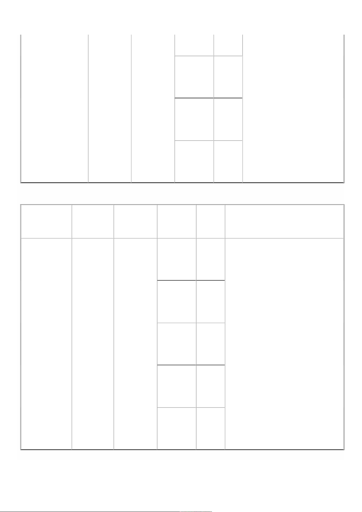
1. Locat e the SSD on t he back panel of t he appliance. Push the safet y latch of t he drive cover down while pulling out on
the drive handle to disengage. Pull out t he f aulty drive.
Figure 5. Removing the Existing Solid-Stat e Drive
© 1999-2017 Citrix Systems, Inc. All rights reserved. p.18https://docs.citrix.com
Page 16
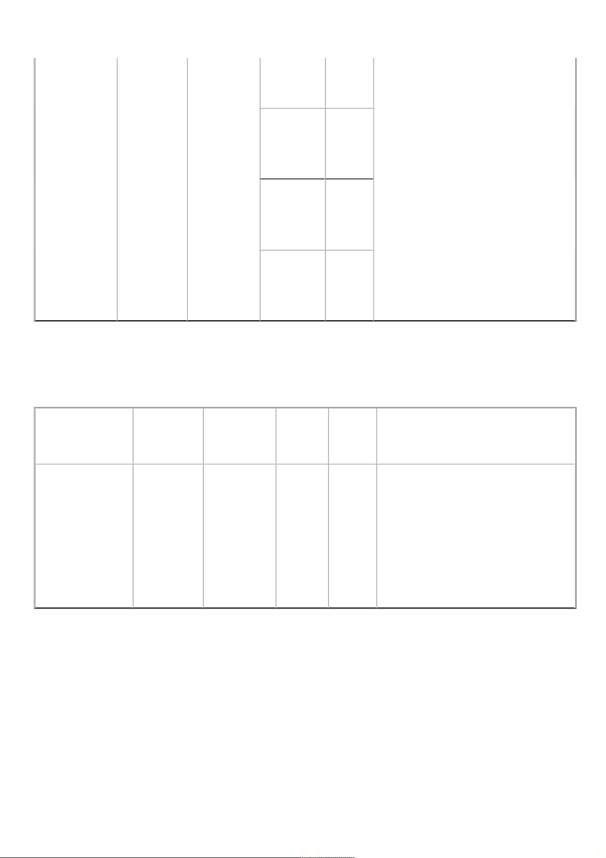
2. Verify that the replacement SSD is of t he correct type f or the platform.
3. Pick up the new SSD, open the drive handle f ully up, and insert the drive into the slot as far as possible. To seat the drive,
close the handle f lush with the rear of t he appliance so that t he drive locks securely into the slot.
Important: When you insert the drive, make sure that the Citrix product label is at t he right.
Figure 6. Inserting the Replacement Solid-State Drive
After you replace one of the SSDs, the configuration on the ot her SSD in the mirrored SSD is copied to the replacement
SSD.
Not e: NetScaler SDX 22040/22060/22080/22100/22120 and SDX 24100/24150 appliances support up to 80 instances.
However, the mirrored SSDs in the t hird and fourth slots provide only enough st orage for up to a maximum of 30
instances. To provision more instances on the appliance, you must purchase and install additional SSDs.
To a dd a ddit ional S S Ds on To add a ddit ional SS Ds o n S DX 2 2 04 0/22060/ 2 2 0 8 0 / 22100/22120 a nd S DX 24 100/24 150 appliancesSDX 2204 0/22060/ 2 2 0 8 0 / 22 100/22120 a nd S DX 2 4 100/ 2 4 150 applia nces
Put the first new SSD into t he lef tmost empty slot, and put the second new SSD into t he adjacent empty slot.
To repla c e a s o lid-st at e To repla c e a s o lid-st at e drive on any o ther S D X a pplia ncedrive on any o ther S D X a pplia nce
Replacement solid-stat e drives (SSDs) contain a pre-installed version of the Net Scaler software and a generic configuration
file (ns.conf), but they do not contain SSL-related certificates and keys, or custom boot settings. After installing the
replacement SSD, you have to restore the configuration files and customized settings f rom backup st orage. If no backups
are available, you have to reconfigure the appliance. T he f iles to be restored might include:
/f lash/nsconf ig/ns.conf: The current conf igurat ion file.
/f lash/nsconf ig/ZebOS.conf : T he ZebOS conf igurat ion file.
/f lash/nsconf ig/license: T he licenses for the Net Scaler feat ures.
/f lash/nsconf ig/ssl: The SSL certificates and keys required for encrypting data sent to clients or servers.
© 1999-2017 Citrix Systems, Inc. All rights reserved. p.19https://docs.citrix.com
Page 17

/nsconf ig/rc.netscaler: Customer-specific boot operat ions (optional).
1. In the conf igurat ion utility of the Management Service, navigat e to Configuration > System, and in the Syst em pane,
click Shutdown Appliance.
2. Locat e the SSD on the back panel of the appliance. Push the saf ety latch of the drive cover to the right or down,
depending on the platf orm, while pulling out on t he drive handle t o disengage. Pull out the f aulty drive.
Not e: The illust ration in the f ollowing figures might not represent your actual NetScaler appliance.
Figure 7. Removing the Existing Solid-State Drive
3. Verify that the replacement SSD is the correct type f or the platform.
4. Pick up the new SSD, open the drive handle fully t o the left or up, and insert t he drive into the slot as far as possible. To
seat t he drive, close the handle f lush with the rear of the appliance so that the drive locks securely into t he slot.
Important: When you insert the drive, make sure that the Citrix product label is at t he t op if the drive is inserted
horizontally, or at the right if t he drive is inserted vertically.
Figure 8. Inserting the Replacement Solid-State Drive
5. T urn on the appliance.
6. Log on to the default IP address by using a web browser, or connect to the serial console by using a console cable, and
perform the initial configuration.
7. Upload a plat f orm license and any optional f eature licenses, including universal licenses, to the NetScaler appliance.
8. Once the correct Net Scaler soft ware version is loaded, you can restore the working configuration. Copy a previous
version of the ns.conf file t o the /nsconfig directory by using an SCP utility or by pasting the previous conf iguration into
the /nsconf ig/ns.conf file f rom the Net Scaler command prompt. To load the new ns.conf file, you must restart t he
NetScaler appliance by entering the reboot command at the NetScaler command prompt.
A hard disk drive (HDD) stores logs and other data f iles. Files stored on the HDD include the newnslog f iles, dmesg and
messages files, and any core/crash files. The HDD comes in various capacities, depending on the Citrix NetScaler platf orm.
Hard drives are used for storing files required at runtime. An HDD is mounted as /var.
Replacing a Hard Disk Drive
© 1999-2017 Citrix Systems, Inc. All rights reserved. p.20https://docs.citrix.com
Page 18

A hard disk drive (HDD) stores log files and other user files. Collection of new log files begins upon boot-up with the new
HDD. Product documentat ion can be downloaded from "MyCitrix.com" and reinstalled to the /var/netscaler/doc location.
T o inst all a To inst all a hard dis k driveha rd disk drive
1. Shut down the appliance.
2. Locat e the hard disk drive on the back panel of t he appliance.
3. Verify that the replacement hard disk drive is the correct t ype for the NetScaler platform.
4. Disengage t he hard disk drive by pushing the safety latch of the drive cover to t he right or down, depending on the
plat f orm, while pulling out on t he drive handle t o disengage. Pull out t he f aulty drive.
Not e: The illust ration in the f ollowing figures might not represent t he actual NetScaler appliance.
Figure 9. Removing the Existing Hard Disk Drive
5. Pick up the new disk drive, open the drive handle f ully to the left, and insert the new drive into t he slot as far as possible.
To seat t he drive, close the handle flush with the rear of t he appliance so that t he hard drive locks securely into t he slot .
Important: When you insert the drive, make sure that the Citrix product label is at t he t op.
Figure 10. Inserting the Replacement Hard Disk Drive
6. T urn on the NetScaler appliance.
A direct attach cable (DAC) assembly is a high performance integrated duplex data link for bi-directional communication.
The cable is compliant with the IPF MSA (SFF-8432) for mechanical form factor and SFP+ MSA for direct attach cables.
The cable, which can be up to 5 met ers long, is dat a-rate agnostic. Supporting speeds in excess of 10 Gbps, it is a cost-
eff ective alternative to optical links (SFP+ transceivers and fiber optic cables.) The transceiver with DAC is hot-swappable.
You can insert and remove the transceiver with the attached cable without shutting down the appliance. The Citrix
NetScaler appliance supports only passive DAC.
Not e: Autonegot iation is not supported on an interface to which a direct attach cable (DAC) is connected.
Important:
DAC is supported only on 10G ports. Do not insert a DAC into a 1G port.
Do not attempt to unplug the integrated copper cable from the transceiver and insert a f iber cable into t he t ransceiver.
Installing a Direct Attach Cable
© 1999-2017 Citrix Systems, Inc. All rights reserved. p.21https://docs.citrix.com
Page 19

Not e: The illust rations in the f ollowing figures are only for reference and might not represent the actual NetScaler
appliance.
To inst all or remove a To inst all or remove a dire c t a tt ach cabledire c t a t tac h cable
1. To install the DAC, slide it into t he 10G port on the appliance, as shown in the f ollowing figure. You will hear a click when
the DAC properly f its into t he port.
Figure 11. Inserting a DAC into t he 10G port
2. T o remove t he DAC, pull the tab on the t op of the DAC, and then pull the DAC out of the port, as shown in the
following figure.
Figure 12. Removing a DAC f rom the 10G port
© 1999-2017 Citrix Systems, Inc. All rights reserved. p.22https://docs.citrix.com
Page 20

Hardware Platforms
Oct 0 7, 20 13
The various NetScaler hardware platforms offer a wide range of feat ures, communicat ion ports, and processing capacities.
All plat f orms have multicore processors.
The Citrix NetScaler SDX appliance is a multi-tenant plat f orm on which you can provision and manage multiple virtual
instances of NetScaler.
For information on the sof t ware releases supported on the NetScaler hardware platf orms, see NetScaler SDX Hardware
and Component Compatibility Matrix.
© 1999-2017 Citrix Systems, Inc. All rights reserved. p.23https://docs.citrix.com
Page 21

Citrix NetScaler SDX 8015, SDX 8400, and SDX 8600
Aug 0 1, 20 17
The Citrix NetScaler models SDX 8015, SDX 8400, and SDX 8600 are 1U appliances. Each model has one quad-core
processor (8 cores with hyper-threading) and 32 gigabytes (GB) of memory. The SDX 8015/8400/8600 appliances are
available in two port configurations:
Six 10/100/1000Base-T copper Ethernet ports and six 1G SFP ports (6x10/100/1000Base-T copper Ethernet ports + 6x1G
SFP)
Six 10/100/1000Base-T copper Ethernet ports and two 10G SFP+ ports (6x10/100/1000Base-T copper Ethernet ports +
2x10G SFP+)
The following figure shows the front panel of t he SDX 8015/8400/8600 (6x10/100/1000Base-T copper Ethernet ports +
6x1G SFP) appliance.
Figure 1. Citrix NetScaler SDX 8015/8400/8600 (6x10/100/1000Base-T copper Ethernet ports + 6x1G SFP), front panel
The following figure shows the front panel of t he SDX 8015/8400/8600 (6x10/100/1000Base-T copper Ethernet ports +
2x10G SFP+) appliance.
Figure 2. Citrix NetScaler SDX 8015/84 00/8600 (6x10/100/1000Base-T copper Ethernet ports + 2x10G SFP+), front panel
Depending on the model, the appliance has the following ports:
RS232 serial console port.
One 10/100Base-T copper Ethernet Port (RJ45), also called LOM port. You can use t his port to remotely monitor and
manage t he appliance independently of the NetScaler software.
One 10/100/1000Base-T copper Ethernet management port (RJ45), numbered 0/1. The management port is used to
connect directly to the appliance f or system administration functions.
Network Ports
SDX 8015/8400/8600 (6x10/100/1000Base-T copper Ethernet ports + 6x1G SFP). Six 10/100/1000BASE-T copper
© 1999-2017 Citrix Systems, Inc. All rights reserved. p.24https://docs.citrix.com
Page 22
Ethernet ports (RJ45) numbered 1/1, 1/2, 1/3, 1/4, 1/5, and 1/6 on the top row from left t o right, and six 1-gigabit
copper or fiber 1G SFP ports numbered 1/7, 1/8, 1/9, 1/10, 1/11, and 1/12 on the bottom row from left to right.
SDX 8015/8400/8600 (6x10/100/1000Base-T copper Ethernet ports + 2x10G SFP+). Six 10/100/1000BASE-T copper
Ethernet ports (RJ45) numbered 1/1, 1/2, 1/3, 1/4, 1/5, and 1/6 on the top row from left t o right and two 10-gigabit
SFP+ ports numbered 10/1 and 10/2 on the bottom row from left to right.
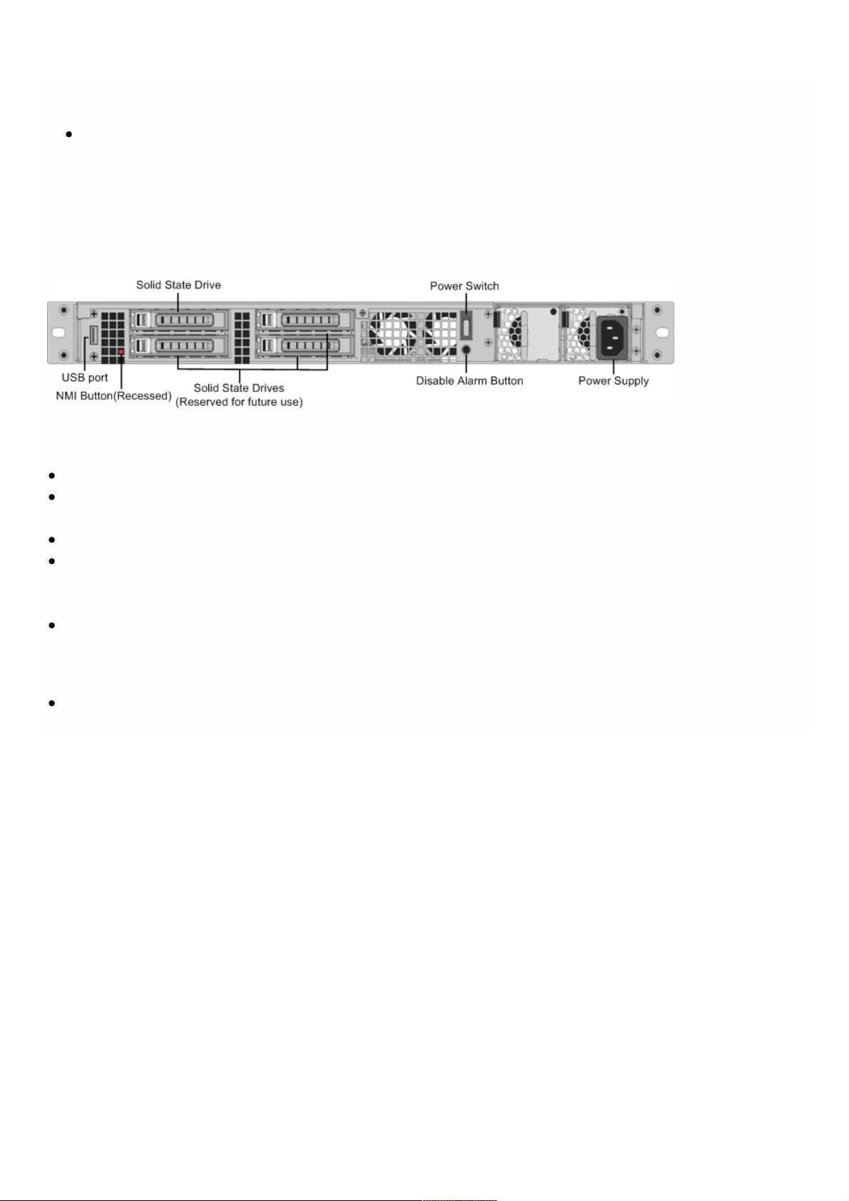
The following figure shows the back panel of the SDX 8015/8400/8600 appliance.
Figure 3. Citrix NetScaler SDX 8015/84 00/8600 appliance, back panel
The following components are visible on the back panel of t he SDX 8015/8400/8600 appliance:
300 GB removable solid-stat e drive, which is used to store the Net Scaler software and the user data.
Power switch, which turns off power to the appliance, just as if you were to unplug the power supply. Press the switch
for five seconds to turn off the power.
USB port (reserved f or a future release).
Non-maskable interrupt (NMI) butt on, which is used at t he request of T echnical Support to produce a NetScaler core
dump. You must use a pen, pencil, or other pointed object to press this red butt on, which is recessed to prevent
unintentional activation.
Disable alarm button, which is nonfunctional. T his butt on is f unctional only if you install a second power supply.
Press this button t o stop the power alarm from sounding when you have plugged the appliance into only one power
outlet or when one power supply is malfunctioning and you want to continue operating the appliance until it is repaired.
Single power supply, rated at 450 watts, 110-220 volts.
© 1999-2017 Citrix Systems, Inc. All rights reserved. p.25https://docs.citrix.com
Page 23

Citrix NetScaler SDX 11500, SDX 13500, SDX 14500,
SDX 16500, SDX 18500, and SDX 20500
Oct 25, 20 13
The Citrix NetScaler models SDX 11500/13500/14500/16500/18500/20500 are 2U appliances. Each model has two 6-core
processors for a total of 12 physical cores (24 cores with hyper-threading), and 48 gigabyt es (GB) of memory.
The following figure shows the front panel of t he SDX 11500/13500/14500/16500/18500/20500 appliance.
Figure 1. Citrix NetScaler SDX 11500/13500/14500/16500/18500/20500 appliance, front panel
The SDX 11500/13500/14500/16500/18500/20500 appliances have t he f ollowing ports:
10/100Base-T copper Ethernet Port (RJ45), also called LOM port. You can use this port to remotely monitor and manage
the appliance independently of the Net Scaler software.
Not e: The LEDs on the LOM port are not operational by design.
RS232 serial console port.
Two 10/100/1000Base-T copper Ethernet management ports (RJ45), numbered 0/1 and 0/2 f rom lef t t o right. T hese
ports are used to connect directly to the appliance f or system administration functions.
Eight 1G SFP ports numbered 1/1, 1/2, 1/3, 1/4 from top to bottom in the first column, and 1/5, 1/6, 1/7, and 1/8 from
top to bottom in the second column.
Four 10GE SFP+ ports numbered 10/1 and 10/2 from top to bot t om in the f irst column, and 10/3 and 10/4 from top to
bottom in the second column.
The following figure shows the back panel of the SDX 11500/13500/14500/16500/18500/20500 appliance.
Figure 2. Citrix NetScaler SDX 11500/13500/14500/16500/18500/20500 appliance, back panel
© 1999-2017 Citrix Systems, Inc. All rights reserved. p.26https://docs.citrix.com
Page 24

The following components are visible on the back panel of t he SDX 11500/13500/14500/16500/18500/20500 appliance:
160 GB removable solid-state drive that is used to store t he NetScaler software.
USB port (reserved f or a future release).
Power switch, which turns off power to the appliance, just as if you were to unplug the power supply. Press the switch
for five seconds to turn off the power.
Non-maskable interrupt (NMI) Button that is used at the request of T echnical Support and produces a core dump on the
NetScaler. You must use a pen, pencil, or other pointed object to press this red butt on, which is recessed to prevent
unintentional activation.
Two removable hard-disk drives that are used to store user data.
Disable alarm button. This button is functional only when the appliance has two power supplies.
Press this button t o stop the power alarm from sounding when you have plugged the appliance into only one power
outlet or when one power supply is malfunctioning and you want to continue operating the appliance until it is repaired.
Dual power supplies, each rated at 650 wat t s, 110-220 volts.
© 1999-2017 Citrix Systems, Inc. All rights reserved. p.27https://docs.citrix.com
Page 25

Citrix NetScaler SDX 11515, SDX 11520, SDX 11530,
SDX 11540, and SDX 11542
Mar 14 , 20 14
The Citrix NetScaler models SDX 11515/11520/11530/11540/11542 are 2U appliances. Each model has t wo 6-core
processors for a total of 12 physical cores (24 cores with hyper-threading), and 48 gigabyt es (GB) of memory.
The following figure shows the front panel of t he SDX 11515/11520/11530/11540/11542 appliance.
Figure 1. Citrix NetScaler SDX 11515/11520/11530/11540/11542 appliance, front panel
The SDX 11515/11520/11530/11540/11542 appliances have the following ports:
RS232 serial console port.
10/100Base-T copper Ethernet Port (RJ45), also called LOM port. You can use this port to remotely monitor and manage
the appliance independently of the Net Scaler software.
Not e: The LEDs on the LOM port are not operational by design.
Two 10/100/1000Base-T copper Ethernet management ports (RJ45), numbered 0/1 and 0/2 f rom lef t t o right. T hese
ports are used to connect directly to the appliance f or system administration functions.
Eight 10G SFP+ ports and four copper or fiber 1G SFP ports.
The following figure shows the back panel of the SDX 11515/11520/11530/11540/11542 appliance.
Figure 2. Citrix NetScaler SDX11515/11520/11530/11540/11542 appliance, back panel
© 1999-2017 Citrix Systems, Inc. All rights reserved. p.28https://docs.citrix.com
Page 26

The following components are visible on the back panel of t he SDX 11515/11520/11530/11540/11542 appliance:
256 GB removable solid-stat e drive that is used to st ore the NetScaler software.
USB port (reserved f or a future release).
Power switch, which turns off power to the appliance, just as if you were to unplug the power supply. Press the switch
for five seconds to turn off the power.
Non-maskable interrupt (NMI) Button that is used at the request of T echnical Support and produces a core dump on the
NetScaler. You must use a pen, pencil, or other pointed object to press this red butt on, which is recessed to prevent
unintentional activation.
Two removable hard-disk drives that are used to store user data.
Disable alarm button. This button is functional only when the appliance has two power supplies.
Press this button t o stop the power alarm from sounding when you have plugged the appliance into only one power
outlet or when one power supply is malfunctioning and you want to continue operating the appliance until it is repaired.
Dual power supplies, each rated at 650 wat t s, 110-220 volts.
© 1999-2017 Citrix Systems, Inc. All rights reserved. p.29https://docs.citrix.com
Page 27

Citrix NetScaler SDX 17500, SDX 19500, and SDX
21500
Oct 25, 20 13
The Citrix NetScaler models SDX 17500/19500/21500 are 2U appliances. Each model has two 6-core processors and 48
gigabytes (GB) of memory.
The following figure shows the front panel of t he SDX 17500/19500/21500 appliance.
Figure 1. Citrix NetScaler SDX 17500/19500/21500 appliance, front panel
The SDX 17500/19500/21500 appliances have the following ports:
RS232 serial console port.
Two 10/100/1000Base-T copper Ethernet management ports (RJ45), numbered 0/1 and 0/2 f rom lef t t o right. T hese
ports are used to connect directly to the appliance f or system administration functions.
Eight 10GE SFP+ ports numbered 10/1, 10/2, 10/3, and 10/4 on the top row from left t o right, and 10/5, 10/6, 10/7, and
10/8 on the bottom row from left t o right.
The following figure shows the back panel of the SDX 17500/19500/21500 appliance.
Figure 2. Citrix NetScaler SDX 17500/19500/21500 appliance, back panel
The following components are visible on the back panel of t he SDX 17500/19500/21500 appliance:
160 GB removable solid-state drive that is used to store t he NetScaler software.
USB port (reserved f or a future release).
Power switch, which turns off power to the appliance, just as if you were to unplug the power supply. Press the switch
for five seconds to turn off the power.
Non-maskable interrupt (NMI) butt on that is used at t he request of Technical Support and produces a core dump on the
NetScaler. You must use a pen, pencil, or other pointed object to press this red butt on, which is recessed to prevent
unintentional activation.
© 1999-2017 Citrix Systems, Inc. All rights reserved. p.30https://docs.citrix.com
Page 28

Removable hard-disk drive that stores user data.
Disable alarm button. This button is functional only when the appliance has two power supplies.
Press this button t o stop the power alarm from sounding when you have plugged the appliance into only one power
outlet or when one power supply is malfunctioning and you want to continue operating the appliance until it is repaired.
Dual power supplies, each rated at 650 wat t s, 110-220 volts.
© 1999-2017 Citrix Systems, Inc. All rights reserved. p.31https://docs.citrix.com
Page 29

Citrix NetScaler SDX 17550, SDX 19550, SDX 20550,
and SDX 21550
Oct 25, 20 13
The Citrix NetScaler models SDX 17550, SDX 19550, SDX 20550, and SDX 21550 are 2U appliances. Each model has two 6-
core processors f or a total of 12 physical cores (24 cores with hyper-threading), and 96 gigabytes (GB) of memory.
The following figure shows the front panel of t he SDX 17550/19550/20550/21550 appliance.
Figure 1. Citrix NetScaler SDX 17550/19550/20550/21550 appliance, front panel
The SDX 17550/19550/20550/21550 appliance has the f ollowing ports:
10/100Base-T copper Ethernet Port (RJ45), also called LOM port. You can use this port to remotely monitor and manage
the appliance independently of the Net Scaler software.
Not e: The LEDs on the LOM port are not operational by design.
RS232 serial console port.
Two 10/100/1000Base-T copper Ethernet management ports (RJ45), numbered 0/1 and 0/2 f rom lef t t o right. T hese
ports are used to connect directly to the appliance f or system administration functions.
Eight 10GE SFP+ ports numbered 10/1, 10/2, 10/3, and 10/4 on the top row from left t o right, and 10/5, 10/6, 10/7, and
10/8 on the bottom row from left t o right.
The following figure shows the back panel of the SDX 17550/19550/20550/21550 appliance.
Figure 2. Citrix NetScaler SDX 17550/19550/20550/21550 appliance, back panel
The following components are visible on the back panel of t he SDX 17550/19550/20550/21550 appliance:
160 GB removable solid-state drive that is used to store t he NetScaler software.
USB port (reserved f or a future release).
Power switch, which turns off power to the appliance, just as if you were to unplug the power supply. Press the switch
for five seconds to turn off the power.
Non-maskable interrupt (NMI) butt on that is used at t he request of Technical Support and produces a core dump on the
© 1999-2017 Citrix Systems, Inc. All rights reserved. p.32https://docs.citrix.com
Page 30

NetScaler. You must use a pen, pencil, or other pointed object to press this red butt on, which is recessed to prevent
unintentional activation.
Two removable hard-disk drives that st ore user data.
Disable alarm button. This button is functional only when the appliance has two power supplies.
Press this button t o stop the power alarm from sounding when you have plugged the appliance into only one power
outlet or when one power supply is malfunctioning and you want to continue operating the appliance until it is repaired.
Dual power supplies, each rated at 850 wat t s, 110-220 volts.
© 1999-2017 Citrix Systems, Inc. All rights reserved. p.33https://docs.citrix.com
Page 31

Citrix NetScaler SDX 22040, SDX 22060, SDX 22080,
SDX 22100, and SDX 22120
Oct 25, 20 13
The Citrix NetScaler SDX 22040/22060/22080/22100/22120 are 2U appliances. Each model has two 8-core processors (32
cores with hyper-threading) and 256 gigabytes (GB) of memory. The SDX 22040/22060/22080/22100/22120 appliances are
available in two port configurations:
Twelve 1G SFP ports and twenty-f our 10G SFP+ ports (12x1G SFP + 24x10G SFP+)
Twenty-four 10G SFP+ ports (24x10G SFP+)
The following figure shows the front panel of t he SDX 22040/22060/22080/22100/22120 (12x1G SFP + 24x10G SFP+)
appliance.
Figure 1. Citrix NetScaler SDX 22040/22060/22080/22100/22120 (12x1G SFP + 24x10G SFP+), front panel
The following figure shows the front panel of t he SDX 22040/22060/22080/22100/22120 (24x10G SFP+) appliance.
Figure 2. Citrix NetScaler SDX 2204 0/22060/22080/22100/22120 (24x10G SFP+), front panel
Depending on the model, the appliance has the following ports:
RS232 serial Console Port.
10/100Base-T copper Ethernet Port (RJ45), also called the LOM port. You can use this port to remotely monitor and
manage t he appliance independently of the NetScaler software.
Two 10/100/1000Base-T copper Ethernet Management Ports (RJ45), numbered 0/1 and 0/2 f rom lef t to right. These
ports are used to connect directly to the appliance f or system administration functions.
© 1999-2017 Citrix Systems, Inc. All rights reserved. p.34https://docs.citrix.com
Page 32

Network Ports
SDX 22040/22060/22080/22100/22120 (12x1G SFP + 24x10G SFP+). Twelve copper or fiber 1G SFP ports and
twenty-f our 10G SFP+ ports.
SDX 22040/22060/22080/22100/22120 (24x10G SFP+). Twenty-f our 10G SFP+ ports.
The following figure shows the back panel of the SDX 2204 0/22060/22080/22100/22120 appliances.
Figure 3. Citrix NetScaler SDX 2204 0/22060/22080/22100/22120, back panel
The following components are visible on the back panel of t he SDX 22040/22060/22080/22100/22120 appliance:
Non-maskable interrupt (NMI) Button, used at the request of T echnical Support to initiate a core dump. To press this red
button, which is recessed to prevent unintentional activation, use a pen, pencil, or other pointed object. The NMI Button
is also available remotely over the network in the LOM GUI, in the Remot e Control menu.
System stat us LED, which indicates the st atus of t he appliance, as described in
htt p://support.citrix.com/proddocs/topic/netscaler-hrdwre-installation-10-5/ns-hardware-common-components-
ref.html.
Not e: On an SDX 22040/22060/22080/22100/22120 appliance running LOM f irmware version 3.22, the syst em st atus
LED indicat es an error (continuously glows RED) even though the appliance is functioning properly.
Four power supplies, each rated at 750 watts, 100-240 volts. A minimum of two power supplies are required for proper
operation. T he extra power supplies act as backup. Each power supply has an LED that indicat es the status of the
power supply, as described in http://support.citrix.com/proddocs/topic/netscaler-hrdwre-installation-10-5/ns-hardware-
common-components-ref.html.
Power switch, which turns off power to the appliance. Press t he switch for less than two seconds to t urn off the
power.
256 GB removable solid-stat e drives.
© 1999-2017 Citrix Systems, Inc. All rights reserved. p.35https://docs.citrix.com
Page 33

Citrix NetScaler SDX 24100 and SDX 24150
Oct 25, 20 13
The Citrix NetScaler SDX 24 100/24150 are 2U appliances. Each model has t wo 8-core processors (32 cores with hyper-
threading) and 256 gigabytes (GB) of memory. The SDX 24100/24150 appliances are available in the twelve 1G SFP ports
and twenty-f our 10G SFP+ ports (12x1G SFP + 24x10G SFP+) configuration.
The following figure shows the front panel of t he SDX 24 100/24150 (12x1G SFP + 24x10G SFP+ ) appliance.
Figure 1. Citrix NetScaler SDX 24 100/24150 (12x1G SFP + 24x10G SFP+ ), front panel
Depending on the model, the appliance has the following ports:
RS232 serial Console Port.
10/100Base-T copper Ethernet Port (RJ45), also called the LOM port. You can use this port to remotely monitor and
manage t he appliance independently of the NetScaler software.
Two 10/100/1000Base-T copper Ethernet Management Ports (RJ45), numbered 0/1 and 0/2 f rom lef t to right. These
ports are used to connect directly to the appliance f or system administration functions.
Network Ports
SDX 24100/24150 (12x1G SFP + 24 x10G SFP+). Twelve copper or f iber 1G SFP ports and twenty-four 10G SFP+ ports.
The following figure shows the back panel of the SDX 24100/24150 appliances.
Figure 2. Citrix NetScaler SDX 24100/24 150, back panel
© 1999-2017 Citrix Systems, Inc. All rights reserved. p.36https://docs.citrix.com
Page 34

The following components are visible on the back panel of t he SDX 24 100/24150 appliance:
Non-maskable interrupt (NMI) Button, used at the request of T echnical Support to initiate a core dump. To press this red
button, which is recessed to prevent unintentional activation, use a pen, pencil, or other pointed object. The NMI Button
is also available remotely over the network in the LOM GUI, in the Remot e Control menu.
System stat us LED, which indicates the st atus of t he appliance, as described in
htt p://support.citrix.com/proddocs/topic/netscaler-hrdwre-installation-10-5/ns-hardware-common-components-
ref.html.
Not e: On an SDX 24100/24150 appliance running LOM firmware version 3.22, the syst em status LED indicat es an error
(continuously glows RED) even though the appliance is functioning properly.
Four power supplies, each rated at 750 watts, 100-240 volts. A minimum of two power supplies are required for proper
operation. T he extra power supplies act as backup. Each power supply has an LED that indicat es the status of the
power supply, as described in http://support.citrix.com/proddocs/topic/netscaler-hrdwre-installation-10-5/ns-hardware-
common-components-ref.html.
Power switch, which turns off power to the appliance. Press t he switch for less than two seconds to t urn off the
power.
Four 600 GB removable solid-stat e drives. The first two left most solid-state drives store the NetScaler software. The
next two solid-stat e drives store user data. Additionally, you can extend the SSD storage (optional) by another 2 or 4
600 GB SSDs.
© 1999-2017 Citrix Systems, Inc. All rights reserved. p.37https://docs.citrix.com
Page 35

Citrix NetScaler SDX 14020, SDX 14030, SDX 14040,
SDX 14060, SDX 14080 and SDX 14100
Dec 22, 20 16
The Citrix NetScaler SDX 14020/14030/14040/14060/14080/14100 are 2U appliances. Each model has two 6-core processors and 64 gigabytes (GB) of memory
and sixteen 10G SFP+ ports (16x10G SFP+).
Note: For information about NetScaler SDX hardware and component compatibi lity matrix, see https://docs.citrix.com/en-us/sdx/11/sdx-ag-supported-versio ns-
ref.html.
The following figure shows the front panel of the SDX 14020/14030/14040/14060/14080/ 14100 ( 16x10G SFP+) appliance.
Figure 1. Citrix NetScaler SDX 14020 /14030/14040/14060/14080/14100 ( 16x10G SFP+), front panel
The NetScaler SDX 14020/14030/14040/14060/14080/14100 appliances have the following ports:
RS232 serial Console Port.
10/100Base-T copper Ethernet Port (RJ45), also called the LOM port. You can use this port to remotely monitor and
manage t he appliance independently of the NetScaler software.
Two 10/100/1000Base-T copper Ethernet Management Ports (RJ45), numbered 0/1 and 0/2 f rom lef t t o right. T hese
ports are used to connect directly to the appliance f or system administration functions.
Net work Ports, sixteen 10G SFP+ ports ( 16x10G SFP+ ).
Not e:Not e: The 10G SFP+ ports on these appliances support copper 1G SFP t ransceivers.
The following figure shows the back panel of the SDX 14020/14030/14040/14060/14080/ 14100 appliance.
Figure 2 . Cit rix N e t Sc a ler S D X 14 020/14 030/14 04 0/ 14 0 6 0 / 14 08 0 / 14 100, back pa nelFigure 2 . Cit rix N e t Sc a ler S D X 14 020/14 030/14 04 0/ 14 0 6 0 / 14 08 0 / 14 100, back pa nel
© 1999-2017 Citrix Systems, Inc. All rights reserved. p.38https://docs.citrix.com
Page 36

The following components are visible on the back panel of t he SDX 14020/14030/14040/14060/14080/14100 appliance:
Two 240 GB removable solid-stat e drives (SSDs). The two leftmost solid-state drives st ore the NetScaler software. The
next two solid-stat e drives, of 300 GB each, store user data. T he remaining four solid-state drives are reserved f or future
use. The Net Scaler SDX 14040 appliance has six 300 GB SSDs and Net Scaler SDX 14060/14080/14100 appliances have
eight 300 GB SSDs. These appliances are redundant array of independent disks (RAID) devices. For more information, see
htt p://docs.citrix.com/en-us/sdx/11/manage-monitor-appliance-network-configurat ion/raid-introduction.html.
Power switch, which turns power to the appliance on or off. Press t he switch f or less than two seconds to turn off the
power.
Two power supplies, each rated at 1000 wat ts, 100-240 volts. Each power supply has an LED t hat indicates the stat us of
the power supply, as described in http://docs.citrix.com/en-us/sdx/11/hardware-installation/common-hardware-
components.html.
Disable alarm button, which is functional only when the appliance has two powersupplies. Press this button to st op the
power alarm from sounding when you have plugged the appliance into only one power outlet, or when one power supply
is malfunctioning and you want to continue operating the appliance until it is repaired.
Non-maskable interrupt (NMI) Butt on, used at t he request of Technical Support to initiate a core dump. To press this
red button, which is recessed to prevent unintentional activation, use a pen, pencil, or ot her pointed object. T he NMI
Butt on is also available remotely over the network in the LOM GUI, in the Remote Control menu. For more information
about the lights out management port of t he appliance, see http://docs.citrix.com/en-us/sdx/11/hardware-
installation/lights-out-management-port-lom-of-sdx.html.
© 1999-2017 Citrix Systems, Inc. All rights reserved. p.39https://docs.citrix.com
Page 37

Citrix NetScaler SDX 14020 40G, SDX 14040 40G, SDX
14060 40G, SDX 14080 40G, SDX 14100 40G
Mar 24 , 20 16
The Citrix NetScaler SDX 14020 40G, SDX 14040 4 0G, SDX 14060 40G, SDX 14080 4 0G, and SDX 14100 40G are 2U
appliances. Each model has two 6-core processors and 64 gigabytes (GB) of memory. The SDX 14020 40G, 1404 0 40G, SDX
14060 4 0G, SDX 14080 40G, and SDX 14100 40G appliances are available in the four 40G QSFP+ ports and sixteen 10G
SFP+ ports (4x40G QSFP+ + 16x10G SFP+ ) configurat ion.
The following figure shows the front panel of t he SDX 14020 40G, SDX 14040 4 0G, SDX 14060 40G, SDX 14080 4 0G
(4x4 0G QSFP+ + 16x10G SFP+) appliance.
Figure 1. Citrix NetScaler SDX 14020 40G, SDX 14040 4 0G, SDX 14060 40G, SDX 14080 40G (4x4 0G QSFP+ + 16x10G SFP+),
front panel
The NetScaler SDX 14020 40G, SDX 14040 40G, SDX 14060 4 0G, SDX 14080 40G appliances have t he following ports:
RS232 serial Console Port.
10/100Base-T copper Ethernet Port (RJ45), also called the LOM port. You can usethis port to remotely monitor and
manage t he appliance independently of the NetScaler software.
Two 10/100/1000Base-T copper Ethernet Management Ports (RJ45), numbered 0/1and 0/2 from lef t t o right. T hese
ports are used to connect directly to the appliancef or system administration functions.
Network Ports, four 40G QSFP+ ports and sixteen 10G SFP+ ports (4x40G QSFP+ + 16x10G SFP+).
Not e the following points regarding the network ports on SDX 14020 40G, SDX 1404 0 40G, SDX 14060 40G, SDX
14080 4 0G appliances:
o 10G ports do not support 1G copper or 1G fiber transceivers.
o 40G ports do not support 10G and 1G transceivers.
The following figure shows the back panel of the SDX 14020 40G, SDX 14040 40G, SDX 14060 40G, SDX 14080 40G
© 1999-2017 Citrix Systems, Inc. All rights reserved. p.40https://docs.citrix.com
Page 38

appliance.
Figure 2. Citrix NetScaler SDX 14020 40G, SDX 14040 40G, SDX 14060 40G, SDX 14080 40G, back panel
The following components are visible on the back panel of t he SDX 14020 40G, SDX 14040 4 0G, SDX 14060 40G, SDX
14080 4 0G appliance:
Two 240 GB removable solid-stat e drives (SSDs). The two leftmost solid-state drives st ore the NetScaler software. The
next two solid-stat e drives store user data. The remaining four solid-state drives are reserved for future use.These
appliances are redundant array of independent disks (RAID) devices. In a RAID configuration, the same data is stored on
multiple drives to improve perf ormance, increase st orage capacity, lower the risk of data loss, and provide fault t olerance.
T he two SSDs store the same dat a. If one fails and you replace it, the new SSD mirrors the ot her one.
Power switch, which turns power to the appliance on or off. Press t he switch f or lesst han two seconds to turn off the
power.
Two power supplies, each rated at 1000 wat ts, 100-240 volts. Each power supply hasan LED t hat indicates the status of
the power supply, as described in http://docs.citrix.com/en-us/netscaler/10-1/ns-gen-hardware-wrapper-10-con/ns-
hardware-common-components-ref .html.
Disable alarm button, which is functional only when the appliance has two powersupplies.
Press this button t o stop the power alarm from sounding when you have plugged the appliance into only one power
outlet, or when one power supply is malfunctioning and you want to continue operating the appliance until it is
repaired.
Non-maskable interrupt (NMI) Button, used at the request of T echnical Support toinitiate a core dump. To press this red
button, which is recessed to preventunintentional activation, use a pen, pencil, or ot her pointed object . The NMI Button
is also available remotely over the network in the LOM GUI, in the Remot e Control menu. For more inf ormation about
the lights out management port of the appliance, see http://docs.citrix.com/en-us/netscaler/10-1/ns-gen-hardware-
wrapper-10-con/ns-hardware-lom-intro-wrapper-con.html.
© 1999-2017 Citrix Systems, Inc. All rights reserved. p.41https://docs.citrix.com
Page 39

Citrix NetScaler SDX 25100-40G, SDX 25160-40G
Mar 24 , 20 16
The Citrix NetScaler SDX 25100-40G, SDX 25160-40G are 2U appliances. Each model has two 10-core processors, 256
gigabytes (GB) of memory, four 40G QSFP+ ports, and sixteen 10G SFP+ ports (4x40G QSFP+ + 16x10G SFP+).
The following figure shows the front panel of t he SDX 25100-40G, SDX 25160-40G (4x4 0G QSFP+ + 16x10G SFP+)
appliance.
Figure 1Figure 1. Citrix NetScaler SDX 25100-40G, SDX 25160-40G (4x40G QSFP+ + 16x10G SFP+), front panel
The NetScaler SDX 25100 40G, SDX 25160 40G appliances have the following ports:
RS232 serial Console Port.
10/100Base-T copper Ethernet Port (RJ45), also called the LOM port. You can usethis port to remotely monitor and
manage t he appliance independently of the NetScaler software.
Two 10/100/1000Base-T copper Ethernet Management Ports (RJ45), numbered 0/1and 0/2 from lef t t o right. T hese
ports are used to connect directly to the appliancef or system administration functions.
Network Ports, four 40G QSFP+ ports and sixteen 10G SFP+ ports (4x40G QSFP+ + 16x10G SFP+).
Not e the following points regarding the network ports on SDX 25100-40G, SDX 25160-40G appliances:
o 10G ports do not support 1G copper or 1G fiber transceivers.
o 40G ports do not support 10G and 1G transceivers.
The following figure shows the back panel of the SDX 25100-40G, SDX 25160-40G appliance.
Figure 2Figure 2 . Citrix NetScaler SDX 25100-40G and SDX 25160-40G back panel
© 1999-2017 Citrix Systems, Inc. All rights reserved. p.42https://docs.citrix.com
Page 40

The following components are visible on the back panel of t he SDX 25100-40G, SDX 25160-40G appliance:
Two 300 GB removable solid-stat e drives (SSDs). The two leftmost solid-state drives store t he NetScaler software. The
next two solid-stat e drives, of 300 GB each, store user data. T he remaining four solid-state drives are reserved f or future
use. These appliances are redundant array of independent disks (RAID) devices. For more information, see
htt p://docs.citrix.com/en-us/sdx/11/manage-monitor-appliance-network-configurat ion/raid-introduction.html.
Power switch, which turns power to the appliance on or off. Press t he switch f or less than two seconds to turn off the
power.
Two power supplies, each rated at 1000 wat ts, 100-240 volts. Each power supply has an LED t hat indicates the stat us of
the power supply, as described in http://docs.citrix.com/en-us/sdx/11/hardware-installation/common-hardware-
components.html.
Disable alarm button, which is functional only when the appliance has two powersupplies.
Press this button t o stop the power alarm from sounding when you have plugged the appliance into only one power
outlet, or when one power supply is malfunctioning and you want to continue operating the appliance until it is
repaired.
Non-maskable interrupt (NMI) Button, used at the request of T echnical Support to initiate a core dump. To press this red
button, which is recessed to preventunintentional activation, use a pen, pencil, or ot her pointed object . The NMI
Butt onis also available remotely over the network in the LOM GUI, in the Remote Controlmenu. For more information
about the lights out management port of t he appliance, see http://docs.citrix.com/en-us/sdx/11/hardware-
installation/lights-out-management-port-lom-of-sdx.html.
© 1999-2017 Citrix Systems, Inc. All rights reserved. p.43https://docs.citrix.com
Page 41

Citrix NetScaler SDX 25100A, SDX 25160A
Jan 11, 20 17
The Citrix NetScaler SDX 25100A and SDX 25160A are 2U appliances. Each model has two 10-core processors, 256 GB of
memory, eight 4 0GE QSFP+ ports (8x40GE QSFP+).
The following figure shows the front panel of t he SDX 25100A and SDX 25160A appliance.
Figure 1Figure 1. Citrix NetScaler SDXSDX 25100A and SDX 25160A (8x40GE QSFP+) front panel
The NetScaler SDX 25160A and SDX 25100A appliances have the following ports:
RS232 serial Console Port.
10/100Base-T copper Ethernet Port (RJ45), also called the LOM port. You can use this port to remotely monitor and
manage t he appliance independently of the NetScaler software.
Two 10/100/1000Base-T copper Ethernet Management Ports (RJ45), numbered 0/1and 0/2 from lef t t o right. T hese
ports are used to connect directly to the appliancef or system administration functions.
Network ports, eight 40GE QSFP+ ports (8x40GE QSFP+ ).
Not e the following points regarding the network ports on SDX 25100A and SDX 25160A appliances:
10GE ports do not support 1G copper or 1G fiber transceivers.
40GE ports do not support 10G and 1G transceivers.
The following figure shows the back panel of the SDX SDX 25100A and SDX 25160A appliance.
Figure 2Figure 2 . Citrix NetScaler SSDX 25100A and SDX 25160A back panel
© 1999-2017 Citrix Systems, Inc. All rights reserved. p.44https://docs.citrix.com
Page 42

The following components are visible on the back panel of t he SDX 25100A and SDX 25160A appliance:
Two 300 GB removable solid-stat e drives (SSDs). The two leftmost solid-state drives store t he NetScaler software. The
next two solid-stat e drives, of 300 GB each, store user data. T he remaining four solid-state drives are reserved f or future
use. These appliances are redundant array of independent disks (RAID) devices. For more information,
see http://docs.citrix.com/en-us/sdx/11/manage-monitor-appliance-network-configuration/raid-introduction.html.
Power switch, which turns power to the appliance on or off. Press t he switch f or less than two seconds to turn off the
power.
Two power supplies, each rated at 1000 wat ts, 100-240 volts. Each power supply has an LED t hat indicates the stat us of
the power supply, as described in http://docs.citrix.com/en-us/sdx/11/hardware-installation/common-hardware-
components.html.
Disable alarm button, which is functional only when the appliance has two powersupplies.
Press this button t o stop the power alarm from sounding when you have plugged the appliance into only one power outlet,
or when one power supply is malfunctioning and you want t o continue operating the appliance until it is repaired.
Non-maskable interrupt (NMI) Button, used at the request of T echnical Support to initiate a core dump. To press this red
button, which is recessed to preventunintentional activation, use a pen, pencil, or ot her pointed object . The NMI
Butt onis also available remotely over the network in the LOM GUI, in the Remote Controlmenu. For more information
about the lights out management port of t he appliance, see http://docs.citrix.com/en-us/sdx/11/hardware-
installation/lights-out-management-port-lom-of-sdx.html.
© 1999-2017 Citrix Systems, Inc. All rights reserved. p.45https://docs.citrix.com
Page 43

Citrix NetScaler SDX 14040-40S, SDX 14060-40S, SDX
14080-40S, SDX 14100-40S
May 02, 20 17
The Citrix NetScaler SDX 14040-40S/14060-4 0S/14080-40S/14100-40S are 2U appliances. Each model has two 6-core
processors and 64 gigabyt es (GB) of memory and four 40GE QSFP+ ports and eight 10GE SFP+(4x 40GE QSFP+ ; 8x 10GE
SFP+).
Not e: For inf ormation about NetScaler SDX hardware and component compatibility matrix, see htt ps://docs.citrix.com/en-
us/sdx/11/sdx-ag-supported-versions-ref.html.
The following figure shows the front panel of t he SDX 14040-40S/14060-40S/14080-40S/14100-40S (4x 4 0GE QSFP+; 8x
10GE SFP+) appliance.
Figure 1Figure 1. Citrix NetScaler SDX 1404 0-40S/14060-40S/14080-40S/14100-40S f ront panel
The NetScaler SDX 14040-40S/14060-40S/14080-40S/14100-40S appliances have the following ports:
RS232 serial Console Port.
10/100Base-T copper Ethernet Port (RJ45), also called the LOM port. You can use this port to remotely monitor and
manage t he appliance independently of the NetScaler software.
Two 10/100/1000Base-T copper Ethernet Management Ports (RJ45), numbered 0/1 and 0/2 f rom lef t t o right. T hese
ports are used to connect directly to the appliance f or system administration functions.
Net work ports: four 40GE QSFP+ ports and eight 10GE SFP+(4x 40GE QSFP+ ; 8x 10GE SFP+).
Not e: The 10G SFP+ ports on these appliances support copper 1G SFP transceivers.
The following figure shows the back panel of the SDX 14020/14030/14040/14060/14080/ 14100 appliance.
Figure 2. Citrix NetScaler SDX 1404 0-40S/14060-40S/14080-40S/14100-40S back panel
© 1999-2017 Citrix Systems, Inc. All rights reserved. p.46https://docs.citrix.com
Page 44

The following components are visible on the back panel of t he SDX 14020/14030/14040/14060/14080/14100 appliance:
Two 240 GB removable boot solid-state drives (SSDs). The t wo leftmost solid-state drives st ore the Net Scaler soft ware.
Four 300 GB st orage SSD. The next t wo solid-state drives, of 300 GB each, store user data. The remaining four solid-
state drives are reserved for future use. These appliances are redundant array of independent disks (RAID) devices. For
more information, see htt p://docs.citrix.com/en-us/sdx/11/manage-monitor-appliance-network-configurat ion/raid-
introduction.html.
Power switch, which turns power to the appliance on or off. Press t he switch f or less than two seconds to turn off the
power.
Two power supplies, each rated at 1000 wat ts, 100-240 volts. Each power supply has an LED t hat indicates the stat us of
the power supply, as described in http://docs.citrix.com/en-us/sdx/11/hardware-installation/common-hardware-
components.html.
Disable alarm button, which is functional only when the appliance has two powersupplies. Press this button to st op the
power alarm from sounding when you have plugged the appliance into only one power outlet, or when one power supply
is malfunctioning and you want to continue operating the appliance until it is repaired.
Non-maskable interrupt (NMI) Butt on, used at t he request of Technical Support to initiate a core dump. To press this
red button, which is recessed to prevent unintentional activation, use a pen, pencil, or ot her pointed object. T he NMI
Butt on is also available remotely over the network in the LOM GUI, in the Remote Control menu. For more information
about the lights out management port of t he appliance, see http://docs.citrix.com/en-us/sdx/11/hardware-
installation/lights-out-management-port-lom-of-sdx.html.
© 1999-2017 Citrix Systems, Inc. All rights reserved. p.47https://docs.citrix.com
Page 45

Citrix NetScaler SDX 14030 FIPS, 14060 FIPS, 14080
FIPS
Jul 07, 20 17
See Configuring an SDX 14000 FIPS Appliance for more information.
© 1999-2017 Citrix Systems, Inc. All rights reserved. p.48https://docs.citrix.com
Page 46
Summary of Hardware Specifications
May 11, 20 17
The following tables summarize the specifications of the hardware plat f orms. The latest NetScaler dat asheet is available
at https://www.citrix.com/products/netscaler-adc/.
Table 1. SDX Platf orm Summary
SDX 8015/SDX
84 00/SDX 8600
SDX 11500/SDX
13500/SDX 14500/SDX
16500/SDX 18500/SDX
20500
SDX
11515/11520/11530/11540/1154 2
Processors 1 quad-core (8 cores with
hyper-threading)
2 six-core (24 cores with
hyper-threading)
2 six-core
Memory 32 GB 48 GB 48 GB
Ports - 1G 6x1G SFP +
6x10/100/1000 Base-T
copper Ethernet model:
6xcopper/fiber 1G SFP
ports,
6x10/100/1000Base-T
copper Ethernet ports
2x10G SFP+
6x10/100/1000 Base-T
copper Ethernet model:
6xcopper/fiber 1G SFP
ports,
8x1G SFP ports 8x1G SFP + 4 x10G SFP+ model:
8xcopper/fiber 1G SFP ports
8x1G SFP + 8x10/100/1000Base-
T copper Ethernet model:
8xcopper/fiber 1G SFP ports,
8x10/100/1000Base-T copper
Ethernet ports
Ports - 10G 2x10G SFP+
6x10/100/1000 Base-T
copper Ethernet model:
2x10G SFP+ Ports
4x10G SFP+ ports 8x1G SFP + 4 x10G SFP+ model:
4x10G SFP+ ports
Number of Power
Supplies
1 2 2
Maximum NetScaler 5 20 20
© 1999-2017 Citrix Systems, Inc. All rights reserved. p.49https://docs.citrix.com
Page 47

Instances
Supported
AC Power Supply
input voltage,
frequency, &
current
100–240 VAC
50– 60 Hz
2.5 A
100-240 VAC
50-60 Hz
6.5-3.5 A
100–240 VAC
50– 60 Hz
6.5– 3.5 A
Maximum Power
Consumption
450 W 650 W 650 W
Heat Dissipat ion 630 BT U per hour 2200 BT U per hour 2200 BT U per hour
Weight 32 lbs
14.52 kg
46 lbs 46 lbs
20.87 kg
Height 1U 2U 2U
Width EIA 310-D for 19-inch
racks
EIA 310-D for 19-inch racks EIA 310-D for 19-inch racks
Depth 24.01 in or 61 cm 28 in or 71.68 cm 28 in or 71.68 cm
Operating
Temperature
(degree Celsius)
0– 4 0° C
32– 104° F
0-40 0– 4 0° C
32– 104° F
Humidity range
(non-condensing)
5%– 95% 5%-95% 5%– 95%
Saf ety
Certifications
TUV CSA CSA
EMC &
Susceptibility
FCC (Part 15 Class A), CE,
C-Tick, VCCI-A
FCC (Part 15 Class A), CE, C-
Tick, VCCI, CCC, KC, NOM,
GOST, SABS, SASO
FCC (Part 15 Class A), CE, C-Tick,
VCCI, CCC, KC, NOM, GOST, SABS,
SASO
Compliance RoHS, WEEE RoHS, SVHC, WEEE RoHS, SVHC, WEEE
SDX 8015/SDX
84 00/SDX 8600
SDX 11500/SDX
13500/SDX 14500/SDX
16500/SDX 18500/SDX
20500
SDX
11515/11520/11530/11540/1154 2
© 1999-2017 Citrix Systems, Inc. All rights reserved. p.50https://docs.citrix.com
Page 48

Table 2. SDX Platf orm Summary (contd.)
SDX 17500/SDX
19500/SDX
21500
SDX 17550/SDX
19550/SDX
20550/SDX 21550
SDX 2204 0/SDX
22060/SDX 22080/SDX
22100/SDX 22120
SDX 24100/SDX
24150
Processors 2 six-core (24
cores with
hyper-threading)
2 six-core (24 cores
with hyper-
threading)
2 eight-core (32 cores
with hyper-threading )
2 eight-core (32 cores
with hyper-threading )
Memory 48 GB 96 GB 256 GB 256 GB
Ports - 1G NA NA 12x1G SFP + 24 x10G
SFP+ model:
12xcopper/fiber 1G SFP
ports
12x1G SFP + 24 x10G
SFP+ model:
12xcopper/fiber 1G
SFP ports
Ports - 10G 8x10G SFP+
ports
8x10G SFP+ ports 12x1G SFP + 24 x10G
SFP+ model:
24x10G SFP+ ports
24x10G SFP+ port s
model:
24x10G SFP+ ports
12x1G SFP + 24 x10G
SFP+ model:
24x10G SFP+ ports
Number of Power
Supplies
2 2 4 4
Maximum NetScaler
Instances Supported
20 40 80 80
AC Power Supply
input voltage,
frequency, & current
100-240 VAC
50-60 Hz
6.5-3.5 A
100-240 VAC
50-60 Hz
6.5-3.5 A
12x1G SFP + 24 x10G
SFP+ model:
100-240VAC
50/60Hz
6.0-12.0A
24x10G SFP+ model:
100-240VAC
12x1G SFP + 24 x10G
SFP+ model:
100-240VAC
50/60Hz
6.0-12.0A
50/60 hz
© 1999-2017 Citrix Systems, Inc. All rights reserved. p.51https://docs.citrix.com
Page 49

50/60Hz
6.5-15.5A
Maximum Power
Consumption
650 W 850 W 12x1G SFP + 24 x10G
SFP+ model:
1050 W
24x10G SFP+ model:
1400 W
12x1G SFP + 24 x10G
SFP+ model:
1050 W
Heat Dissipat ion 2200 BTU per
hour
2900 BT U per hour 12x1G SFP + 24 x10G
SFP+ model:
2,000-2,6000 BT U per
hour
24x10G SFP+ model:
2,700-3,800 BT U per hour
12x1G SFP + 24 x10G
SFP+ model:
2,000-2,6000 BT U per
hour
Weight 40 lbs 40 lbs 85 lbs
38.56 kg
85 lbs
38.56 kg
Height 2U 2U 2U 2U
Width EIA 310-D f or
19-inch racks
EIA 310-D for 19-
inch racks
EIA 310-D for 19-inch
racks
EIA 310-D for 19-inch
racks
Depth 24.75 in or
62.865 cm
24.75 in or 62.865
cm
28¼ in or 72 cm 28¼ in or 72 cm
Operating
Temperature (degree
Celsius)
0-40 0-40 0– 4 0° C
32– 104° F
0– 4 0° C
32– 104° F
Humidity range (non-
condensing)
5%-95% 5%-95% 20%– 80% 20%– 80%
Saf ety Certifications TUV TUV CSA CSA
SDX 17500/SDX
19500/SDX
21500
SDX 17550/SDX
19550/SDX
20550/SDX 21550
SDX 2204 0/SDX
22060/SDX 22080/SDX
22100/SDX 22120
SDX 24100/SDX
24150
© 1999-2017 Citrix Systems, Inc. All rights reserved. p.52https://docs.citrix.com
Page 50

EMC & Susceptibility FCC (Part 15
Class A), CE,
C-
Tick, VCCI-A
FCC (Part 15 Class
A), CE, C-Tick, VCCI-
A
FCC (Part 15 Class A), CE
(EN55022/55024 ), C-Tick,
VCCI
Compliance RoHS, WEEE RoHS, WEEE RoHS, WEEE RoHS, WEEE
SDX 17500/SDX
19500/SDX
21500
SDX 17550/SDX
19550/SDX
20550/SDX 21550
SDX 2204 0/SDX
22060/SDX 22080/SDX
22100/SDX 22120
FSCDCX (2P4ar1t0 105/ SClDaXss A),
Table 3. SDX Platform Summary (contd.)
Specificat ions SDX
14020/14 030/14 04 0/14 060/14 080/14 100
SDX 14020-4 0G/14 04 040G/14 06040G/14 080-4 0G/14 10040G
SDX 1404 040S/1406040S/1408040S/14100-4 0S
Regulatory model
number
Citrix 2U1P1B
Citrix 2U1P1B Citrix 2U1P1B
Processors 2 six-core
2 six-core 2 six-core
Memory 64 GB
64 GB 64 GB
Number of power
supplies
2
2 2
AC power supply
input voltage,
frequency, and
current
100-240V AC
50-60 Hz
5.9 – 2.95 A
100-240V AC
50-60 Hz
5.9 – 2.95 A
100-240V AC
50-60 Hz
5.9 – 2.95 A
DC power supply
input voltage and
current
-36V t o -72V DC
16.5 – 8.25 A
-36V t o -72V DC
16.5 – 8.25 A
-36V t o -72V DC
16.5 – 8.25 A
Maximum AC
power
consumption
528 W
528 W 528 W
Maximum DC
power
consumption
594 W
594 W 594 W
Airflow (front t o 110 CFM Typical 110 CFM Typical 110 CFM Typical
CE (EN55022/55024),
24150
C-Tick, VCCI
© 1999-2017 Citrix Systems, Inc. All rights reserved. p.53https://docs.citrix.com
Page 51

rear)
175 CFM Maximum 175 CFM Maximum 175 CFM Maximum
Heat dissipation 1412 BT U per hour Typical
1412 BTU per hour Typical
1412 BTU per hour
Typical
Package weight
(lbs.)
60
60 60
System weight
(lbs.)
39
39 39
Height 2U
2U 2U
Width EIA 310-D for 19-inch racks EIA 310-D for 19-inch
racks
EIA 310-D for 19inch racks
Depth 7 2 cm; 28¼ in
72 cm; 28¼ in 72 cm; 28¼ in
Operating
temperature
0-40°C; 32-104°F
0-40°C; 32-104°F 0-40°C; 32-104°F
Humidity range
(non-condensing)
20%-80%
20%-80% 20%-80%
Saf ety
certifications
CSA
CSA CSA
EMC &
susceptibility
USA (FCC), Europe (CE), Japan (VCCI),
Australia (RCM), China (CCC), Korea
(KCC), India (BIS), Mexico (NOM), Saudi
Arabia (CITC), South Africa (ICASA),
Russia (EAC, CU-TR), Taiwan (BSMI),
Brazil (Inmet ro & Anat el), Israel (MoE,
MoC)
USA (FCC), Europe (CE),
Japan (VCCI),
Australia (RCM), China
(CCC), Korea
(KCC), India (BIS), Mexico
(NOM), Saudi
Arabia (CITC), South Africa
(ICASA),
Russia (EAC, CU-TR),
Taiwan (BSMI),
Brazil (Inmet ro & Anat el),
Israel (MoE,
USA (FCC), Europe
(CE), Japan (VCCI),
Australia (RCM),
China (CCC), Korea
(KCC), India (BIS),
Mexico (NOM),
Saudi
Arabia (CITC), South
Africa (ICASA),
Russia (EAC, CU-TR),
Taiwan (BSMI),
Brazil (Inmet ro &
Anatel), Israel (MoE,
© 1999-2017 Citrix Systems, Inc. All rights reserved. p.54https://docs.citrix.com
Page 52

MoC) MoC)
Environmental
compliance
WEEE, RoHS, REACH
WEEE, RoHS, REACH
WEEE, RoHS,
REACH
Table 4. SDX Platform Summary (contd.)
Specifications SDX 25160A/25100A
SDX 25100-40G/25160-40G
Regulatory model number Citrix 2U1P1D
Citrix 2U1P1D
Processors 2 10-core
2 10-core
Memory 256 GB
256 GB
Number of power supplies 2
2
AC power supply input voltage,
frequency, and current
100-240V AC
50-60 Hz
5.9 – 2.95 A
100-240V AC
50-60 Hz
5.9 – 2.95 A
DC power supply input voltage and
current
-36V t o -72V DC
16.5 – 8.25 A
-36V t o -72V DC
16.5 – 8.25 A
Maximum AC power consumption 822 W
528 W
Maximum DC power consumption 594 W
594 W
Airflow (front t o rear)
Heat dissipation
Package weight (lbs.) 60
60
System weight (lbs.) 39
39
Height 2U
2U
© 1999-2017 Citrix Systems, Inc. All rights reserved. p.55https://docs.citrix.com
Page 53

Width EIA 310-D for 19-inch racks
EIA 310-D for 19-inch racks
Depth 71.2 cm; 28 in
71.2 cm; 28 in
Operating temperat ure 0-40°C; 32-104°F
0-40°C; 32-104°F
Humidity range (non-condensing) 5%-95%
5%-95%
Saf ety certifications CSA
CSA
EMC & susceptibility
Environmental compliance RoHS
RoHS
© 1999-2017 Citrix Systems, Inc. All rights reserved. p.56https://docs.citrix.com
Page 54

Preparing for Installation
Jan 28 , 20 11
Bef ore you install your new appliance, caref ully unpack your appliance and make sure that all parts were delivered. Once
you are satisfied t hat your appliance has been delivered to your expectations, verify that the location where the appliance
will be installed meets temperature and power requirements and that t he server cabinet or floor-to-ceiling cabinet is
securely bolted to t he floor and has sufficient airflow.
Only trained and qualified personnel should install, maintain, or replace the appliance, and eff orts should be t aken to ensure
that all cautions and warnings are followed.
Unpacking the Appliance
The hardware accessories for your particular appliance, such as cables, adapters, and rail kit, vary depending on the
hardware platf orm you ordered. Unpack the box that contains your new appliance on a st urdy table with plenty of space
and inspect the contents.
Use the f ollowing list to verify t hat you received everything that should have been included in the box.
The appliance you ordered
One RJ-45 t o DB-9 adapter
One 6 f t RJ-45/DB-9 cable
The following list specifies the number of power cables included for each appliance model:
One power cable f or the SDX 8015/8400/8600 appliances
Two power cables for the SDX 11500/13500/14500/16500/18500/20500, SDX 11515/11520/11530/11540/11542, and
SDX 17500/19500/21500, SDX 17550/19550/20550/21550, SDX 14020/14030/14040/ 14060/14080/14100, SDX
14020-40G/14040-40G/14060-40G/14080-40G/14100-40G, SDX 14040-40S/14060-4 0S/14080-40S/14100-40S, and
SDX 14030 FIPS/14060 FIPS/14080 FIPSappliances
Four power cables for the SDX 22040/22060/22080/22100/22120 and SDX 24 100/24150 appliances
Not e: Make sure that a power outlet is available for each cable.
Not e: For Brazilian customers, Citrix does not ship a power cable. Use a cable that conf orms to the ABNT NBR
14136:2002 standard.
One standard 4-post rail kit
Not e: If the kit t hat you received does not fit your rack, contact your Citrix sales representat ive to order the appropriat e
kit.
In addition to the items included in the box with your new appliance, you will need the f ollowing items to complete the
installation and initial configuration process.
Ethernet cables for each additional Ethernet port that you will connect to your network
One available Et hernet port on your network switch or hub for each Net Scaler Ethernet port you want to connect to
your network
Not e: Transceiver modules are sold separately. Contact your Citrix sales representat ive to order transceiver modules f or
your appliance. Only transceivers supplied by Citrix are supported on the appliance.
A computer to serve as a management workstat ion
Preparing the Site and Rack
There are specific site and rack requirements for the NetScaler appliance. You must make sure that adequate environmental
control and power density are available. Racks must be bolted to t he ground, have sufficient airflow, and have adequate
© 1999-2017 Citrix Systems, Inc. All rights reserved. p.57https://docs.citrix.com
Page 55

power and network connections. Preparing the site and rack are important steps in the installation process and help ensure
a smooth installation.
Site Requirements
The appliance should be installed in a server room or server cabinet with the following features:
Environment cont rol
An air conditioner, preferably a dedicated computer room air conditioner (CRAC), capable of maintaining the cabinet or
server room at a t emperature of no more than 27 degrees C/80.6 degrees F at altitudes of up to 2100 m/7000 ft, or 18
degrees C/64 .4 degrees F at higher altitudes, a humidity level no greater than 45 percent, and a dust-f ree environment.
Power density
Wiring capable of handling at least 4,000 wat t s per rack unit in addition to power needs for the CRAC.
Rack Requirements
The rack on which you install your appliance should meet the following criteria:
Rack characterist ics
Racks should be either integrated into a purpose-designed server cabinet or be the f loor-to-ceiling type, bolted down at
both top and bottom to ensure stability. If you have a cabinet, it should be installed perpendicular to a load-bearing wall for
stability and suff icient airflow. If you have a server room, your racks should be installed in rows spaced at least 1 met er/3
feet apart for sufficient airflow. Your rack must allow your IT personnel unfettered access to the front and back of each
server and to all power and net work connections.
Power connections
At minimum, two standard power outlets per unit.
Net work connections
At minimum, four Ethernet connect ions per rack unit.
Space requirement s
One empty rack unit for the Citrix NetScaler SDX 8015/8400/8600, and two consecutive empty rack units f or all other
appliance models.
Not e: You can order the f ollowing rail kits separately.
Compact 4-post rail kit, which fits racks of 23 to 33 inches.
2-post rail kit, which fits 2-post racks.
Cautions and Warnings
Electrical Safety Precautions
Caution: During installation or maintenance procedures, wear a grounding wrist st rap to avoid ESD damage t o the
electronics of the appliance. Use a conductive wrist st rap at t ached to a good earth ground or to the appliance. You can
attach it to t he connector beside the ESD symbol on the back.
Follow basic electrical safety precautions to protect yourself f rom harm and the appliance from damage.
Be aware of the location of the emergency power off (EPO) switch, so that you can quickly remove power to the
appliance if an electrical accident occurs.
Remove all jewelry and other metal objects t hat might come into contact with power sources or wires before installing
© 1999-2017 Citrix Systems, Inc. All rights reserved. p.58https://docs.citrix.com
Page 56
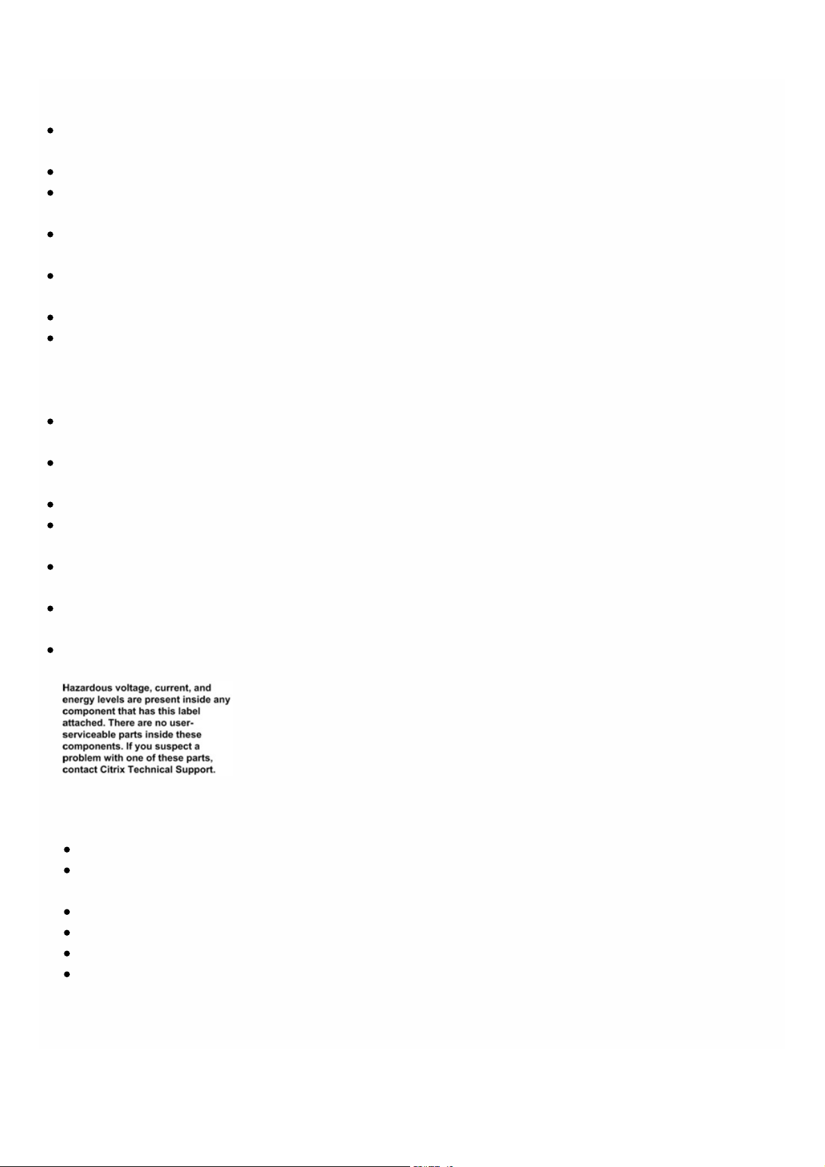
or repairing the appliance. When you touch both a live power source or wire and ground, any metal objects can heat up
rapidly and may cause burns, set clothing on fire, or fuse the metal object to an exposed terminal.
Use a regulating, uninterruptible power supply (UPS) to protect the appliance f rom power surges and voltage spikes, and
to keep the appliance operating in case of power failure.
Never stack t he appliance on top of any ot her server or elect ronic equipment.
All appliances are designed to be installed on power syst ems that use T N earthing. Do not install your device on a power
system that uses either TT or IT earthing.
Make sure that t he appliance has a direct physical connection to the earth during normal use. When installing or repairing
an appliance, always make sure that t he ground circuit is connected f irst and disconnected last.
Make sure that a fuse or circuit breaker no larger than 120 VAC, 15 A U.S. (240 VAC, 16 A international) is used on all
current-carrying conduct ors on the power system to which your appliances are connected.
Do not work alone when working with high voltage components.
Always disconnect the appliance f rom power before removing or installing any component. When disconnecting power,
first shut down the appliance, and then unplug the power cords of all the power supply units connect ed to the
appliance. As long as the power cord is plugged in, line voltages can be present in the power supply, even when the power
switch is OFF.
Do not use mat s designed to decrease stat ic electrical discharge as prot ection from electrical shock. Instead, use rubber
mat s that have been specifically designed as electrical insulators.
Make sure that t he power source can handle t he appliance's maximum power consumption rat ing with no danger of an
overload. Always unplug any appliance before performing repairs or upgrades.
Do not overload the wiring in your server cabinet or on your server room rack.
During thunderstorms, or anticipat ed thunderstorms, avoid performing any hardware repairs or upgrades until t he danger
of lightning has passed.
When you dispose of an old appliance or any components, follow any local and national laws on disposal of electronic
wast e.
To prevent possible explosions, replace expired batt eries with the same model or a manufacturer-recommended
substitute and follow the manufacturer’s instructions for battery replacement.
Never remove a power supply cover or any sealed part that has the following label:
Appliance Precautions
Det ermine the placement of each component in the rack before you inst all the rails.
Install the heaviest appliance first, at t he bot t om of the rack, and then work upward. Distribute the load on the rack
evenly. An unbalanced rack is hazardous.
Allow t he power supply units and hard drives t o cool bef ore touching them.
Install the equipment near an electrical outlet for easy access.
Mount equipment in a rack with suff icient airflow f or safe operation.
For a closed or multiple-unit rack assembly, the ambient operating temperat ure of t he rack environment might be
greater than the ambient t emperature of the room. Therefore, consider the lowest and highest operating
temperatures of t he equipment when making a decision about where to install the appliance in the rack.
© 1999-2017 Citrix Systems, Inc. All rights reserved. p.59https://docs.citrix.com
Page 57

Rack Precautions
Make sure that t he leveling jacks on the bottom of the rack are f ully extended to the f loor, with the full weight of
the rack resting on them.
For a single-rack installation, attach a stabilizer to the rack.
For a multiple-rack installation, couple (attach) the racks toget her.
Always make sure that t he rack is stable before ext ending a component f rom the rack.
Ext end only one component at a t ime. Extending two or more simultaneously might cause the rack to become
unstable.
The handles on the left and right of the front panel of t he appliance should be used only for ext ending the appliance
out of t he rack. Do not use t hese handles f or mounting the appliance on the rack. Use the rack-rail hardware,
described later, instead.
© 1999-2017 Citrix Systems, Inc. All rights reserved. p.60https://docs.citrix.com
Page 58

Installing the Hardware
Jan 31, 20 11
After you have determined that t he location where you will install your appliance meet s the environmental standards and
the server rack is in place according to the instructions, you are ready to install the hardware. Aft er you mount the
appliance, you are ready t o connect it to t he net work, to a power source, and to t he console terminal that you will use for
initial configuration. To complete the installation, you turn on the appliance. Be sure to observe the cautions and warnings
listed with the installation instructions.
Rack Mounting the Appliance
Most appliances can be installed in standard server racks that conform to EIA-310-D specification. The appliances ship with
a set of rails, which you must install bef ore you mount the appliance. T he only t ools that you need for installing an
appliance are a Phillips screwdriver and a flathead screwdriver.
Warning
If you are installing the appliance as the only unit in the rack, mount it at the bottom. If the rack contains other units, make sure that
the heaviest unit is at the bottom. If the rack has stabilizing devices available, install them before mounting the appliance.
Note
The SDX 8015/8400/8600 models have one rack unit. The other models have two rack units.
Each appliance ships with a mounting rail kit that contains two rail assemblies, one f or the left side and the other for the
right side of the appliance, and screws to at t ach the rails. An assembly consists of an inner rail and a rack rail. The supplied
rail kit is 28 inches long (38 inches extended). Contact your Citrix sales representative to order a 23-inch (33 inches
extended) rail kit.
Not e: The same rail kit is used for both square-hole and round-hole racks. See "Installing the Rail Assembly to the Rack" for
specific instructions for threaded, round-hole racks.
To mount the appliance, you must first install the rails and then install the appliance in the rack.
Perform the following tasks t o mount the appliance:
Remove the inner rails f rom the rail assembly.
Attach the inner rails to t he appliance.
Install the rack rails on the rack.
Install the appliance in the rack.
The appliance is shipped with rack-rail hardware. This hardware consists of t wo inner rails that you att ach to t he appliance,
one on each side, and a rack-rail assembly that you attach to the rack. The f ollowing figure illustrates the steps involved in
mounting the Citrix NetScaler SDX appliance t o a rack.
© 1999-2017 Citrix Systems, Inc. All rights reserved. p.61https://docs.citrix.com
Page 59

To remove the inner rails from the rail assembly
1. Place t he rail assembly on a flat surface.
2. Slide out the inner rail toward the f ront of the assembly.
3. Depress the latch until the inner rail comes all the way out of the rail assembly.
4. Repeat st eps 1 through 3 to remove the second inner rail.
To attach the inner rails to the appliance
1. Position the right inner rail behind the handle on the right side of the appliance.
2. Align the holes on the rail with the corresponding holes on t he side of t he appliance.
3. At t ach the rail to the appliance with the provided screws: 4 per side for a 1U appliance and 5 per side for a 2U appliance,
as shown in the following figure.
Figure 1. Attaching inner rails
4. Repeat st eps 1 through 3 to install the left inner rail on the other side of the appliance.
To install the rack rails on the rack
1. If you have a round-hole, threaded rack, skip to st ep 3.
2. Install square nut retainers into the f ront post and back post of the rack as shown in the following figures. Before
inserting a screw, be sure to align the square nut with the correct hole for your 1U or 2U appliance. The three holes are
not evenly spaced.
Figure 2. Installing Ret ainers into t he Front Rack Post s
Figure 3. Installing Ret ainers into t he Rear Rack Posts
© 1999-2017 Citrix Systems, Inc. All rights reserved. p.62https://docs.citrix.com
Page 60
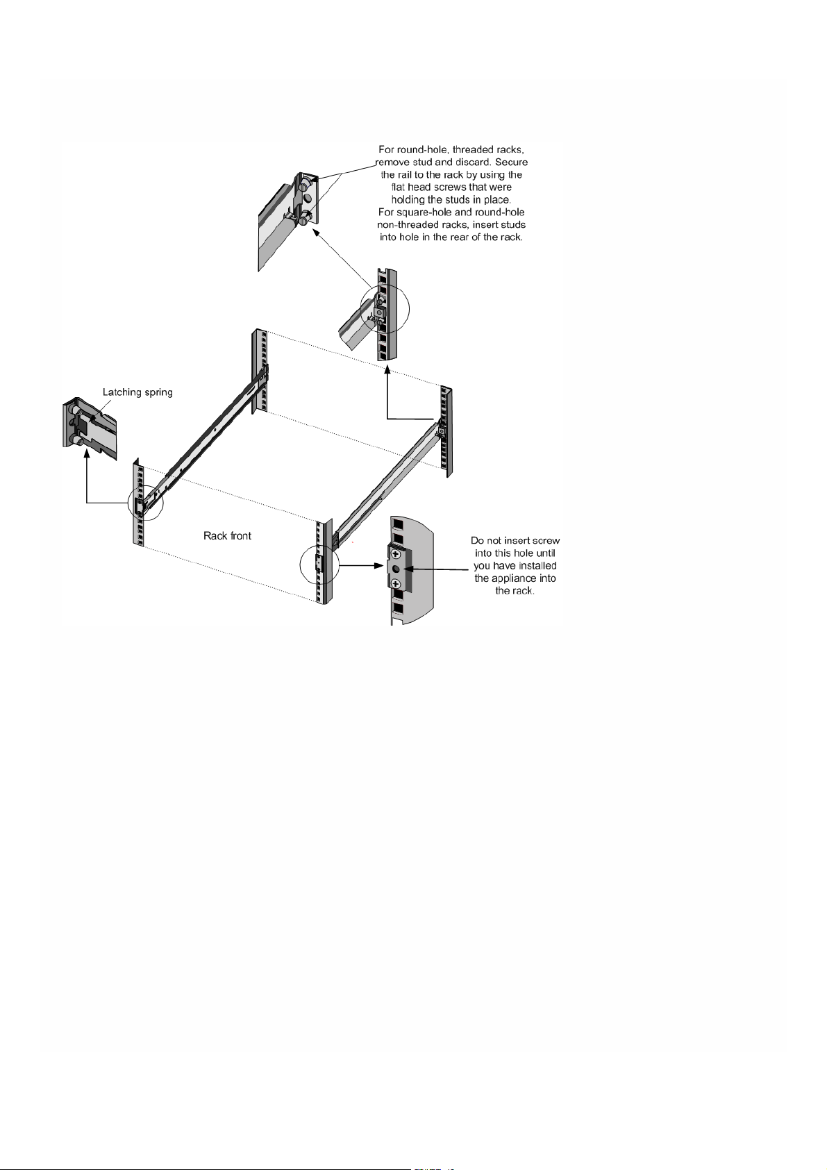
3. Install the adjustable rail assembly into the rack as shown in the following figures. Use a screw t o lock the rear rail flange
into t he rack. With the screw securing the rail in place, you can optionally remove t he latching spring.
Figure 4. Installing the Rail Assembly to t he Rack
To install the appliance in the rack
1. Align the inner rails, attached to the appliance, with the rack rails.
2. Slide the appliance into t he rack rails, keeping the pressure even on both sides.
3. Verify that the appliance is locked in place by pulling it all the way out f rom the rack.
Figure 5. Rack Mounting the Appliance
© 1999-2017 Citrix Systems, Inc. All rights reserved. p.63https://docs.citrix.com
Page 61
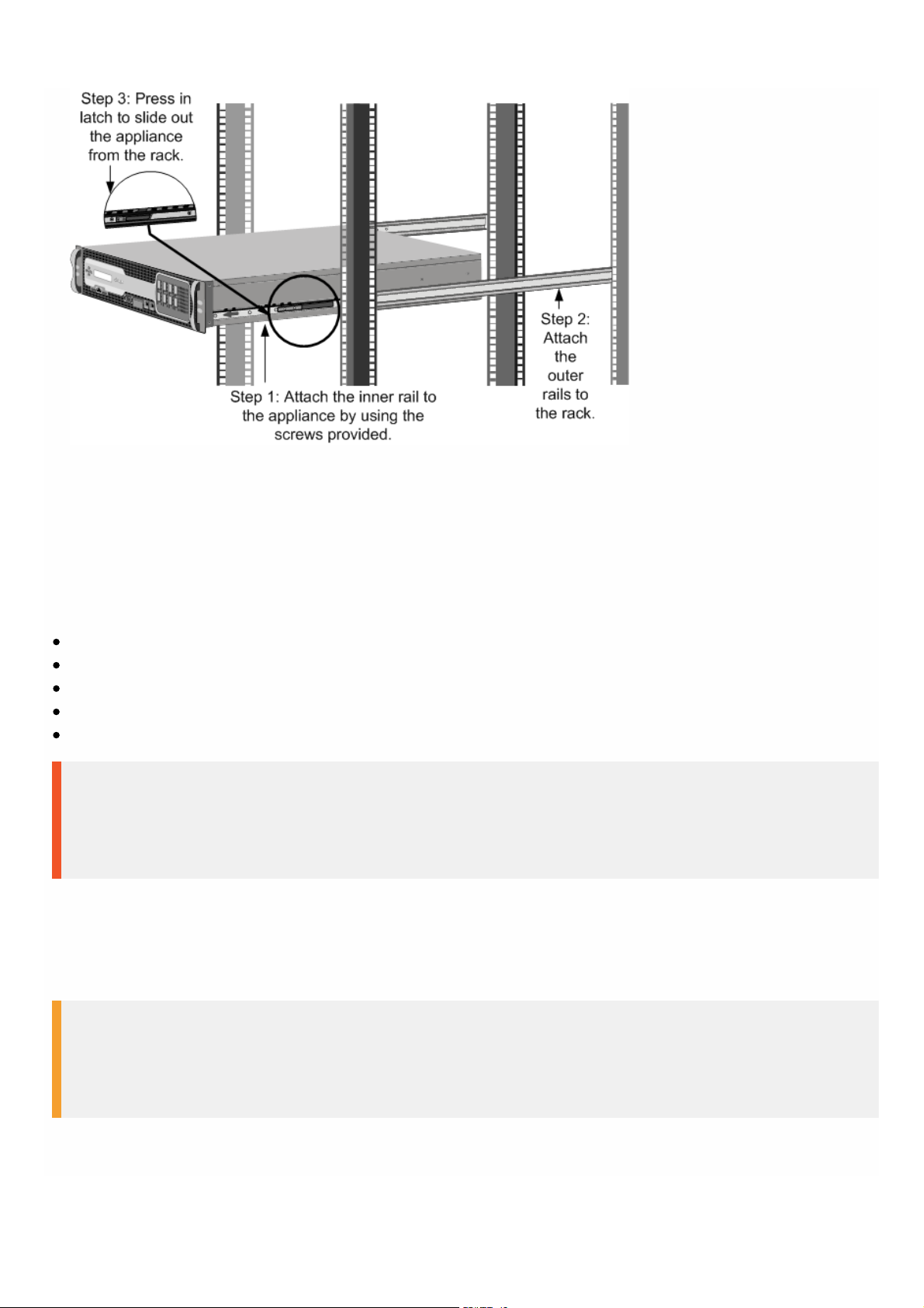
Installing and Removing 1G SFP Transceivers
A Small Form-Fact or Pluggable (SFP) is a compact transceiver that can operate at speeds of up to 1 gigabit per second and
is available in both copper and f iber types. Inserting a 1G SFP copper transceiver converts the 1G SFP port t o a 1000BASE-T
port. Inserting a 1G SFP f iber transceiver converts the 1G SFP port to a 1000BASE-X port. Auto-negotiation is enabled by
default on t he 1G SFP port into which you insert your 1G SFP t ransceiver. As soon as a link between the port and the
network is established, the speed and mode are matched on both ends of t he cable.
This section applies to the f ollowing SDX models:
SDX 8015/8400/8600
SDX 11500/13500/14500/16500/18500/20500
SDX 11515/11520/11530/11540/11542
SDX 22040/22060/22080/22100/22120
SDX 24100/24150
Important
NetScaler appliances do not support 1G SFP transceivers from vendors other than Citrix Systems. Attempting to install third-party 1G
SFP trans ceivers on your NetScaler appliance voids the warranty.
Insert 1G SFP transceivers into t he 1G SFP ports on the f ront panel of the appliance. Frequent installation and removal of
transceivers shortens their life span. Follow the removal procedure carefully to avoid damaging the 1G SFP transceiver or
the appliance.
Warning
Do not install the transceivers with the cables attached. Doing so can damage the cable, the connector, or the optical interface of the
transceiver.
© 1999-2017 Citrix Systems, Inc. All rights reserved. p.64https://docs.citrix.com
Page 62

To install a 1G SFP transceiver
1. Remove the 1G SFP t ransceiver carefully from its box.
Danger: Do not look direct ly into f iber optic transceivers or cables. T hey emit laser beams that can damage your eyes.
2. Align the 1G SFP transceiver to the front of the 1G SFP transceiver port on the f ront panel of the appliance, as shown in
the following figure.
Not e: The illust ration in the f ollowing figures might not represent your actual appliance.
Figure 6. Installing a 1G SFP transceiver
3. Hold the 1G SFP transceiver bet ween your thumb and index finger and insert it into the 1G SFP transceiver port, pressing
it in until you hear the t ransceiver snap into place.
4. Lock the transceiver.
5. Verify that the LED is green and blinks twice, which indicates that t he t ransceiver is functioning correctly.
6. If you are using a f iber 1G SFP transceiver, do not remove t he dust caps attached to the transceiver and the cable until
you are ready t o insert t he cable.
To remove a 1G SFP transceiver
1. Disconnect the cable f rom the 1G SFP transceiver. If you are using a f iber optic cable, replace the dust cap on the cable
before putt ing it away.
2. Unlock the 1G SFP t ransceiver.
3. Hold the 1G SFP transceiver bet ween your thumb and index finger and slowly pull it out of t he port.
4. If you are removing a f iber 1G SFP t ransceiver, replace t he dust cap before putt ing it away.
5. Put the 1G SFP transceiver into its original box or another appropriat e container.
Warning
Do not look directly into fiber optic transceivers or cables. T hey emit laser beams that can damage your eyes .
Installing and Removing 40G QSFP+ Ports and 10G SFP+ Transceivers
A 10-Gigabit SFP+ is a compact optical transceiver that can operate at speeds of up to 10 gigabits per second.
© 1999-2017 Citrix Systems, Inc. All rights reserved. p.65https://docs.citrix.com
Page 63

Autonegotiation is enabled by default on the 10G SFP+ ports into which you insert your 10G SFP+ t ransceiver. As soon as a
link between the port and the network is established, the mode is matched on both ends of t he cable and for 10G SFP+
transceivers, the speed is also autonegotiated.
This section applies to the f ollowing SDX models:
SDX 8015/8400/8600
SDX 11500/13500/14500/16500/18500/20500
SDX 11515/11520/11530/11540/11542
SDX 14020/14030/1404 0/14060/14080/14100
SDX 14020-40G/14040-40G/14060-40G/14080-40G/14100-40G
SDX 14040-40S/14060-40S/14080-40S/14100-40S
SDX 14030 FIPS/14060 FIPS/ 14080 FIPS
SDX 17500/19500/21500
SDX 17550/19550/20550/21550
SDX 22040/22060/22080/22100/22120
SDX 24100/24150
SDX 25160A/25100A
SDX 25160A-40G/25100A-40G
Important
NetScaler appliances do not support support 4 0G QSFP+/10G SFP+ transceivers provided by vendors other than Citrix Sys tems.
Attempting to install third-party support 40G QSFP+/10G SFP+ transceivers on your NetScaler appliance voids the warranty.
Insert the support 40G QSFP+/10G SFP+ transceivers into t he support 40G QSFP+/10G SFP+ ports on the front panel of
the appliance. Frequent installation and removal of transceivers shortens their lif e span. Follow the removal procedure
carefully t o avoid damaging the transceiver or the appliance.
Warning
Do not install the transceivers with the cables attached. Doing so can damage the cable, the connector, or the optical interface of the
transceiver.
To install a support 40G QSFP+/10G SFP+ transceiver
1. Remove the support 40G QSFP+/10G SFP+ transceiver carefully f rom its box.
2. Align the support 40G QSFP+/10G SFP+ transceiver to the front of t he support 40G QSFP+/10G SFP+ transceiver port
on the front panel of t he appliance.
3. Hold the support 40G QSFP+/10G SFP+ t ransceiver between your thumb and index f inger and insert it into the support
40G QSFP+/10G SFP+ transceiver port, pressing it in until you hear the t ransceiver snap into place.
4. Move the locking hinge to t he DOWN position.
5. Verify that the LED is green and blinks twice, which indicates that t he t ransceiver is functioning correctly.
6. Do not remove the dust caps attached to the transceiver and cable until you are ready to insert t he cable.
To remove a support 40G QSFP+/10G SFP+ transceiver
© 1999-2017 Citrix Systems, Inc. All rights reserved. p.66https://docs.citrix.com
Page 64

1. Disconnect the cable f rom the support 40G QSFP+/10G SFP+ transceiver. Replace t he dust cap on the cable before
putting it away.
2. Unlock the support 40G QSFP+/10G SFP+ transceiver by moving the locking hinge to t he UP position.
3. Hold the support 40G QSFP+/10G SFP+ t ransceiver between your thumb and index f inger and slowly pull it out of the
port.
4. Replace the dust cap on the transceiver bef ore putting it away.
5. Put the support 40G QSFP+/10G SFP+ into its original box or another appropriat e container.
Warning
Do not look directly into fiber optic transceivers or cables. T hey emit laser beams that can damage your eyes .
Connecting the Cables
When the appliance is securely mounted on the rack, you are ready t o connect the cables. Ethernet cables and the optional
console cable are connected first. Connect the power cable last.
Warning
Before installing or repairing the appliance, remove all jewelry and other metal objects that might come in contact with power
sources or wires. When you touch both a live power source or wire and ground, any metal objects can heat up rapidly and cause
burns, set clothing on fire, or fuse the metal object to an exposed terminal.
Connecting the Ethernet Cables
Ethernet cables connect your appliance to the network. T he type of cable you need depends on the type of port used to
connect t o the network. Use a category 5e or category 6 Ethernet cable with a st andard RJ-45 connector on a
10/100/1000BASE-T port or 1G SFP copper transceiver. Use a fiber optic cable with an LC duplex connector with a 1G SFP
fiber transceiver, 10G SFP+, or 40G QSFP+ transceiver. The type of connector at t he other end of the fiber optic cable
depends on the port of the device that you are connecting to.
To connect an Ethernet cable to a 10/100/1000BASE-T port or 1G SFP copper transceiver
1. Insert the RJ-45 connector on one end of your Ethernet cable into an appropriate port on the front panel of t he
appliance, as shown in the f ollowing figure.
Figure 7. Inserting an Ethernet cable
2. Insert the RJ-45 connector on the ot her end into t he t arget device, such as a router or switch
3. Verify that the LED glows amber when the connection is est ablished.
© 1999-2017 Citrix Systems, Inc. All rights reserved. p.67https://docs.citrix.com
Page 65

To connect t he Ethernet cable to a 1G SFP fiber, 10G SFP+, or 40G QSFP+ transceiver
1. Remove the dust caps from the transceiver and cable.
2. Insert t he LC connector on one end of the fiber optic cable into t he appropriat e port on t he f ront panel of the
appliance.
3. Insert t he connector on the ot her end into t he t arget device, such as a router or switch.
4. Verify t hat the LED glows amber when the connection is est ablished.
Connecting the Console Cable
You can use the console cable to connect your appliance to a computer or terminal, from which you can configure the
appliance. Alternatively, you can use a computer connected to t he net work. Before connecting the console cable,
configure the computer or terminal to support VT100 terminal emulation, 9600 baud, 8 dat a bits, 1 stop bit, parity, and flow
control set t o NONE. T hen connect one end of t he console cable to the RS232 serial port on the appliance and the other
end to the computer or terminal.
To connect t he console cable to a computer or terminal
1. Insert the DB-9 connector at t he end of the cable into the console port t hat is located on the f ront panel of the
appliance, as shown in the f ollowing figure.
Figure 8. Inserting a console cable
Not e: To use a cable with an RJ-45 converter, insert the optional converter provided into t he console port and at t ach
the cable to it.
2. Insert t he RJ-45 connector at t he other end of t he cable into the serial port of the computer or terminal.
Connecting the Power Cable
An SDX 8015/8400/8600 appliance has one power cable. All the ot her appliances come with two power cables, but they
can also operate if only one power cable is connected. A separate ground cable is not required, because the three-prong
plug provides grounding.
To connect t he appliance to the power source
1. Connect one end of the power cable t o the power outlet on the back panel of the appliance, next t o the power supply,
as shown in the following figure.
Figure 9. Inserting a power cable
© 1999-2017 Citrix Systems, Inc. All rights reserved. p.68https://docs.citrix.com
Page 66

2. Connect the ot her end of the power cable to a standard 110V/220V power outlet.
3. If a second power supply is provided, repeat steps 1 and 2 to connect the second power supply.
Note
The following SDX appliances emit a high-pitched alert if one power supply fails, or if you connect only one power cable to the
appliance. To silence the alarm, you can press the small red button located on the back panel of the appliance.
SDX 11500/13500/14 500/16500/18500/20500
SDX 11515/11520/11530/11540/11542
SDX 17 500/19500/21500
SDX 17 550/19550/20550/21550
Switching on the Appliance
After you have installed the appliance in a rack and connected the cables, verify t hat the power cable is properly
connected. If you have installed a second power supply, make sure the second cable is connected to an outlet f or a
diff erent circuit than the first. After verifying the connect ions, you are ready t o switch on the appliance.
To switch on the appliance
1. Verify that the appliance is connect ed through a console or Ethernet port. This will ensure that you can configure the
appliance af ter it is switched on.
2. Press the ON/OFF toggle power switch on t he back panel of t he appliance.
Warning
Be aware of the location of the emergency power off (EPO) switch, so that if an electrical accident occurs you can quickly remove
power from the appliance.
© 1999-2017 Citrix Systems, Inc. All rights reserved. p.69https://docs.citrix.com
Page 67

Initial Configuration
May 11, 20 17
After you have installed your appliance in a rack, you are ready t o perform the initial configuration. To perform the initial
configuration, you can use the Management Service user interface or the serial console. You can access the Management
Service user interface from any computer that is on the same network as the new SDX appliance. If you do not have a
computer on the same network, use the serial console to perform the initial configuration of the SDX appliance. Citrix
recommends that, as soon as you complete t he initial configuration, you change the root -user password. For information
about changing the root-user password, click here.
Det ermine the f ollowing information for performing the initial configuration.
NetScaler SDX IP address and subnet mask: The management IP address and the mask used to define the subnet in
which the SDX appliance is located. This IP address is used to access the NetScaler SDX Management Service user
interface.
XenServer IP address: T he IP address of the XenServer hypervisor.
Def ault gat eway: The IP address of t he router that forwards traff ic out of the appliance’s subnet. T he def ault gateway
should be in the same subnet as the NSIP address.
Root password: T he root user (nsroot) has full administrative privileges on the appliance. The root password is used to
authenticat e the root user. The default root password is nsroot . You can change this password during initial
configuration of the appliance.
Initial Configuration through the Management Service User Interface
To set up the appliance by using the Management Service user interface, connect a workstation or laptop to the same
network as the appliance.
To configure the NetScaler SDX appliance by using the Management Service user
interface
1. Connect the NetScaler SDX appliance t o a management workstat ion or network by using interface 0/1.
2. Open a browser and type: http://192.168.100.1
Not e: The Net Scaler SDX Management Service is preconfigured with the IP address 192.168.100.1 and the XenServer
hypervisor is preconfigured with the IP address 192.168.100.2.
3. In the User Name box, type nsroot.
4. In the Password box, type nsroot.
5. In the navigation pane, click System.
6. In the details pane, under Setup Appliance, click Network Configuration and enter values for the f ollowing parameters:
Interface*— The management interface that connects the appliance t o a management workstat ion or network.
Possible values: 0/1, 0/2. Default: 0/1.
XenServer IP Address*— The IP address of t he XenServer.
Management Service IP Address*— The IP address that is used to access the Management Service by using a Web
browser.
Not e: The XenServer IP address and Management Service IP address should be in the same subnet .
Netmask*— The mask used to def ine the subnet in which the SDX appliance is located.
Gateway*— The IP address of the router that forwards traff ic out of the appliance's subnet.
DNS Server— The IP address of t he DNS server.
© 1999-2017 Citrix Systems, Inc. All rights reserved. p.70https://docs.citrix.com
Page 68

*A required parameter
7. Click OK, and then click Close.
8. T o confirm t hat t he NetScaler SDX appliance is configured correctly, you can either ping the new Management Service
IP address or use the new IP address to open the user interface in a browser.
Not e: After changing the net work configuration, close all browser inst ances and open a new browser instance to access
the appliance.
Initial Configuration through the Serial Console
To perform initial configuration of the SDX appliance f rom outside the L2 domain, connect to the console port of the
appliance and follow the instructions carefully.
Not e: networkconfig utility is available from build 72.5 and lat er.
To configure the NetScaler SDX appliance by using the serial console
1. Connect the console cable into your appliance.
2. Connect the ot her end of the cable to your computer and run the vt100 terminal emulat ion program of your choice.
For Microsof t Windows, you can use HyperTerminal.
For Apple Macintosh OSX, you can use the GUI-based Terminal program or the shell-based telnet client.
Not e: OSX is based on the FreeBSD UNIX platform. Most standard UNIX shell programs are available from the OSX
command line.
For UNIX-based workstat ions, you can use the shell-based telnet client or any supported terminal emulat ion program.
3. Press ENTER. The terminal screen displays the Logon prompt.
Not e: You might have to press ENTER two or three times, depending on which terminal program you are using.
4. Log on t o the appliance with the administrator credentials. The def ault credentials for username and password are root
and nsroot respectively.
5. At the prompt, type: ssh nsroot@169.254.0.10 When prompted f or the password, type nsroot.
6. At the shell prompt, type: networkconfig
You can now use the new IP address to log on to the Management Service user interface.
Changing the Password of the Default User Account
The default user account provides complete access t o all features of the Citrix NetScaler SDX appliance. Therefore, to
preserve security, the nsroot account should be used only when necessary, and only individuals whose duties require full
access should know the password for the nsroot account. Citrix recommends changing the nsroot password frequently. If
you lose the password, you can reset the password to t he def ault by reverting the appliance settings t o factory defaults ,
and you can then change the password.
You can change the password of the default user account in t he Users pane. In the Users pane, you can view the following
details:
Name
Lists the user accounts configured on the SDX appliance.
Permission
Displays the permission level assigned to t he user account.
To change the password of the default user account
1. On the Configuration tab, in the navigation pane, expand System, and then click Users.
© 1999-2017 Citrix Systems, Inc. All rights reserved. p.71https://docs.citrix.com
Page 69

2. In the Users pane, click the def ault user account, and then click Modify.
3. In the Modify System User dialog box, in Password and Confirm Password, enter the password of your choice.
4. Click OK.
© 1999-2017 Citrix Systems, Inc. All rights reserved. p.72https://docs.citrix.com
Page 70

Getting Started with the Management Service User
Interface
Jan 31, 20 11
To begin configuring, managing, and monitoring the appliance, the Management Service, and the virtual instances, you need
to connect to t he Management Service user interface by using a browser, and then provision the virtual instances on the
appliance.
Logging on to the Management Service User Interface
You can connect to t he Management Service user interface by using one of the f ollowing supported browsers:
Internet Explorer
Google Chrome
Apple Safari
Mozilla Firefox
To log on to the Management Service user interface
1. In your Web browser address field, type one of the following:
htt p://Management Service IP Address
or
htt ps://Management Service IP Address
2. On the Login page, in User Name and Password, type t he user name and password of the Management Service. The
default user name and password are nsroot and nsroot. However, Citrix recommends that you change the password
aft er initial configuration. For inf ormation about changing the nsroot password, see Changing the Password of the
Def ault User Account .
3. Click Show Options, and then do the following:
1. In the St art in list, select the page that must be displayed immediately af t er you log on to t he user interface. The
available options are Home, Monitoring, Configuration, Documentat ion, and Downloads. For example, if you want the
Management Service to display the Configuration page when you log on, select Configuration in the St art in list.
2. In Timeout, type the length of t ime (in minutes, hours, or days) after which you want the session to expire. The
minimum timeout value is 15 minutes.
The St art in and Timeout settings persist across sessions. Their default values are restored only after you clear the
cache.
4. Click Login to log on to the Management Service user interface.
Initial Setup Wizard
You can use the Setup Wizard to complete all the first t ime configurations in a single flow.
You can use the wizard to configure network configuration det ails and syst em set tings, change t he def ault administrative
password, and manage and updat e licenses.
You can also use this wizard to modify the network configuration det ails that you specified for the NetScaler SDX
© 1999-2017 Citrix Systems, Inc. All rights reserved. p.73https://docs.citrix.com
Page 71

appliance during initial configuration.
To access the wizard, navigat e to Configuration > System and, under Set Up Appliance, click Setup Wizard.
On the Platform Configuration page, you can configure net work configuration details, system settings, and change the
default administrative password.
Interface*— The interface through which clients connect to the Management Service. Possible values: 0/1, 0/2. Def ault:
0/1.
XenServer IP Address*— IP address of t he XenServer server.
Management Service IP Address*— IP address of t he Management Service.
Netmask*— Mask for the subnet in which the SDX appliance is located.
Gateway*— Def ault gateway f or the net work.
DNS Server— IP address of the DNS server.
Under Syst em Settings, you can specify that t he Management Service and a Net Scaler instance should communicate with
each other only over a secure channel. You can also restrict access to t he Management Service user interface. Clients can
log on the Management Service user interface only by using htt ps.
You can modify t he time zone of the Management Service and the XenServer server. The def ault time zone is UTC. You can
change the Administrat ive password by selecting the Change Password check box and typing the new password.
Under Manage Licenses you can manage and allocat e licenses. You can use your hardware serial number (HSN) or your
license activation code (LAC) to allocate your licenses. Alternatively, if a license is already present on your local computer,
you can upload it t o the appliance.
Select t he licenses on the appliance and click Done to complete the initial configuration.
Provisioning Instances on an SDX Appliance
You can provision one or more NetScaler or third-party instances on the SDX appliance by using the Management Service.
The number of instances that you can install depends on the license you have purchased. If the number of instances added
is equal to the number specified in the license, the Management Service does not allow provisioning more instances.
For information about provisioning NetScaler instances, see NetScaler VPX Virtual Machines .
For information about provisioning third-party instances, see T hird-Party Virtual Machines.
Console Access
You can access the console of NetScaler instances, the Management Service, XenServer, and third party VMs from the
Management Service interface. This is particularly helpful in debugging and troubleshoot ing the instances host ed on the
NetScaler SDX appliance.
To access the console of VMs, navigat e to the instance listing, select t he VM f rom the list, and under Action drop down
menu, click Console Access.
To access the console of Management Service or XenServer, navigate to Configuration > Syst em, and under Console
Access, click Management Service or XenServer link.
Not e: Console access is not supported by the Internet Explorer browser. Citrix recommends using the console access
feature through Management Service HT TPS sessions only.
© 1999-2017 Citrix Systems, Inc. All rights reserved. p.74https://docs.citrix.com
Page 72

Management Service Statistics
The dashboard now includes Management Service Statistics for monitoring use of memory, CPU, and disk resources by t he
Management Service on Net Scaler SDX appliance.
Single Sign-On to the Management Service and the Net Scaler Instances
Logging on to the Management Service gives you direct access to the NetScaler instances t hat are provisioned on the
appliance, if the instances are running release 10 build 53 and later. If you log on to t he Management Service by using your
user credentials, you do not have to provide the user credentials again for logging on to an instance. By def ault, the
Timeout value is set t o 30 minutes and the configuration tab is opened in a new browser window.
Managing the Home Page
The Management Service Home page provides you with a high-level view of t he performance of the SDX appliance and the
instances provisioned on your appliance. SDX appliance and instance informat ion is displayed in gadgets that you can add
and remove depending on your requirement.
The following gadgets are available on the Home page by default.
System Resources
Displays the total number of CPU cores, total number of SSL chips, number of f ree SSL chips, total memory, and free
memory on the appliance.
System CPU | Memory Usage (%)
Displays the percentage of CPU and memory utilization of the appliance in graphical format.
System WAN/LAN Throughput (Mbps)
Displays the total throughput of the SDX appliance for incoming and outgoing traff ic in a graph that is plotted in real time
and updated at regular intervals.
Net Scaler Instances
Displays the properties of t he NetScaler instances. The properties displayed are Name, VM State, Instance State, IP
Address, Rx (Mbps), Tx (Mbps), HTTP Req/s, and CPU Usage (%) and Memory Usage (%).
Not e: On first log on, the Home page does not display any dat a related to the Net Scaler instances because you have not
provisioned any instances on your appliance.
Health Monitoring Events
Displays the last 25 events, with their severity, message, and the date and time t hat the event occurred.
You can do the f ollowing on the Home page:
View and hide NetScaler instance det ails
You can view and hide the details of a particular Net Scaler instance by clicking the name of the instance in the Name
column. You can also click Expand All to expand all the instance nodes and Collapse All to collapse all the instance nodes.
Add and remove gadgets
© 1999-2017 Citrix Systems, Inc. All rights reserved. p.75https://docs.citrix.com
Page 73

You can also add gadgets to view additional system information.
To add these gadgets, click the arrow (<<) button at the t op right corner of the Home page, enter keywords in the search
box, and then click Go. The allowed characters are: a-z, A-Z, 0-9, ^, $, *, and _. Click Go without typing any characters in the
search box to display all the gadgets that are available. Aft er the gadget is displayed, click Add to dashboard.
Currently, you can add the following gadgets t o the Home page:
Hypervisor Det ails
The Hypervisor Details gadget displays details about XenServer uptime, edition, version, iSCSI Qualified Name (IQN), product
code, serial number, build date, and build number.
Licenses
The Licenses gadget displays details about t he SDX hardware platf orm, the maximum number of instances supported on
the plat f orm, the maximum supported throughput in Mbps, and the available throughput in Mbps.
If you remove a gadget t hat is available on the Home page by default, you can add them back to the Home page by
performing a search for the gadget, as described earlier.
© 1999-2017 Citrix Systems, Inc. All rights reserved. p.76https://docs.citrix.com
Page 74

Upgrading the Components of a NetScaler SDX
Appliance
Dec 11, 20 17
Upgrading a NetScaler SDX appliance involves upgrading one or more of the SDX components - the Management Service,
the XenServer hypervisor, and the NetScaler instances. Based on your requirements, you can choose the component of the
NetScaler SDX appliance you want to upgrade. It is generally recommended to upgrade the Management Service first, then
the XenServer, then the NetScaler instances (if necessary).
Citrix recommends using t he latest version of XenServer supported on the corresponding version of the Management
Service. Also, make sure you apply the latest versions of the Supplemental Packs and Hotfixes. See the Supported Versions
table for the recommended Management Service, XenServer, and NetScaler software versions on the NetScaler SDX
appliance.
Upgrade Scenarios and Steps
The following table summarizes scenarios and the upgrade st eps you must f ollow t o upgrade your NetScaler SDX appliance
under each scenario.
Upgrade
Type
User Scenarios Upgrade St eps Tips
Management
Service
Upgrading to a later
version to enable
new NetScaler SDX
features.
Downgrading to a
previous version
because of issues
with the current
version.
Upgrading the
management service
before upgrading
the XenServer
version.
1. Check the existing versions
running on Management Service
and Xenserver.
2. See t he See t he Supported
Versions table.
3. Upgrade the Management
Service.
You can upgrade t he
Management Service without
shutting down t he NetScaler
instances.
XenServer Upgrading to a later
version of XenServer to
enable new NetScaler
SDX feat ures t hat are
supported on a specific
version of XenServer.
For example:
Provisioning third Party
VMs or enabling LACP
1. Check the existing versions
running on Management Service
and XenServer.
2. See t he See t he Supported
Versions table t o see if the
current Management Service
version supports t he XenServer
upgrade. If not , upgrade t he
Management Service to the
Citrix recommends that you back
up the appliance's configuration
before upgrading the XenServer.
During the upgrade process the
NetScaler SDX appliance reboots
multiple times, so, you might want
to secure a serial console access
to the NetScaler SDX appliance.
During the upgrade, all the VMs
© 1999-2017 Citrix Systems, Inc. All rights reserved. p.77https://docs.citrix.com
Page 75

is possible only if with
XenServer is running
version 6.1.0.
appropriate version.
3. Upgrade the XenServer
hypervisor.
hosted on the appliance are
rebooted.
After you upgrade, check the
supplemental pack version on t he
Management Service and be sure
to install all the required Xenserver
hotfixes and supplemental packs if
required.
Do not upgrade XenServer using
the command line interface.
XenServer
Hot Fix
Applying a hot fix when
a specific bug is
resolved on the
XenServer.
1. Check the existing versions
running on Management Service
and Xenserver.
2. Check the See the Supported
Versions table.
3. Check the Net Scaler download
page for XenServer Hot Fixes
and apply any that are available.
Citrix recommends that you
backup the appliance's
configuration before applying a
XenServer hotf ix.
You need not upgrade the
XenServer version when you apply
a hotf ix.
When applying hot f ixes on the
NetScaler download page, apply
them in them in the chronological
order.
XenServer
Supplemental
Pack
Installing a XenServer
Supplemental Pack
that has a specific
NetScaler SDX
enhancements.
For example, the
NetScaler SDX health
monitoring feature is
supported on
XenServer 6.0 with SP
100003 or later.
1. Check the existing versions
running on Management Service
and XenServer.
2. Check the See the Supported
Versions
table.
3. Check the Net Scaler download
page for XenServer
Supplemental Pack and install
any that are available.
Supplemental Packs are version
specific. Be sure to apply the
correct version f or your XenServer
version.
NetScaler
Instance
Upgrading to a later
NetScaler version.
1. Check the existing versions
running on Management Service,
Xenserver, and Net Scaler
instance.
2. Check the See the Supported
Versions
table.
3. Upgrade the NetScaler instance.
If you are looking for a particular
enhancement, make sure t hat you
are running the latest NetScaler
version and check the XenServer
and Management Service version
requirements for that
enhancement.
Upgrade
Type
User Scenarios Upgrade St eps Tips
© 1999-2017 Citrix Systems, Inc. All rights reserved. p.78https://docs.citrix.com
Page 76

Upgrading the Management Service
Apr 18 , 2015
The process of upgrading the Management Service involves uploading the build file of the target build and the
documentat ion file t o the SDX appliance, and then upgrading the Management Service.
You can upload the Management Service build and documentation files f rom a client computer to the SDX appliance. You
can also download build and documentation files to a local computer as a backup.
To upload the Management Service build file
1. In the navigat ion pane, expand Management Service, and then click Software Images.
2. In the Sof tware Images pane, click Upload.
3. In the Upload Management Service Sof t ware Image dialog box, click Browse, navigate t o the folder that contains the
build f ile, and then double-click the build file.
4. Click Upload.
To create a backup by downloading a Management Service build file
1. In the Software Images pane, select t he f ile you want to download, and then click Download.
2. In the message box, from the Save list, select Save as.
3. In the Save As message box, browse to the location where you want t o save t he f ile, and then click Save.
To upload the Management Service documentation file
1. In the navigat ion pane, expand Management Service, and then click Software Images.
2. In the Sof tware Images pane, on the Documentat ion Files tab, click Upload.
3. In the Upload Management Service Documentation File dialog box, click Browse, navigate to the f older that contains
the documentat ion file, and then double-click the f ile.
4. Click Upload.
To create a backup by downloading a Management Service documentation file
1. In the Software Images pane, select t he f ile you want to download, and then click Download.
2. In the message box, from the Save list, select Save as.
3. In the Save As message box, browse to the location where you want t o save t he f ile, and then click Save.
Upgrading the Management Service to a Later Version
After you have uploaded the Management Service image to t he SDX appliance, use this image to upgrade the version of
the Management Service. T he Management Service will rest art after the upgrade. Restarting the Management Service
does not af fect your NetScaler VPX instances and the appliance.
To upgrade the Management Service
1. In the navigat ion pane, click System.
2. In the System pane, under System Administration, click Upgrade Management Service.
3. In the Upgrade Management Service dialog box, in Software Image, select the sof tware image file to which you want to
upgrade the Management Service.
4. In Documentat ion File, select the documentat ion f ile you want t o use during upgrade.
© 1999-2017 Citrix Systems, Inc. All rights reserved. p.79https://docs.citrix.com
Page 77

5. Click OK.
© 1999-2017 Citrix Systems, Inc. All rights reserved. p.80https://docs.citrix.com
Page 78

Upgrading the XenServer Software
Apr 18 , 2015
You need to upgrade to XenServer version 6.1.0 to enable LACP and provisioning of third-party virtual machines (instances).
The process of upgrading the XenServer software involves uploading the build file of the t arget build to the Management
Service, and then upgrading the XenServer software.
You can upload the XenServer build files from a client computer to the SDX appliance. You can also download the build files
to a local computer as a backup.
To upload the XenServer build file
1. In the navigat ion pane, expand Management Service, and then click XenServer Files.
2. In the details pane, click t he ISO Images tab, and then click Upload.
3. In the Upload XenServer ISO Image File dialog box, click Browse, navigate t o the folder that contains t he build file, and
then double-click the build file.
4. Click Upload.
To create a backup by downloading a XenServer build file
1. In the details pane, click the ISO Images tab, select t he f ile you want to download, and then click Download.
2. In the message box, from the Save list, select Save as.
3. In the Save As message box, browse to the location where you want t o save t he f ile, and then click Save.
Upgrading the Software
You can upgrade to the latest version of the XenServer software. The upgrade process may take up to 20 minutes. Before
upgrading the sof t ware, upload the ISO image file to the appliance. The current version of t he software is displayed in the
Upgrade XenServer dialog box.
To upgrade the XenServer software
1. In the navigat ion pane, click System.
2. In the details pane, click Upgrade XenServer.
3. In the Upgrade XenServer dialog box, select the Image file f rom the list.
4. Click OK, and then click Close.
© 1999-2017 Citrix Systems, Inc. All rights reserved. p.81https://docs.citrix.com
Page 79

Uploading and Applying a XenServer Hotfix
Mar 21, 20 12
You can upload the XenServer hotfix files from a client computer to the SDX appliance. You can also download the hotfix
files t o a local computer as a backup.
Important: Citrix recommends that you make a backup bef ore applying a XenServer hotf ix. Apply only the hotfix that is
available in the NetScaler download page.
XenServer 6.0 should be installed on your SDX appliance. To upgrade to XenServer 6.0, see Upgrading the XenServer
Sof tware to a Lat er Version .
To upload and apply a XenServer hotfix
1. In the navigat ion pane, expand Management Service, and then click XenServer Files.
2. In the Hot f ixes pane, click Upload.
3. In the Upload XenServer Hotf ix dialog box, click Browse, navigat e to the f older that contains the build file, and then
double-click t he build file.
4. Click Upload. The hotfix appears in the details pane.
5. Click Apply. In the Confirm dialog box, click Yes.
Not e: In the details pane, if t he Af ter Apply Guidance column contains "rest arthost ", then restart the appliance.
Important: If the appliance does not restart correctly, perform a factory reset , and then restore the conf iguration from
the backup that was t aken before applying the hot f ix. For informat ion about performing a f actory reset , see Performing
a Fact ory Reset. For information about restoring the conf igurat ion, see Backing Up and Restoring the Configuration
Dat a of the SDX Appliance.
To create a backup by downloading a XenServer hot fix file
1. In the Hotfixes pane, select the f ile you want to download, and then click Download.
2. In the message box, from the Save list, select Save as.
3. In the Save As message box, browse to the location where you want t o save t he f ile, and then click Save.
© 1999-2017 Citrix Systems, Inc. All rights reserved. p.82https://docs.citrix.com
Page 80

Installing the XenServer Supplemental Pack
Aug 26, 20 16
The XenServer supplemental pack for NetScaler SDX contains updated igb-modules, ixgbe-modules, and iovirt plugins. It
provides support for the f ollowing features:
Layer 2 networking
Virtual MAC
System health monitoring support
Creating a clust er of Net Scaler instances
MAC-address assignment by t he system administrator
Rest ricting a VLAN to a specific virtual interface
Link aggregation control protocol (LACP)
The following table lists the supplemental pack version required for specific XenServer and Management Service versions.
Table 1. Supplemental Pack Version Supported on t he NetScaler SDX Appliance
XenServer Version Supplemental Pack Version Management Service Version
XenServer 6.0 Build 100003 Release 10.0, Build 69.4 or later
XenServer 6.0 Build 100006 Release 10.1, Build 112.13 or lat er
The appliance and all the instances restart after you install the supplemental pack.
To upload the supplemental pack
1. In the navigat ion pane, expand Management Service, and then click XenServer Files.
2. In the Supplemental Packs pane, click Upload.
3. In the Upload XenServer Supplemental Pack dialog box, click Browse, navigat e to the f older that contains the .iso file,
and then double-click the f ile.
4. Click Upload. The supplemental pack appears in the details pane.
To install the supplemental pack
XenServer 6.0 should be installed on your SDX appliance. To upgrade to XenServer 6.0, see Upgrading the XenServer
Sof tware to a Lat er Version.
1. In the Supplemental Packs pane, click Install.
2. In the Confirm dialog box, click Yes.
To create a backup by downloading the supplemental pack
1. In the Supplemental Packs pane, select the f ile you want t o download, and then click Download.
2. In the message box, from the Save list, select Save as.
3. In the Save As message box, browse to the location where you want t o save t he f ile, and then click Save.
© 1999-2017 Citrix Systems, Inc. All rights reserved. p.83https://docs.citrix.com
Page 81

Upgrading a NetScaler Instance
Oct 30 , 20 17
The process of upgrading the Net Scaler instances involves uploading the build file, and then upgrading the NetScaler
instance.
You have t o upload the NetScaler software images to the SDX appliance bef ore upgrading the NetScaler instances. For
installing a new instance, you need the NetScaler XVA file.
In the Net Scaler Sof tware Images pane, you can view t he f ollowing details.
Name
Name of the NetScaler instance software image file. T he f ile name contains the release and build number. For example, the
file name build-10-53.5_nc.tgz ref ers to release 10 build 53.5 .
Last Modified
Dat e when the file was last modified.
Size
Size, in MB, of the file.
To Upload a NetScaler Software Image
1. In the navigat ion pane, expand NetScaler, and then click Sof t ware Images .
2. In the Sof tware Images pane, click Upload.
3. In the Upload NetScaler Sof tware Image dialog box, click Browse and select the NetScaler image f ile that you want
to upload.
4. Click Upload. The image file appears in the Net Scaler Soft ware Images pane.
To Create a Backup by Downloading a NetScaler Build File
1. In the Software Images pane, select t he f ile you want to download, and then click Download.
2. In the message box, from the Save list, select Save as.
3. In the Save As message box, browse to the location where you want t o save t he f ile, and then click Save.
To Upload a NetScaler XVA File
1. In the navigat ion pane, expand NetScaler, and then click Sof t ware Images.
2. In the Sof tware Images pane, on the XVA Files tab, click Upload.
3. In the Upload NetScaler XVA File dialog box, click Browse and select t he NetScalerXVA file you want t o upload.
4. Click Upload. The XVA f ile appears in the XVA Files pane.
To Create a Backup by Downloading a NetScaler XVA File
1. In the XVA Files pane, select t he f ile you want to download, and then click Download.
2. In the message box, from the Save list, select Save as.
3. In the Save As message box, browse to t he location where you want to save t he file, and then click Save.
Upgrading NetScaler VPX Instances
You can use the Management Service t o upgrade one or more of t he NetScaler VPX instances running on the appliance.
Bef ore upgrading an instance, make sure that you have uploaded the correct build to the SDX appliance.
© 1999-2017 Citrix Systems, Inc. All rights reserved. p.84https://docs.citrix.com
Page 82

Bef ore you start upgrading any instance, ensure that you understand the licensing f ramework and types of licenses. A
soft ware edition upgrade might require new licenses, such as upgrading from the standard edition to the enterprise edition,
the standard edition to t he platinum edition, or the enterprise edition to the platinum edition. Also note t he following:
To prevent any loss of configuration, save the configuration on each instance before you upgrade any instances.
You can also upgrade an individual instance from the Instances node. To do so, select the instance from the Instances
node. In the det ails pane, select the instance, and then in the Act ions drop down menu, click Upgrade.
If you have configured a channel f rom the NetScaler instance and want to upgrade t he instance f rom NetScaler release
10 to NetScaler release 10.1 or later, you must delete all the channels from the NetScaler instance, upgrade the instance,
and then creat e LACP channels from the Management Service. If you are downgrading the NetScaler instance f rom
NetScaler release 10.1 to NetScaler release 10.0, you must delete all the LACP channels from the Management Service,
downgrade t he instance, and then create the LACP channels f rom the NetScaler VPX instance.
Important
Use the NetScaler Management Service only and not the VPX GUI to upgrade NetScaler VPX instances, so that during backups the
upgrade images are part of the backup file. Such backup files help you restore the instance smoothly.
To Upgrade NetScaler VPX Instances
1. On the Conf iguration t ab, in the navigation pane, click NetScaler.
2. In the details pane, under NetScaler Conf iguration, click Upgrade.
3. In the Upgrade NetScaler dialog box, in Soft ware Image, select the Net Scaler upgrade build f ile of the version to which
you want to upgrade.
4. From the Inst ance IP Address drop-down list, select the IP addresses of the instances t hat you want to upgrade.
5. Click OK, and then click Close.
© 1999-2017 Citrix Systems, Inc. All rights reserved. p.85https://docs.citrix.com
Page 83

Managing and Monitoring the NetScaler SDX
Appliance
Aug 0 8 , 2017
After your SDX appliance is up and running, you can perform various t asks to manage and monitor the appliance f rom the
Management Service user interface.
If a task t hat you need to perform is not described below, see the list of tasks at the left.
To modify the network configuration of the SDX appliance, click Syst em. In the System pane, under the Setup Appliance
group, click Network Configuration and enter the details in the wizard.
Modif ying the Network Configuration of the SDX Appliance
You can modify t he network configuration details that you provided for the NetScaler SDX appliance during initial
configuration.
To modify the network configuration of the SDX appliance, click System. In the System pane, under the Setup Appliance
group, click Network Configurat ion and enter the details in the wizard.
Changing the Password of the Default User Account
The default user account provides complete access t o all features of the Citrix NetScaler SDX appliance. Therefore, to
preserve security, the nsroot account should be used only when necessary, and only individuals whose duties require full
access should know the password for the nsroot account. Citrix recommends changing the nsroot password frequently. If
you lose the password, you can reset the password to t he def ault by reverting the appliance settings t o factory defaults ,
and you can then change the password.
To change the password of the default user account, click Syst em > User Administration > Users. Select a user and click
Edit to change the password.
Modifying the Time Zone on the Appliance
You can modify t he time zone of the Management Service and the Xen Server. The def ault time zone is UTC.
To modify the time zone, click Syst em and in the Syst em Sett ings group, click Change Time Zone.
Modifying the Hostname of the Appliance
You can change the host name of t he Management Service.
VLAN Filtering
VLAN filtering provides segregation of data between NetScaler VPX instances that share a physical port. For example, if
you have configured two NetScaler VPX instances on two dif f erent VLANs and you enable VLAN filtering, one instance
cannot view the other instance's traffic. If VLAN filtering is disabled, all of the instances can see the tagged or untagged
broadcast packets, but t he packets are dropped at t he software level. If VLAN filtering is enabled, each tagged broadcast
packet reaches only the instance that belongs to the corresponding tagged VLAN. If none of the instances belong to the
© 1999-2017 Citrix Systems, Inc. All rights reserved. p.86https://docs.citrix.com
Page 84

corresponding tagged VLAN, the packet is dropped at t he hardware level (NIC).
If VLAN filtering is enabled on an interface, a limited number of tagged VLANs can be used on that interface (63 tagged
VLANs on a 10G interface and 32 tagged VLANs on a 1G interface). A VPX instance receives only the packets t hat have the
configured VLAN IDs. Restart the NetScaler VPX instances associated with an interface if you change the st ate of the
VLAN filter from DISABLED t o ENABLED on that interface.
VLAN filtering is enabled by default on the Net Scaler SDX appliance. If you disable VLAN filtering on an interface, you can
configure up to 4096 VLANs on that interface.
Not e: VLAN filtering can be disabled only on a NetScaler SDX appliance running XenServer version 6.0.
To enable VLAN filtering on an interface, click Syst em > Interf aces. Select an interface and click VLAN Filter and enter the
details to enable VLAN filtering.
Configuring Clock Synchronization
You can configure your Net Scaler SDX appliance to synchronize its local clock with a Network T ime Protocol (NT P) server.
As a result, the clock on the SDX appliance has t he same date and time settings as the other servers on your net work. The
clock synchronization configuration does not change if the appliance is rest arted, upgraded, or downgraded. However, the
configuration does not get propagated to the secondary NetScaler instance in a high availability setup.
The clock is synchronized immediately if you add a new NT P server or change any of the authentication parameters. You
can also explicitly enable and disable NTP synchronization.
Not e: If you do not have a local NTP server, you can find a list of public, open access, NT P servers at the off icial NTP site,
htt p://www.ntp.org. Bef ore configuring your NetScaler to use a public NTP server, be sure to read the Rules of
Engagement page (link included on all Public Time Servers pages).
To configure an NTP server, click System > NTP Servers.
To enable NTP synchronizat ion
1. In the navigat ion pane, expand Syst em, and then click NT P Servers.
2. In the details pane, click NTP Synchronizat ion.
3. In the NT P Synchronization dialog box, select Enable NTP Sync.
4. Click OK, and then click Close.
To modif y Authent ication opt ions
1. In the navigat ion pane, expand Syst em, and then click NT P Servers.
2. In the details pane, click Authentication Parameters.
3. In the Modify Authentication Options dialog box, set the f ollowing parameters:
Authentication—Enable NT P authentication. Possible values: YES, NO. Def ault: YES.
Trusted Key IDs— The t rusted key IDs. While adding an NTP server, you select a key identifier from t his list. Minimum
value: 1. Maximum value: 65534.
Revoke Interval— The interval between re-randomization of certain cryptographic values used by the Autokey
scheme, as a power of 2, in seconds. Default value: 17 (2^17=36 hours).
Automax Interval—The interval between regeneration of t he session key list used with the Autokey protocol, as a
power of 2, in seconds. Default value: 12 (2^12=1.1 hours).
4. Click OK, and then click Close.
© 1999-2017 Citrix Systems, Inc. All rights reserved. p.87https://docs.citrix.com
Page 85

Viewing the Properties of the NetScaler SDX Appliance
You can view system properties such as t he number of CPU cores and SSL chips, total available memory and free memory,
and various product det ails on the Configurat ion tab.
To view the properties of t he NetScaler SDX appliance, click the Configuration tab.
You can view t he f ollowing informat ion about syst em resources, Hypervisor, License, and System:
System Resources
Total CPU Cores
The number of CPU cores on t he SDX appliance.
Total SSL Chips
The tot al number of SSL chips on the SDX appliance.
Free SSL chips
The tot al number of SSL chips that have not been assigned to a inst ance.
Total Memory (GB)
Tot al appliance memory in gigabytes.
Free Memory (GB)
Free appliance memory in gigabytes.
Hypervisor Information
Uptime
Time since the appliance was last restarted, in number of days, hours, and minutes.
Edit ion
The edition of XenServer that is installed on the SDX appliance.
Version
The version of XenServer that is inst alled on the SDX appliance.
iSCSI IQN
The iSCSI Qualif ied Name.
Product Code
Product code of XenServer.
Serial Number
Serial number of XenServer.
Build Date
Build date of XenServer.
Build Number
Build number of XenServer.
Supplemental Pack
Version of the supplemental pack installed on the SDX appliance.
License Inf ormation
Platf orm
Model number of the hardware plat f orm, based on the installed license.
Maximum Inst ances
© 1999-2017 Citrix Systems, Inc. All rights reserved. p.88https://docs.citrix.com
Page 86

The maximum number of instances that you can set up on the SDX appliance, based on the installed license.
Available Instances (Shared)
The number of instances that can be configured depending on the number of CPU cores that are still available.
Maximum Throughput (Mbps)
The maximum throughput that can be achieved on the appliance, based on the installed license.
Available Throughput (Mbps)
The available throughput based on the installed license.
System Information
Platf orm
Model number of the hardware plat f orm.
Product
Type of NetScaler product.
Build
NetScaler release and build running on the SDX appliance.
IP Address
IP address of the Management Service.
Host ID
XenServer host ID.
System ID
XenServer system ID.
Serial Number
XenServer serial number.
System Time
System time displayed in Day Month Date Hours:Min:Sec T imezone Year format.
Uptime
Time since the Management Service was last restarted, in number of days, hours, and minutes.
BIOS version
BIOS version.
Viewing Real-Time Appliance Throughput
The tot al throughput of the SDX appliance for incoming and outgoing traffic is plot t ed in real time in a graph that is
updat ed at regular intervals. By default, throughputs f or both incoming and outgoing traffic are plott ed together on the
graph.
To view the throughput of the SDX appliance, on the NetScaler GUI click Dashboard and check System Throughput
(Mbps).
Viewing Real-Time CPU and Memory Usage
You can view a graph of CPU and memory usage of t he appliance. The graph is plotted in real time and updated at regular
intervals.
To view the CPU and memory usage of the SDX appliance, on the NetScaler GUI click Dashboard and check Management
Service St atist ics.
© 1999-2017 Citrix Systems, Inc. All rights reserved. p.89https://docs.citrix.com
Page 87

Viewing CPU Usage for All Cores
You can view t he usage of each CPU core on the NetScaler SDX appliance.
The CPU Core Usage pane displays t he following details:
Core Number
The CPU core number on the appliance.
Physical CPU
The physical CPU number of that core.
Hyper Threads
The hyper threads associated with that CPU core.
Instances
The instances that are using that CPU core.
Average Core Usage
The average core usage, expressed as a percentage.
To view the CPU usage for all the cores on the SDX appliance, on the Net Scaler GUI click Dashboard and check Syst em
CPU Usage (%).
Installing an SSL Certificate on the SDX Appliance
The NetScaler SDX appliance is shipped with a default SSL certificate. For security reasons, you may want t o replace this
certificate with your own SSL certificate. To do so, you must first upload your SSL certificate t o the Management Service
and then install the certificate. Installing an SSL certificate terminates all current client sessions with the Management
Service, so you have to log back on to the Management Service f or any additional configuration tasks.
To install an SSL certificate, click System. In the Set Up Appliance group, click Install SSL Certificate and enter the details in
the wizard.
Viewing the SSL Certificate on the Management Service
The Management Service uses an SSL certificat e for secure client connections. You can view the details of this certificate,
such as validity st atus, issuer, subject, days to expire, valid from and to dat es, version, and serial number.
To view the SSL certificate, click System and in the Set Up Appliance group, click View SSL Certificate.
SSL certificates and keys for NetScaler instances
Separate views of SSL certificates and keys f or NetScaler instances provide enhanced usability. You can use a new
Management Service node, SSL Certificate Files, to upload and manage the SSL certificates and corresponding public and
private key pairs that can be installed on NetScaler instances.
To access the SSL certificates and keys for NetScaler instances, navigat e to Configuration > NetScaler > SSL Certificate
Files.
© 1999-2017 Citrix Systems, Inc. All rights reserved. p.90https://docs.citrix.com
Page 88

1.
Modif ying Syst em Set tings
For security reasons, you can specify t hat t he Management Service and a NetScaler VPX instance should communicate
with each other only over a secure channel. You can also restrict access to the Management Service user interface. Clients
can log on the Management Service user interface only by using htt ps.
To modify system sett ings, click Configuration > System and in the System Settings group, click Change Syst em Settings.
Restart ing the Appliance
The Management Service provides an option to restart the SDX appliance. During the restart, the appliance shuts down all
hosted instances, and then restarts XenServer. When XenServer restarts, it st arts all hosted instances along with the
Management Service.
To restart t he appliance, click Configurat ion > System and in the Syst em Administration group, click Reboot Appliance.
Shutt ing Down the Appliance
You can shut down the NetScaler SDX appliance from the Management Service.
To shut down t he appliance, click Configuration > System, and in the System Administration group, click Shut Down
Appliance.
© 1999-2017 Citrix Systems, Inc. All rights reserved. p.91https://docs.citrix.com
Page 89

Creating SDX Administrative Domains
Apr 0 9, 20 15
NetScaler SDX administrative domains feat ure helps you to create multiple administrative domains. You can use the
administrative domains to segregate resources for diff erent departments. Administrative domains can theref ore improve
control over resources, and the resources can be distributed among various domains f or optimal use.
A Net Scaler SDX appliance is shipped with fixed resources, such as CPU cores, data throughput, memory, disk space, SSL
chips, and a specific number of instances that can be provisioned. The number of instances that you can creat e depends on
the license.
A Net Scaler SDX appliance supports up to three levels of administrative domains. When the appliance is shipped, all the
resources are allocated to owner.
Any administrative domains t hat you creat e are subdomains of the owner domain. In each case, the subdomain's resources
are allocated f rom the parent domain's pool of resources. The users in an administrative domain have access to t hat
domain's resources. They do not have access to t he resources of ot her domains at the same hierarchical level, nor to t he
parent-domain resources that have not been specifically allocated to their domain. However, users in a parent domain can
access the resources of that domain's subdomains.
Examples of Allocating Resources t o Subdomains
Table 1 lists the resources of a root domain named
nsroot
(which is the def ault name of the root domain). The SDX
administrator can allocate these resources to subdomains. In this case, the administrator can allocate a maximum of, for
example, 10 CPU cores and 840 GB of disk space.
Table 1. Owner Resources
CPU core 10
Throughput (Mbps) 18500
Memory (MB) 87300
Disk Space (GB) 840
SSL Chips 36
Instances 36
Table 2 lists the resources allocated a subdomain named
Test
. This subdomain has been allocated 5 of its parent domain's
10 CPU cores, leaving 5 cores that can be allocated to other subdomains of Owner.
Table 2. T est Domain's Resources
CPU core 5
© 1999-2017 Citrix Systems, Inc. All rights reserved. p.92https://docs.citrix.com
Page 90

Throughput (Mbps) 1024
Memory (MB) 2048
Disk Space (GB) 40
SSL Chips 8
Instances 4
When creating subdomains, the
Test
domain administrat or can allocate only the resources list ed in Table 2. The
Test
domain
can have only one level of subdomains, because only three levels of domains can be created.
The following figure shows another example of resource allocation among subdomains, using different values from the
ones listed in tables 1 and 2.
To create an administrative domain, navigat e to Configuration > System > Administrat ive Domain and select the options
that you want. follow the on-screen instructions.
Assigning Users t o Domains
When a sub-domain is creat ed, two user groups are automatically creat ed: an admin group and a read-only group. By
default, each user is the part of t he admin group. A user can be added to multiple groups.
© 1999-2017 Citrix Systems, Inc. All rights reserved. p.93https://docs.citrix.com
Page 91

Managing the RAID disk allocation
Jul 19, 20 18
Managing the RAID Disk Allocation on NetScaler SDX 22040/22060/22080/22100/22120 Appliances
NetScaler SDX 22040/22060/22080/22100/22120 appliances now include a Redundant Array of Independent Disks (RAID)
controller, which can support up to eight physical disks. Multiple disks provide not only performance gains, but also
enhanced reliability. Reliability is especially important for a NetScaler SDX appliance, because the appliance hosts a large
number of virtual machines, and a disk f ailure affects mulitple virtual machines. The RAID controller on the Management
Service supports t he RAID 1 configuration, which implements disk mirroring. T hat is, two disks maintain the same dat a. If a
disk in the RAID 1 array fails, its mirror immediately supplies all needed data.
RAID 1 disk mirroring combines two physical drives in one logical drive. The usable capacity of a logical drive is equivalent to
the capacity of one of its physical drives. Combining two 1-terabyte drives, for example, creates a single logical drive with a
total usable capacity of 1-terabyte. T his combination of drives appears to the appliance as a single logical drive.
The SDX appliance is shipped with a configuration that includes logical drive 0, which is allocated for the Management
Service and XenServer, and logical drive 1, which is allocated f or NetScaler instances t hat you will provision. To use additional
physical drives, you have to create new logical drives.
Viewing Drive Propert ies and Operations
A Net Scaler SDX appliance supports a maximum of eight physical-drive slots, that is, a pair of four slot s on each side of the
appliance. You can insert physical drives into the slots. Before you can use a physical drive, you must make it part of a logical
drive needs.
In the Management Service, the Configuration > System > RAID screen includes tabs for logical drives, physical drives, and
storage repositories.
Logical Drives
On the Configuration > System > RAID > Logical Drives tab, you can view the name, st ate, size, of each logical drive, and
inf ormation about its component physical drives. T he f ollowing table describes the st ates of the virtual drive.
Stat e Description
Optimal The virtual drive operating condition is good. All configured drives are online.
Degraded The virtual drive operating condition is not optimal. One of t he configured drives has failed or is offline.
Failed T he virtual drive has failed.
Off line The virtual drive is not available to the RAID controller.
You can also view t he det ails the physical drives associated with the logical drive by selecting the logical drive and
clicking Show Physical Drive.
© 1999-2017 Citrix Systems, Inc. All rights reserved. p.94https://docs.citrix.com
Page 92

To create a new logical drive
1. Navigate to Conf iguration > Syst em > RAID, and select the Logical Drives tab.
2. Click Add.
3. In the Create Logical Disk dialog box, select two slots t hat contain operational physical drives, and then click Create.
Physical Drives
A Net Scaler SDX appliance supports a maximum of eight physical slots, that is, a pair of f our slots on each side of the
appliance. On the Configuration > System > RAID > Physical Drives tab, you can view the following inf ormation:
Slot— Physical slot associated with the physical drive.
Size— Size of the physical drive.
Firmware State— State of the firmware. Possible Values:
Online, spun up—Physical drive is up and is being controlled by RAID.
Unconfigured (good)—Physical drive is in good condition and can be added as a part of the logical drive pair.
Unconfigured (bad)—Physical drive is not in good condition and cannot be added as part of a logical drive.
Foreign State— Indicates if t he disk is empty.
Logical Drive— Associated logical drive.
In the Physical Drives pane, you can perform the following actions on the physical drives:
Initialize— Initialize the disk. You can initialize t he physical drive if it is not in good state and needs to be added as a part
of logical drive pair.
Rebuild—Initiate a rebuild of the drive. When a drive in a drive group fails, you can rebuild the drive by re-creating the
data that was st ored on the drive before it f ailed. The RAID controller re-creates t he data stored on the other drives in
the drive group.
Locat e— Locat e the drive on the appliance, indicated by causing the Drive Act ivity LED associated with the drive to
blinnk.
Stop Locate— Stop locating the drive on the appliance.
Prepare to Remove— Deactivate the selected physical drive so that it can be removed.
Storage Repository
On the Configuration > System > RAID > Storage Repository t ab, you can view the status of storage repositories on
NetScaler SDX appliance. You can also view inf ormation about a storage-repository drive that is not at t ached, and you can
remove such a drive by select ing the it and then clicking Remove. The St orage Repository tab displays the f ollowing
inf ormation about each storage repository:
Name—Name of the storage repository drive.
Is Drive Attached—Whet her the storage repository is att ached or not. If the drive is not attached, you can
click Remove to delete.
Size— Size of the storage repository.
Utilized—Amount of storage-repository space in use.
Adding One Addt ional Logical Drive t o t he SDX 22000 Appliance
To add an addtional logical drive t o the SDX 22000 plat f orm:
1. Log on to the Management Service.
© 1999-2017 Citrix Systems, Inc. All rights reserved. p.95https://docs.citrix.com
Page 93

2. Navigat e to Conf iguration > System > RAID.
3. On the back of t he SDX 22000 appliance, insert the two blank SSDs in slot numbers 4 and 5. You can add the SSDs in a
running syst em.
Not e: Make sure that t he SSDs are Citrix certified.
4. In the Management Service, navigate to Conf iguration > Syst em > RAID and click the Physical Drives tab. You would
see t he SSDs that you added.
5. Navigat e to the Logical Drive tab and click Add.
6. In the Create Logical Disk page:
1. In the First Slot drop-down list, select 4.
2. In the Second Slot drop-down list, select 5.
3. Click Create.
Not e: In Management Service, t he slot number begins with zero. So the slot numbering in Management Service diff ers
from the slot numbering on the physical appliance.
The logical drive is created and is listed under the Logical Drive tab. Click the refresh icon to update t he order of the logical
drives.
Adding Second Additional Logical Drive on the SDX 2200 0 Appliance
To add another logical drive, insert the SSDs in slot numbers 6 and 7. In the Create Logical Disk page, select 6 from
the First Slot drop-down list and select 7 from the Second Slot drop-down list .
Replacing a Def ective SSD Drive wit h a Blank SSD Drive
To replace a def ective SSD drive with a blank SSD drive:
1. Navigate to Conf iguration > Syst em > RAID.
2. On the Physical Drives tab, select the defective drive t hat you want t o replace.
3. Click Prepare t o Remove to remove the drive.
4. Click the refresh icon to refresh the list of physical drives.
5. Physically remove the def ective drive f rom the slot.
6. Insert t he new Citrix verified SSD in the slot from where you removed the defective SSD.
7. In the Management Service, nagivate to Conf iguration > Syst em > RAID. T he new SSD is listed in the Physical
Drives section. The drive rebuild process starts automatically.
Click the refresh icon to check the status of t he rebuild process. When the rebuild process is complete, you can see Online,
Spun Up status in the Firmware Stat e column.
Managing the RAID Disk Allocation on NetScaler SDX 14020/14030/14040/14060/14080/14100 Appliances
NetScaler SDX 14020/14030/14060/14060/14080/140100 appliances support RAID managed by the software. Multiple
disks provide not only performance gains, but also enhanced reliability. Reliability is especially important f or a Net Scaler SDX
appliance, because t he appliance hosts a large number of virtual machines, and a disk failure affects multiple virtual
machines. The NetScaler SDX appliance supports RAID 1 configuration, which implements disk mirroring. T hat is, two disks
maintain the same dat a. If a disk in the RAID 1 array fails, its mirror immediately supplies all the needed data.
RAID 1 disk mirroring combines two physical drives in one logical drive. The usable capacity of a logical drive is equivalent to
the capacity of one of its physical drives. Combining two 279 GB drives, for example, creates a single logical drive with a
total usable capacity of 279 GB. This combinat ion of drives appears to the appliance as a single logical drive.
© 1999-2017 Citrix Systems, Inc. All rights reserved. p.96https://docs.citrix.com
Page 94

The SDX appliance in its def ault configurat ion is shipped with four disk slots populated with solid-state drives (SSDs). The
NetScaler SDX 14040 appliance is shipped with six slots populated with SSDs and Net Scaler SDX 14060/14080 appliances
are shipped with all eight slots populat ed with SSDs. It includes the logical drive 0, which is allocated for the Management
Service and XenServer, and logical drive 1, which is allocated f or NetScaler instances t hat a user will provision. Disks in slots 1
and 2 create a RAID 1 pair for logical drive 0. Similarly, disks in slots 3 and 4 create a RAID 1 pair for logical drive 1. For
additional storage as dict ated by model number, license and capacity requirements, you can create additional new logical
drives. This requires populating physical drives to form RAID 1 pairs in slots 5 and 6, and/or slot s 7 and 8.
Viewing Drive Properties and Operat ions
The NetScaler SDX 14000 appliance supports a maximum of eight physical-drive slots. You can insert physical drives into the
slots. Before you can use a physical drive, you must make it part of a logical drive.
In the Management Service, the Configurat ion > System > RAID screen includes tabs for storage repositories, logical
drives, and physical drives.
Storage Repository
On the Configuration > Syst em > RAID > Storage Repository tab, you can view the stat us of storage repositories on the
NetScaler SDX appliance. The St orage Repository tab displays the f ollowing information about each storage repository:
Name. Name of the storage repository drive.
Size. Size of t he st orage repository.
Utilized. Amount of storage-repository space in use.
Logical Drives
On the Configuration > Syst em > RAID > Logical Drives tab, you can view the name, state, size of each logical drive, and
inf ormation about its component physical drives. T he f ollowing table describes the st ates of the logical drive.
Stat e Description
Degraded The logical drive operating condition is not optimal. One of
the configured drives has failed or is offline.
Failed The logical drive has f ailed.
Active The logical drive is fully active, disk I/O and/or resync can
be happening.
Clean T he logical drive is active, but does not have any pending
write operations.
Recovering All data on t he logical drive is being written f rom the
running array to fill up a new disk with all the relevant data.
© 1999-2017 Citrix Systems, Inc. All rights reserved. p.97https://docs.citrix.com
Page 95

Resync Dat a on the array is being synchronized f rom the running
array. Data that is not in sync with the running array is
added to this array.
The RAID st ate of a logical drive at times may reflect a combination of above stat es as below:
clean, degraded
Applies to a degraded RAID 1 where one of the drives has f ailed or is offline
act ive, degraded
Applies to a degraded RAID 1 where one of the drives has f ailed or is offline
act ive, degraded, resyncing
Applies to a degraded RAID 1, where data on both the drives is in the process of being synchronized.
clean, degraded, recovering
Applies to a degraded RAID 1, where a new drive is being filled up with all the relevant data.
You can also view t he det ails of the physical drives associated with the logical drive by selecting the logical drive and
clicking Show Physical Drives.
To create a new logical drive
1. Navigate to Conf iguration > Syst em > RAID, and select the Logical Drives tab.
2. Select md_d2 for Slot5, Slot6 or md_d3 for Slot7, Slot8.
3. Click Create.
4. In the Create Logical Disk dialog box, you can select t he Force Clean Physical Disks option to erase any existing RAID
met adata on the drives.
5. Click Create.
Physical Drives
Navigate to Configuration > System > RAID > Physical Drives tab, to view the following information:
Slot - Physical slot associated with the physical drive.
Stat e - Indicates if a physical drive is present on the appliance.
Present - Physical drive is present on the appliance.
Not Present - It means either the physical drive is absent on the appliance, or it has been deactivated so t hat it
can be removed.
Size - Size of the physical drive.
RAID St at e - Raid state of the physical drives
act ive, sync - Physical drive in good condition in sync with pending writes
clean, sync - Physical drive in good condition in sync with no pending writes
spare, rebuilding - A new physical drive is being filled up with relevant dat a
f aulty - Physical drive in a faulty state
Logical Drive - Associated logical drive.
© 1999-2017 Citrix Systems, Inc. All rights reserved. p.98https://docs.citrix.com
Page 96

In the Physical Drives pane, you can perform the following act ions on the physical drives:
Rebuild - Initiate a rebuild of the drive. When a drive in RAID 1 fails, you can rebuild the RAID 1 pair, by providing a new
Citrix certified disk and selecting this option.
Locate - Locate the drive on the appliance. Once the drive is located, the activity LED associated with the drive starts to
blink.
Stop Locat e - Stop locat ing the drive on the appliance.
Prepare t o Remove - Deactivate t he selected physical drive so that it can be removed.
Creating t he md_d2 Logical Drive on t he SDX 14 020/14 030 Appliance
To add an additional logical drive to t he SDX 14020/14030 appliance:
1. On the back of the SDX appliance, insert the two blank SSDs of same capacity in slot numbers 5 and 6. You can add the
SSDs in a running system.
Note: Make sure that the SSDs are Citrix certified.
2. In the Management Service, navigat e to Configurat ion > System > RAID and click the Physical Drives t ab. You can see
the SSDs that you added.
3. Navigat e to the Logical Drives t ab.
4. Select the
md_d2
logical drive.
5. Click Create.
6. In the Create Logical Disk dialog box, you can select t he Force Clean Physical Disks option to erase any existing RAID
met adata on the drives. T he drive is considered as a foreign drive if it came from anot her RAID set up, or has old RAID
met adata t hat needs to be erased.
7. Click Create. The logical drive md_d2 is created and is list ed under the Logical Drives tab.
Not e: The md_d2 logical drive is automatically creat ed on the SDX 14040/14060/14080/14100 appliances.
Replacing a Failed or Def ective SSD wit h a Blank SSD
To replace a def ective SSD with a blank SSD:
1. In the Management Service, navigate t o Conf iguration > Syst em > RAID.
2. On the Physical Drives tab, select the defective drive t hat you want t o replace.
3. Click Prepare t o Remove to t rigger the removal of the drive. The state of the drive should now appear as Not Present .
4. Physically remove the def ective drive from the slot.
5. Insert t he new Citrix certified SSD in the slot f rom where you removed the defect ive SSD.
6. On the Physical Drives tab, click the refresh icon to refresh the list of physical drives. T he state of the drive should now
appear as Present.
7. Select the drive and click the Rebuild option.
8. In the Rebuild Physical Drive dialog box, you can select the Force Clean option to erase any existing RAID metadat a
on the drive. The drive is considered as a foreign drive if it came f rom another RAID setup, or has old RAID metadata t hat
needs to be erased.
9. Click OK. The stat e of t he drive should now appear as spare, rebuilding.
Replacing a Failed RAID Logical Drive with Two Blank SSDs
If bot h the SSDs that form a RAID1 pair fail, you must first delete the NetScaler VPX instances hosted on the st orage
© 1999-2017 Citrix Systems, Inc. All rights reserved. p.99https://docs.citrix.com
Page 97

repository associated with the failed SSDs, delete the logical drive, replace both the f ailed SSDs with new Citrix certified
SSDs, and create t he logical drive again.
To replace two f ailed SSDs
1. In the Management Service, on the Dashboard tab, in the right-side panel, under Storage Reposit ories, click Details to
identify the storage repository associated with the failed SSDs.
For example, if SSDs in slot 5 and slot 6 have failed, the storage repository associated with these SSDs is VPX-SR-2.
2. Navigat e to Conf iguration > NetScaler > Instances, select a VPX inst ance, click t he drop down arrow, and see the Disk
Allocation column to check if that VPX instance is hosted on the storage repository associated with the f ailed SSDs. If
yes, delete the VPX instance. Delete all VPX instances hosted on t hat storage repository.
3. Navigat e to Conf iguration > System > RAID > Logical Drives, and delete the logical drive associated with the failed
SSDs.
For example, if SSDs in slot 5 and slot 6 have failed, you must select the logical drive md_d2, and click Delete.
4. Replace the failed SSDs with new Citrix certified SSDs in t he corresponding pair of slots.
5. Create the logical drive associated with the replaced SSDs. For example, select md_d2, and click Create.
The logical drive with the replaced SSDs is created and is ready f or use. You can now provision VPX instances that you
deleted earlier.
© 1999-2017 Citrix Systems, Inc. All rights reserved. p.100https://docs.citrix.com
Page 98

NetScaler SDX Licensing Overview
Apr 18 , 2015
The process of allocating your licenses has been greatly simplified. The new licensing framework allows you to focus on
getting maximum value f rom Citrix products.
In the Management Service configuration utility (GUI), you can use your hardware serial number (HSN) or your license
act ivation code (LAC) to allocate your licenses. Alternatively, if a license is already present on your local computer, you can
upload it t o the appliance.
For all other functionality, such as returning or reallocating your license, you must use t he licensing portal. Optionally, you
can still use the licensing portal for license allocation. For more inf ormation about t he licensing portal, see
htt p://support.citrix.com/article/CTX131110.
If your license is already linked to your hardware, the license allocation process can use the hardware serial number.
Otherwise, you must type the license activation code (LAC).
To allocate your license by using the hardware serial number or the license act ivation code, click System > Licenses. Select
from options under the Update Licenses section to allocate license.
Not e: You do not need to restart your appliance af ter you have allocated the license.
Uploading your License
Updated: 2014-08-24
If you downloaded your license file to your local computer by accessing the licensing portal, you must upload the license to
the appliance.
To upload license, click System > Licenses. Select f rom options under the Update Licenses section to upload a license.
© 1999-2017 Citrix Systems, Inc. All rights reserved. p.101https://docs.citrix.com
Page 99

Managing Interfaces
Jun 30 , 20 15
In the management service's Interfaces pane, in addition to configuring transmission set t ings for each interface, you can
display the mapping of the virtual interfaces on the VPX instances to the NetScaler SDX appliance, and assign MAC
addresses to interfaces.
Not e: Autonegot iation is not supported on an interface to which a direct attach cable (DAC) is connected.
In the list of Interfaces in the Interfaces pane, in the St ate column, UP indicates t hat the interface is receiving traffic
normally. DOWN indicat es a net work issue because of which the interface is unable to send or receive traf fic.
To configure an interface
1. On the Configuration tab, in the navigation pane, expand System, and then click Interfaces.
2. In the Interfaces pane, click t he interface t hat you want to configure, and then click Edit.
3. In the Configure Interface window, specify values for the following parameters:
* A required parameter
4. Click OK, and then click Close.
To reset the parameters of an interf ace to their default values
1. On the Configuration tab, in the navigation pane, expand System, and then click Interfaces.
2. In the Interfaces pane, click t he interface t hat you want t o reset, and then click Reset.
Displaying the Mapping of Virtual Interf aces on the VPX Instance to the Physical Interf aces on the NetScaler
SDX Appliance
Updated: 2015-04-14
If you log on to the Net Scaler virtual instance, the configuration utility and the command line interface display the mapping
of t he virtual interfaces on the instance to the physical interfaces on the appliance.
After logging on to the Net Scaler VPX instance, in t he configuration utility, navigate t o Network, and then click Interf aces.
The virtual interface number on the instance and the corresponding physical interface number on the appliance appear in
the Description field, as shown in the f ollowing figure:
In the Net Scaler command line interface, type the show interface command. For example:
> show interface
1) Interface 10/3 (10G VF Interface, PF 10/4) #2
flags=0xe460 <ENABLED, UP, UP, HAMON, 802.1q>
MTU=1500, native vlan=1, MAC=6e:b6:f5:21:5d:db, uptime 43h03m35s
Actual: media FIBER, speed 10000, duplex FULL, fctl NONE, throughput 10000
RX: Pkts(2547925) Bytes(287996153) Errs(0) Drops(527183) Stalls(0)
Auto-Negotiat ion*— Enable aut o-negot iation. Possible values: ON, OFF. Def ault : ON.
Speed*— Ethernet speed for the interface, in Mb/s. Possible values: 10, 100, 1000, and 10000.
Duplex*— Type of duplex operation of the interface. Possible values: Full, Half, NONE. Default: NONE.
Flow Control Auto Negotiation*— Automatically negotiate flow control parameters. Possible values: ON, OFF.
Default: ON
Rx Flow Control*— Enable Rx flow. Possible values: ON, OFF. Default: ON
Tx Flow Control*— EnableTx flow control is enabled. Possible values: ON, OFF. Default: ON
© 1999-2017 Citrix Systems, Inc. All rights reserved. p.102https://docs.citrix.com
Page 100

TX: Pkts(196) Bytes(8532) Errs(0) Drops(0) Stalls(0)
NIC: InDisc(0) OutDisc(0) Fctls(0) Stalls(0) Hangs(0) Muted(0)
Bandwidth thresholds are not set.
...
Assigning a MAC Address to an Interface
Updated: 2014-08-24
If , while you are provisioning a Net Scaler instance on an SDX appliance, XenServer internally assigns a MAC address t o a
virtual interface associated with that instance, t he same MAC address might be assigned to a virtual interface associated
with anot her instance on the same appliance or on another appliance. To prevent assignment of duplicate MAC addresses,
you can enforce unique MAC addresses.
There are two ways of assigning a MAC address t o an interface:
1. Assign a base MAC address and a range to an interface: The Management Service assigns a unique MAC address by using
the base address and range.
2. Assign a global base MAC address: A global base MAC address applies to all interfaces. T he Management Service t hen
generates the MAC addresses f or all interfaces. If you set t he global base MAC address, t he range for a 1G interface is
set to 8 and the range for a 10G interface is set t o 64. See the f ollowing table for sample base MAC addresses if t he
global base MAC address is set to 00:00:00:00:00:00.
Table 1. Example of Base MAC Addresses Generated f rom a Global Base MAC Address
Physical Interface Base MAC Address
0/1 00:00:00:00:00:00
0/2 00:00:00:00:00:08
1/1 00:00:00:00:00:10
1/2 00:00:00:00:00:18
1/3 00:00:00:00:00:20
1/4 00:00:00:00:00:28
1/5 00:00:00:00:00:30
1/6 00:00:00:00:00:38
1/7 00:00:00:00:00:40
1/8 00:00:00:00:00:48
© 1999-2017 Citrix Systems, Inc. All rights reserved. p.103https://docs.citrix.com
 Loading...