

Page 1

Millennium Series
PC/104 Motion Controllers
User’s Manual
C t o S y s t e m s
Page 2

NOTICE
This document contains proprietary and confidential information of Cito Systems, and is
protected by federal copyright law. The contents of this document may not be disclosed to
third parties, translated, copied, or duplicated in any form, in whole or in part, without the
express written permission of Cito Systems.
The information contained in this document is subject to change without notice. No part of
this document may be reproduced or transmitted in any form, by any means, electronic or
mechanical, for any purpose, without the express written permission of Cito Systems.
Copyright 2004 by Cito Systems
Navigator™ and C-Motion™ are trademarks of Performance Motion Devices
ii
Page 3

Warranty
Cito Systems warrants performance of its products to the specifications applicable at the
time of sale in accordance with Cito Systems' standard warranty. Testing and other quality
control techniques are utilized to the extent Cito Systems deems necessary to support this
warranty. Specific testing of all parameters of each device is not necessarily performed,
except those mandated by government requirements.
Cito Systems reserves the right to make changes to its products or to discontinue any
product or service without notice, and advises customers to obtain the latest version of
relevant information to verify, before placing orders, that information being relied on is
current and complete. All products are sold subject to the terms and conditions of sale
supplied at the time of order acknowledgement, including those pertaining to warranty,
patent infringement, and limitation of liability.
Safety Notice
Certain applications using semiconductor products may involve potential risks of death,
personal injury, or severe property or environmental damage. Products are not designed,
authorized, or warranted to be suitable for use in life support devices or systems or other
critical applications. Inclusion of Cito Systems products in such applications is understood
to be fully at the customer's risk.
In order to minimize risks associated with the customer's applications, adequate design and
operating safeguards must be provided by the customer to minimize inherent procedural
hazards.
Disclaimer
Cito Systems assumes no liability for applications assistance or customer product design.
Cito Systems does not warrant or represent that any license, either express or implied, is
granted under any patent right, copyright, mask work right, or other intellectual property
right of Cito Systems covering or relating to any combination, machine, or process in which
such products or services might be or are used. Cito Systems' publication of information
regarding any third party's products or services does not constitute Cito Systems' approval,
warranty or endorsement thereof.
iii
Page 4

Related Documents
Navigator Motion Processor User’s Guide (MC2000UG)
How to set up and use all members of the Navigator Motion Processor family.
Navigator Motion Processor Programmer’s Reference (MC2000PR)
Descriptions of all Navigator Motion Processor commands, with coding syntax and
examples, listed alphabetically for quick reference.
Millennium Series PC/104 Motion Controller Manual
iv
Page 5

Content
Warranty....................................……….........................………...............................…….iii
Safety Notice ...........................................................................………...................…….. iii
Disclaimer......................................…….........................................….……............…….. iii
Related Documents.............................................................................………................... iv
Table of Contents..............................................................................................………….. v
PC/104 Board Installation………………………………………...……7
1.
1.1. Installation Sequence........................................................................................7
1.2. Components List...............................................................................................7
1.3. Required Hardware...........................................................................................7
1.4. Preparing the Board for Installation ….............................................................8
1.4.1. Setting the Host I/O Mode...............................................................9
1.4.2. Setting the Bus I/O Address...........................................................10
1.4.3. Setting the IRQ Level……............................................................11
1.5. 3mc-0x-Bx Connections Summary.................................................................12
1.6. 3mc-0x-BLx Connections Summary…..........................................................12
1.7. 3mc-0x-B/BLx Connections Summary….......................................................13
1.8. 3mc-0x-MSx Connections Summary..............................…............................14
1.9. 3mc-0x-S Connections Summary...................................................................15
1.10. Applying Power.....................................................................................…15
2.
Software Installation…………………………………………………..16
2.1. Using EasyMotion Console............................................................................16
2.2. First Time System Verification.......………....................................................17
2.2.1. Step #1 Set the Motor Amplifier Type....................................…..18
2.2.2. Step #2 Initialize Commutation................................………….....18
2.2.3. Step #3 Check Commutation.................................……….…….. 19
2.2.4. Step #4 Set Filter Parameters....................................……….........20
2.2.5. Step #5 Make a Trajectory Move...........................…………....…20
3.
Operation……………………………...……………………………….21
3.1. Card Overview.............................………………………………………...…21
3.2. Dual-Port RAM...............................…………………………………………22
3.3. Safety Features.............................………………………………………...…22
3.3.1. Hard Reset....................…………………………………..........…23
3.3.2. Soft Reset....................…………………………………...........…23
3.3.3. External Reset.............................……………………………...…23
3.3.4. Under Voltage Monitor.....................…………………….........…23
3.3.5. Watchdog timer..........................……………………………....…23
3.3.6. Reset Status Monitor..................………………………............…24
3.4. Card ID Number............................……………………………………….…24
4.
Connecting Hardware………………………………………………....24
4.1. Motors Output Command Signals..........................……………………....…24
5
Page 6

4.1.1. Analog Output Motor Command.............................…………..…24
4.1.2. PWM Output Motor Command............................…………….…25
4.1.3. Pulse and Direction Output Motor Command……………..…….25
4.2. Incremental Encoder.............................…………………………………..…25
4.3. Parallel Feedback Devices.....................…………………………….........…25
4.4. Home and Limit Switches......................…………………………….........…25
4.5. Amplifier Enable Outputs...........................……………………………....…26
4.6. Amplifier Fault Inputs.............................……………………………………26
4.7. Axis Out Signal.............................………………………………………..…27
4.8. General Purpose Digital I/Os.......................………………………….......…27
4.8.1. High power digital I/Os.................……………………............…27
4.9. Analog Inputs.............................………………………………………….…27
4.10. The Synch Signal Connector for Multiple Chip Synchronization……….28
4.11. Serial Transceiver...............................…………………………………...28
5.
Appendices……………………………………………………………..30
5.1. Appendix A. PC/104 Motion Controller Electrical Reference.......................30
5.1.1. PC/104 Motion Card Layout................... .............………………30
5.1.2. PC/104 Motion Card Connectors...........................………….......31
5.1.2.1. Motion Processor Synchronization Signal
Connector (J1)…..……………………...………………..31
5.1.2.2. Serial Communication Channel Connector (J2) ..............31
5.1.2.3. Host Interrupt Signal Connector (J3) ...............................32
5.1.2.4. Motion Peripherals Connector (J7) .....................…….....32
5.1.2.5. External Power Supply Connector (J9) ............................33
5.1.2.6. Miscellaneous I/O Signals Connector (J12)………...…..33
5.1.3. PC/104 Motion Controller Jumpers & Switch Block Settings.….34
5.1.3.1. Setting the Host I/O Mode – JP7.............................…….34
5.1.3.2. Setting the Incremental Encoders Input
Signal – JP8 - JP11………………………………….…..35
5.1.3.3. Setting the Committed I/O Signal Voltage Supply
Source – JP12 & JP13………………………..……….…35
5.1.3.4. Setting the High Power Digital Output – JP14 & JP15....36
5.1.3.5. Setting the Analog Input Voltage Reference
Source – JP1 – JP4…...…….….………………………...36
5.1.3.6. Setting the Base Address and the IRQ Level – S1………36
5.2. Appendix B. Outputs to Motor Amplifiers................ ……....................……37
5.2.1. Brushed Servo Motors (MC2100 series)...............................…....37
5.2.2. Brushless Servo Motors (MC2300 series)................................….38
5.2.3. Brush & Brushless Servo Motors (MC2800 series).................….38
5.2.4. Microstepping Motors (MC2400 series).................................…...38
5.2.5. Stepper Motors (MC2500 series)………….............................…..39
5.3. Appendix C. Encoder Inputs.......................................................……………39
5.4. Appendix D. Opto-isolated Committed Inputs...........................................…39
5.5. Appendix F. PC/104 Motion Controller Signal Connections………..…..… 40
5.6. Appendix G. PC/104 Motion Controller Hardware Information.......…….... 42
6
Page 7

1 PC/104 Board Installation
In addition to the PC/104 card, the Millennium motion controller includes storage media
(CD) with the C-MotionPlus software library and device drivers. C-MotionPlus is a fullfeatured C/C++ language library, which simplifies the development of motion applications
for the Navigator chipsets.
1.1 Installation Sequence
For a normal installation of the Millennium controller, you will need to configure the 3mc0x-xx board for the PC system and motor hardware that you will connect it to.
Configuration of the 3mc-0x-xx board is described in detail in the section below entitled
"Preparing the board for installation"
Next you will need to connect your system's motors, encoders, amplifiers and sensors as
desired to operate your motion hardware. A description of the connections that are made for
the various Navigator chipsets is found in the "3mc-0x-xx Connections Summary" sections
[1.5 – 1.9].
The final step to finish the installation is to perform a functional test of the finished system.
This is described in the section entitled "First time system verification".
Once all of the above has been accomplished installation is complete. You can now exercise
your motion system.
1.2 Components List
The Millennium controller set contains the following components:
1) Millennium Controller PC/104 board
2) Storage media with:
• C-MotionPlus library (static and DLL)
• Device drivers
• Millennium Series PC/104 Motion Controller – User’s Manual
• Navigator Motion Processor User's Guide (pdf format file)
• Navigator Motion Processor Programmers Reference (pdf format file)
3) Documentation:
Millennium Series PC/104 Motion Controller – User’s Manual
If any of these components are missing, please contact Cito Systems directly, or your Cito
Systems representative.
1.3 Required Hardware
To install the Millennium series PC/104 motion board, you will need the following
hardware:
7
Page 8
1) PC/104 platform: the minimum platform consists of an Intel (or compatible) processor,
80286 or better, 5MB of available disk space, CD-ROM drive. The recommended
platform is an Intel (or compatible) processor, Pentium or better, 5MB of available disk
space, 32MB of available RAM, and CD-ROM drive. The operating system may be
Windows95/98/Me/NT/2000/XP/CE or Linux. An asynchronous serial
communications port is optional for both the minimum and recommended platforms.
2) 1 to 4 pulse and direction, PWM, or analog-input amplifiers. The type of amplifier
depends on the controller’s chipset type.
3) 1 to 4 step motors or servo motors. These motors may or may not provide encoder
position feedback signals depending on the type of chipset being used.
4) Additional connectors, as required to connect the 3mc-0x-xx PC board to the amplifiers
and the servo motors. Dual male 50-pin header-type connectors will be needed to
interface to the 3mc-0x-xx board's signal cable, part number CAB-100_2x50.
1.4 Preparing the Board for Installation
The board provides the following user-settable hardware options:
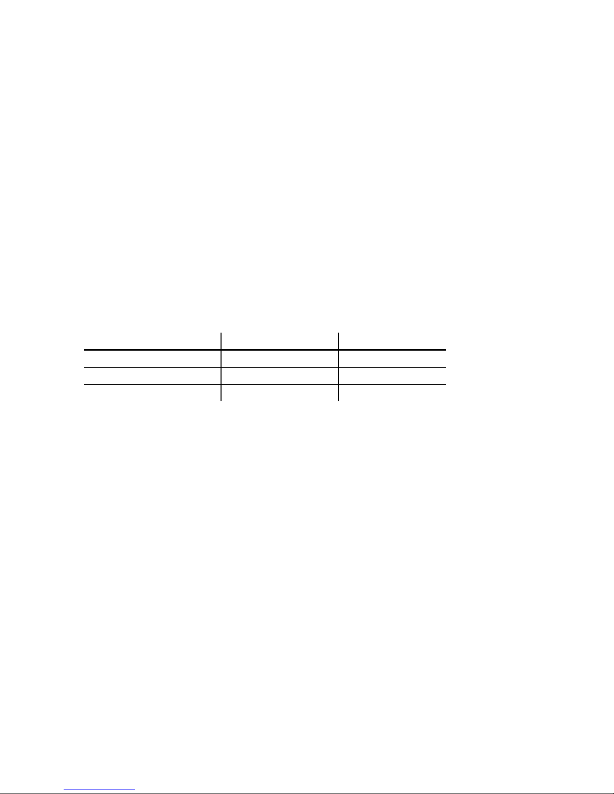
Option Set using Default
PC/104 bus I/O Address switch bank S1, 1-4 340 (hex)
PC/104 bus IRQ # switch bank S1, 5-8 IRQ disabled
Host interface mode jumper JP7 PC/104 bus
Table 1-1. PC/104 motion controller board default settings.
The host interface mode jumpers will not need to be changed unless it is desired that the
card be operated in serial mode. If operated in serial mode, a special adapter board is
required.
The following diagram shows the location of the jumper JP7:
8
Page 9
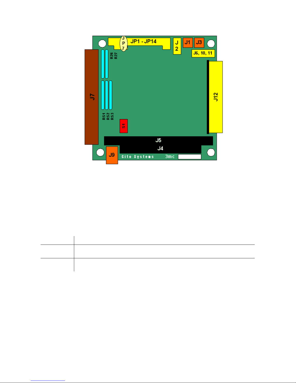
Figure 1-1. Settable jumpers and connectors
If you need to change the default setting values from the Table 1-1, or are not sure if they
need to be changed, the following sections explain more about these settings.
1.4.1. Setting the Host I/O Mode
The PC/104 motion controller supports two different communication modes. This is shown
in the following table:
Mode Description
PC/104
mode
The motion processor accepts instructions and data as full 16-bit words, using
the entire 16-bit data path
Serial port The motion processor accepts instructions through an asynchronous serial
port.
The figure below shows how the JP7 jumper should be installed to select the host mode.
PC/104 mode is the default. Shading indicates the location of the jumper.
9
Page 10
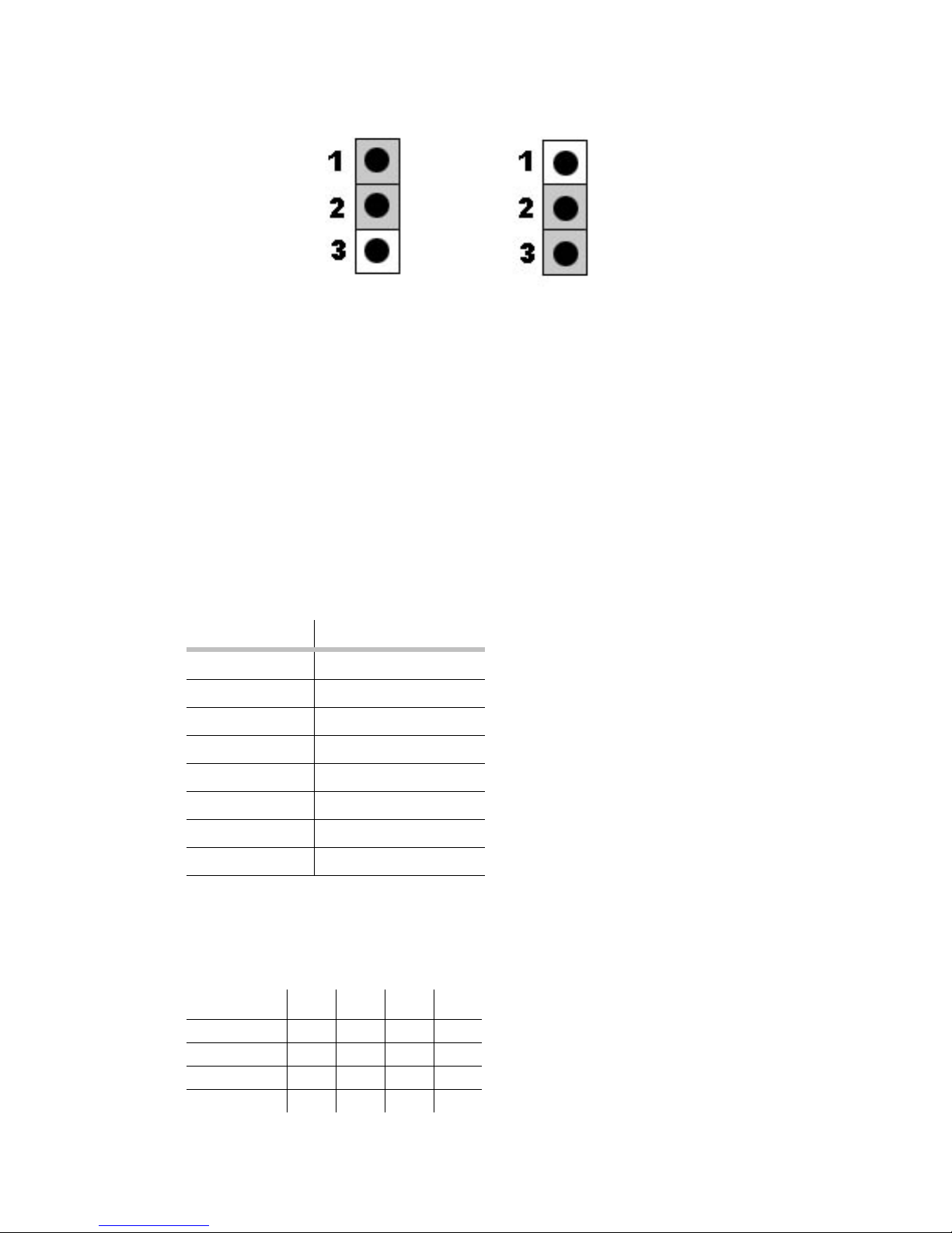
serial port PC/104 parallel
1.4.2. Setting the PC/104 bus I/O address
The PC/104 motion card occupies 16 consecutive I/O addresses on the PC/104 bus,
starting at the "base address", and ending at the base address+F (hex). For example for the
default base address, which is 340 (hex), the total used range of addresses is 340 (hex) – 34F
(hex).
The I/O port base address should be chosen so that it doesn’t conflict with any other
devices using addresses in the range 300h-3FFh. Certain of these addresses are reserved for
specific peripherals, as shown in the following table (not all will be present in a given
system):
Port address Device
300-377h available
378-37Fh LPT1
380-3Afh usually available
3B0-3DFh VGA
3E0-3E7h available
3E8-3Efh COM3
3F0-3F7h Hard disk controller
3F8-3FFh COM1
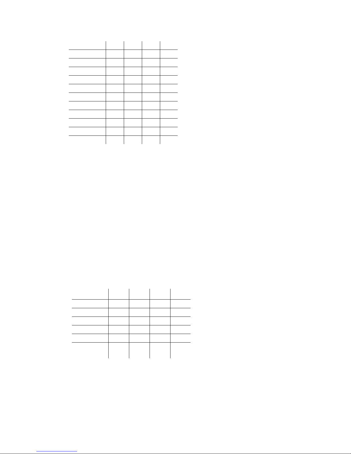
Switch block S1, switches 1 - 4 determine the PC/104 bus base address. In the table below
switches, which should be on are indicated as such. A blank space in the table indicates the
switch should be set off (or left).
Address S1-1 S1-2 S1-3 S1-4
300h
310h
320h
330h
on on on on
on on on
on on on
on on
10
Page 11
340h
350h
360h
370h
380h
390h
3A0h
3B0h
3C0h
3D0h
3E0h
3F0h
on on on
on on
on on
on
on on on
on on
on on
on
on on
on
on
The default I/O port address is 340 hex (1-4: on, on, off, on)
For more detailed info on the I/O addresses used by the motion controller board, see
Appendix A, "PC/104 Motion Controller Electrical Reference", section 5.1.3.6.
1.4.3. Setting the IRQ level
The PC/104 controller board allows the motion chipset's HostIntrpt signal (used by the
chipset to signal special events) to generate a PC/104 interrupt that can be processed by
interrupt handling routines in the PC/104-based control software. The specific interrupt
(IRQ) that is generated can be programmed on the Millennium board using S1 switches #5-
8. The PC interrupt is generated when the chipset's HostIntrpt signal transitions from high
to low.
The table below shows the IRQs that are selectable and the associated S1 switch settings. If
no IRQ generation is desired than the "IRQ disabled" option should be selected. A blank
space in the table indicates the switch should be off (down).
IRQ # S1-5 S1-6 S1-7 S1-8
3
5
7
10
11
IRQ
on on on on
on on on
on on on
on on
on on on
disabled
The default IRQ setting is "IRQ disabled"
11
Page 12
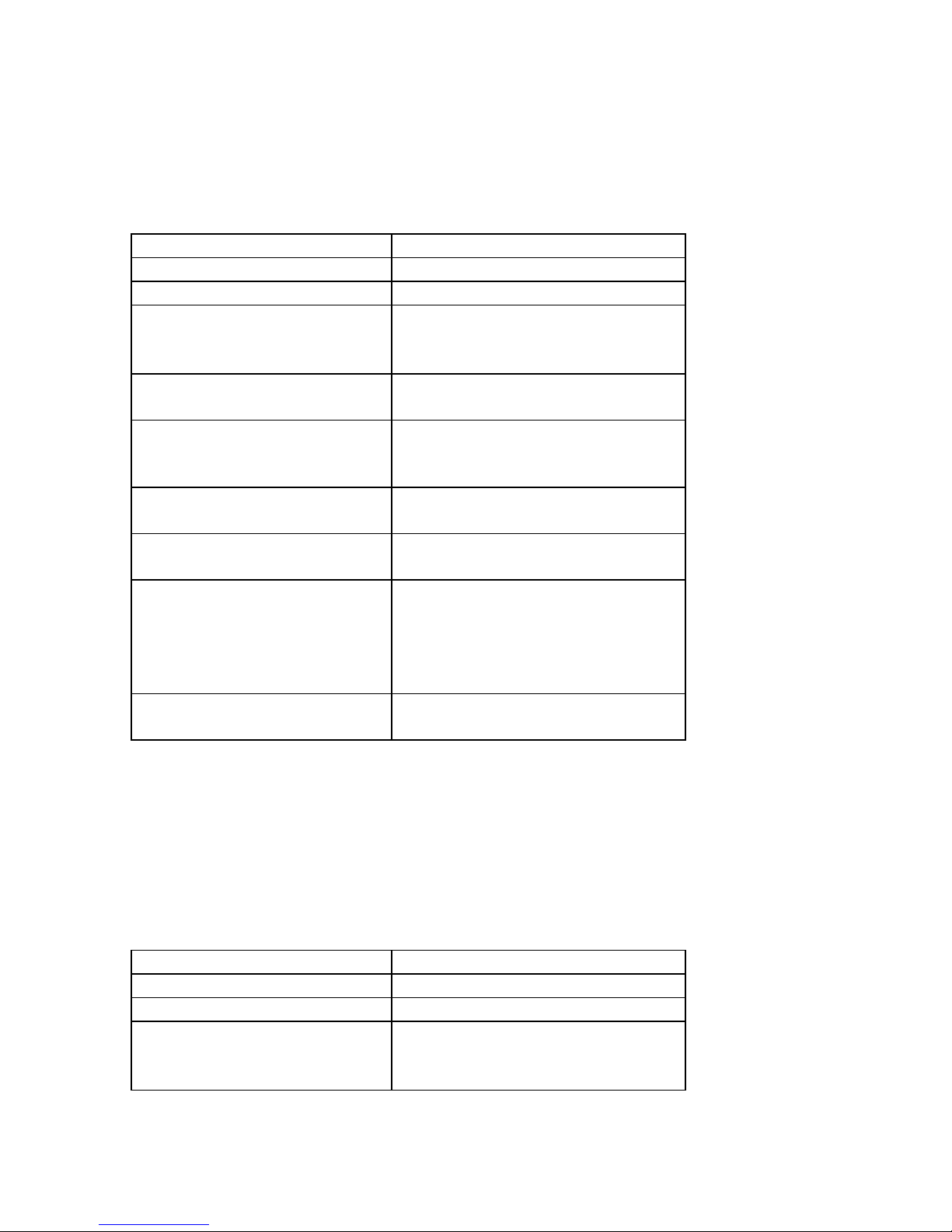
1.5 3mc-0x-Bx Connections Summary
The following table summarizes the connections provided and expected by the Millennium
PC/104 board when a MC2140 chipset is installed. Although the MC2140 supports up to
four axes any number of axis between 1 and 4 may be connected.
Chipset: MC2100 series
Maximum # of Axes: 4
Encoder Input Type: Incremental encoder
Encoder Input Signals:
(per axis)
# motor output channels:
(per axis)
Amplifier Output Signals
(per axis, if PWM sign,
magnitude used)
Amplifier Output Signals
(per axis, if PWM 50/50 used)
Amplifier Output Signals
(per axis, if analog output used)
Other Control Signals:
(per axis)
Miscellaneous Signals: GND
A quadrature channel input
B quadrature channel input
Index pulse channel input
1
PWM Direction
PWM magnitude
PWM magnitude
Differential analog out (DAC output)
Home signal channel input
Positive limit switch input
Negative limit switch input
Fault input
AxisOut output
+5 V (for encoder power)
For a complete description of the PC/104 card connectors and interfacing
requirements see Appendix A "PC/104 Motion Controller Electrical Reference".
1.6 3mc-0x-BLx Connections Summary
The following table summarizes the connections provided and expected by the Millennium
PC/104 board when a MC2340 chipset is installed. Although the MC2340 supports up to
four axes any number of axis between 1 and 4 may be connected.
Chipset: MC2300 series
Maximum # of Axes: 4
Encoder Input Type: Incremental encoder
Encoder Input Signals:
(per axis)
A quadrature channel input
B quadrature channel input
Index pulse channel input
12
Page 13
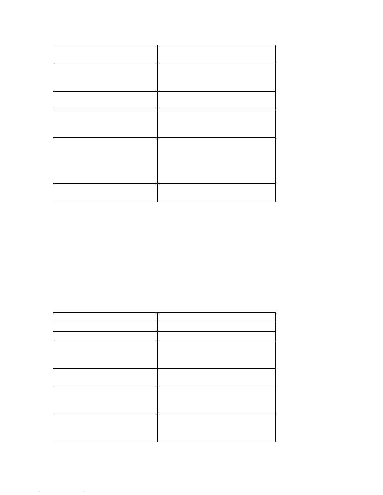
# motor output channels:
(per axis)
Amplifier Output Signals
(per axis, if PWM 50/50 used)
2 or 3 depending on motor output
selected and # phases
PWM magnitude (phase A)
PWM magnitude (phase B)
PWM magnitude (phase C)
Amplifier Output Signals
(per axis, if analog output used)
Analog out (phase A)
Analog out (phase B)
Hall inputs: Hall (phase A)
Hall (phase B)
Hall (phase C)
Other Control Signals:
(per axis)
Home signal channel input
Positive limit switch input
Negative limit switch input
Fault input
AxisOut output
Miscellaneous Signals: GND
+5 V (for encoder power)
For a complete description of the PC/104 card connectors and interfacing
requirements see Appendix A "PC/104 Motion Controller Electrical Reference".
1.7 3mc-0x-B/BLx Connections Summary
The following table summarizes the connections provided and expected by the Millennium
PC/104 board when a MC2840 chipset is installed. Although the MC2840 supports up to
four axes any number of axis between 1 and 4 may be connected. Since this chipset allows
controlling a combination of brush and brushless servomotors, two pairs of each motor type
can be used.
Chipset: MC2800 series
Maximum # of Axes: 4
Encoder Input Type: Incremental encoder
Encoder Input Signals:
(per axis)
# motor output channels:
(per axis)
Amplifier Output Signals
(per axis, if PWM sign,
magnitude used)
Amplifier Output Signals
(per axis, if PWM 50/50 used)
A quadrature channel input
B quadrature channel input
Index pulse channel input
1, 2 or 3 depending on motor output
selected and # phases
PWM Direction
PWM magnitude
PWM magnitude (phase A)
PWM magnitude (phase B)
PWM magnitude (phase C)
13
Page 14
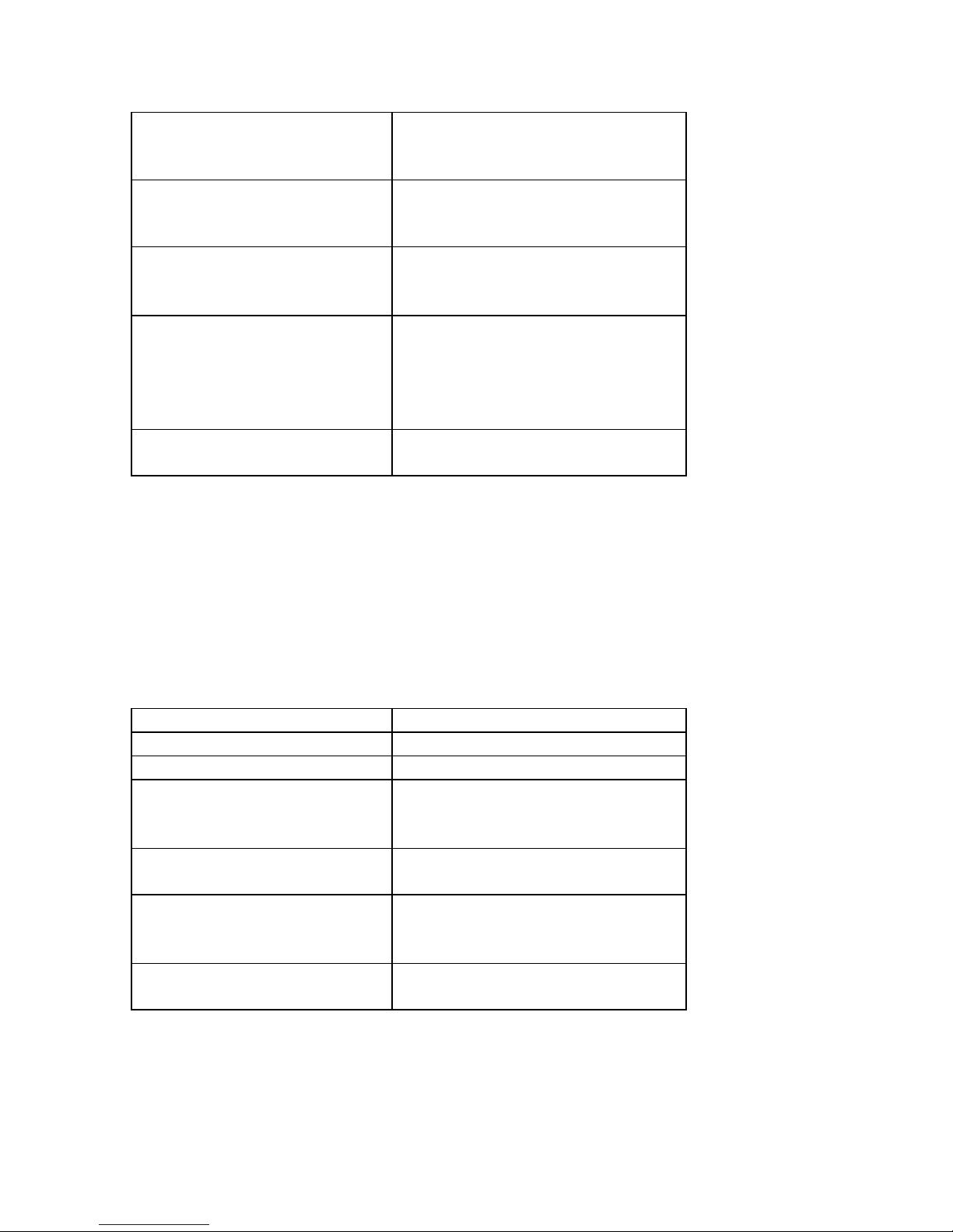
Amplifier Output Signals for
Differential analog out (DAC output)
brush type motors
(per axis, if analog output used)
Amplifier Output Signals for
brushless type motors
Analog out (phase A)
Analog out (phase B)
(per axis, if analog output used)
Hall inputs: Hall (phase A)
Hall (phase B)
Hall (phase C)
Other Control Signals:
(per axis)
Home signal channel input
Positive limit switch input
Negative limit switch input
Fault input
AxisOut output
Miscellaneous Signals: GND
+5 V (for encoder power)
For a complete description of the PC/104 card connectors and interfacing
requirements see Appendix A "PC/104 Motion Controller Electrical Reference".
1.8 3mc-0x-MSx Connections Summary
The following table summarizes the connections provided and expected by the Millennium
PC/104 board when a MC2440 chipset is installed. Although the MC2440 supports up to
four axes any number of axis between 1 and 4 may be connected.
Chipset: MC2400 series
Maximum # of Axes: 4
Encoder Input Type: Incremental encoder
Encoder Input Signals:
(per axis)
# motor output channels:
(per axis)
Amplifier Output Signals
(per axis, if PWM 50/50 used)
Amplifier Output Signals
(per axis, if analog output used)
A quadrature channel input
B quadrature channel input
Index pulse channel input
2 or 3 depending on motor output
selected and # phases
PWM magnitude (phase A)
PWM magnitude (phase B)
PWM magnitude (phase C)
Analog out (phase A)
Analog out (phase B)
14
Page 15
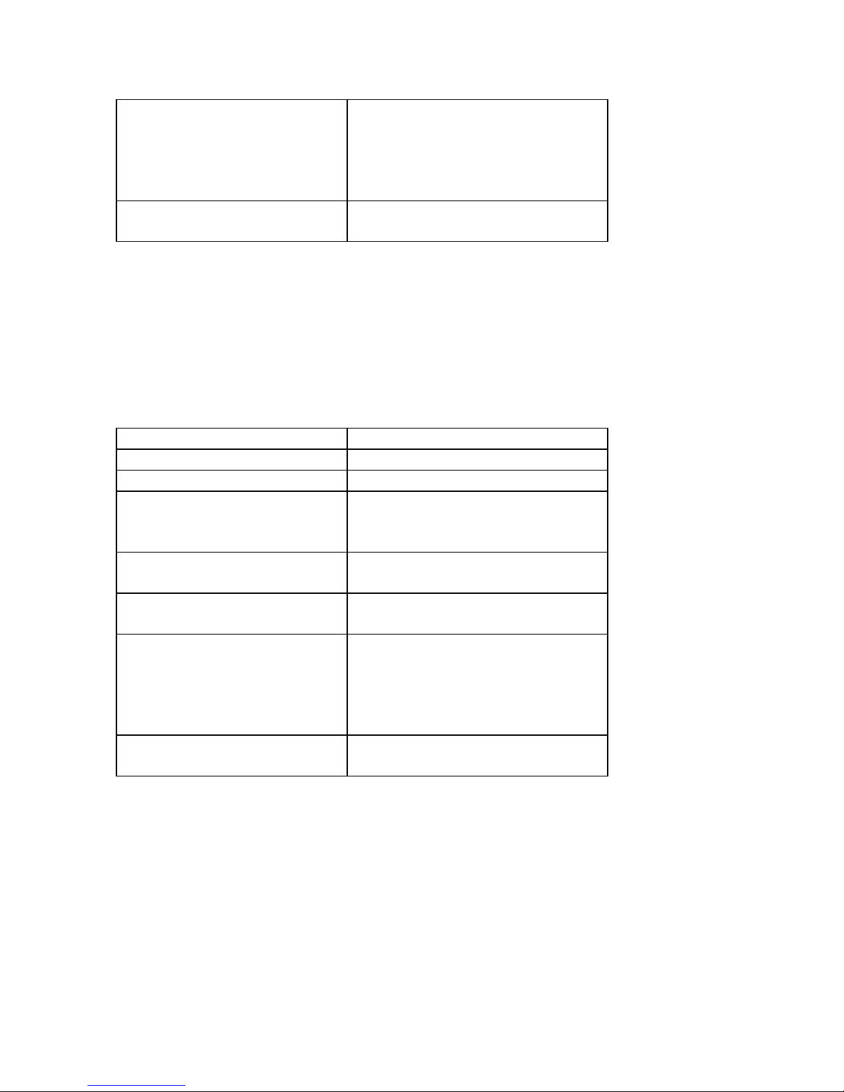
Other Control Signals:
(per axis)
Home signal channel input
Positive limit switch input
Negative limit switch input
Fault input
AxisOut output
Miscellaneous Signals: GND
+5 V (for encoder power)
For a complete description of the PC/104 card connectors and interfacing
requirements see Appendix A "PC/104 Motion Controller Electrical Reference".
1.9 3mc-0x-S Connections Summary
The following table summarizes the connections provided and expected by the Millennium
PC/104 board when a MC2540 chipset is installed. Although the MC2540 supports up to
four axes any number of axis between 1 and 4 may be connected.
Chipset: MC2500 series
Maximum # of Axes: 4
Encoder Input Type: Incremental encoder
Encoder Input Signals:
(per axis)
# motor output channels:
(per axis)
Amplifier Output Signals:
(per axis)
Other Control Signals:
(per axis)
Miscellaneous Signals: GND
A quadrature channel input
B quadrature channel input
Index pulse channel input
1
Pulse
Direction
Home signal channel input
Positive limit switch input
Negative limit switch input
Fault input
AxisOut output
+5 V (for encoder power)
For a complete description of the PC/104 card connectors and interfacing
requirements see Appendix A "PC/104 Motion Controller Electrical Reference".
1.10 Applying Power
Once you have connected the board to the desired number of external amplifiers and motor
encoders, hardware installation is complete and the board is ready for operation.
Upon power up, the motion controller will be in a reset condition. In this condition no
motor output will be applied until the chipset is initialized (see next section on software for
15
Page 16

details). Therefore, the motors should remain stationary. If the motors do move or jump,
power down the board and check the amplifier and encoder connections. If anomalous
behavior is still observed, call Cito Systems, or your local representative for assistance.
2 Software Installation
On the storage media (CD) provided with the Millennium series PC/104 motion
controller there is a motion functions library called C-MotionPlus. This library contains
functions that are commands for the motion processor installed in the controller. The
user is responsible for writing a program to control motors motion and serving specific
application. In the following sections [2.2.1. – 2.2.5] are samples of the functions to
perform some basic moves.
The C-MotionPlus software library provided by Cito Systems supersedes the C-Motion
supporting the Navigator motion processors. C-MotionPlus provides interfaces to the C
functions as well as to the methods of C++ classes. It also has an interface to the TCL
scripting language. Additionally, this library allows communicating with multiple car ds
on the bus at the time and invoking directly from a terminal window all the functions on a
local computer or remote one via network or RS-232/RS-485 link. The library supports
functions specific to Millennium series motion control boards.
It can be used in the Windows and Linux operating systems environment.
2.1 Using EasyMotion Console
EasyMotion is an application software package that can be purchased from Cito Systems for
easy and fast setting of a motion system. It contains a set of tools that help and assist in
configuring the motion card. One of the tools is a Motion Console that works as a terminal
interface allowing direct calling of the C-MotionPlus library functions. This way, without
writing a single line of code one can talk to the board and quickly verify the system.
16
Page 17
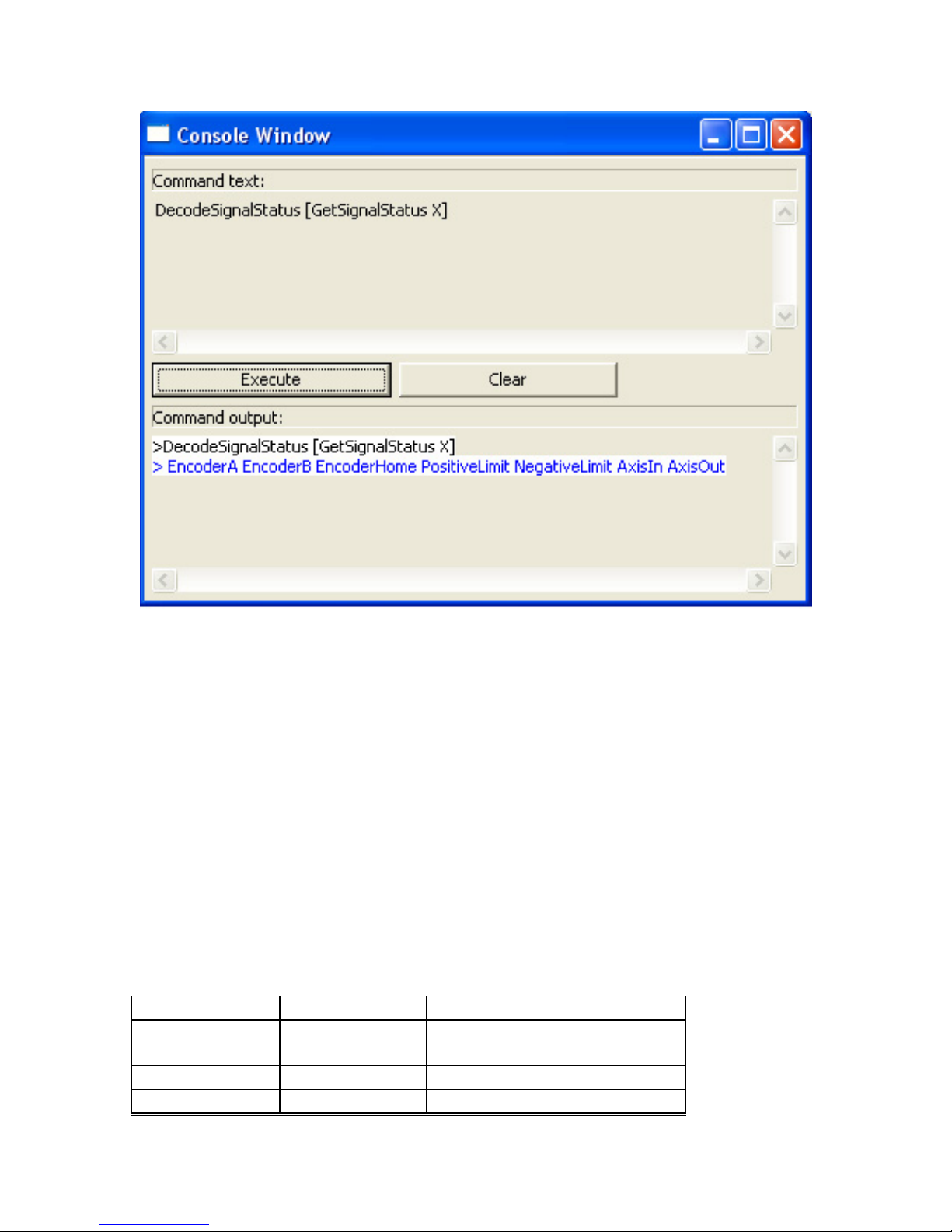
Figure 2-1. Motion Console - EasyMotion command interface
2.2 First Time System Verification
To verify that the Millennium board has been properly installed, it is useful to have each axis
of the system perform a short move.
For the MC2100 parts to perform this simple sequence it is necessary to specify two items:
• the motor amplifier type (PWM sign/mag, PWM 50/50, or analog)
• the filter gains
For the MC2300 parts it is necessary to specify these two items as well as to initialize the
motor commutation.
The following table summarizes this. Note that the step #'s reference specific steps, which
are detailed in the next section.
Chipset Step # Operation
MC2100 1
4 Set filter parameters
5 Make a trajectory move
Set amplifier type (PWM
sign/mag, PWM 50/50, DAC)
17
Page 18
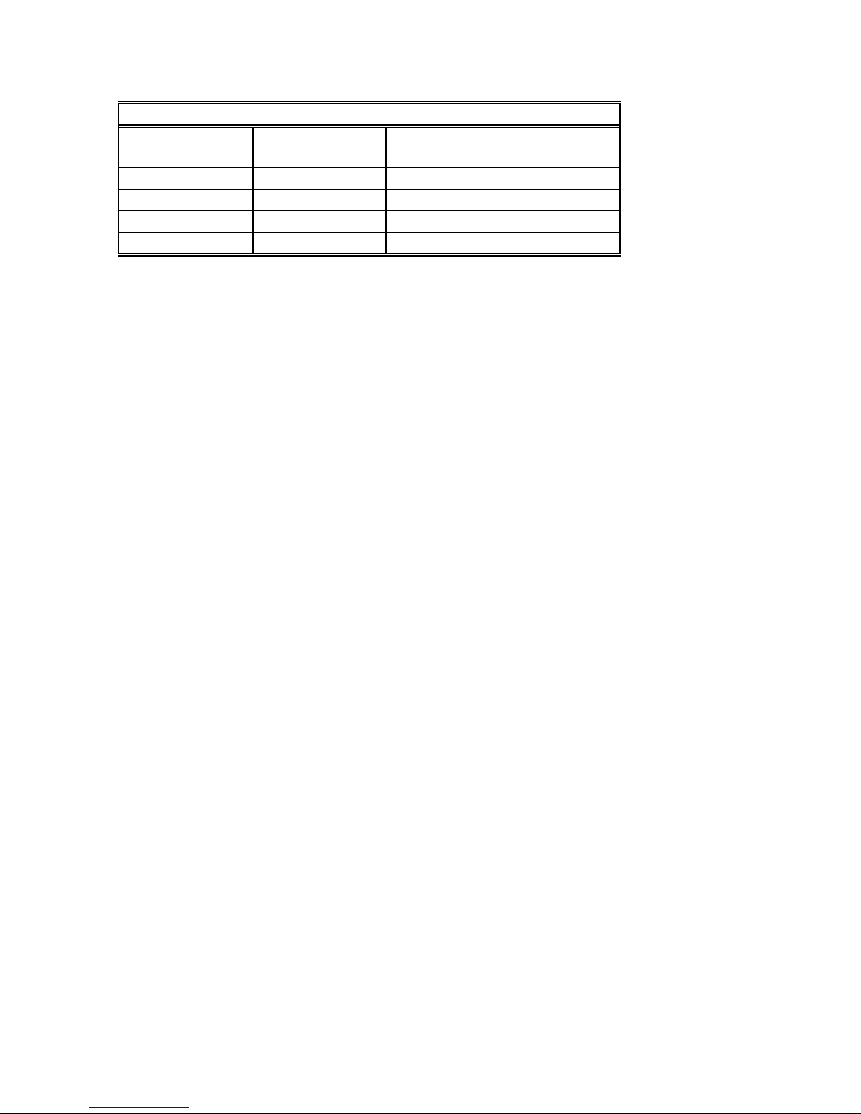
MC2300 1
Set amplifier type (PWM 50/50,
DAC)
2 Initialize commutation
3 Check Commutation
4 Set filter parameters
5 Make a trajectory move
Only perform the setup step sequences indicated above for the chipset installed on your board.
To start verification use the following Navigator commands
SetActualPosition 0
Update
SetKp 25
Refer to the “Programmers Reference Manual” for a full list of commands.
It is assumed that you will check out each axis of your system one at a time. Then to check
out other axes enter a new axis number and check that axis out entirely, etc.
2.2.1. Step #1 Set the Motor Amplifier Type
The card must be told what type of motor output mode to use, PWM sign/mag, PWM
50/50, or DAC. This can be set using the command SetOutputMode. Assuming the axis you
want to exercise is #1, you would use the command "SetOutputMode" followed by the
output mode: 0 for DAC, 1 for PWM sign/mag, and 2 for PWM 50/50. For example to
specifiy the output mode as PWM 50/50 the following command would be used:
SetOutputMode 2
2.2.2. Step #2 Initialize Commutation
Note: This sections applies to MC2300 and MC2800 chipsets only.
For the motor to be controlled properly using the MC2300, the chipset must select and
possibly initialize the commutation phasing. If you will be using Hall-based commutation
then no initialization is necessary. Simply specify this to the chipset using the command:
SetCommutationMode 1
No other commands are necessary and you may proceed to step #3.
If you will be commutating using a sinusoidal technique you must initialize the commutation
phasing. There are two ways this can be done. You will need to decide whether to initialize
using Hall-based or algorithmic methods. See the Navigator User's Guide for more
information on this.
Each of these two phase initialization methods requires a separate sequence, as follows (note
that // indicates a comment and should not be typed in):
Hall-based initialization command sequence:
SetPhaseInitializeMode 1 // set phase initialize mode to 'Hall-based'
SetNumberPhases x // where x is 2 or 3 depending on type of motor
InitPhase
18
Page 19

Algorithmic-based initialization command sequence:
SetPhaseInitializeMode 0 // set phase initialize mode to 'algorithmic'
SetMotorMode 0 // places axis in open loop mode, required for algorithmic init.
SetNumberPhases x // x is 2 or 3 depending on type of motor
SetPhaseCounts yyyy // yyyy is # of encoder counts per elec. cycle
SetPhaseInitializeTime zzzz // zzzz is # of chipset cycles to initialize for
SetMotorCommand wwww // wwww is motor command.
InitPhase
To determine the values of x, yyyy, zzzz, and wwww you should refer to the Navigator
User's Guide, "commutation" section.
If your system has one or more of the following conditions present then the above
sequence will need to be expanded. To handle such systems you will need to use the
SetSignalSense command as well as the SetPhasePrescale command. Call Cito
Systems for assistance
1) One or more Hall signals must be inverted to commutate or initialize the
commutation correctly
2) # of encoder counts per electrical cycle exceeds 32,767
2.2.3. Step #3 Check Commutation
Note: This sections applies to MC2300 and MC2800 chipsets only.
After phase initialization has been completed it is useful to check the smoothness of the
motor rotation in open loop mode to verify that the motor phasing initialization and
commutation is correct. To do this use the following command sequence:
SetMotorMode 0 // set axis for open loop operation
SetMotorCommand xxxx // xxxx is the motor command from 0 to 32,767 to output
Update
The 'xxxx' value represents the fraction of the value 32,768 of total power that will be
applied to the motor. For example, a value of 1,000 sends roughly 3% of the total power to
the motor.
When the motor mode is set off, the motor is not under servo control. Beware that
the motor may spin rapidly after a motor command value is applied. Use small values
and increase slowly.
After this command sequence the motor should smoothly spin in one direction or the other.
The motor command is a signed number and the sign controls the rotation direction. When
a positive motor command is given the motor should rotate in the positive (increasing
encoder counts) direction. If the motor spins roughly, in the wrong direction, or if it moves
a short distance and then abruptly stops there may be a problem with the commutation.
Check your wiring and re-test. Once the motor is spinning smoothly in both directions
19
Page 20

under open loop control re-enable closed-loop servo control by executing the following
command:
SetMotorMode 1
2.2.4. Step #4 Set Filter Parameters
For motion to occur, some amount of feedback gain must be specified. Initially use just a
proportional gain with a very low value between 1 and 25. Later you can add integral or
derivative gains as well as feedforward gains if desired. The following sequence shows how
to set the P, I, and D terms of the filter and how to 'update' them, making them active.
SetKp xxxx // xxxx is the desired proportional gain
SetKd yyyy // yyyy is the desired derivative gain
SetKi zzzz // zzzz is the desired integral gain
Update // make thee values active.
It is not necessary to specify all 3 gains. Just Kp, followed by an Update can be specified, just
a Kd, etc...
Important note:
When exercising the motor use extreme caution. It is the responsibility of the
user to observe safety precautions at all times.
2.2.5. Step #5 Make a Trajectory Move
To test that the motor is being driven properly, set up and execute a small trapezoidal move.
Specify a small distance of (for example) 5,000 counts, and a low velocity and acceleration of
(for example) 10,000 counts/sample time, and 10 counts/sample time2 respectively. With a
cycle time of 400 µsec, these values correspond to roughly 381 counts/sec, and 954
counts/sec2, respectively.
Whatever profile values you use, be sure that they are safe for your system.
Here is the command sequence to use:
SetProfileMode 0 // Sets current profile mode to trapezoidal
SetPosition xxxx // xxxx is the desired destination position
SetVelocity yyyy // yyyy is the desired maximum velocity
SetAcceleration zzzz // zzzz is the desired acceleration
SetDeceleration wwww // wwww is the desired deceleration
Update // execute the move
After entering this sequence of commands you should see the axis smoothly move for about
15 seconds (if the suggested values are used and the cycle time of the chipset is 400 µsec). If
you do not see the axis moving, or if the axis jumps rapidly in one direction or the other,
there may be a problem with the board or software settings. Re-check and review the board
setup procedures, as well as the exerciser parameter settings.
20
Page 21

If you are still having problems after re-checking your system call your Cito Systems
representative.
3 Operation
3.1 Card overview
The PC/104 motion controller harnesses the power of a dedicated DSP motion processor,
which calculates the servo filter algorithm, generates the trajectory profile and handles
some I/Os. It works along with the ASIC chip that conditions encoder feedback signals,
generates the PWM output and handles the parallel communication with the host. The
motion processor incorporates an advanced PID filter with velocity and acceleration
feedforward terms.
The DSP processor is supported by an on-board dual-port RAM. The DP RAM can be
utilized as a data trace to capture on-the-fly various parameters or as a fast data exchange
buffer between the board and the host.
The motion control card implements the open architecture concept that allows for an easy
way to satisfy specific customer needs. Most of the applications, however, fit in the
standard board design that features powerful set of I/Os. Besides dedicated opto-isolated
I/Os for motion tasks, the board has a set of general purpose digital I/Os, the board has a
set of general purpose digital I/Os. The TTL level outputs are paralleled with a driver that
allows controlling power demanding peripheral devices. In addition, there is a set of
analog inputs. Motor drives can be interfaced with differential signals enhancing
immunity to electrical noise. The board has built-in features that make easy
implementation of sophisticated safety and fault handling schemes. The design
eliminates need for additional daughter boards, thus enabling extremely compact and
versatile control systems integration.
21
Page 22
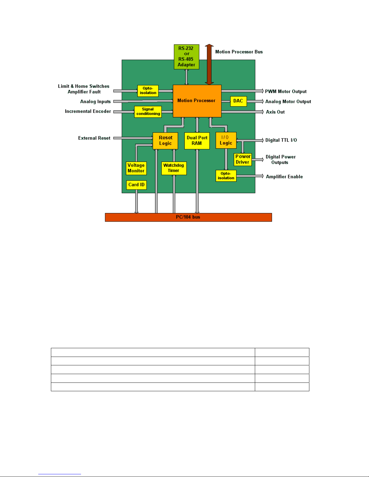
Figure 3-1. PC/104 motion controller block diagram
3.2 Dual-port RAM
To enhance the card performance, the dual-port RAM capability has been implemented
for fast data exchange with the host. It allows direct data flow from and to the host,
bypassing the card’s motion processor. The DP RAM can be accessed through
automatically incremented addressing (auto-incremental mode), which is faster than the
non-incremental mode, in which the memory address has to be specified each time being
accessed.
The dual port RAM can operate in 4 different modes, which are listed in the table below.
They can be set through CMSetMemoryMode() command from the C-MotionPlus library.
Writing and reading to the memory is done through respectively CMWriteMemory() and
CMReadMemory().
Access operation Parameter value
Non-incremental writing and reading to/from the memory 0
Auto-incremental, for only reading from the memory 1
Auto-incremental, for only writing to the memory 2
Auto-incremental, for writing and reading to/from the memory 3
3.3 Safety Features
The PC/104 motion card design accommodates a set of features that can be utilized in
developing safety and fault handling schemes. In the event, external or internal erroneous
22
Page 23

conditions occur, the board settings could be brought to their default state. The most
important purpose of these features is to insure the moving motors to a safe stop.
3.3.1. Hard Reset
The hard reset generates a signal that causes the board to go into an initial state as when it
is powered up. The processor reinitializes itself bringing all settings to the default values
and the card circuitry is set to its initial state. It means that motor command outputs are
set to zero forcing the motors to a safe stop. The hard reset is executed by the CMotionPlus command - CMHardReset().
3.3.2. Soft Reset
The board can perform a soft reset command. The soft reset, executed by PMDReset()
command from the C-MotionPlus library, changes all motion processor settings to their
default values and does not affect other circuitry on the board like the general purpose
I/Os, memory content and reset status monitor. This command sets motor output signals
to zero thus bringing the motors to a safe stop.
For the motion processor default values refer to the “Programmer’s Reference Manual”.
3.3.3. External Reset
The card provides an input at the pin 43 of the J12 connector to interface the external
reset signal, which can be generated by a switch or an electronic circuit. The reset is
triggered by an active-low TTL compatible logic for a minimum duration of 1 ms. The
reset input employs an internal pull-up resistor.
3.3.4. Under Voltage Monitor
An under voltage monitor circuit contributes to the overall system safety scheme. It
detects power supply voltage drop below level of 4.625V and, should it happened,
generates the hard reset signal to the processor. The reset causes the motor command
outputs to be set to zero bringing the motors to a safe stop and all the board settings to the
default values.
3.3.5. Watchdog Timer
The watchdog timer is a dedicated 4-bit write only register that serves system safety
functionality. It generates the hard reset signal in the event of disrupted communication
between the motion card and the host lasting more than the specified period of time. The
reset causes the motor command outputs to be set to zero bringing the motors to a safe
stop and all the board settings to the default values.
A dedicated C-MotionPlus library function CMSetWatchdog() enables the watchdog
timer when it is called for the first time. The default state of the watchdog timer is
disabled, thus long as no call to this function happens the watchdog remains inactive. A
parameter to the function specifies the watchdog sleep phase, which falls in a range of 1393 msec. Repeatable calling this function within the specified time period prevents the
processor from being reset and keeps it in normal working condition. Once this period is
exceeded and no function call happens, the reset event will occur
23
Page 24
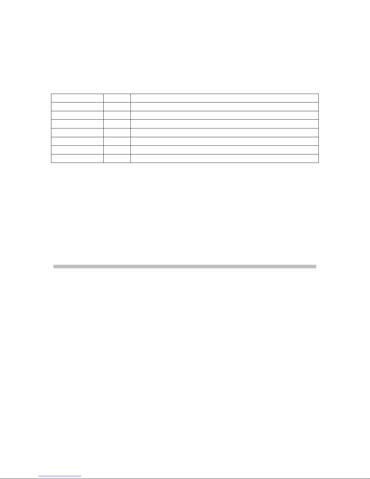
3.3.6. Reset Status Monitor
All the reset sources can be monitored via the reset status register. The
CMGetResetStatus() command from the C-MotionPlus library reads the register’s
content. The below table list the encoding of the data returned by this command.
Reset source Bits Description
Reserved
Soft reset 8 Set to 1 when Reset() command was executed
External reset 9 Set to 1 when external signal at J12 pin 43 was brought to low
Under voltage 10 Set to 1 when power supply voltage dropped below 4.625V
Watchdog 11 Set to 1 when watchdog time out occured
Hard reset 12 Set to 1 when HardReset command was executed
Reserved
After the reset signal has been detected and its source identify from the reset status
register through CMGetResetStatus() command, the content of the reset status register
can be cleared. This way the register bits are refreshed to capture new reset conditions.
0..7 Not used, may be 0 or 1
13..15 Always set to 0
3.4 Card ID Number
Each card has its own identification number coded. To query the board for its ID number,
the CMGetCardID() function from the C-MotionPlus library should used.
4 Connecting Hardware
This section explains how to connect external components to the Millennium PC/104
motion control card. It assists the motion system designers in integrating the card to their
designs.
4.1 Motor Output Command Signals
The Millennium series controllers can control, depending on the card model, servo brush,
servo brushless, stepper and micro-stepping motors. The following sections describe
motor output command signals that control each motor type.
4.1.1. Analog Output Motor Command
For motor amplifiers that take an analog control signal and drive servo or microstepping
motors, this group of motor command signals should be used. This output provides
analog voltage in the –10V - +10V range and can used as the single-ended or differential
analog signal in case of non-phased motion processor MC21xx.
The analog output mode of operation can be set ing PMDSetOutputMode() command
from the C-MotionPlus library.
24
Page 25

Section 5.2 Appendix B. Outputs to Motor Amplifiers in this manual describes in detail
connections to motor amplifiers, depending on a motor type and its phase number.
4.1.2. PWM Output Motor Command
This set of motor command signals is being used to control servo or microstepping
motors and very well suits purpose of simple structure motor amplifiers. The PWM
(Pulse With Modulation) output can be configured as Sign/Magnitude or 50/50 mode
using PMDSetOutputMode() command from the C-MotionPlus library.
Section 5.2 Appendix B. Outputs to Motor Amplifiers in this manual describes in detail
connections to motor amplifiers, depending on a motor type and its phase number.
4.1.3. Pulse and Direction Output Motor Command
These motor command output signals are compatible with standard amplifies that drive
stepper motors. The Pulse signal is a pulse train that controls motor velocity, while the
Direction signal, which can be set as low or high, determines in which direction the
motor rotates.
4.2 Incremental Encoder
The incremental encoder signals QuadA, QuadB and Index provide position feedback
information to the motion processor. They are necessary to close the position loop in
servo system applications for DC brush or DC brushless servomotors, continuously
tracking motor shaft position. In case of stepper and microstepper motors they can be
used as optional source of information to verify a motor shaft position at the move end to
eventually compensate for lost steps.
The encoder signals can be configured as single-ended or differential. The single-ended
configuration should be used in an electrical noise-free environment and short wire length
up to 3m (10ft). It requires only one set of signals to be connected i.e. QuadA+, QuadB+
and Index+, the JP8-JP11 jumpers set to the position 2-3 and the RS1-RS3 resistor packs
removed. The differential encoder configuration uses long line drivers and requires all
encoder signals to be connected – QuadA+, QuadA-, QuadB+, QuadB-, Index+ and
Index-, the JP8-JP11 jumpers installed at the position 1-2 and the RS1-RS3 resistor packs
installed on the cards.
4.3 Parallel Feedback Devices
The PC/104 board is capable of handling feedback information from parallel devices, like
absolute encoders and laser interferometers. Since these devices vary from one
manufacturer to another, a dedicated adapter board has to be designed to interface to a
specific device. Cito Systems provides design resources upon customer request.
4.4 Home and Limit Switches
The card has a group of dedicated input signals that interface to the motion processor.
The Positive and Negative Limits are assigned to each axis to prevent motors from over
running its travel limits. They can be programmed as active high or low. When the
25
Page 26

motion processor senses their active state, it abruptly stops further motor motion in that
direction. The reverse motion is possible in order to deactivate the limit signal.
The Home signal is assigned to each axis and is dedicated to its homing function. It can
be programmed as active high or low and is used in various homing schemes.
Check “The EasyMotion User’s Manual” and “The Navigator’s Processor User Guide”
for a detail description of these signals functionality.
For board’s processor safety and noise immunity these signals are opto-isolated. See fig.
3.1 for the electrical interface to these signals.
In the environment, where electrical noise is not a concern and there is no external power
supply available to power Home and Limit switches signals, opto-isolation can be
defeated by connecting the board’s digital ground with the Opto ground. In order to that,
jumpers JP12 and JP13 should be installed. These jumpers also defeat the Amp Fault
signal opto-isolation.
4.5 Amplifier Enable Outputs
The Amp Enable1-4 signals provide opto-isolated digital output for each axis to enable
motor amplifiers. They are controlled through CMAmpEnable(), a C-MotionPlus library
function.
These signals, if not used for the amplifier enable function, can be used as general
purpose digital outputs. To ensure boards reliability and noise immunity these signals are
opto-coupler driven.
In the environment, where electrical noise is not a concern and there is no external power
supply available to power Amp Enable signal, opto-isolation can be defeated by
connecting the board’s digital ground with the Amp Enable signal ground. In order to
that, jumpers JP16 and JP17 should be installed.
4.6 Amplifier Fault Inputs
The Amp Fault 1-4 signals provide opto-isolated digital inputs, one per axis, from motor
amplifiers. This is a direct feedback to the motion card from the amps about their
malfunction status. The current status of motor amps can be monitored using the
CMGetAmpFault() function from the C-MotionPlus library.
If these inputs are not attached to the motor amplifiers they can be used as general
purpose inputs. To ensure boards reliability and noise immunity these signals are optocoupler driven.
In the environment, where electrical noise is not a concern and there is no external power
supply available to power Amp Fault signal, opto-isolation can be defeated by connecting
the board’s digital ground with the Opto ground. In order to that, jumpers JP12 and JP13
26
Page 27

should be installed. These jumpers also defeat the Home and Limit switches signals optoisolation.
4.7 Axis Out Signal
The Axis Out Signal lines, one per each axis, serve as an external monitoring signals of
the Event Status, Activity Status or Signal Status registers bits. They can be used as
trigger signals for external devices.
The status register and its monitored bit can be selected using PMDSetAxisOutSource()
command from the C-MotionPlus library. For detail description of this function see “The
Programer’s Reference Manual”.
4.8 General Purpose Digital I/Os
The board features 8 input and 8 output general purpose TTL level signals. They can be
expanded up to 128 inputs or 128 outputs with an additional circuitry. The outputs are
configured as totem poles and can interface to CMOS or bipolar external circuits being
capable to source/sink up to 20 mA current.
4.8.1. High power digital I/Os
The 8 digital output signals are interfaced through opto-couplers to high power drivers
providing control signals for devices that drive higher current at higher voltage than just
the TTL devices are capable of. Since there is no need for additional interface driver
boards, a highly compact control system can be assembled capable of controlling LEDs,
lamps, relays or other devices requiring power control signals.
The high power signals can be configured as current sink or current source devices.
When all 8 outputs are turned on, they can continuously provide up to 300 mA current at
+24 V supply. Maximum driver rating allows for current not exceeding 500 mA at +50V,
when outputs are working in a switching cycle mode. For specifics see technical notes of
ULN2803 and UDN2982 devices.
Important note:
The power output drivers interface 8 TTL level digital outputs, what means
that they have the same logic control. One cannot assume them as being
additional signals to the 8 general purpose TTL outputs (see figs. 5.3 and
5.4.).
4.9 Analog Inputs
The board features 8 analog inputs working in 0 – 5V range with 10-bit resolution. The
analog-to-digital converters can be configured in 2 different reference voltage modes
using the JP1-JP4 jumper set. When jumpers are installed, the board’s internal supply
voltage of 5V is enabled as the input to the reference voltage pins. Otherwise, the
external voltage not exceeding 5V should be applied to the pins 33, 34, 35 and 36 of the
J12 connector. Applying a smaller voltage range to the J12 – pins 33 & 34 than the
supply voltage to pins 35 & 36 allows maximizing the measured voltage resolution. In
27
Page 28

addition to it, using highly stable external power source preserves accuracy and noise
immunity of A/D conversion
To read an analog input value the PMDReadAnalog() command from the C-MotionPlus
library should be used. This function returns 10 bit ADC reading shifted by 6 bits. In
case, when 4.0V reference voltage range is applied, the following formula is used to
determine analog voltage value:
Value[V] = ADC reading [counts] * 65, 472 / 4.0[V]
The ADCs are sampled every 400 µsec, when the MC2100 and MC2500 chipset series
are used or every 600 µsec in case of the MC2300, MC2400 or MC2800.
Important note:
The external reference voltage should not exceed 5V otherwise the analog
converters can be damaged.
4.10 The Synch Signal Connector for Multiple Chip
Synchronization
When more than one board on the bus is used and precise timing synchronization
between the motion processors is required to start or stop the motion, or to change profile
parameters, then the J1 connector signal should be used. This signal becomes useful in
case when more than 4 axes of motion are involved in synchronized motion.
The SetSynchronizatinMode() command from the C-MotionPlus library should be used to
set the state of the Synch signal. See the “Programmer’s Reference Manual” for the detail
description of this command.
Note:
This function is supported by the Navigator MC21x3, MC23x3, MC24x3 and
MC28x3 processors, only.
4.11 Serial Transceiver
The card is capable to communicate with the host using the PC/104 bus or an
asynchronous serial communication port. When set up to operate with the PC/104 bus as
the primary channel of communication, it is still possible to monitor card’s parameters
via the serial communication port. This setting does not allow executing active
commands over the serial port, though and it is used only for diagnostic purposes. In
case, when the board is set to use the serial port as the primary communication channel,
the PC/104 bus becomes disabled and all the commands can be executed over the serial
port.
To configure the card for the PC/104 bus communication mode, jumper JP7 should be set
to position 2-3. For the serial port communication only, pins 1-2 of JP7 should be
jumped.
28
Page 29

The asynchronous serial communication can be performed following the RS-232 or RS485 communication standards. Each of these interfaces requires a dedicated adapter
available from Cito Systems. The adapter interfaces to J2 connectors and allows setting
transmission parameters such as a baud rate, parity, stop bits and protocol.
The transmission parameters can be set with the SetSerialPortMode() command from the
C-MotionPlus library or using micro-switches directly on the adapter board. The baud
rate can range from 1200 to 416667 bauds at different combination of parity and stop bit
settings. The point-to-point, multi-drop using address bit or multi-drop using idle line
detection protocols are available. The default transmission parameter settings are: 9600
baud rate, no parity, one stop bit, and point to point mode.
For micro-switch hardware settings the user should refer to the “Serial Adapter Users
Manual”.
29
Page 30
5 Appendices
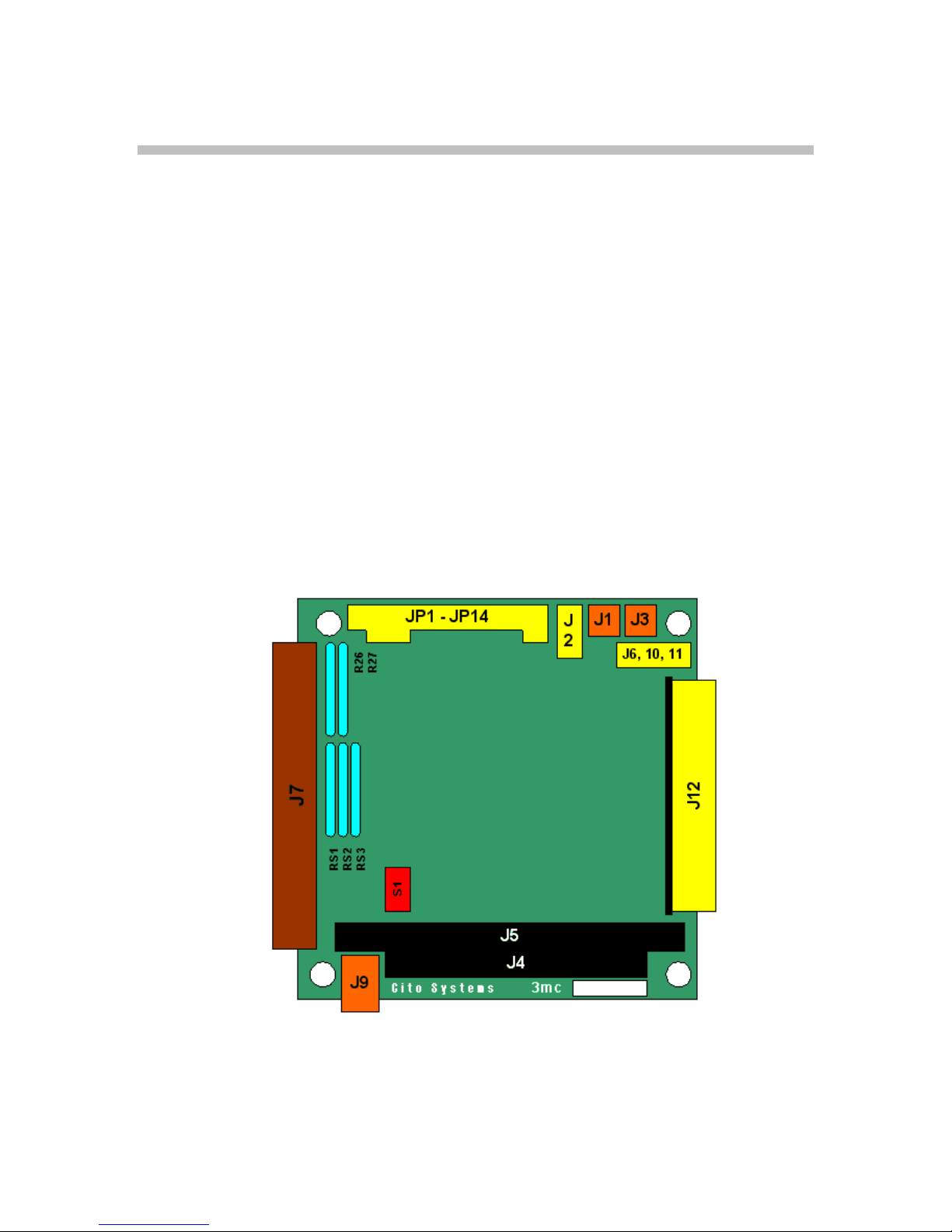
5.1 Appendix A. PC/104 Motion Controller Electrical Reference
5.1.1. PC/104 Motion Card Layout
Figure 5.1 shows the locations of the principal components of the Millennium controller
board. The component side of the board is shown, with the PC/104 bus connector at the
bottom. All component locations in this manual are referred to this orientation.
Jumpers JP1 – JP4 set analog input reference source
Jumpers JP5 & JP6 leave at the default factory setting
Jumper JP7 sets the Host I/O mode
Jumpers JP8 – JP11 set incremental encoder signal type
Jumpers JP12 & JP13 set committed I/O signals voltage supply source
Jumpers JP14 & JP15 set high power digital output configuration
Switch block S1 sets the card’s base address and the IRQ level
Connectors J1 – J12 are described in the second part of this manual
Resistor packs RS1 – RS3 are set according to the type of encoder used
Resistor packs R26 & R27 are set according to external power supply voltage of opto-
isolated committed I/O signals used
Figure 5-1. PC/104 motion controller connector layout
30
Page 31
5.1.2. PC/104 Motion Card Connectors
This section describes the pinouts for the following cable connectors on the Millennium
motion control card (Figure 5-1):
J1 2-pin chipset synchronization signal
J2 5-pin serial asynchronous communication port connector
J3 2-pin host interrupt signal
J6 internal use
J7 100-pin main connector containing encoder input, Hall input, Fault Input, Axis Out
signals, Motor output signals, and limit switch inputs
J8 internal use
J9 4-pin +5V, -12V and +12V power supply
J10 internal use
J11 internal use
J12 44-pin miscellaneous I/O signals connector
5.1.2.1. Motion Processor Synchronization Signal Connector (J1)
Location: Along the upper edge, at the far right corner of the board, between J1 and J3.
This is a 2-pin header (0.1” spacing)
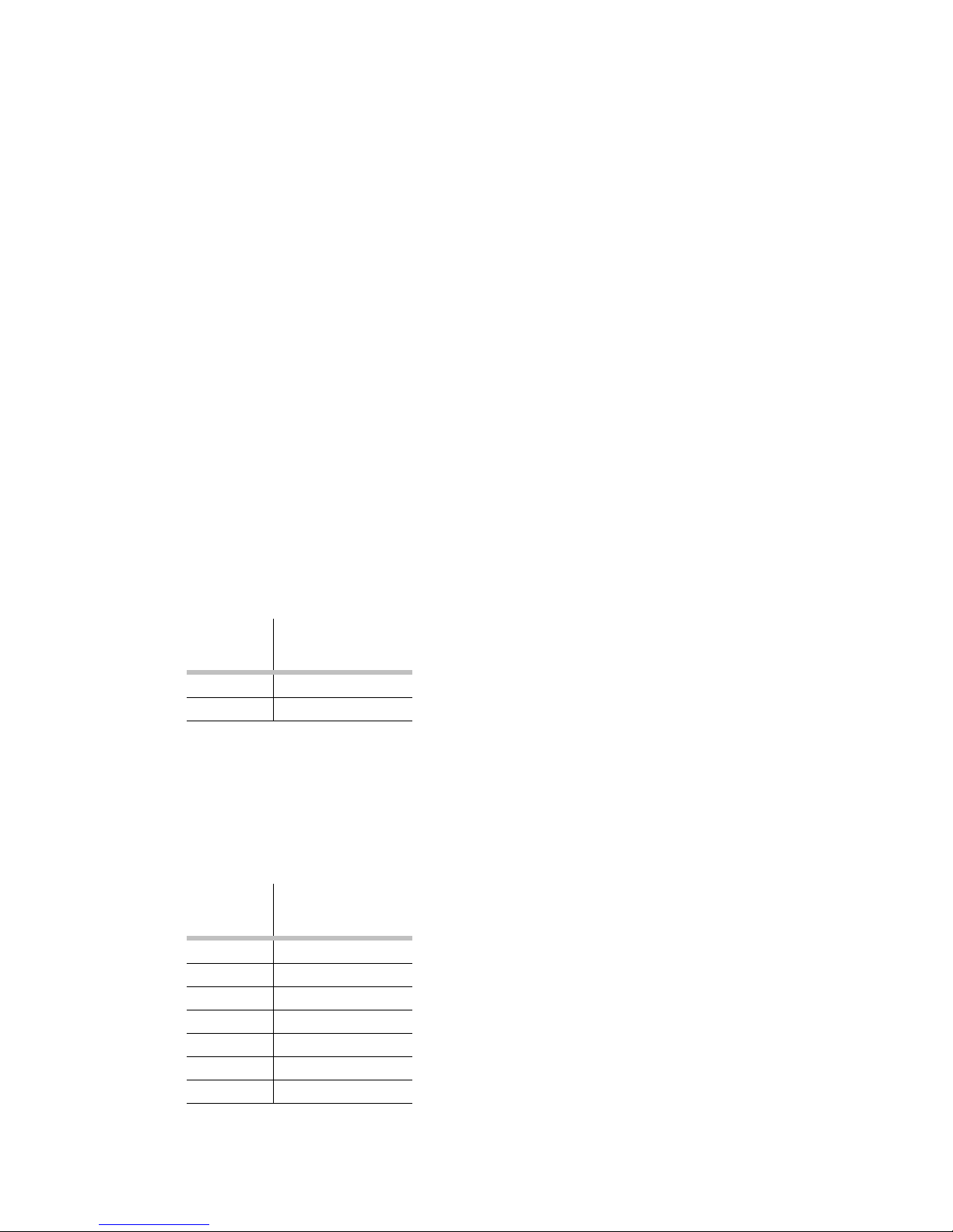
Pin
Signal Name
number
1 Synch
2 GND
This connector provides signal for synchronizing motion processors on different boards.
5.1.2.2. Serial Communication Channel Connector (J2)
Location: Along the upper edge, at the far right corner of the board, next to the J1.
This is a 7-pin single row header (0.1” spacing).
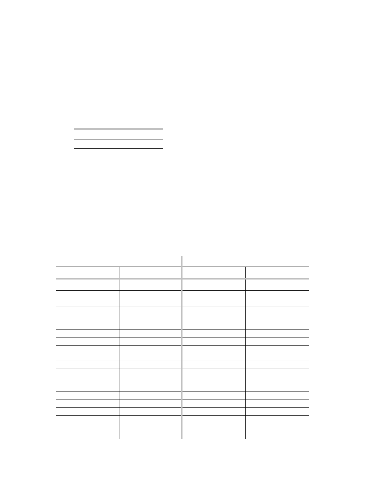
Pin
Signal Name
number
1 SrlXmt
2 SrlRcv
3 Synch
4 RDSSN
5 V
cc
6 GND
7 N/C
31
Page 32
Interface connector for serial link communication adapters.
5.1.2.3. Host Interrupt Signal Connector (J3)
Location: Along the upper edge, at the far right corner of the board, next to J1.
This is a 2-pin header (0.1” spacing)
Pin
Signal Name
number
1 Host interrupt
2 GND
This connector provides the interrupt signal to the outside world.
5.1.2.4. Motion Peripherals Connector (J7)
Location: On the left edge of the board.
This is a 100-pin high-density connector (2x50, 0.05” spacing). The cable assembly that can
be purchased from Cito Systems, consists of two 36” flat ribbon cables terminating together
at one end in the matching 100-pin connector. At the other end, each ribbon terminates in a
50-pin header (2x25, 0.1” spacing). The ribbons are labeled Hdr1 and Hdr2. Pins 1-50 on
Hdr1 connect to pins 1-50 of J7. Pins 1-50 of Hdr2 connect to pins 51-100 of J7.
Header 1
First row
Pin Signal Name Pin Signal Name Pin Signal Name Pin Signal Name
1 QuadA1+ 26 QuadA2+ 1 QuadA3+ 26 QuadA4+
2 QuadA1- 27 QuadA2- 2 QuadA3- 27 QuadA43 QuadB1+ 28 QuadB2+ 3 QuadB3+ 28 QuadB4+
4 QuadB1- 29 QuadB2- 4 QuadB3- 29 QuadB45 Index1+ 30 Index2+ 5 Index3+ 30 Index4+
6 Index1- 31 Index2- 6 Index3- 31 Index47 Vcc (encoder) 32 Vcc (encoder) 7 Vcc (encoder) 32 Vcc (encoder)
8 GND
9 Hall1A 34 Hall2A 9 Hall3A 34 Hall4A
10 Hall1B 35 Hall2B 10 Hall3B 35 Hall4B
11 Hall1C 36 Hall2C 11 Hall3C 36 Hall4C
12 GND (Hall) 37 GND (Hall) 12 GND (Hall) 37 GND (Hall)
13 PosLim1 38 PosLim2 13 PosLim3 38 PosLim4
14 NegLim1 39 NegLim2 14 NegLim3 39 NegLim4
15 Home1 40 Home2 15 Home3 40 Home4
16 Fault1 41 Fault 2 16 Fault 3 41 Fault 4
17 AxisOut1 42 AxisOut2 17 AxisOut3 42 AxisOut4
18 PWMMagA1 43 PWMMagA2 18 PWMMagA3 43 PWMMagA4
to J7 pins 1-50) ( )
(encoder)
Second row Third row Fourth row
33 GND
(encoder)
Header 2
8 GND
(to J7 pins 51-100
(encoder)
33 GND
(encoder)
32
Page 33
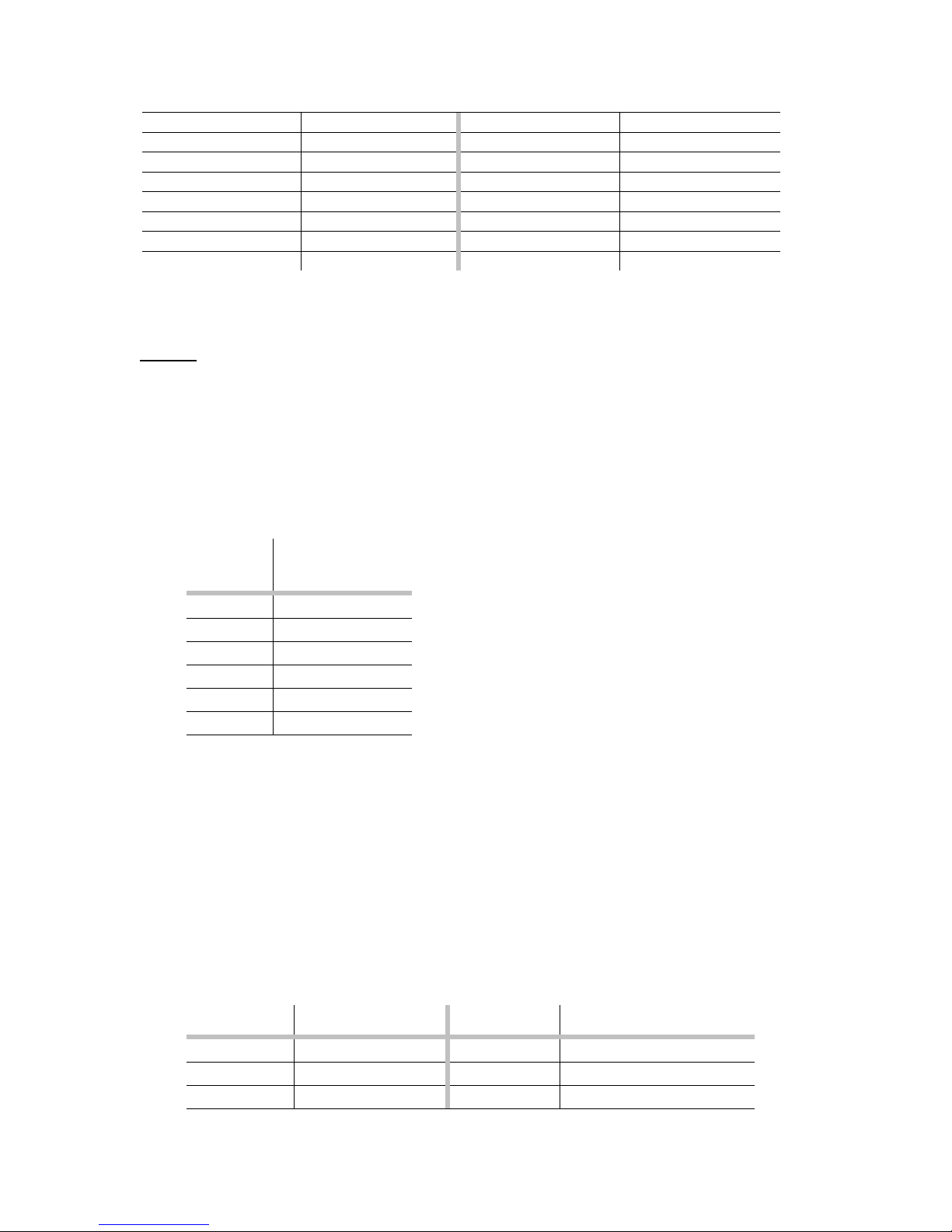
19 PWMMagB1 44 PWMMagB2 19 PWMMagB3 44 PWMMagB4
20 PWMMagC1 45 PWMMagC2 20 PWMMagC3 45 PWMMagC4
21 PWMsign1 46 PWMsign2 21 PWMsign3 46 PWMsign4
22 DACV1* 47 DACV2* 22 DACV3* 47 DACV4*
23 /DACV1* 48 /DACV2* 23 /DACV3* 48 /DACV4*
24 GND (DAC) 49 GND (DAC) 24 GND (DAC) 49 GND (DAC)
25 Opto VSS
50 Opto GND
25 Opto VSS 50 Opto GND
*DACVn and /DACVn, are mapped to two analog output signals for axis n. For non-phased
chipset products (for example MC2401) this is an analog differential control output.
Note 1.
For MC2500 chipset series (stepper motor controllers) signals PWMMagA are used as Pulse
and PWMMagC are used as Direction. The remaining motor signals are not connected.
5.1.2.5. External Power Supply Connector (J9)
Location: Along the lower edge, at the far left corner of the board.
This is a 6-pin single row right-angle header (0.1” spacing).
Pin
Signal Name
number
1 +VS
2 Power GND
3 +5 V
4 GND
5 -12V
6 +12V
This connector harnesses external power supply source signals in case, when the power is
not available through PC/104 bus.
+VS is a supply voltage that can range from +5 to +50 VDC and allowing do derive max.
500 mA current from a single high power digital output.
5.1.2.6. Miscellaneous I/O Signal Connector (J12)
Location: On the right edge of the board.
This is a 44-pin right angle header (2x22, 0.1” spacing).
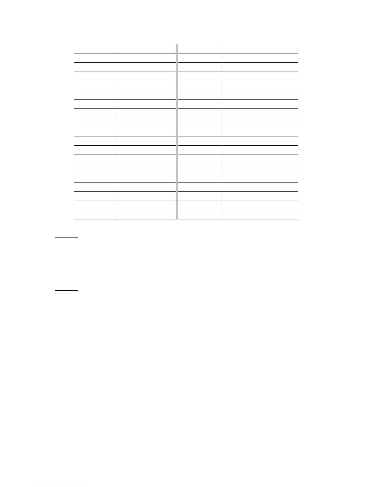
Pin number Signal Name Pin number Signal Name
1 PrlIn 0 23 PrlPwrOut 6
2 PrlIn 1 24 PrlPwrOut 7
3 PrlIn 2 25 Analog Input 1
33
Page 34
4 PrlIn 3 26 Analog Input 2
5 PrlIn 4 27 Analog Input 3
6 PrlIn 5 28 Analog Input 4
7 PrlIn 6 29 Analog Input 5
8 PrlIn 7 30 Analog Input 6
9 PrlOut 0 31 Analog Input 7
10 PrlOut 1 32 Analog Input 8
11 PrlOut 2 33 AnalogRefHigh
12 PrlOut 3 34 AnalogRefLow
13 PrlOut 4 35 AnalogVcc
14 PrlOut 5 36 AnalogGND
15 PrlOut 6 37 Amp Enable 1
16 PrlOut 7 38 Amp Enable 2
17 PrlPwrOut 0 39 Amp Enable 3
18 PrlPwrOut 1 40 Amp Enable 4
19 PrlPwrOut 2 41 Amp Enable +V
20 PrlPwrOut 3 42 Amp Enable GND
21 PrlPwrOut 4 43 External Reset
22 PrlPwrOut 5 44 HSTRDY (internal use)
Note 2.
PrlPwrOut n output signals overlap digital output TTL-level signals PrlOut n. They can be
used to control relays, solenoids, lamps, LED, etc. They can deliver up to 300 mA
continuous current when all of the outputs are ON at +24V. Otherwise, up to max 500 mA
at +50V, depending on the switching cycle.
Note 3.
PrlOut n output signals are overlapped by high power output signals PrlPwrOut. They can
be used when high power logic signals are not desirable to be used e.g. interfacing to CMOS
or TTL logic.
5.1.3. PC/104 Motion Controller Configuration Jumpers and Switch Block
Settings
The PC/104 motion control board employs a set of jumpers and a block of microswitches
for some hardware configuration. The jumper bank is located along the upper edge of the
board, while the switch block in its lower part, close to the bus connectors J4 and J5. This
section describes settings of the jumpers and the switch block for possible hardware
configurations.
5.1.3.1. Setting the Host I/O Mode – JP7
The PC/104 motion controller supports two different communication modes.
34
Page 35
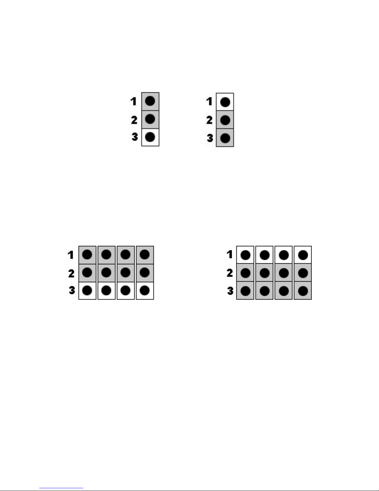
The figure below shows how the JP7 jumper should be installed to select the host mode.
PC/104 mode is the default. Shading indicates the location of the jumper.
JP7 JP7
serial port PC/104 parallel
The default Host I/O mode setting is “PC/104 bus"
5.1.3.2. Setting the Incremental Encoders Input Signal – JP8 - JP11
The Millennium series controllers support differential or single-end incremental encoder
outputs. The figure below shows how JP8 – JP11 jumpers should be installed to select the
encoder output signal.
JP11 JP10 JP8 JP9 JP11 JP10 JP8 JP9
Differential Single-ended
The default incremental encoder output signal setting is "Differential"
5.1.3.3. Setting the Committed I/O Signal Voltage Supply Source – JP12 &
JP13
The PC/104 motion controllers use opto-isolation on the HOME, LIM“-“, LIM”+” and
FAULT dedicated input signals. For applications that do not demand opto-isolation the
internal +5VDC supply voltage can be used, otherwise an external power supply voltage has
to be applied. If the board internal supply voltage is used, the jumpers JP12 & JP13 should
be installed, otherwise they must be removed.
The default committed I/O signal voltage supply source setting is "Internal"
35
Page 36
5.1.3.4. Setting the High Power Digital Output – JP14 & JP15
The PC/104 motion board provides high voltage high current digital signals on the J12
connector. These output signals can work either as current sink with ULN2803 or current
source with UDN2982. It is up to customer order, what type of output driver should be
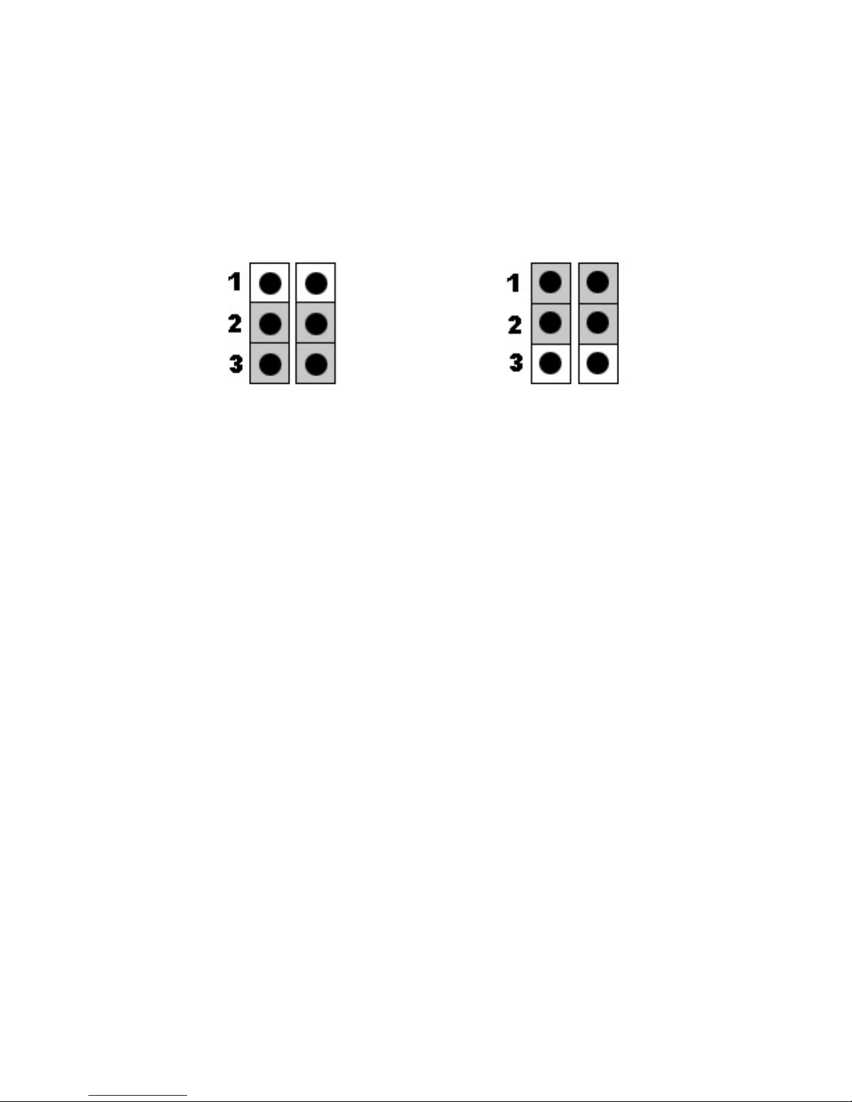
installed. The figure below shows how JP14 & JP15 jumpers should be installed to select the
digital output configuration.
JP15 JP14 JP15 JP14
Current source Current sink
UDN2982 ULN2803
The default high power digital output signal setting is "current source"
5.1.3.5. Setting the Analog Input Voltage Reference Source – JP1 – JP4
The PC/104 motion controller supports analog input signals on the J12 connector. The
reference voltage is provided internally as +5 VDC or can be supplied from an external
source. If the board internal reference source is used, the jumpers JP1, JP2, JP3 & JP4
should be installed, otherwise they must be removed.
The default analog input voltage reference source setting is "Internal"
Note:
Jumpers JP5 & JP6 should follow the factory setting – JP5 installed on 1&2
and JP6 removed.
5.1.3.6. Setting the Base Address and the IRQ Level – S1
DIP switch block S1
Switch block S1 is oriented vertically on the controller board; “ON” is the position to the
right.
S1 switches 1-4: base I/O address
Address S1-1 S1-2 S1-3 S1-4
300h
310h
320h
330h
340h
36
Page 37

350h
360h
370h
380h
390h
3A0h
3B0h
3C0h
3D0h
3E0h
3F0h
S1 switches 5-8: IRQ
IRQ S1-5 S1-6 S1-7 S1-8
3
5
7
10
11
12
14
15
IRQ
disabled
– – –
5.2 Appendix B. Outputs to Motor Amplifiers
The controller board supports three types of output to the motor amplifiers:
DAC Analog signals from the on-board D/A converters
PWM 50/50 Pulse-width modulated square-wave signals with a 50% duty cycle
PWM sign-magnitude Pulse-width modulated signals with definable duty cycle and
direction
These outputs should be connected from the designated J7 pins to the appropriate amplifier
inputs, as shown in the following tables. The names of the inputs pins may vary among
amplifiers; common names are shown.
5.2.1. Brushed Servo Motors (MC2100 series)
DAC DACAn Ref+ or V+ Hdr1-22 Hdr1-47 Hdr2-22 Hdr2-47
/DACAn Ref- or V- Hdr1-23 Hdr1-48 Hdr2-23 Hdr2-48
GNDn Ref- or Gnd Hdr1-24 Hdr1-49 Hdr2-24 Hdr2-49
Signal
name
Amplifier
input
J7 connection (Header-pin]
Axis 1 Axis 2 Axis 3 Axis 4
37
Page 38
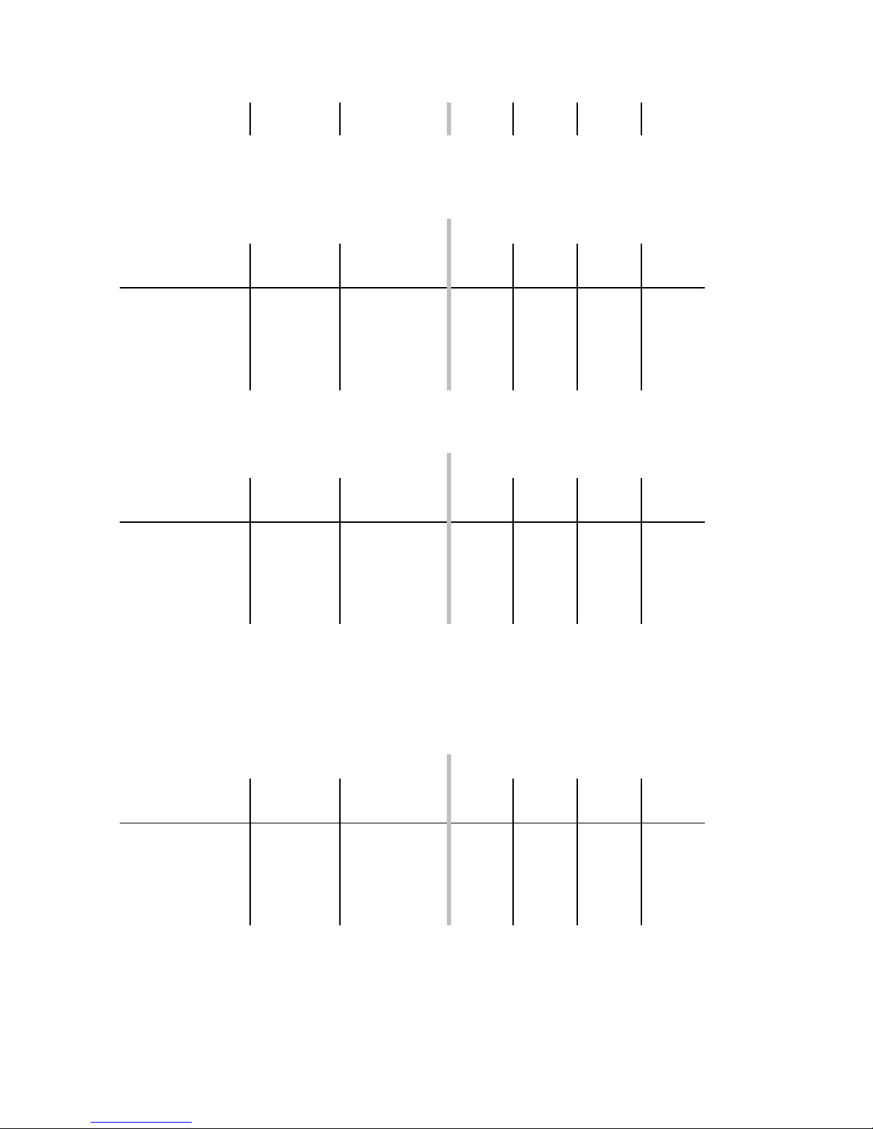
PWM sign-magnitude PWMMagAn PWM magnitude Hdr1-18 Hdr1-43 Hdr2-18 Hdr2-43
PWMSignAn PWM direction Hdr1-21 Hdr1-46 Hdr2-21 Hdr2-46
5.2.2. Brushless Servo Motors (MC2300 series)
J7 connection (Header-pin)
Signal
name
DAC DACAn Ref1+ or V1+ Hdr1-22 Hdr1-47 Hdr2-22 Hdr2-47
DACBn Ref2+ or V2+ Hdr1-23 Hdr1-48 Hdr2-23 Hdr2-48
GNDn Ref- or Gnd Hdr1-24 Hdr1-49 Hdr2-24 Hdr2-49
PWM 50/50 PWMMagAn PWM phase 1 Hdr1-18 Hdr1-43 Hdr2-18 Hdr2-43
PWMMagBn PWM phase 2 Hdr1-19 Hdr1-44 Hdr2-19 Hdr2-44
PWMMagCn PWM phase 3 Hdr1-20 Hdr1-45 Hdr2-20 Hdr2-45
Amplifier
input
Axis 1 Axis 2 Axis 3 Axis 4
5.2.3. Brush and Brushless Servo Motors (MC2800 series)
Signal
name
DAC DACAn Ref1+ or V1+ Hdr1-22 Hdr1-47 Hdr2-22 Hdr2-47
DACB*n Ref2+ or V2+ Hdr1-23 Hdr1-48 Hdr2-23 Hdr2-48
GNDn Ref- or Gnd Hdr1-24 Hdr1-49 Hdr2-24 Hdr2-49
PWM 50/50 PWMMagAn PWM phase 1 Hdr1-18 Hdr1-43 Hdr2-18 Hdr2-43
PWMMagB*n PWM phase 2 Hdr1-19 Hdr1-44 Hdr2-19 Hdr2-44
PWMMagC*n PWM phase 3 Hdr1-20 Hdr1-45 Hdr2-20 Hdr2-45
Amplifier
input
J7 connection (Header-pin)
Axis 1 Axis 2 Axis 3 Axis 4
Note:
* - depends on user axes designation
5.2.4. Microstepping Motors (MC2400 series)
Signal
name
DAC DACAn Ref1+ or V1+ Hdr1-22 Hdr1-47 Hdr2-22 Hdr2-47
DACBn Ref2+ or V2+ Hdr1-23 Hdr1-48 Hdr2-23 Hdr2-48
GNDn Ref- or Gnd Hdr1-24 Hdr1-49 Hdr2-24 Hdr2-49
PWM 50/50 PWMMagAn PWM phase 1 Hdr1-18 Hdr1-43 Hdr2-18 Hdr2-43
PWMMagBn PWM phase 2 Hdr1-19 Hdr1-44 Hdr2-19 Hdr2-44
PWMMagCn PWM phase 3 Hdr1-20 Hdr1-45 Hdr2-20 Hdr2-45
Amplifier
input
J7 connection (Header-pin)
Axis 1 Axis 2 Axis 3 Axis 4
38
Page 39
5.2.5. Stepper Motors (MC2500 series)
Pulse/Direction Pulsen Pulse train Hdr1-18 Hdr1-43 Hdr2-18 Hdr2-43
Directionn Direction signal Hdr1-20 Hdr1-45 Hdr2-20 Hdr2-45
Signal
name
Amplifier
input
J7 connection (Header-pin)
Axis 1 Axis 2 Axis 3 Axis 4
5.3 Appendix C. Encoder Inputs
Resistor packs RS1 – RS3.
The three resistor packs are at the left edge of the controller board, next to the 100-pin
connector J7. When using differential encoders, leave these packs in place. When using
single-ended encoders, remove all three packs. Encoder connections are listed in the
below table.
Axis 1 Axis 2 Axis 3 Axis 4
A
~A
B
~B
Index
~Inde
x
v
cc
GND
Encoder connections on J7
Hdr1-1 Hdr1-26 Hdr1-51 Hdr1-76
Hdr1-2 Hdr1-27 Hdr1-52 Hdr1-77
Hdr1-3 Hdr1-28 Hdr1-53 Hdr1-78
Hdr1-4 Hdr1-29 Hdr1-54 Hdr1-79
Hdr1-5 Hdr1-30 Hdr1-55 Hdr1-80
Hdr1-6 Hdr1-31 Hdr1-56 Hdr1-81
Hdr1-7 Hdr1-32 Hdr1-57 Hdr1-82
Hdr1-8 Hdr1-33 Hdr1-58 Hdr1-83
5.4 Appendix D. Opto-isolated Committed Inputs
Resistor packs R26 & R27.
The three resistor packs are at the left end of the controller board, next to the 100-pin
connector J7. When using opto-isolation of committed input signals – the fault, home and
limit switches powered by an external power supply appropriate values need to be installed.
The table below shows the resistor packs values corresponding to different external power
supply voltage levels applied.
External supply
voltage (+VS)
5V
Resistor
value
330 Ω
39
Page 40
12-15V
24V
48V
1.2kΩ
2.2 kΩ
4.7kΩ
The default factory setting is 2.2kOhm for +24V external supply voltage.
5.5 Appendix E. PC/104 Motion Controller Signal Connections
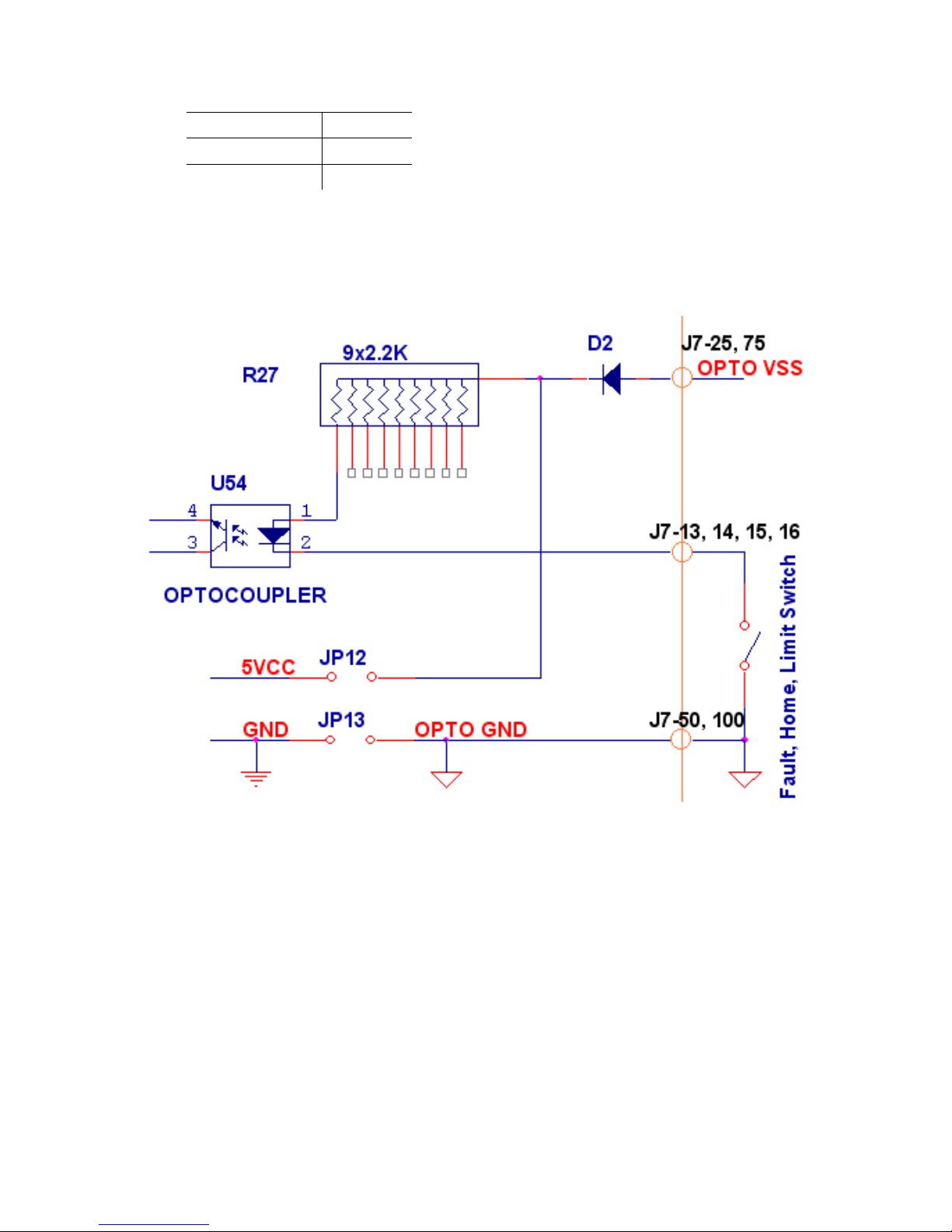
Fig. 5-2. Connecting dedicated inputs of limit and home switches to the controller.
40
Page 41
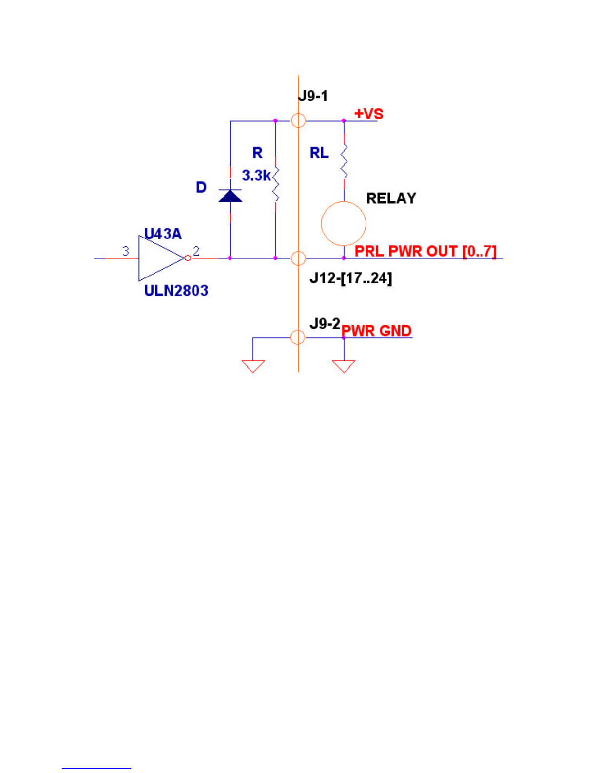
Fig 5-3. Connecting outputs in a version of ULN2803 through ULN2824 high
current sinking driver – J12 connector.
41
Page 42
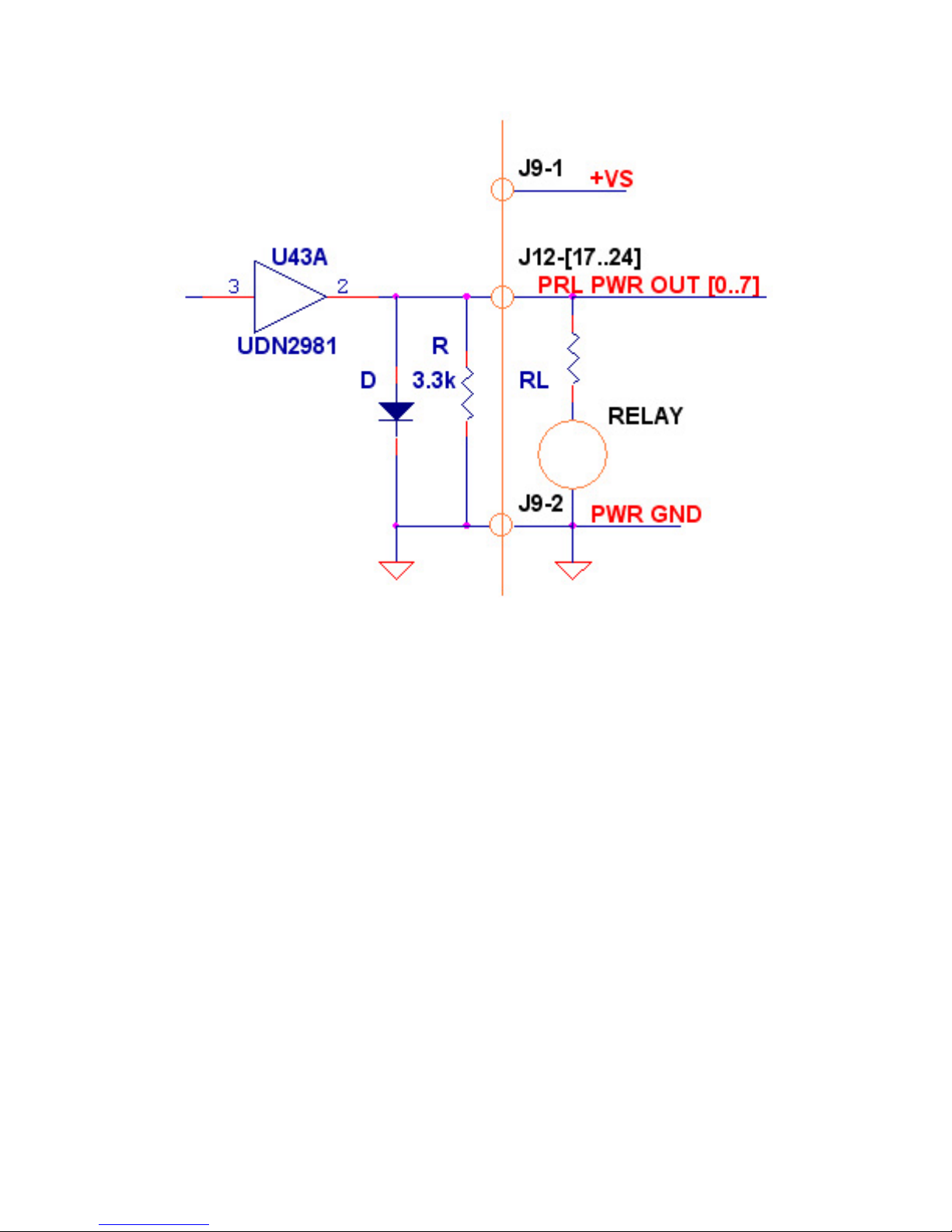
Fig 5-4. Connecting outputs in a version of UDN2981 through UDN2984 high
current sourcing driver – J12 connector.
5.6 Appendix F. PC/104 Motion Controller Hardware Information
Environmental and Electrical Ratings
Dimensions
Storage Temperature
Operating Temperature
Power Consumption
Supply Voltage limits
Supply Voltage operating
range
High power digital output
supply voltage range
Max. current derived from
high power digital I/O
Analog Output range
Analog Input range
3.945” x 3.775” (100.2 mm x 95.9 mm),
PC/104 Adapter
-40 °C to 125 °C
0 °C to 70 °C*
1A @ 5V; 83mA @ 12V
-0.3V to +7.0V
4.75V to 5.25V
5.0V to 50.0V
500 mA with variable cycle, 300 mA constant
-10.0V to 10.0V
0.0V to 5.0V
42
 Loading...