

Page 1
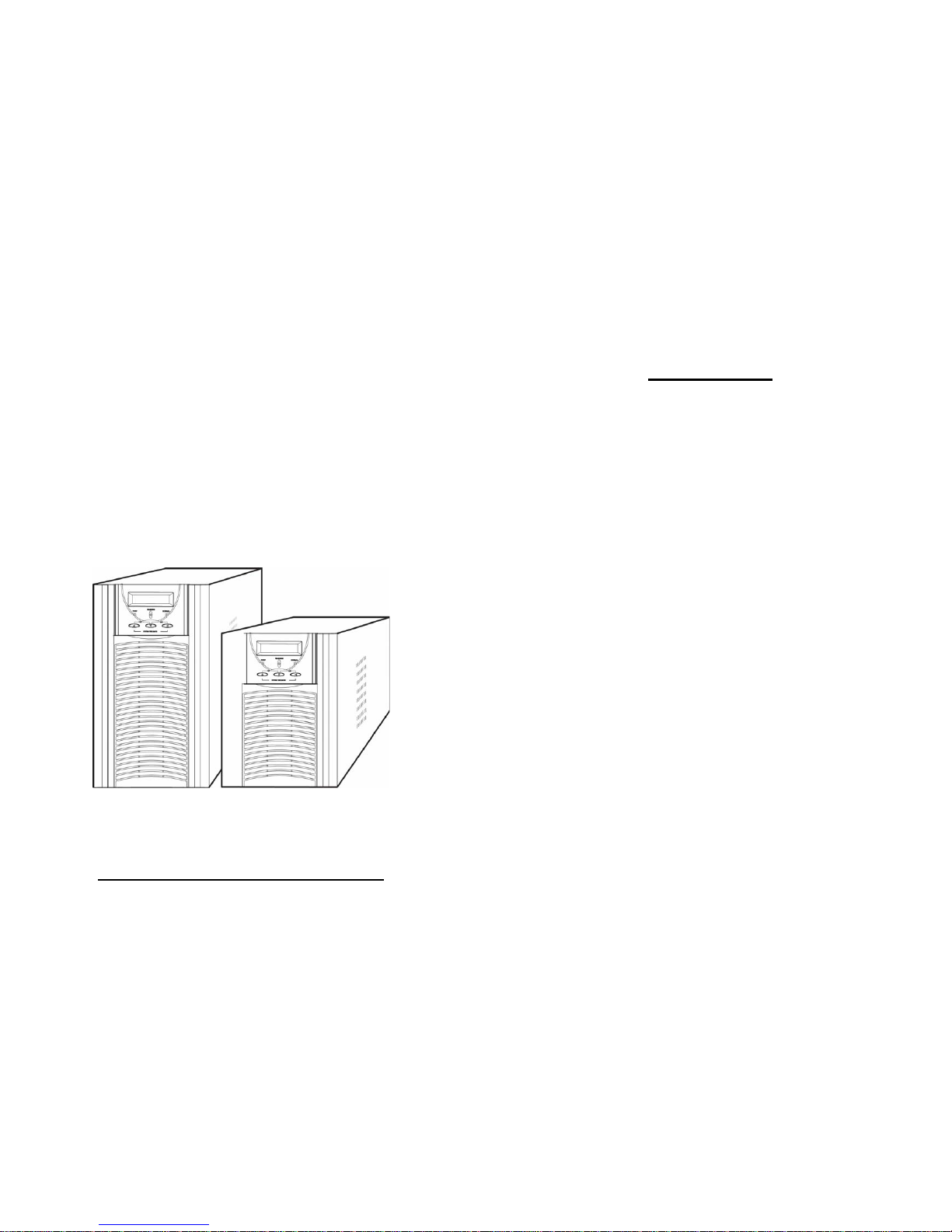
USER’S MANUAL
CiTO Power - ON-SAFE Series
CPO-S1000 / CPO-S2000 / CPO-S3000 /
CPO-S1000R / CPO-S2000R / CPO-S3000R
Uninterruptible Power Supply
1
CONTENTS
1. INTRODUCTION .............................................……........ 1
2. SAFTY INSTRUCTION...................……...…………….... 2
3. SYSTEM DESCRIPTION..........................……......…..... 4
4. CABLE CONNECTION ..............................…….......…... 7
5. OPERATION ................................................……........... 8
6. TROUBLE SHOOTING GUIDE.......................…….....… 13
7. OPERATION MODES OF THE UPS ..............……........ 17
8. COMPUTER INTERFACE ...........................……........... 19
9. SPECIFICATIONS.................................…………..…..... 21
Page 2

2
1. INTRODUCTION
1.1 General Description
The continuity of electrical power is an essential requirement for critical load
operations .The Uninterruptible Power System (UPS) is designed to meet the
user‘s need of present computer, server and the equipment of office
automation that make the UPS more compact and less noisy.
To choose the UPS as your equipment protector is a wise investment
because it supplies reliable, pure and stable power at affordable price.
1.2 Key features
1. Multiple microprocessor and double-conversion design base.
2. Wide input range designed to operate under harsh environment.
3. High input power factor and DC-start function.
4. LED and LCD display for detail status and data; real-time alarm silence.
5. Enhanced protections against light, surges, and disturbance etc.
6. Remote monitoring with SNMP intelligent slot and RS-232 interface.
7. Light weight and compact size, easy to transport and place.
1.3 Important Notices
To be sure that the UPS will be operated correctly, the following items should
be noticed:
1. Read instructions carefully before operating the UPS.
2. UPS power connect instruction should be followed.
3. Please don‘t open the case to prevent danger.
4. If the UPS will be stored for long period, the battery must be charged once
every 90 days.
5. Retain the load within the rating of UPS to prevent faults.
6. Handle unusual events according to the trouble-shooting guide.
7. Keep the UPS clean and dry.
3
2. SAFTY INSTRUCTION
2.1 Transporting
1. Disconnect all power cables if necessary.
2. Be careful not to damage the UPS while transporting.
3. Don‘t move the UPS upside down.
4. Please transport the UPS system only in the original packaging (to protect
against shock and impact).
2.2 Positioning
1.Do not put the UPS on rugged or declined surface.
2.Do not install the UPS system near water or in damp environments.
3.Do not install the UPS system where it would be exposed to direct sunlight
or near heat.
4.Do not block off ventilation openings in the UPS system’s housing and don’t
leave objects on the top of the UPS.
5.Allow a minimum distance of 10 cm in the rear and two sides of the UPS for
ventilation.
6.Keep the UPS far away from heat emitting sources.
7.Do not expose it to corrosive gas.
8.Ambient temperature : 0℃ - 40℃
2.3 Installation
1. Connect the UPS system only to an earthed shockproof socket outlet.
2. Do not connect domestic appliances such as hair dryers or office equipment
which would overload the UPS system (e.g. laser printers) to UPS output
sockets.
3. Place cables in such a way that no one can step on or trip over them.
Page 3
4
2.4 Operation
1. Do not disconnect the mains cable on the UPS system or the building wiring
socket outlet during operations since this would cancel the protective
earthing of the UPS system and of all connected loads.
2. The UPS has its own internal power source (batteries). The output terminals
may be live even when the UPS is not connected to the AC supply.
3. Ensure that no fluids or other foreign objects can enter the UPS system.
2.5 Maintenance and Service
1. Caution - risk of electric shock.
Even after the unit is disconnected from the mains power supply (building
wiring socket outlet), components inside the UPS system are still connected
to the battery and are still electrically live and dangerous. Before carrying
out any kind of servicing and/or maintenance, disconnect the batteries and
verify that no current is present.
2. Only persons adequately familiar with batteries and with the required
precautionary measures may exchange batteries and supervise operations.
Unauthorised persons must be kept well away from the batteries.
3. Batteries may cause electric shock and have a high short-circuit current.
Please take the precautionary measures specified below and any other
measures necessary when working with batteries:
- remove wristwatches, rings and other metal objects
- use only tools with insulated grips and handles.
4. When changing batteries, install the same number and same type of
batteries.
5. Do not attempt to dispose of batteries by burning them. This could cause
battery explosion.
6. Do not open or destroy batteries. Escaping electrolyte can cause injury to
the skin and eyes.
5
3. SYSTEM DESCRIPTION
3.1 Front Panel
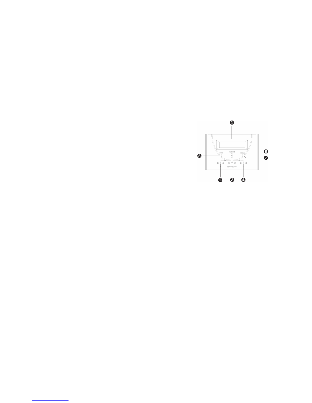
1. LCD Display: This indicates the UPS operation information, including UPS
status, input/output voltage, input/output frequency, battery voltage,
battery capacity left, output load, inside temperature, and the times of
history events.
2. LCD Select Up-key: It is pressed to select upward the UPS status on LCD
Display.
3. LCD Select Down-key: It is pressed to select downward the UPS status on
LCD Display.
4. Control Key: When this key is pressed with the LCD Select Down-key
simultaneously for 3 seconds, the UPS will be switched on after two beeps.
Similarly, when UPS is in operation press this key and the LCD Select
Up-key for 3 seconds, the UPS will be switched off after two beeps.
Beside, in battery operation mode, press both of this key and LCD Select
Up-key at the same time to disable the buzzer.
Page 4
6
5. Fault LED (red): To indicate the UPS is in fault condition because of
inverter shutdown or over-temperature.
6. Warning LED (yellow): To indicate the UPS is in the status of overload,
bypass and battery back-up.
7. Normal LED (green): To indicate the UPS is operating normally.
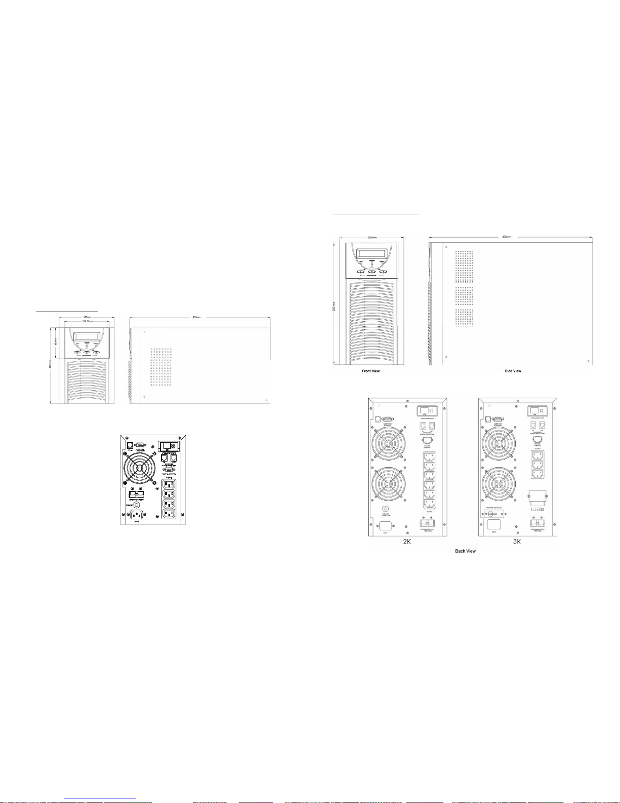
3.2 Outline Description
1KVA Tower Case
FRONT VIEW SIDE VIEW
BACK VIEW
7
2KVA / 3KVA Tower Case
Page 5
8
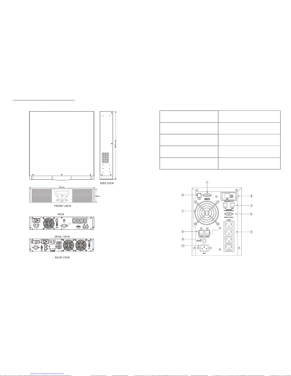
1KVA / 2KVA / 3KVA Rack Mount Case
9
3.3 Back View Description
1. DB 9 (RS-232) Interface Port
6. Remote Control
(Mini LCD for LED panel only, Option)
2. SNMP Intelligent Slot (Option) 7. Fan
3. Fax / Modem (Surge Protection) 8. External Battery Socket
4. Remote Control
(Detachable LCD Panel, Option)
9. Breaker
5. Output Socket (NEMA or IEC) 10. Input Socket
Page 6
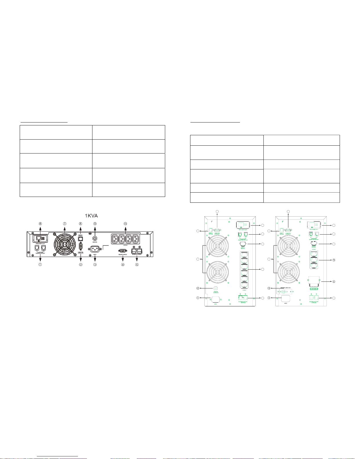
10
1KVA Rack Mount Case
1. Fax / Modem (Surge Protection) 6. SNMP Intelligent Slot (Option)
2. DB 9 (RS-232) Interface Port 7. Fan
3. Input Socket
8. Remote Control
(Small LCD Panel, Option)
4. Remote Control
(Detachable LCD Panel, Option)
9. Breaker
5. External Battery Socket 10. Output Socket (NEMA or IEC)
11
2KVA / 3KVA Tower Case
1. DB 9 (RS-232) Interface Port 7. External Battery Socket
2. SNMP Intelligent Slot (Option)
8. Remote Control
(Mini LCD for LED panel only, Option)
3. Fax / Modem (Surge Protection) 9. Fan
4. Remote Control
(Detachable LCD Panel, Option)
10. Breaker
5. Output Socket (NEMA or IEC) 11. Input Terminal
6. Output Terminal
BACK VIEW
2KVA 3KVA
1
2
3
4
5
7
9
8
1
2
3
4
7
9
8
Page 7
12
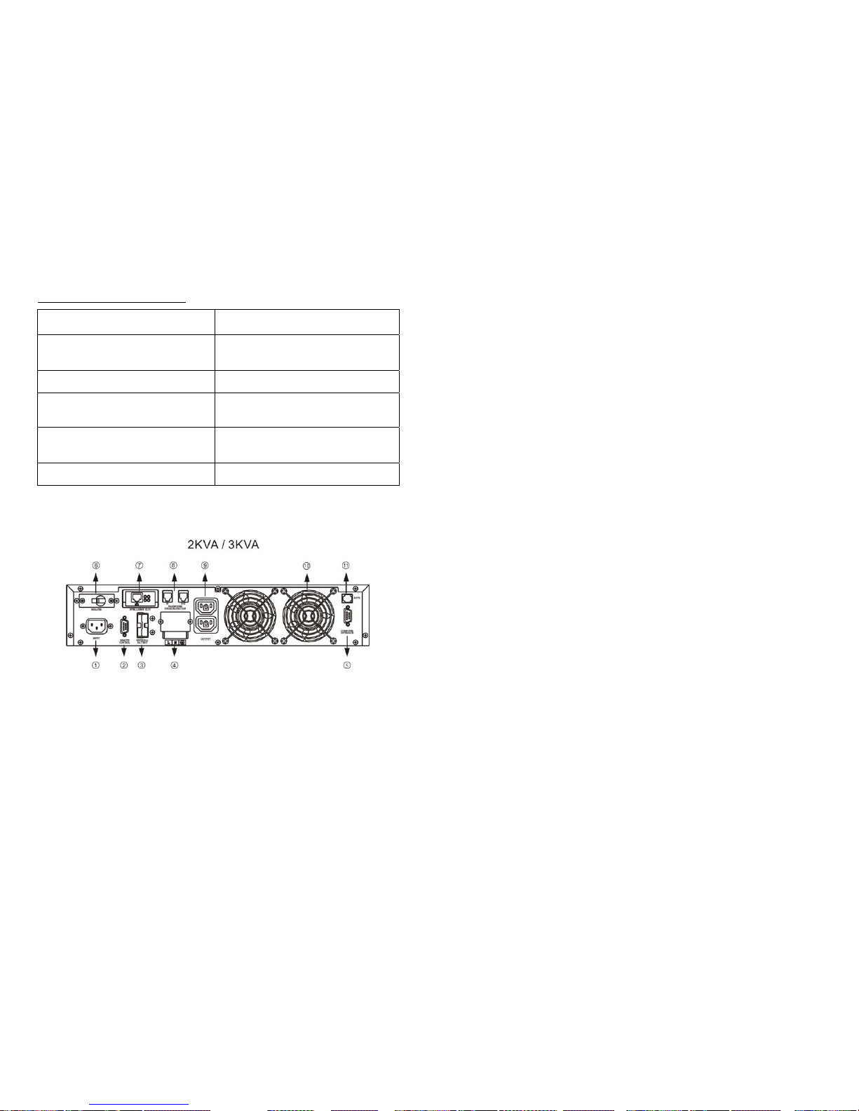
2KVA / 3KVA Rack Mount Case
1. Input Socket 7. SNMP Intelligent Slot (Option)
2. Remote Control
(Detachable LCD Panel, Option)
8. Fax / Modem (Surge Protection)
3. External Battery Socket 9. Output Socket (NEMA or IEC)
4. Output Terminal 10. Fan
5. DB 9 (RS-232) Interface Port
11. Remote Control
(Small LCD Panel, Option)
6. Breaker
13
4.
CABLE CONNECTION
4.1 Inspection
1. The system may be installed and wired only by qualified electricians in
accordance with applicable safety regulations.
2. When installing the electrical wiring, please note the nominal amperage of
your incoming feeder.
3. Inspect the packaging carton and its contents for damage. Please inform
the transport agency immediately should you find signs of damage.
Please keep the packaging in a safe place for future use.
4. Please ensure that the incoming feeder is isolated and secured to prevent
it from being switched back on again.
4.2 Connection
1. UPS Input Connection
If the UPS is connected via the power cord, please use a proper socket
with protection against electric current, and pay attention to the capacity of
the socket.
2. UPS Output Connection
The output of this model is with socket-types only (NEMA or IEC). Simply
plug the load power cord to the output sockets to complete connection.
Page 8
14
5. OPERATION
5.1 Check Prior to Start Up
1. Ensure the UPS is in a suitable positioning.
2. Check input cord is secured.
3. Make sure the load is disconnected or in the “OFF” position.
4. Check if input voltage meets the UPS rating required.
5.2 Operation Procedure
Please follow the instructions below for the UPS operation.
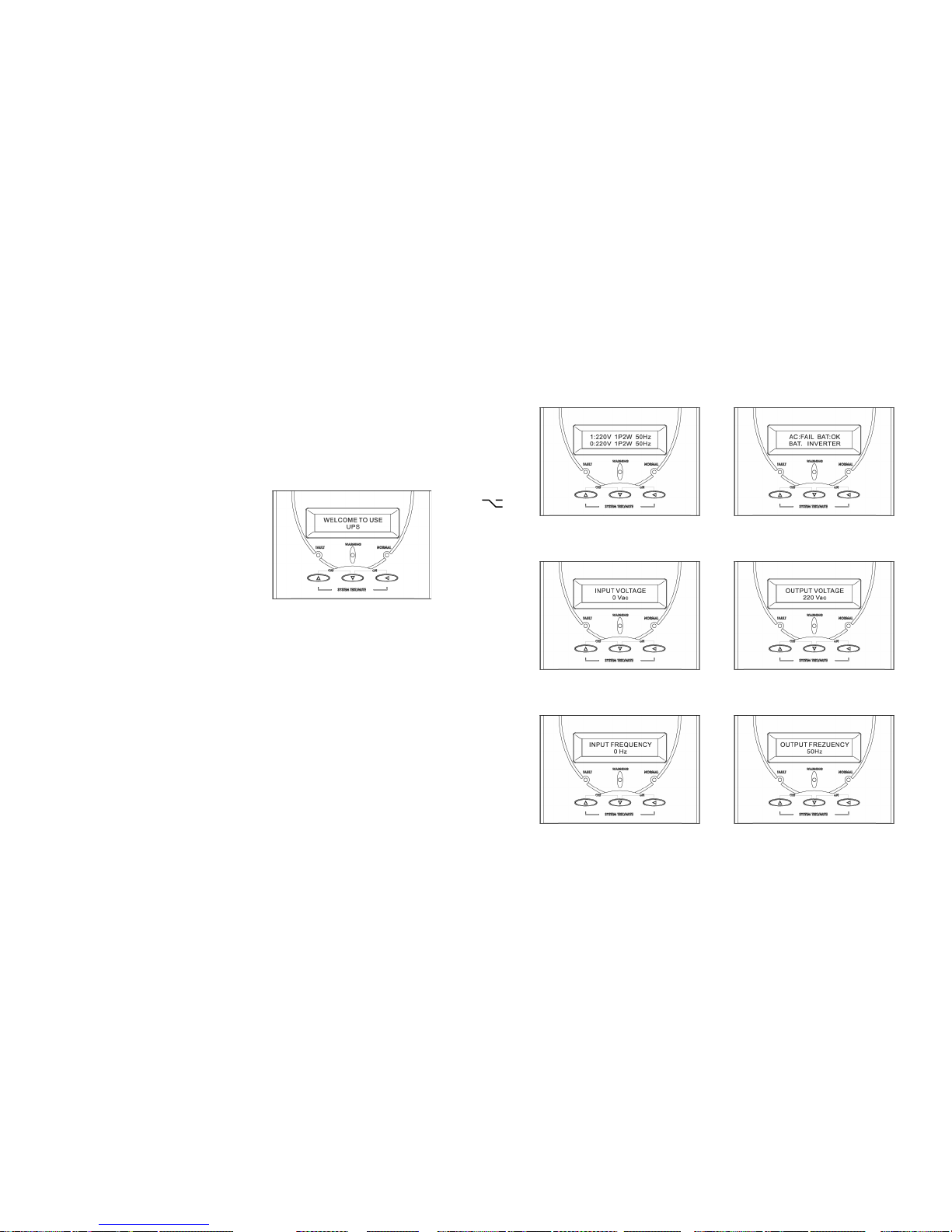
1. Once the AC source is connected, the
LCD Display shall light up immediately
to display first the main menu of
greeting context and the Normal LED is
blinking to indicate ready to switch on
the inverter.
2. By pressing the UPS on/off Control Key and the LCD Select Down-key
simultaneously for 3 seconds until the buzzer beeps twice, the UPS will
start up and Normal LED lights up to indicate the power is from its inverter
to the load.
3. When the UPS on/off Control Key and the LCD Select Up-key are pressed
simultaneously for 3 seconds until the buzzer beeps twice, the inverter will
be turned off and the UPS is on the standby status (LCD display illuminates
and Normal LED is blinking) until AC source is disconnected.
5.3 Storage Instruction
Disconnect input power in rear panel if you will not use it for long period. If the
UPS is stored over 3 months, please keep supplying power to the UPS for at
least 24 hours to ensure battery fully recharged.
15
5.4 LCD Display
Use Up/Down key to select menu-displays of the LCD described below. This
screen will refresh once the system power is enabled.
1. Rated Spec Menu
2. Status Menu
3. Voltage Menu
4. Frequency Menu
Page 9
16
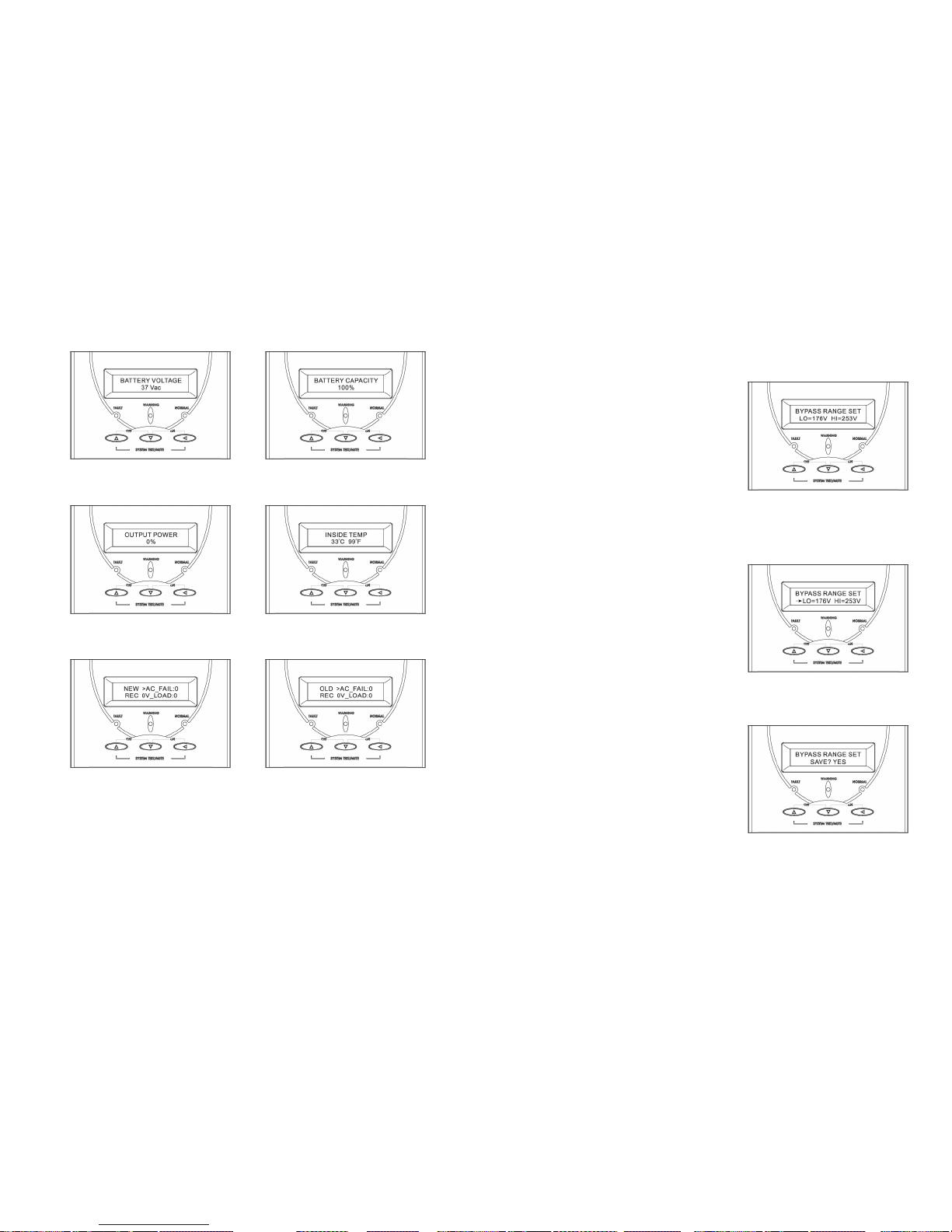
5. Battery Status Menu
6. Output Power Menu
7. Temperature Menu
8. History Record Menu
17
9. Bypass Range Set Menu
A. To protect the load, the function
of bypass auto-transfer is
activated only when the AC main
voltage is within the range of LO
(low) and HI(high). In this screen,
press on/off Control Key to enter
the following steps for LO/HI
voltage setting.
B. The cursor (→) will pop up to
indicate the item newly selected.
Press on/off Control Key to get
the item of LO or HI range the
user want to adjust.
C. Use Up or Down-key to adjust
the voltage (changing 1V by
every press). LO (low
rang):176V+/- 20V, HI(high
range):253V+/- 20V).
D. Once the value is confirmed,
press on/off Control Key again to
save the data.
Page 10
18
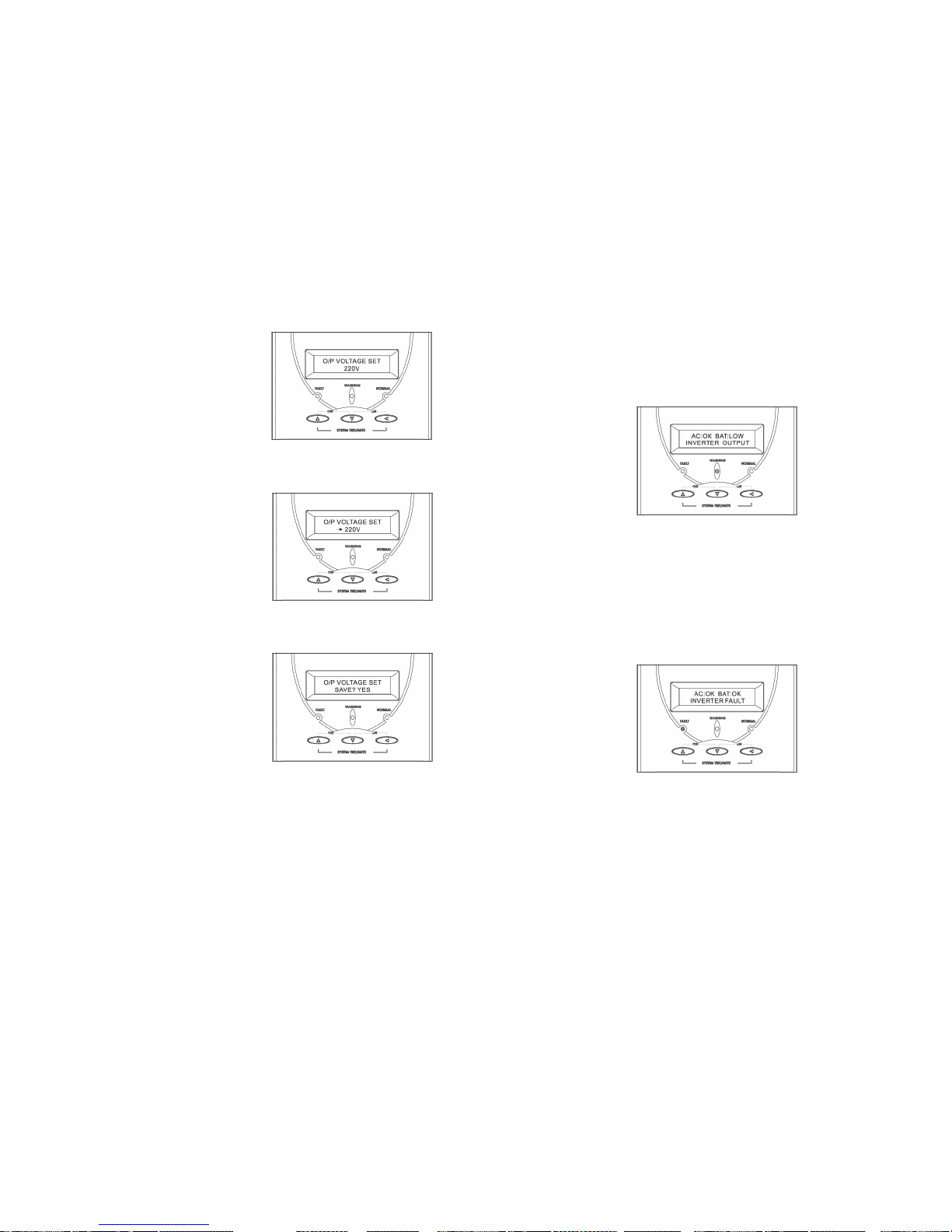
10. Output Voltage Set Menu
A. In this screen, press on/off
Control Key to enter the following
steps for output voltage setting.
B. The cursor (→) will pop up to
indicate the output voltage newly
selected.
C. Use Up or Down-key to adjust
the output voltage (220V, 230V,
and 240V are available only).
D. Once the correct voltage is
selected, press on/off Control
Key again to save the data.
19
6. TROUBLE SHOOTING GUIDE
6.1 UPS Status and Action
The description of the following guideline may be helpful in problem solving.
1. LED and LCD status as below:
UPS STATUS:
AC utility power is normal. UPS is running normally, but battery
capacity is low (referring to Battery Status Menu). Buzzer beeps once
every second for battery low.
ACTION: Charger may be defective. Please replace charger board.
2. LED and LCD status as below:
UPS STATUS:
AC utility power is normal. The output load is supplied through bypass
of AC utility. Fault LED lits up and buzzer beeps continuously.
ACTION: Please contact your agent for service.
Page 11
20
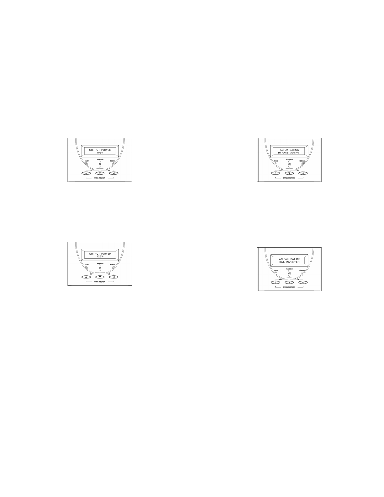
3. LED and LCD status as below:
UPS STATUS:
AC utility power is normal but UPS is overloaded. Warning LED lights
up and buzzer beeps per second.
ACTION: Please reduce the critical load to POWER(%)<100%.
4. LED and LCD status as below:
UPS STATUS:
AC utility power is normal but UPS is overloaded up to 125%. Warning
LED does not fade out and buzzer beeps per 0.5 second.
ACTION: Please reduce the critical load to POWER(%)<100%.
21
5. LED and LCD status as below:
UPS STATUS:
AC utility power is normal, but the load is supplied by AC utility power
via bypass. Output power is more than 150% (referring to the Output
Power Menu). Warning LED lights up and buzzer beeps continuously.
ACTION: Please reduce the critical load to POWER(%)<100%.
6. LED and LCD status as below:
UPS STATUS:
AC utility power fails .The full load is supplied by battery power in UPS.
Buzzer alarm sounds every 4 seconds.
ACTION: If AC utility power fails, reduce the critical load in order to
extend backup time. If it is not abnormal power failure, please check
the rated input or connected line.
Page 12
22
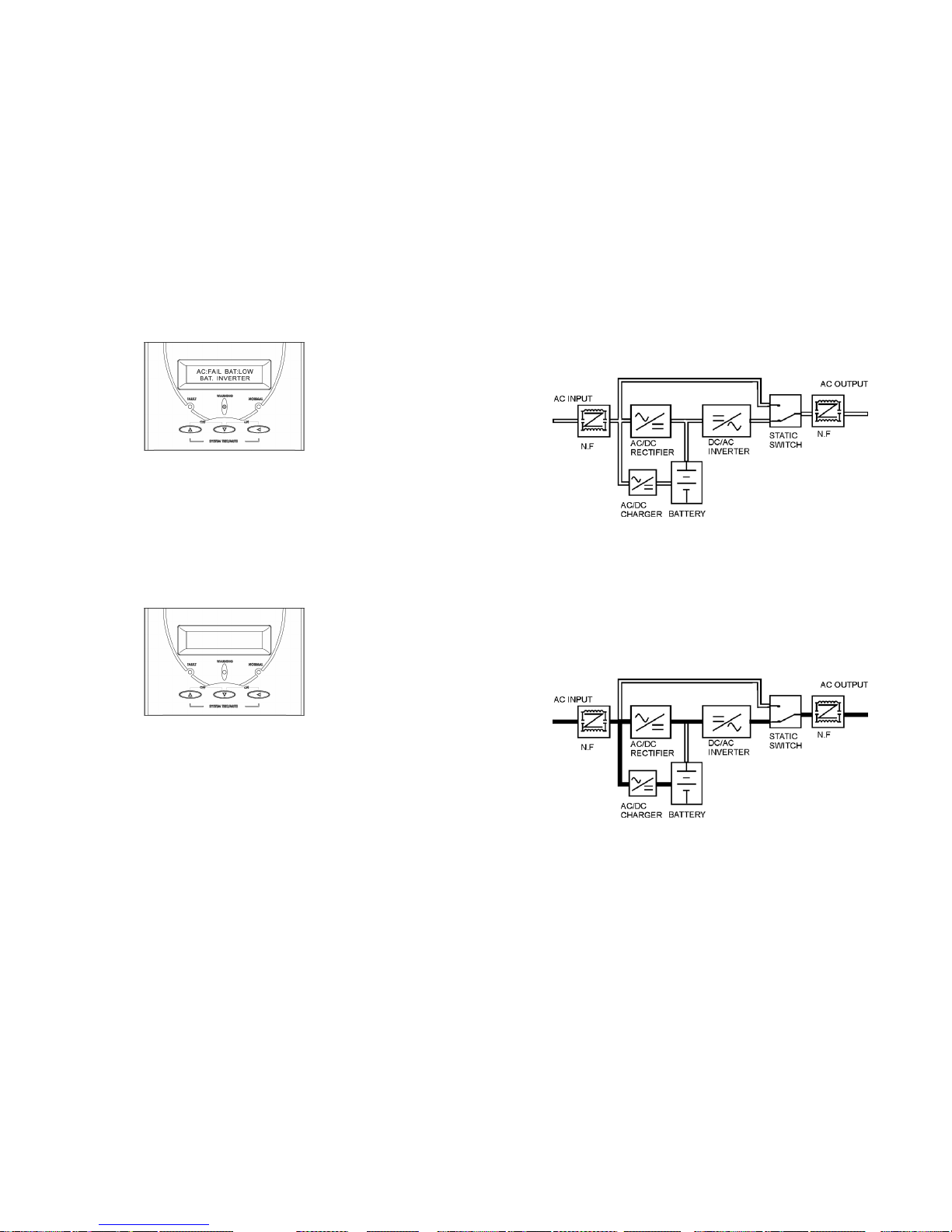
7. LED and LCD status as below:
UPS STATUS:
AC utility fails. The load is supplied by UPS in backup mode, and
battery power is approaching low level. Buzzer alarm beeps every
second.
ACTION: UPS will shut down automatically. Please save data soon.
8. LED and LCD status as below:
UPS STATUS:
AC utility power fails and battery runs out. UPS has shut down
automatically.
ACTION: UPS will restart up when AC utility power is restored. If AC
utility power failure is more than 6 hours, please follow storage
instruction.
23
7. OPERATION MODES OF THE UPS
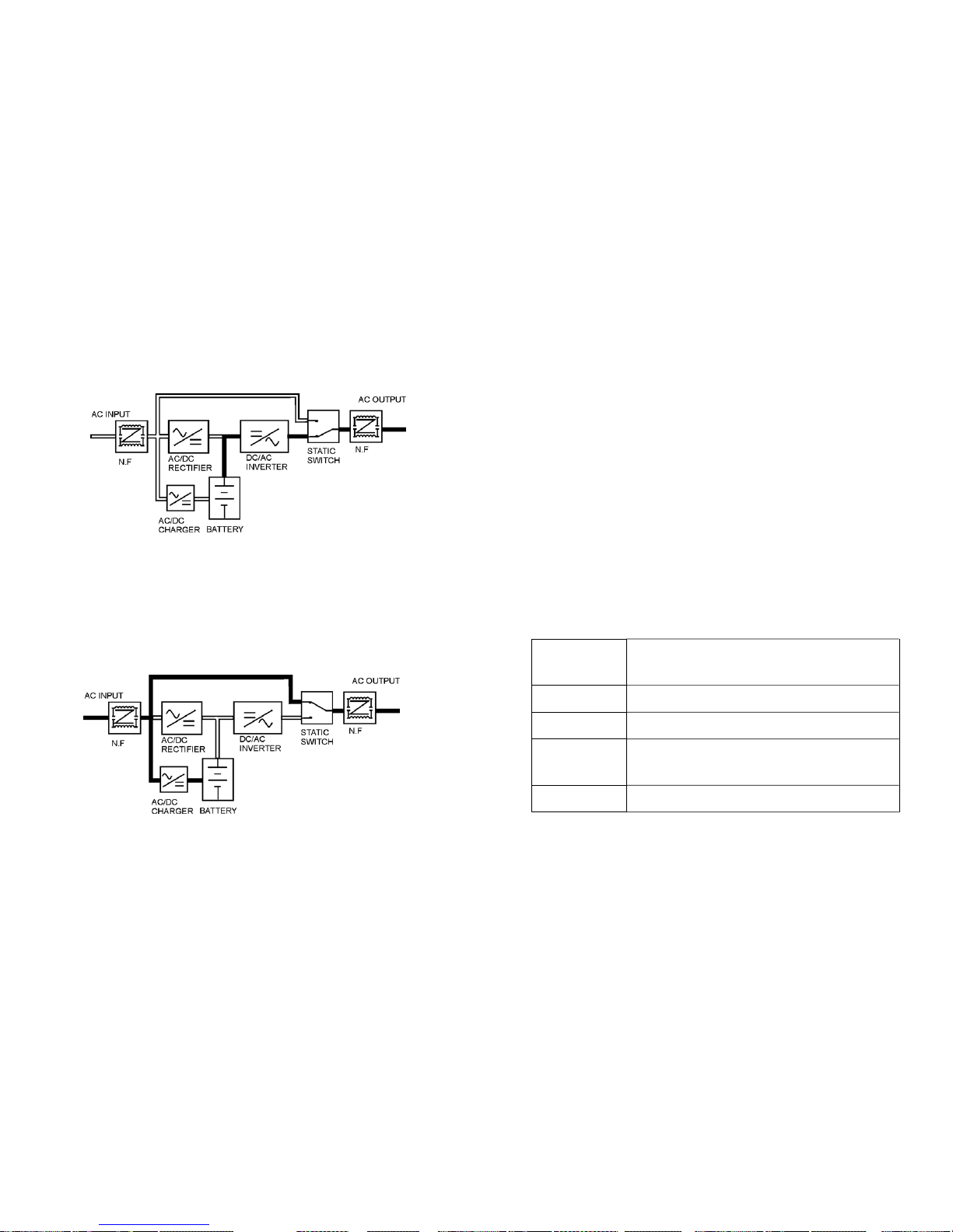
7.1 UPS System Block Diagram
7.2 Normal Operation
There are two main loops when AC utility is normal: the AC loop and the
battery charging loop. The AC output power comes from AC utility input and
passes through AC/DC rectifier, DC/AC inverter and static switch to support
power to load. The battery charging voltage comes from AC utility input and
converted by AC/DC charger to support battery-cha rging power.
Page 13
24
7.3 AC Utility Failure
The AC output comes from battery, passing through DC/AC inverter and
static switch within the battery backup time.
7.4 Bypass Enable
Under the following conditions, the bypass will be enabled:
1.Overload.
2.Inverter failure.
3.Over-temperature
25
8. COMPUTER INTERFACE
8.1 communication interface
The communication interface (DB9 port) on the back of the UPS may be
connected to a host computer. The port provides two different modes for
communicating with the computer like below.
1. Supply dry contact function (like RUPS of Megatec Company)
The port simulates relays closing to communicate with the computer. Its
major functions are as follows.
(1) To broadcast a warning when power fails.
(2) To close any open files before the battery exhausted out.
(3) To turn off the UPS.
2. Supply RS-232 for monitoring software (like RUPSII or UPSilon 2000 of
Megatec Company)
The UPS communicates with the computer by sending out RS-232 data
streams to one of the serial ports. By this method the user is able to monitor
the following parameters.
Input Voltage
Indicates the present input voltage to the UPS
system when AC power is present.
Output Voltage Indicates the present output voltage of the UPS.
AC Frequency Indicates the actual output frequency of the UPS.
Battery Voltage
Indicates the present DC voltage of the UPS
battery.
Temperature Indicates the actual temperature inside the UPS.
Page 14
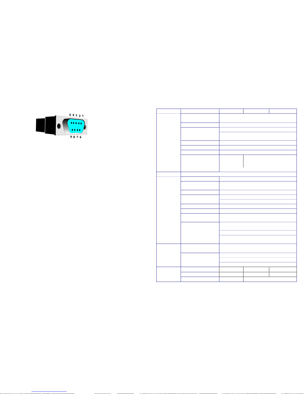
26
DB9 Interface Connector
DB9 PIN Assignment - 1K
PIN 1: UPS Fault
PIN 2: AC POWER Failure
PIN 3: Inverter Power On
PIN 4: Common GND of Pin 1,2,3,5,8
PIN 5: UPS Battery Low
PIN 6: Turn off UPS
PIN 7: GND of PIN6
PIN 8: inverter Output
PIN 9: RS232 TXD
DB9 PIN Assignment – 2K/3K
PIN 2: RS232 RXD
PIN 3: RS232 TXD
PIN 5: GND
The other PINs have no function.
27
9. SPECIFICATIONS
Rated Power Capacity 1KVA / 700W 2KVA / 1400W 3KVA / 2100W
Voltage
Single phase 220Vac, 160~300Vac at 70~100% load
140~300Vac at 50~70% load, 118~300Vac at 0~50% load
Frequency 50Hz or 60Hz +/- 4Hz
Input
Power Factor
≧ 0.95
Voltage, Frequency
Single phase 220Vac +/- 2% (230V or 240V re-settable via
LCD panel), 50Hz or 60Hz
Transient Response +/- 3% (100% load variation)
Waveform / Distortion Sine wave, THD < 3% at 0-100% linear load
Output
Crest Ratio 3 : 1
Voltage (longer backup
time is available upon
request)
7Ah / 12V * 3pcs 7Ah / 12V * 8pcs
Battery
Charger 5 hrs to 90% of full capacity after full load discharge
Transfer Time AC fail 0 ms; 2.5ms typical from inverter to bypass and vice versa
Battery Battery low shutdown and Fuse
Overload
125~150% 30sec, then switch to bypass and auto
re-transfer; >150% for 200ms
Short Circuit Current Limited and cut-off and fuse and breaker
Protection
EMI/EMC EN50091-2
Mains Failure Beeping every 4 seconds
Battery Low Beeping once every second
Audible Alarm
Fault, Overload Continuously
LCD
UPS status, I/P&O/P voltage& frequency, Battery voltage,
Battery capacity, Loading %, Temperature, History record
Indicator
LED Normal (green), Warning (yellow), Fault (red) LED
DB9 Connector RS-232 Interface; Power monitoring software (Option)
Communications
SNMP Intelligent Slot
Power management from SNMP manager and Web
browser (Option)
Network Surge Protection
RJ11 I/O port available for 10 base-T network
or Fax / Modem
Temperature 0-40 degree C; 32-104 degree F
Relative Humidity 0-95% non-condensing
Environment
Acoustic Noise Less than 45dBA (at 1 meter)
Net Weight (w/o batt.) 7kgs 13.5kgs 14.5kgs
Net Weight (w/ batt.) 14kgs 34kgs 35kgs
Physical
Dimension (WxHxD)mm 160x220x400 200x352x450
※ Specifications are subject to change without notice.
Page 15
28
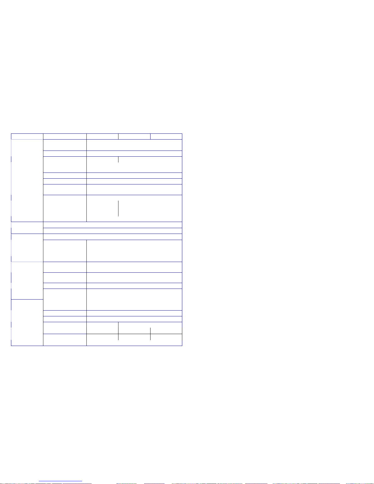
10. SPECIFICATIONS (Rack Mount Case)
Rated Power Capacity 1KVA / 700W 2KVA / 1400W 3KVA / 2100W
Voltage
Single phase 220Vac, 160~300Vac at 70~100% load
140~300Vac at 50~70% load, 118~300Vac at 0~50% load
Frequency 50Hz or 60Hz +/- 4Hz
Input
Power Factor
≧ 0.95 ≧ 0.97
Voltage, Frequency
Single phase 220Vac +/- 2% (230V or 240V re-settable via
LCD panel), 50Hz or 60Hz +/-0.5% (Battery mode)
Transient Response +/- 3% (100% load variation)
Waveform / Distortion Sine wave, THD < 3% at 0-100% linear load
Over Load Capacity
125~150% 30sec, then switch to bypass and auto
re-transfer; >150% for 200ms
Output
Crest Ratio 3 : 1
Voltage (longer backup
time is available upon
request)
7Ah / 12V * 3pcs
7Ah / 12V * 8pcs
Battery
Recharge Time 5 hrs to 90% of full capacity after full load discharge
Automatic: Overload and UPS failure
Bypass
By setting: Voltage Range 176V~ 253V+/-20V (re-settable via LCD panel)
Transfer Time AC fail 0 ms; 2.5ms typical from inverter to bypass and vice versa
Battery Mode
Beeping every 4 seconds (re-settable) and per second
when battery low
Overload > 125% Beeping twice per second
Audible Alarm
Fault Beep Continuously
LCD
UPS status, I/P&O/P voltage& frequency, Battery voltage,
Battery capacity, Loading %, Temperature, History record
Indicator
LED Normal (green), Warning (yellow), Fault (red) LED
DB9 Connector RS-232 Interface; Power monitoring software (Option)
Communications
SNMP Intelligent Slot
For Net Agent II / Mini (Option) with SNMP manager and
Web browser
Network Surge Protection
RJ11 I/O port available for 10 base-T network
or Fax / Modem
Temperature 0-40 degree C; 32-104 degree F
Relative Humidity 0-95% non-condensing
Environment
Acoustic Noise (at 1 M) < 45 dBA < 50 dBA
Net Weight (w/o batt.)
8.0 kgs 9.5 kgs 10.5 kgs
Net Weight (w/ batt.) 15.5 kgs N/A N/A
Physical
Dimension (WxHxD)mm 440 x 88 x 465
※ Specifications are subject to change without notice.
 Loading...