

Page 1
DOT MATRIX PRINTER
MODEL
iDP3410
Page 2

iDP3410 User's Manual
CITIZEN
Declaration of Conformity
Manufacturer's Name : Japan CBM Corporation
Manufacturer's Address :
CBM Bldg.,5-68-10, Nakano, Nakano-ku, Tokyo
164-0001, Japan
Declare the Product
Product Name : Dot Matrix Printer
Model Number (s) :
iDP3410
(iDP3410R/P, iDP3410S/C, iDP3410T/I)
(S.NO.98X0001 - )
Conform to the following Standards
LVD : EN60950 : 1992+A1+A2+A3+A4
EMC : EN55022 : 1994 Class A
EN61000-3-2 : 1995
EN61000-3-3 : 1995
EN50082-1 : 1992
IEC801-2 : 1991 4KV CD, 8KV AD
IEC801-3 : 1984 3V/m, 26MHz-1000MHz AM1KHz 80%
IEC801-4
: 1988 0.5KV Signal Line ± 1KV AC mains
Supplementary Information
"The product complies with the requirements of the Low Voltage Directive 73/23/EEC,
93/68/EEC and the EMC Directive 89/336/EEC, 92/31/EEC, 93/68/EEC"
Place : Tokyo, Japan
Date : September1995 Signature:
Full Name : Mikio Moriya
Position : General Manager
R & D Department
Europe Contact :
Norco Declaration AB
Box 7146 S-250 07 Helsingborg, Sweden
WARNING
This is a Class A products. In a domestic environment this product may cause radio interference in which case the user may be required to
take adequate measures.
ATTENTION
Ce produit de class A. Dans environement domestique, il peut causer des interférences radio. Auquel cas, l’utilisateur sera amené à prendre
les mesures adéquates.
Warnung
Dies ist ein Klasse A Produkt. In einer örtlichen Umgebung kann dieses Gerät Funkstörungen verusachen.
Atención
Este es un producto de la clase A. En ambientes domésticos éste producto puede causar radio Interferencias en cuyo caso el usuario de ber á
tomar las medldas oportunas.
VERWITTIGING
Dit is een klasse A produkt. Het gebruik hiervan kan radio interferenties veroorzaken die de gebruiker ertoe kunnen dwingen sommige
maatregelen te moeten treffen.
* THE ABOVE MENTIONED DECLARATION IS APPLIED ONLY FOR 230V MODEL.
Page 3

iDP3410 User's Manual
CITIZEN
IMPORTANT SAFETY INSTRUCTIONS
• Read all of these instructions and save them for future reference.
• Follow all warnings and instructions marked on the product.
• Unplug this product from the wall outlet before cleaning. Do not use liquid or aerosol cleaners. Use
a damp cloth for cleaning.
• Do not use this product near water.
• Do not place this product on an unstable cart, stand or table. The product may fall, causing serious
damage to the product.
• Slots and openings on the back or bottom of the case are provided for ventilation. To ensure reliable
operation of the product and to protect it from overheating, do not block or cover these openings. The
openings should never be blocked by placing the product on a bed, sofa, rug of other similar surface.
This product should never be placed near or over a radiator or heater. This product should not be
placed in an built-in installation unless proper ventilation is provided.
• This product should be operated from the type of power source indicated on the marking label. If you
re not sure of the type of power available, consult your dealer or local power company.
• Do not allow anything to rest on the power cord. Do not place this product where the cord will be
walked on.
• If an extension cord is used with this product, make sure that the total of the ampere ratings of the
products plugged into the extension cord does not exceed the extension cord ampere rating. Also,
make sure that the total of all products plugged into the wall outlet does not exceed 15 amperes.
• Never push objects of any kind into this product through cabinet slots as they may touch dangerous
voltage points or short out parts that could result in a r isk of fire or electr ic shock. Never spill liquid
of any kind on the product.
• Except as explained elsewhere in this manual, do not attempt to service this product by yourself.
Opening and removing the covers that are marked “Do Not Remove” may expose you to dangerous
voltage points or other risks. Refer all servicing on those compartments to service personnel.
• Unplug this product f rom the wall outlet and refer servicing to qualified service personnel under the
following conditions:
A. When the power cord or plug is damaged or frayed.
B. If liquid has been spilled into the product.
C. If the product has been exposed to rain or water.
D. If the product does not operate normally when the operating instructions are followed. Adjust
only those controls that are covered be the operating instructions since improper adjustment of
other controls may result in damage and will often require extensive work by a qualified
technician to restore the product to normal operation.
E. If the product has been dropped or the cabinet has been damaged.
F. If the product exhibits a distinct change in performance, indicating a need for service.
• Please keep the poly bag which this equipment is packed in away from children or throw it away to
prevent children from putting it on. Putting it on may cause suffocation.
Page 4

iDP3410 User's Manual
CITIZEN
WICHTIGE SICHERHEITSANWEI SUNGEN
• Lesen Sie die nachfolgenden Anweisungen sorgfältig durch und bewahren Sie sie auf.
• Befolgen Sie alle auf dem Drucker vermerkten Hinweise und Anweisungen. Vor dem Reinigen
grundsätzlich Stecker aus der Steckdose ziehen. Keine Flüssigkeiten oder Aerosolreiniger benutzen.
Nut mit einem feuchten Tuch abwischen.
• Der Drucker darf nicht in der Nähe von Wasser aufgestellt werden.
• Drucker nicht auf einem unstabilen Wagen, Stand oder Tisch aufstellen. Der Drucker könnte
herunterfallen und dabel beschädigt werden.
• Schlitze und Öffnungen im Gehäuse, in der Rückwand und im Boden dienen der Belüftung. Sie
dürfen keinesfalls zugedeckt oder blockiert werden, da sich der Dr uc ker sonst überhitzt. Drucker
nicht auf ein Bett, Sofa, Teppich oder dergleichen stellen. Drucker nicht in der Nähe eines
Heizkörpers aufstellen. Drucker darf nicht eingebaut werden, falls nicht für ausreichende Belüftung
gesorgt ist.
• Drucker nur mit der auf dem Typschild angegebenen Spannung betreiben. Wenn Sie sich nicht sicher
sind, fragen Sie ihren Händler oder ihr zuständiges Elektrizitätswerk.
• Nichts auf das Stromanschlußkabel stellen. Kabel muß so verlegt werden, daß man nicht darauftreten
kann.
• Ein etwaiges Verlängerungskabel muß der Stromstärke aller daran angeschlossenen Geräte
entsprechen.
• Keine Gegenstände in die Gehäuseschlitze schieben.
• Drucker darf nur da gewartet werden, wo im Handbuch angegeben, Öffnen und. Abnehmen von
Abdeckungen, die mit “Do not remove” gekennzeichenet sind, könnte gefährliche spannungführende
Stellen oder sonstige Gefahrenpunkte freilegen. Die Wa rtung solcher Stellen darf grundsätzlich nur
von besonders ausgebildetem Fachpersonal vorgenommen werden.
A. Wenn das Stromanschlußkabel oder der Stecker beschädigt oder durch-gescheuert ist.
B. Wenn Flüssigkeit auf dem Drucker verschüttet wurde.
C. Wenn der Drucker im Regen gestanden hat oder Wasser darauf verschüttet wurde.
D. Wenn der Drucker trotz genauer Befolgung der Betriebsvorschriften nicht richtig arbeitet. Nur die
in der Bedienungsanleitung angegebenen Einstellungen vornehmen. Ein Verstellen anderer
Bedienungselemente könnte den Drucker beschädigen und macht umständliche Arbeiten eines
qualifizierten Technikers erforderlich, um den Drucker Wieder auf den normalen Betrieb
einzustellen.
E. Wenn der Drucker heruntergefallen ist oder das Gehäuse beschädigt wurde.
F. Wenn der Drucker in seiner Leistung nachläßt.
• Bitte halten Sie den Kunststoffbeutel, in den die Ware verpackt ist, von Kindern entfernt, oder werfen
Sie ihn weg, damit er nicht in die Hande von Kindern gerät. Das Überstülpen des Beutels kann zum
Ersticken führen.
Lärmemis sion kleiner 70dBA
Page 5
iDP3410 User's Manual
CITIZEN
IMPORTANT: This equipment generates, uses, and can radiate radio frequency energy and if not installed and
used in accordance with the instruction manual, may cause interference to radio communications. It has been
tested and found to comply with the limits for a Class A computing device pursuant to Subpart J of Part 15 off
FCC Rules, which are designed to provide reasonable protection against such interference when operated in a
commercial environment. Operation of this equipment in a residential area is likely to cause interference, in
which case the user at his own expense will be required to take whatever measures may be necessary to correct
the interference.
CAUTION: Use shielded cable for this equipment.
Sicherheitshinweis
Die Steckdose zum Anschluß dieses Druckers muß nahe dem Grät angebracht und leicht zugänglich sein.
For Uses in Canada
This digital apparatus does not exceed the class A limits for radio noise emissions from digital, apparatus, as set
out in the radio interference regulations of the Canadian department of communications.
Pour L’utilisateurs
Canadiens
Cet appareil numérique ne dépasse pas les limites de carégorie a pour les émissions de bruit radio émanant
d’appareils numériques, tel que prévu dans les réglements sur l’interférence radio du départment Canadien des
communications.
Page 6

iDP3410 User's Manual
CITIZEN
<CAUTIONS>
1. Prior to using the equipment, be sure to read this User's Manual thoroughly. Please keep it handy for
reference whenever it may be needed.
2. The information contained herein may be changed without prior notice.
3. Reproduction of part or all of this User's Manual without permission is strictly prohibited.
4. Never service, disassemble, or repair parts that are not mentioned in this User's Manual.
5. Note that we will not be responsible for damages attributable to a user's incorrect operation/ ha ndling or an
improper operating environment.
6. Operate the equipment only as described in this User's Manual; otherwise accidents or problems may result.
7. Data are basically temporary; they cannot be stored or saved permanently or for a long time. Please note that
we will not be responsible for damages or losses of profit resulting f rom losses of the data attributable to
accidents, repairs, tests, and so on.
8. If you have any questions or notice any clerical errors or omissions regarding the information in this manual,
please contact our office.
9. Pl ease note tha t, no twiths tandin g Item 8 above, we will not be responsible for any effects resulting from
operation of the equipment.
Page 7
iDP3410 User's Manual
CITIZEN
SAFETY PRE CAUTIONS ----- BE SURE TO OBSERVE
In order to prevent hazards to an operator or other persons and damage to property, be sure to observe the
following precautions.
The following describes the degrees of hazard and damages that can occur if the given instructions are
neglected or the equipment is incorrectly operated.
WARNING Negligence of this precaution may result in death or serious injury.
CAUTION Negligence of this precaution may result in injury or damage to property.
This is an illustration mark used to alert your attention.
This is an illustration mark used to indicate such information as an instruction or the like.
Page 8
iDP3410 User's Manual
CITIZEN
WARNING !
Never handle the equipment in the following manners, as it may break, become out of order, or overheat
causing smoke and resulting in fire or electric shock.
If the equipment is used in an abnormal condition, such as when broken, then problems, smoke emission,
abnormal odor/noise, and fire can result. If an abnormal condition exists, be sure to turn off the power,
disconnect the power plug from a plug socket, and contact our dealer. Never repair the equipment on your
own - it is very dangerous.
• Do not allow the equipment to receive a strong impact or shock, such as kicking, stomping, hitting,
dropping, and the like.
• Install the equipment in a well-ventilated place. Do not use it in such a manner that its ventilation port will
be blocked.
• Do not install the equipment in a place like a laboratory where chemical reactions are expected, or in a place
where salt or gases are contained in the air.
• Do not connect/disconnect a power cord or a data cable, while holding the cable. Do not pull, install, use, or
carry the equipment in such a manner that force will be applied to the cables.
• Do not drop or insert any foreign substances, such as clips or pins, into the equipment.
• Do not spill any liquid or spray any chemical-containing liquid over the equipment. If any liquid is spilled
on it, turn off the power, disconnect the power cable and power cord from the plug socket, and so on, and
contact our dealer.
• Do not disassemble or remodel the equipment. Negligence of this may cause fire or electric shock.
• Should you drop or break this AC adapter by any chance, unplug it immediately and contact our office.
Using it in that condition may result in fire or electric shock.
• Should water enter inside the equipment by any chance, unplug it and contact our office. Using it in that
condition may result in fire or electric shock.
• Use the equipment only with the specified commercial power supply. Negligence of this may result in fire,
electric shock, or problems.
• Do not damage, break, process, bend/pull by force, twist, or bundle an AC adapter cord. Also, do not put a
heavy substance on it or heat it. The AC adapter could be broken, resulting in fire, electric shock, or trouble.
If the AC adapter cord is damaged, contact our office.
• Do not connect/disconnect the AC adapter with wet hands. It may result in electric shock or other problems.
• Do not overload a single electrical outlet, using a table tap or a current tap socket. I t may result in fire or
electric shock.
An equipment packing bag must be discarded or kept away from children. A child can suffocate if the bag
is placed over the head.
Page 9

iDP3410 User's Manual
CITIZEN
PRECAUTIONS FOR INSTALLATION
• Do not use or store the equipment in a place exposed to fire, moisture, or direct sunlight, or in a place near a
heater or a thermal device where the prescribed operating temperature and humidity are not met, or in a
place exposed to much oil, iron powder, or dust. The equipment may beco me out of order, emit smoke, or
catch fire.
• Do not install the equipment in a place like a laboratory where chemical reactions are expected, or in a place
where salt or gases are contained in the air. There is a danger of fire or electric shock.
• Do not put any object on the printer. It may cause trouble.
• Do not use the equipment near a radio or TV receiver. Do not share the power from a plug socket a radio or
TV receiver is connected to. It may cause a reception problem.
• Use the equipment only at the specified voltage and frequency. Otherwise, it may emit smoke and catch fire
or cause other problems.
• Confirm that a plug socket used for connection has sufficient capacity.
• Do not overload a single electrical outlet in connecting the power cable. It may result in the cable catching
fire or a power outage. Also, do not stamp or put any object on the cable.
• Never connect a grounding cable to a gas pipe. There is a danger of explosion. When connecting or
disconnecting the grounding cable, be sure to disconnect the power plug from the plug socket.
• When connecting/disconnecting the cables, be sure to turn off the power first, including the connected side,
and then connect/disconnect them, holding a plug and a connector. Do not pull or carry the equipment with
a load applied to the cable.
• Connect a connector cable securely. If a reverse-polarity connection is made, internal elements may be
broken or a mating device may be adversely affected.
• Use a shielding wire or twisted pair wire for a signal line, in order to minimize noise effect. Avoid
connecting to a device that is likely to generate noise.
• When a drawer kick connector is provided, do not connect any device other than the prescribed solenoid
specifications. Negligence of this could cause trouble.
• Use the equipment in an environment where there is a plug socket near the main body and you can easily
disconnect the power plug from it, to shut off the power.
• When the equipment will not be used for a long period of time, unplug it.
• When transporting the equipment, remove the rolled paper from it.
• Install the equipment on a flat, stable desk in a well-ventilated place free from vibrations. (Do not block the
ventilation port.)
Page 10
iDP3410 User's Manual
CITIZEN
PRECAUTIONS FOR HANDLING
Do not handle the equipment in the following manners, because problems may result.
• Do not use a power supply other than the specified AC adapter.
• Do not print when there is no recording paper or ink ribbon set in the equipment. The print head may be
damaged
• Be careful not to drop foreign substances, such as clips, pins, and screws, into the main body.
• Do not spill any liquid or spray any chemical-containing liquid over the equipment.
• Do not stamp on, drop, hit, or give a strong shock to the equipment.
• Never use a pointed object, such as a pen, to operate the operation panel.
• Do not use Scotch tape to fasten paper together for continuous use.
• Never pull the set paper forcibly. When opening/closing the printer cover, take care that the p aper w ill not
be caught.
To Prevent Injury and Spreading of Damage
• Do not touch the printing part of the print head.
• When turning on the power, do not touch the moving parts, such as a cutter and gear inside the main body,
or electric parts.
• Be careful to avoid bodily injure or damaging other objects with an edge of sheet metal.
• Should any error occur while operating the equipment, stop it immediately and disconnect the power plug
from the plug socket.
• Should a problem occur, leave solving it to our serviceman. Do not disassemble the equipment on your
own.
• When opening/closing the cover, and so on, be careful not to catch your hand or finger on the equipment.
Page 11
iDP3410 User's Manual
CITIZEN
DAILY MAINTENANCE
• Prior to starting maintenance work, be sure to turn off the main body.
• Use a dry soft cloth to wipe off stains and dust from the surfaces of the main body case. For severe soiling,
dip the cloth in water and wring it, for wiping off the soil. Never use organic solvents, such as a lcohol,
thinner, trichlene, benzene, ketone, or chemical dusters.
• If the equipment is contaminated with paper powder, use a soft brush to clean it.
Page 12

iDP3410 User's Manual
CITIZEN
CONTENTS
1. OUTLINE...............................................................................................................................................1
1.1 Features.......................................................................................................................................................... 1
1.2 Unpacking...................................................................................................................................................... 1
2. BASIC SPECIFICATIONS.....................................................................................................................2
2.1 Model Classification....................................................................................................................................... 2
2.2 Basic Specifications........................................................................................................................................ 3
2.3 Paper Specification......................................................................................................................................... 4
2.3.1 Recommended Paper............................................................................................................................... 4
2.3.2 Printing Position...................................................................................................................................... 4
2.3.2 Cutter Layout........................................................................................................................................... 4
3. OUTER APPEARANCE AND COMPONENT PARTS .........................................................................5
4. OPERATION..........................................................................................................................................6
4.1 Connecting AC Adapter................................................................................................................................. 6
4.2 Connecting Interface Cable............................................................................................................................ 7
4.3 Connecting Drawer Kick-Out Connector....................................................................................................... 7
4.4 Setting the Cassette Ribbon............................................................................................................................ 8
4.5 Inserting the Paper.......................................................................................................................................... 9
4.6 How to Remove Remaining Paper Roll........................................................................................................11
4.7 Removing Paper Jam.................................................................................................................................... 11
4.8 Operation Panel and Display of Error .......................................................................................................... 12
4.9 Operation Flow at Power-on......................................................................................................................... 13
5. DIP SWITCH SETTING.......................................................................................................................14
5.1 Location of DIP Switch................................................................................................................................ 14
5.2 DIP Switches Setting.................................................................................................................................... 15
6. PRESET JUMPER SETTING..............................................................................................................17
6.1 Location of Preset Jumper............................................................................................................................ 17
6.2 Preset Jumper Table...................................................................................................................................... 17
7. MODE SETTING METHOD.................................................................................................................18
8. INPUT BUFFER BACKUP FUNCTION ..............................................................................................19
8.1 Buffer Size.................................................................................................................................................... 19
8.2 Input Buffer Backup..................................................................................................................................... 19
8.3 Clearing the Input Buffer.............................................................................................................................. 19
9. PARALLEL INTERFACE.....................................................................................................................20
9.1 Specifications............................................................................................................................................... 20
9.2 Connector's Pin Configuration ..................................................................................................................... 20
9.3 Input and Output Signals.............................................................................................................................. 21
9.3.1 Input and Output Signals....................................................................................................................... 21
9.3.2 Electrical Characteristics....................................................................................................................... 22
9.3.3 Timing Chart......................................................................................................................................... 23
9.3.4 Data Receiving Control......................................................................................................................... 23
10. SERIAL INTERFACE ........................................................................................................................24
10.1 Specifications............................................................................................................................................. 24
10.2 Connector's Pin Configuration ................................................................................................................... 25
10.3 Input and Output Signals............................................................................................................................ 26
10.3.1 Input and Output Signals..................................................................................................................... 26
10.3.2 Data Configuration............................................................................................................................. 28
10.3.3 Error Detection.................................................................................................................................... 29
10.3.4 Data Receiving Control....................................................................................................................... 29
10.3.5 Buffering ............................................................................................................................................. 29
10.3.6 Electrical Characteristics..................................................................................................................... 30
Page 13

iDP3410 User's Manual
CITIZEN
11. DRAWER KICK-OUT CONNECTOR AND POWER CONNECTOR................................................31
11.1 Specifications of Drawer Kick-Out Connector...........................................................................................31
11.2 Connector's Pin Configuration ................................................................................................................... 31
11.3 Drive Circuit............................................................................................................................................... 31
11.4 Specifications of Power Supply Connector................................................................................................ 32
12. MAINTENANCE AND SERVICE ......................................................................................................33
13. PRINT CONTROL FUNCTIONS.......................................................................................................34
13.1 CBM Mode................................................................................................................................................. 34
13.1.1 Command List..................................................................................................................................... 34
13.1.2 Description of Items............................................................................................................................ 35
13.2 STAR Mode................................................................................................................................................ 52
13.2.1 Command List..................................................................................................................................... 52
13.3 ESC/POS Commands................................................................................................................................. 83
13.3.1 Command List..................................................................................................................................... 83
14. CHARACTER CODES TABLE .......................................................................................................104
14.1 CBM (Domestic)...................................................................................................................................... 104
14.2 CBM (International)................................................................................................................................. 105
14.3 STAR (Domestic)..................................................................................................................................... 106
14.4 STAR (International)................................................................................................................................ 107
14.5 Code Page 437.......................................................................................................................................... 108
14.6 Katakana................................................................................................................................................... 109
14.7 Code Page 850.......................................................................................................................................... 110
14.8 Code Page 860.......................................................................................................................................... 111
14.9 Code Page 863.......................................................................................................................................... 112
14.10 Code Page 865........................................................................................................................................ 113
14.11 Code Page 852........................................................................................................................................ 114
14.12 Code Page 866........................................................................................................................................ 115
14.13 Code Page 857........................................................................................................................................ 116
14.14 Windows Code ....................................................................................................................................... 117
14.15 International Character Codes Table ...................................................................................................... 118
APPENDIX 1. BLOCK DIAGRAM........................................................................................................119
APPENDIX 2. OUTLINE DRAWING.....................................................................................................120
Page 14

iDP3410 User's Manual
CITIZEN
<<<German>>>
4. BETRIEB...........................................................................................................................................128
4.1 Anschluß des Netzteils............................................................................................................................... 128
4.2 Anschluß des Schnittstellenkabels ............................................................................................................. 129
4.3 Anschluß des Ausschubmechanismussteckers der Geldschublade ............................................................ 129
4.4 Einsetzen der Farbbandkassette.................................................................................................................. 130
4.5 Einlegen der Papierrolle ............................................................................................................................. 131
4.6 Entfernen des restlichen Druckpapiers....................................................................................................... 133
4.7 Beseitigung von Papierstaus....................................................................................................................... 133
4.8 Bedienfeld und Fehleranzeigelämpchen.....................................................................................................134
4.9 Betriebsfluß beim Einschalten.................................................................................................................... 135
5. DIP-SCHALTER-EINSTELLUNG.....................................................................................................136
5.1 Lage der DIP-Schalter................................................................................................................................ 136
5.2 DIP-Schalter-Einstellungen........................................................................................................................ 137
6. EINSTELLUNG DER VORWAHL-JUMPERSTECKER....................................................................139
6.1 Lage der Vorwahl-Jumperstecker............................................................................................................... 139
6.2 Vorwahl-Jumperstecker-Tabelle ................................................................................................................. 139
7. METHODE FÜR MODUSEINSTELLUNG........................................................................................140
12. WARTUNG UND DIENST...............................................................................................................141
Note:
CITIZEN, CITIZEN logo are registered trademark of CITIZEN WATCH CO., LTD.
ESC/POS and EPSON are a trademark and registered trademark of SEIKO EPSON Corporation.
STAR is a registered trademark of Star Micronics Corporation.
Windows is a registered trademark of Microsoft Corporation.
Page 15

iDP3410 User's Manual
1 CITIZEN
1. OUTLINE
This is a small-size dot impact printer developed for various data communication terminals, POS terminals,
kitchen-use printers, bank card, terminals, and so on.
Its abundant built-in features allow you to widely use this printer for different applications. Prior to using it, read
and understand this manual thoroughly.
1.1 Features
(1) Small size, light weight, and low price
(2) High-speed print (Bi-directional)
(3) Red and black print
(4) Very easy paper loading by the auto loading function
(5) Paper end detecting function
(6) Power supply through an AC adapter
1.2 Unpacking
(1) When unpacking the printer, confirm that the following parts are provided.
• Printer body 1 unit
• Cassette ribbon 1 piece
• Sample paper roll 1 roll
• AC adapter 1 piece
• User's manual 1 copy
CAUTION : • Install the printer on a flat and stable desk.
• Do not install the printer near a heater or in a place exposed to direct sunlight.
• Do not use the printer in a high-temperature, high-humidity, and contaminated
environment.
• Do not allow dew condensation on the printer. If dew is condensed on it, leave the
power turned off until dew condensation is gone.
Page 16

iDP3410 User's Manual
2 CITIZEN
2. BASIC SPECIFICATIONS
2.1 Model Classification
The printer model is classified by the following designation method.
iDP3410 - R F 120
Model Name
♦ Exclusive AC Adapter Types and Power Cords
• 34AD-U (120 V 2-core cord)
• 34AD-E (230 V 2-core cord)
AC adapter
120: For 120 V AC
230: For 230 V AC
Character Set
F: International
Interface
CBM Mode
R: Serial(RS-232C D-Sub)
P: Parallel(CENTRONICS-based)
STAR Mode
S: Serial(RS-232C mini DIN)
C: Parallel(CENTRONICS-based)
ESC/POS Mode
T: Serial(RS-232C D-S ub)
I: Parallel(CENTRONICS-based)
Page 17
iDP3410 User's Manual
3 CITIZEN
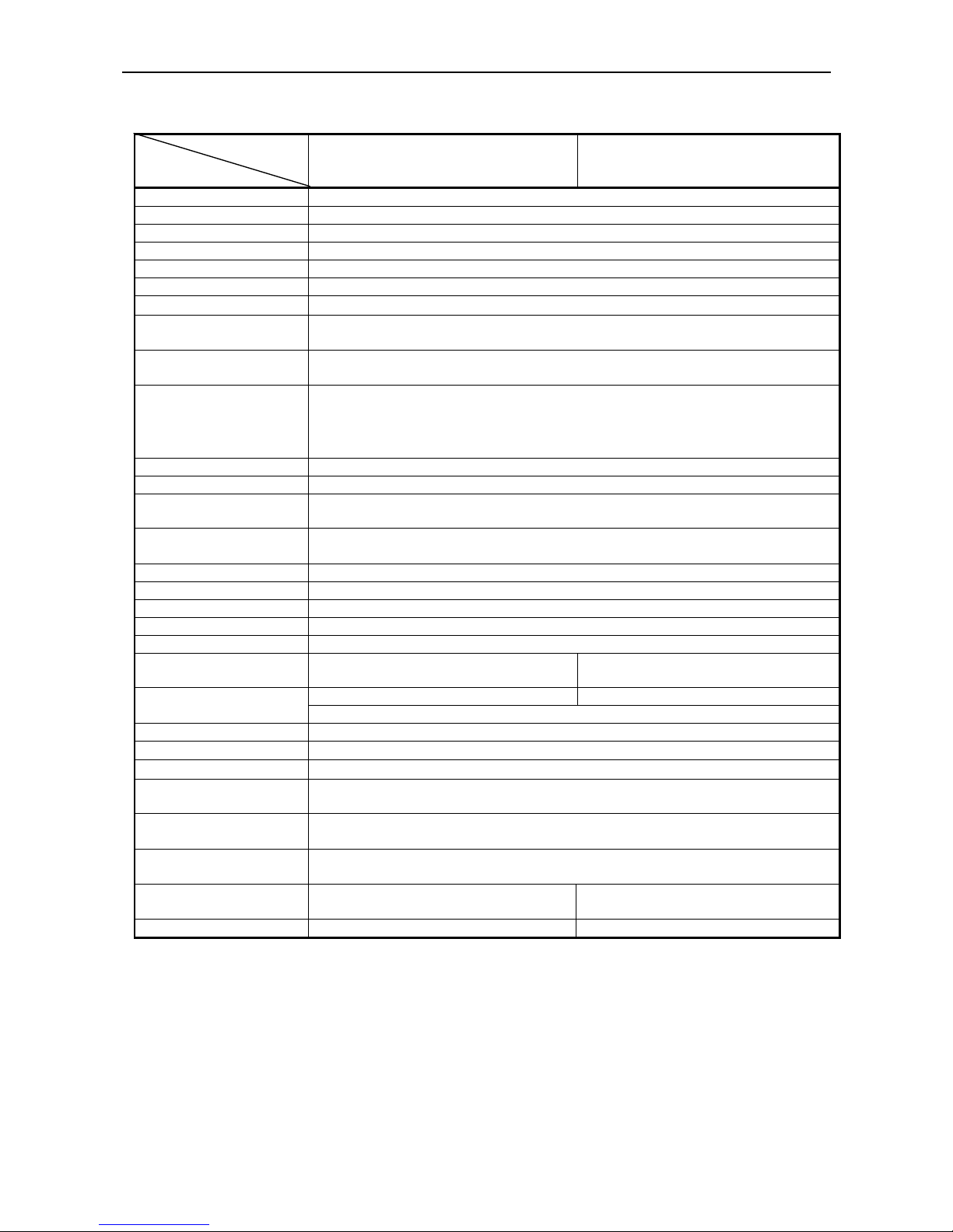
2.2 Basic Specifications
Model
Item
iDP3410-*F120 iDP3410-*F230
Printer mechanism DP-410 Series (CITIZEN)
Print method Serial dot impact method (Bi-directional print)
Print width 64 mm
Print head 9 pins
Print speed Approx. 3 lines/sec. (At single-color continuous print)
Print columns 40 columns or 42 columns (Selectable with the DIP switch)
Character size
1.31 mm (W)×3.1 mm (H)
Character types Alphanumeric, International characters, Code page 850, 860, 863, 865, 852, 866,
857; Windows code
Line spacing 4.23 mm(1/6 inch) or 2.82(1/9 inch);
Minimum paper feed pitch 1.41 mm(1/18 inch)
Paper
Ordinary paper and non-carbon paper 76+/-0.5 mm (W)×φ83 mm (O.D.);
Single-sheet paper: 45 to 55 kg/1,000 sheets/1,091×788 mm
Copying paper: Non-carbon paper, 1 original + 1 copy, Tota l thickness 0.2 mm or
less
Ink ribbon Special purpose ribbon cartridge, Red/black or single color(black)
Interface Serial (RS-232C), Parallel (CENTRONICS compliant)
Command system
CBM mode, STAR mode, ESC/POS mode
The user can select the mode with the DIP switches and preset jumpers.
Print function Provided by operating the on-line, self-test, hex dump print function power
switches and FEED switch
Input buffer 6 KB or 256 bytes (Selectable with the DIP switch)
Buffer backup Within 24 hours (After 10 minutes or more of printer operation)
Drawer 2-drawer or 1-drawer switch
Auto loading
Equipped (Automatically feeds the paper by several lines when it is inserted.)
Paper end detection Equipped (Stops printing when the paper runs out.)
Supply voltage 120 V AC +/- 10 %,
50/60 Hz
230 V AC +/- 10 %,
50/60 Hz
34AD-U 34AD-EAC adapter
Output: 26 V DC, 1.15 A
Power consumption Not printing: Approx. 8 W Printing: Approx. 30 W
W eight Main body: 1.25 kg AC adapter: 0.95 kg
Outer dimensions
144 (W) × 233 (D) × 121 (H) mm
Operating temperature and
humidity
0∼40 °C, 35∼85 % RH (No dew condensation)
Storage temperature and
humidity
-20∼60°C, 10∼90 % RH (No dew condensation)
Reliability Print head: 80,000,000 characters
Mechanism: MCBF 2,500,000 lines
EMI standard
FCCA
EN55022 Class-A
CE Marking
Safety Standard *1 TUV GS
*1.The AC adapter alone has acquired the Electric Appliances Control Act, UL Standard, C-UL Standard, and
TUV GS Standard.
Page 18
iDP3410 User's Manual
4 CITIZEN
2.3 Paper Specification
2.3.1 Recommended Paper
• Type : Normal paper and non-carbon paper
• Paper width : 76 +/- 0.5 mm
• Paper thickness : Single-sheet paper --- 45∼55 kg / 1,000 sheets / 1,091 x 788 mm;
Copying paper --- Non-carbon paper, 1 original + 1 copy,
Total thickness 0.2 mm or less
• Roll diameter : φ83 mm or less
• Core : φ12 mm (Inner Diameter), φ18 mm (Outer Diameter)
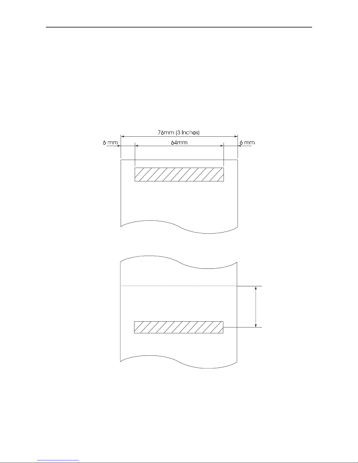
2.3.2 Printing Position
2.3.2 Cutter Layout
Approx. 20 mm
Cutting Position
Page 19
iDP3410 User's Manual
5 CITIZEN
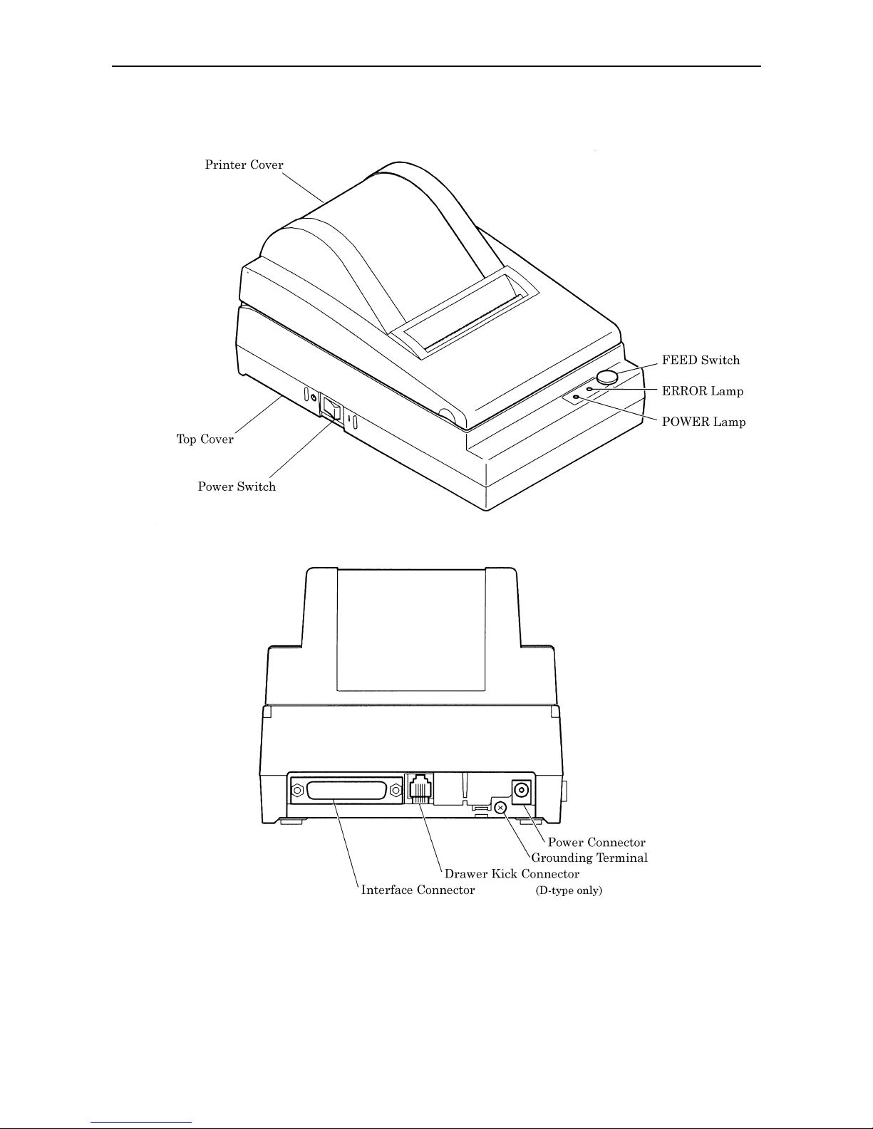
3. OUTER APPEARANCE AND COMPONENT PARTS
Page 20
iDP3410 User's Manual
6 CITIZEN
4. OPERATION
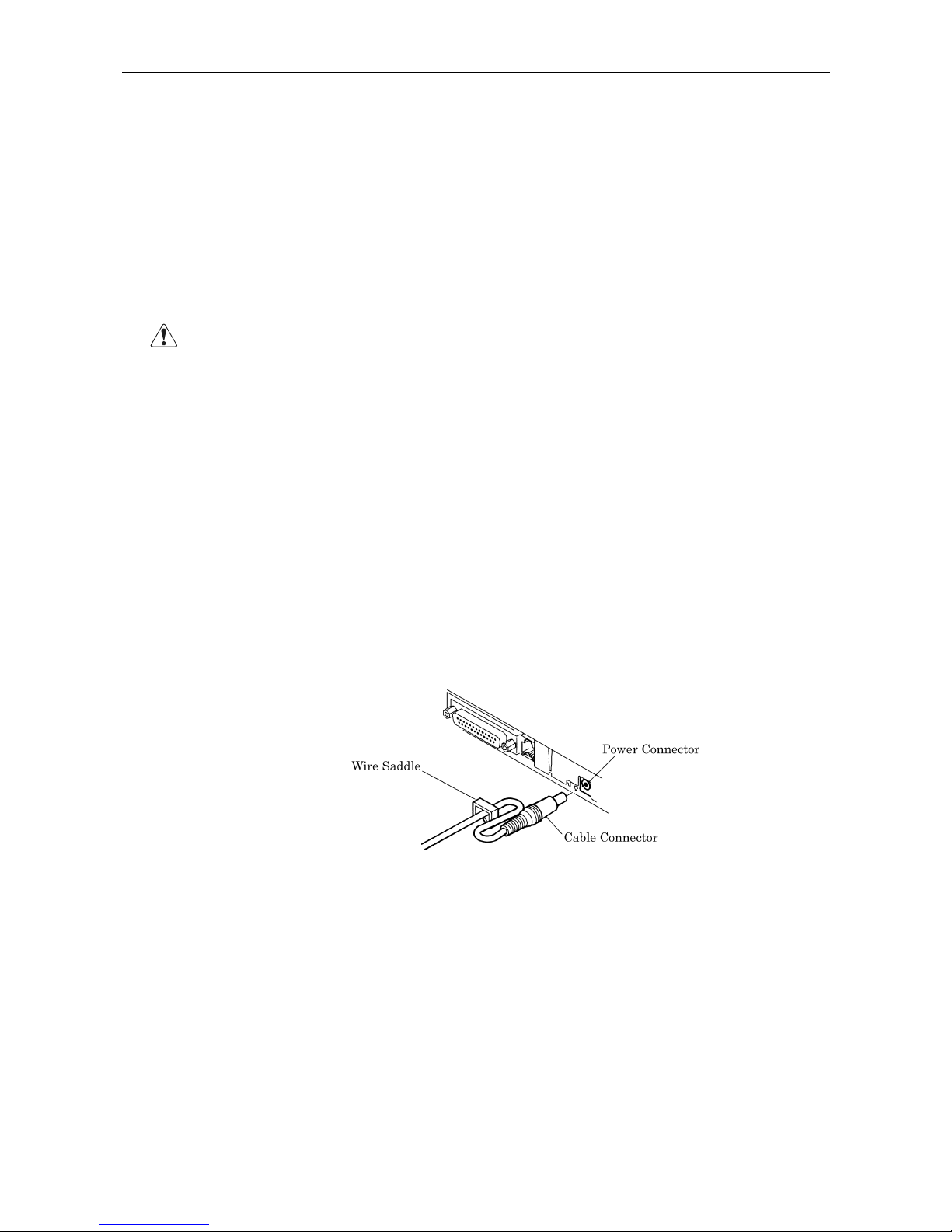
4.1 Connecting AC Adapter
(1) Turn off the Power switch.
(2) Connect the cable connector of the AC adapter to the power connector located on the back of the printer.
(3) In order to prevent disconnection of the cable connector, put it through a wire saddle, as shown in the
figure below.
(4) Connect the AC power cord plug to a plug socket.
CAUTION : • Use only the specified AC adapter.
• Use a different AC power supply from one used for any noise-generating device.
• Do not use the accessory AC adapter for another device or application besides this
equipment.
• When disconnecting the AC adapter, be sure to hold the AC adapter itself or the plug.
Do not pull its cord.
• Pulling an AC adapter cord will damage it and may result in fire, electric shock, or
snapping of the wire.
• If lightning is occurring in the area, disconnect the AC adapter from the plug socket
and do not use the equipment. A lightning strike could result in fire or electric shock.
• Do not put the AC adapter cord near any thermal device. The coating of the power
cord can melt, resulting in fire or electric shock.
• When the printer is not used for a long period of time, be sure to disconnect the AC
adapter from the plug socket, for safety.
Page 21
iDP3410 User's Manual
7 CITIZEN
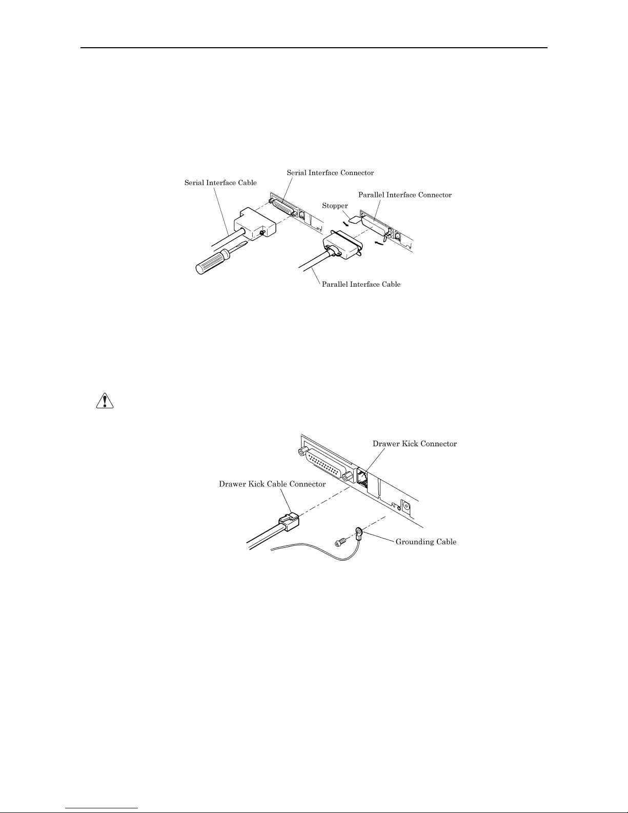
4.2 Connecting Interface Cable
(1) Turn off the power. (Mating side included)
(2) Check the top and bottom of the cable terminals, and connect to the interface connector.
(3) Fix the cable terminals.
• Serial Interface: Tighten screws, to fix.
• Parallel Interface: Turn a stopper, to fix.
(4) Connect the cable to a computer.
4.3 Connecting Drawer Kick-Out Connector
(1) Turn off the power.
(2) Chec k the top and bottom of the drawer kick-out cable connector, and connect it to the drawer kick-out
connector located on the back of the printer.
(3) Screw the grounding cable of the drawer to the grounding terminal of the printer.
CAUTION : Connect only the prescribed drawer (Solenoid) to the drawer kick-out connector.
Page 22
iDP3410 User's Manual
8 CITIZEN
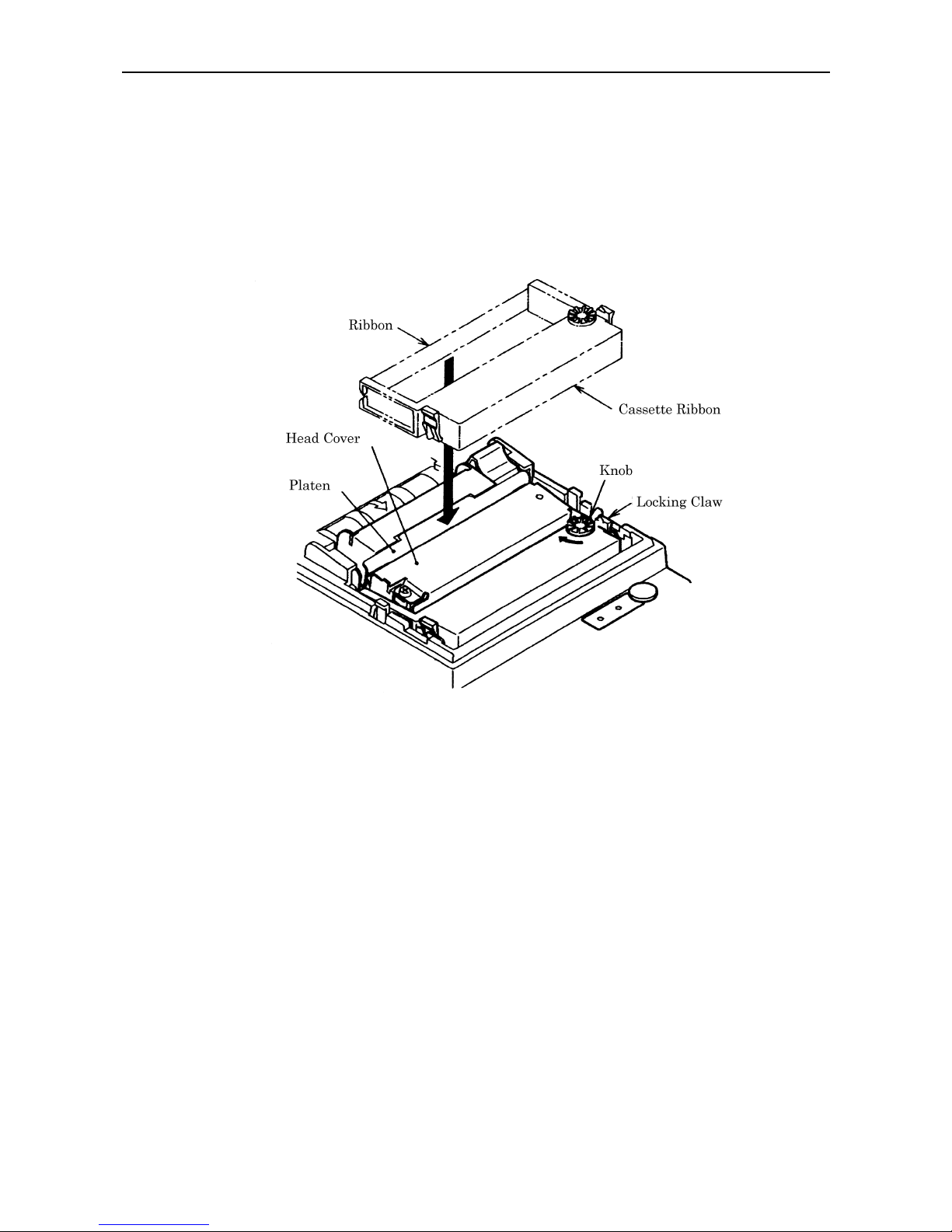
4.4 Setting the Cassette Ribbon
(1) Open the printer cover.
(2) If the ribbon is slackened, turn the knob in the arrow-indicated direction to give the tension to it before
setting.
(3) W hile putting the ribbon in between the head cover and platen, push the locking claws into the holder of
the printer.
(4) Turn the knob of the cassette ribbon in the arrow-indicated direction to eliminate slackness of the ribbon.
(5) To remove the cassette ribbon, lift it while tilting the locking claws on both sides toward the inside.
Page 23
iDP3410 User's Manual
9 CITIZEN
4.5 Inserting the Paper
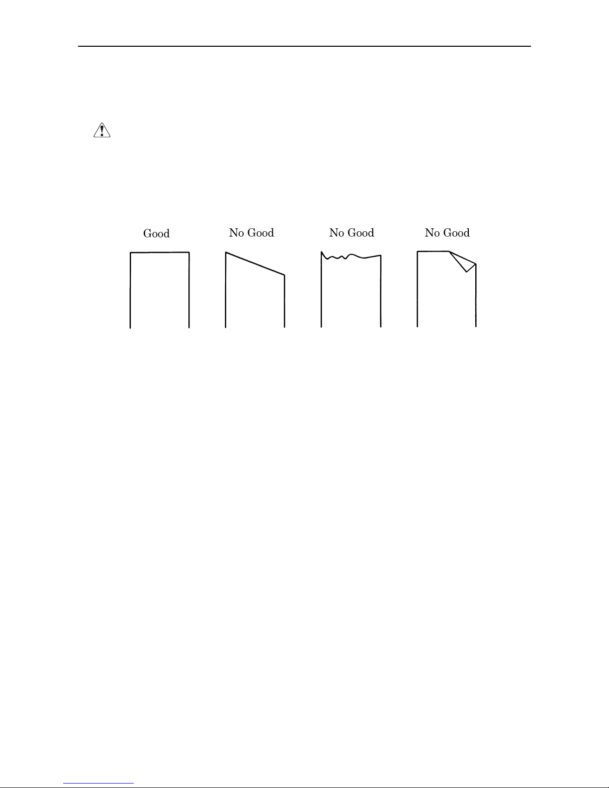
(1) Put your hands in the concave parts on both sides of the printer cover, and open it until it comes to a stop.
(2) Cut the end of the paper roll at close to a right angle.
CAUTION : • Be sure to use the specified paper roll.
• Use of unspecified paper may adversely affect print quality, printer service life, and so
on.
• The printer cover is not detachable. Do not apply an excessive force beyond its
stopping position.
• Do not insert a frayed or bent end of paper into the printer.
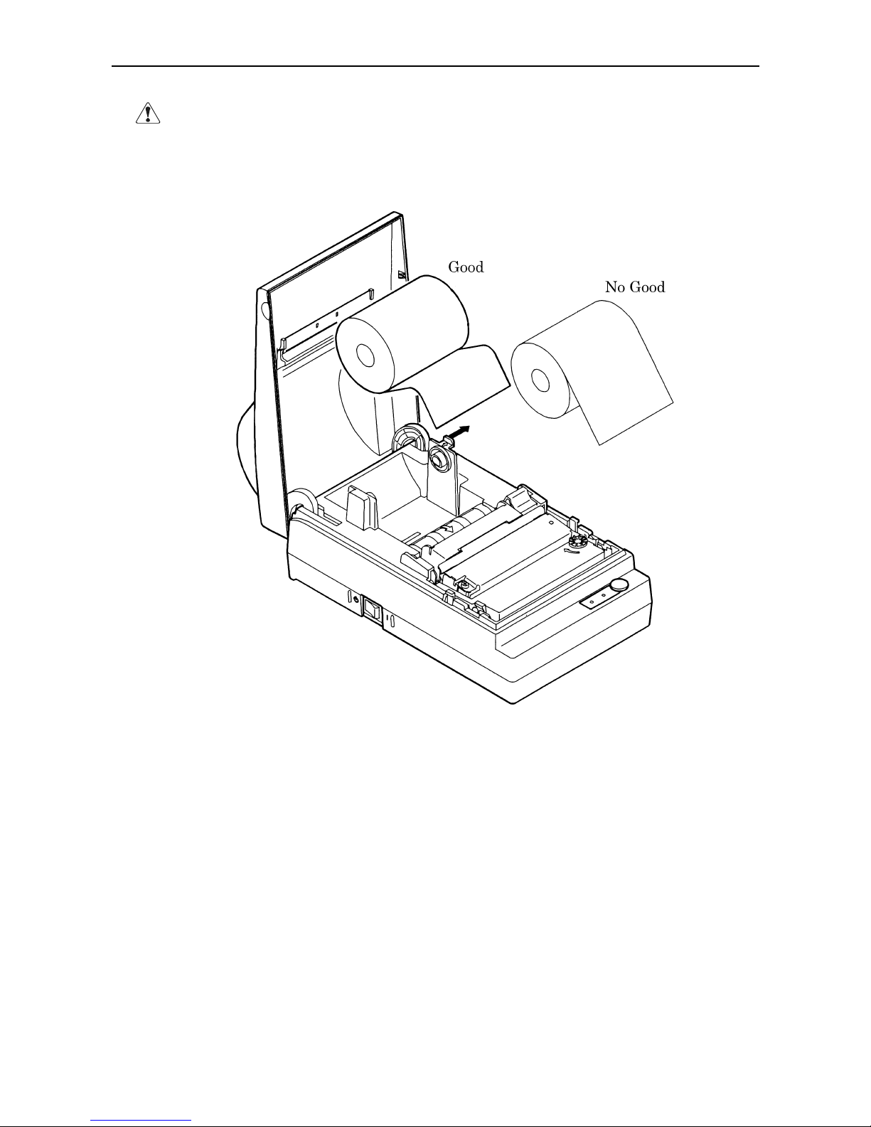
(3) Check the winding direction of the paper roll.
(4) Opening the paper holder, support the center of the paper roll correctly.
(5) Turn on the printer.
(6) Insert the end of the paper roll straight into the paper inlet slot (Indicated by an arrow on the case).
(7) The paper is automatically fed in and comes out of the paper outlet slot of the printer.
(8) Close the printer cover and cut the surplus paper with a tear bar.
Page 24
iDP3410 User's Manual
10 CITIZEN
CAUTION : • If the paper is slack, rewind it, to remove the slack.
• If the paper is set slantwise, operate the paper-free lever, to correct the paper position.
• While printing, do not hold the paper. This can cause a paper jam.
Page 25
iDP3410 User's Manual
11 CITIZEN
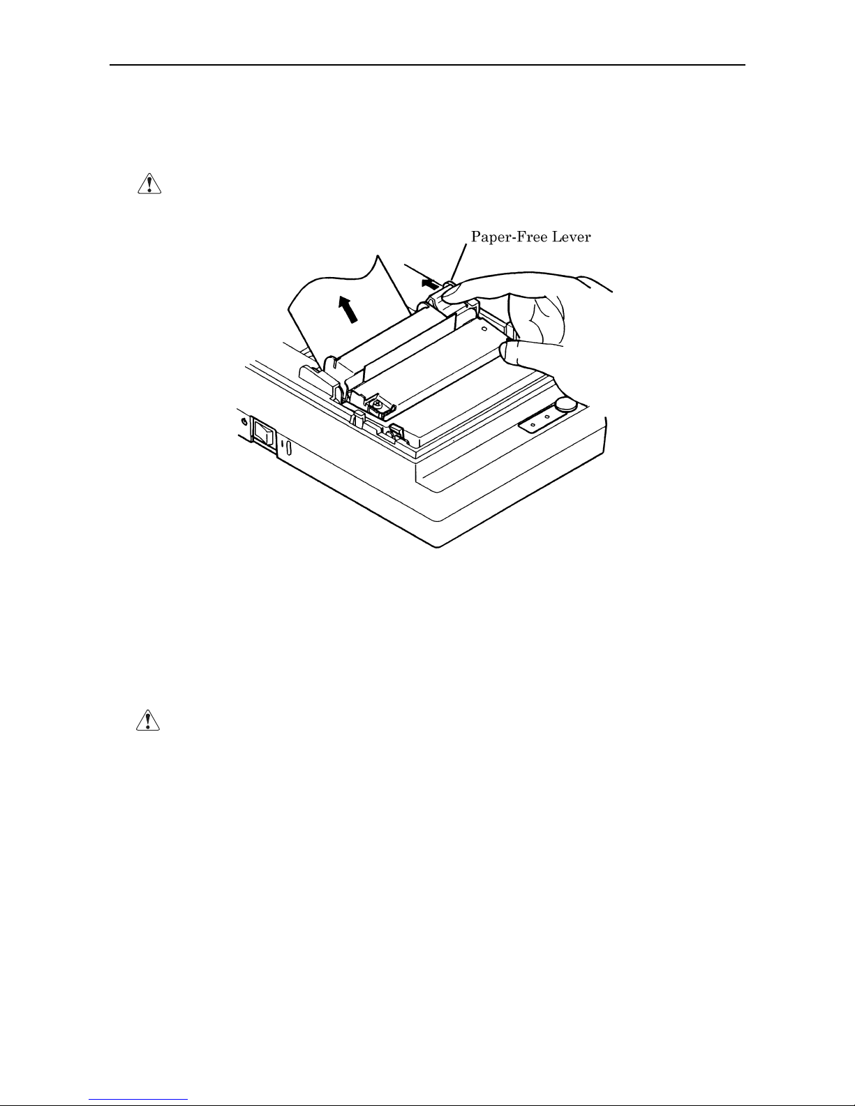
4.6 How to Remove Remaining Paper Roll
(1) Open the printer cover.
(2) Pushing the paper-free lever in the arrow direction, pull out the paper roll.
CAUTION : When pulling out the paper (Forward/Reverse direction), be sure to operate the paper-
free lever.
4.7 Removing Paper Jam
(1) Open the printer cover.
(2) Cut off the paper near the paper inlet slot.
(3) Push the paper-free lever in the arrow direction. The paper feed roller is disengaged, to free the paper,
allowing you to eliminate the jammed paper.
(4) Eliminate completely the paper remaining in the paper route.
CAUTION : • When pulling out the paper (Forward/Reverse direction), be sure to operate the paper-
free lever.
Page 26
iDP3410 User's Manual
12 CITIZEN
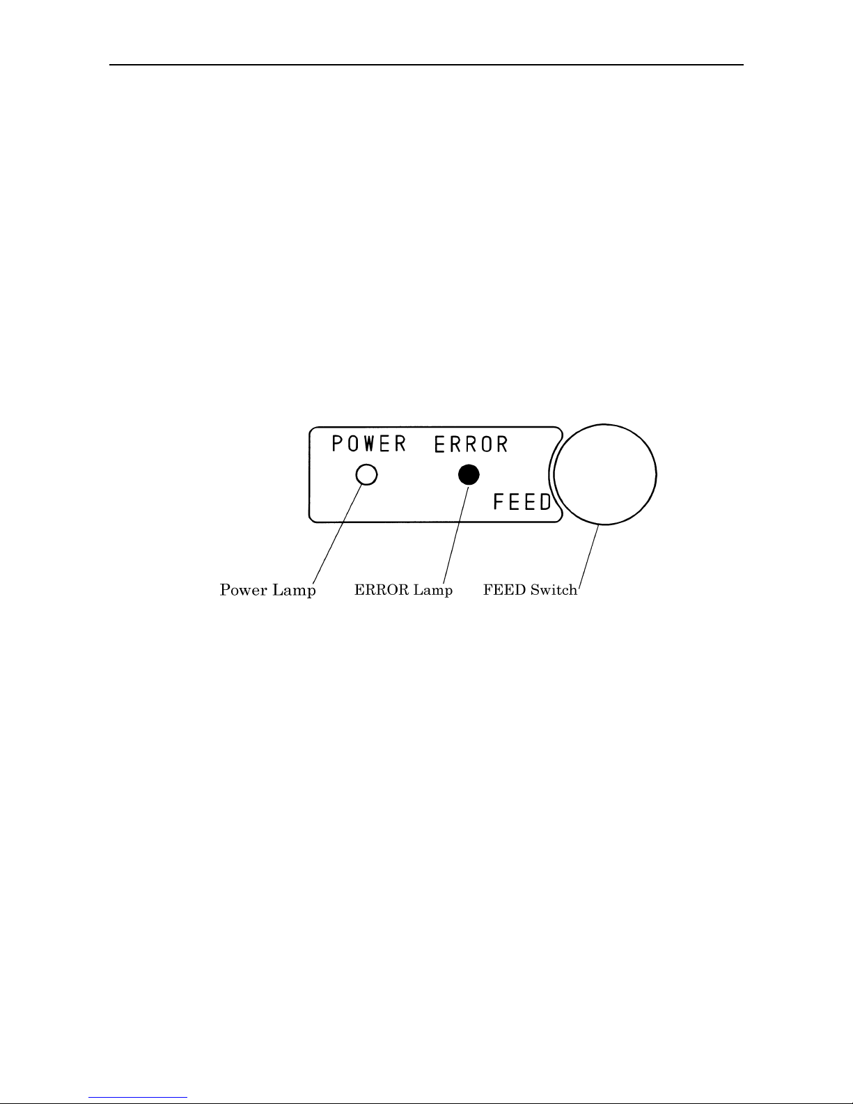
4.8 Operation Panel and Display of Error
(1) POWER lamp(Green)
Illuminated when the power is turned on.
(2) ERROR lamp(Red)
Illuminated when the printer is out of paper or has a printer mechanical error or communication error.
<Details of Errors>
• Paper end ----- If the paper runs out, the paper sensor located in the paper course near the print
head detects a paper end, turning on the ERROR LED, thus stopping the pr inter. If
the paper is inserted into the paper course, it is loaded.
• Printer mechanism error ----- If the printer mechanism is abnormally loaded due to a paper jam,
etc., the ERROR LED is illuminated, to stop the printer.
(3) FEED switch
The paper is fed by one line by pressing this switch for a short time, and it is fed continuously by holding
down the switch.
(4) FEED switch and Power switch
Self-print is performed by turning on the Power switch while pressing the FEED switch.
Page 27
iDP3410 User's Manual
13 CITIZEN
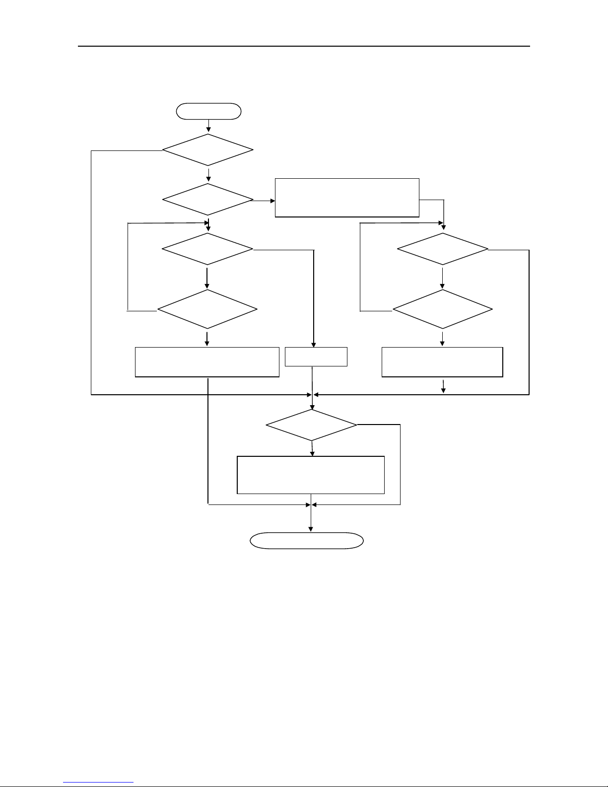
4.9 Operation Flow at Power-on
"Clear Data in Buffer"
Yes(FEED SW) and Enlarged
Red Print
Feed SW ?
Buffer data
FEED SW ?
(CONTINUE)
1 Sec. Passed
Power-on
Yes
No
Prints" =H exade cimalDum p =
Dump Mode
Test Print
No
Yes
Off
On
FEED SW ?
(AGAIN)
1 Sec. Passed
Input Buffer Clear
Yes
No
Off
On
Buffer Data
No
Yes
P
rints "Power Down(Data i
n
B
uffer)" in Red, Followed b
y
B
uffer Contents.
Waits for Data Input
Page 28
iDP3410 User's Manual
14 CITIZEN
5. DIP SWITCH SETTING
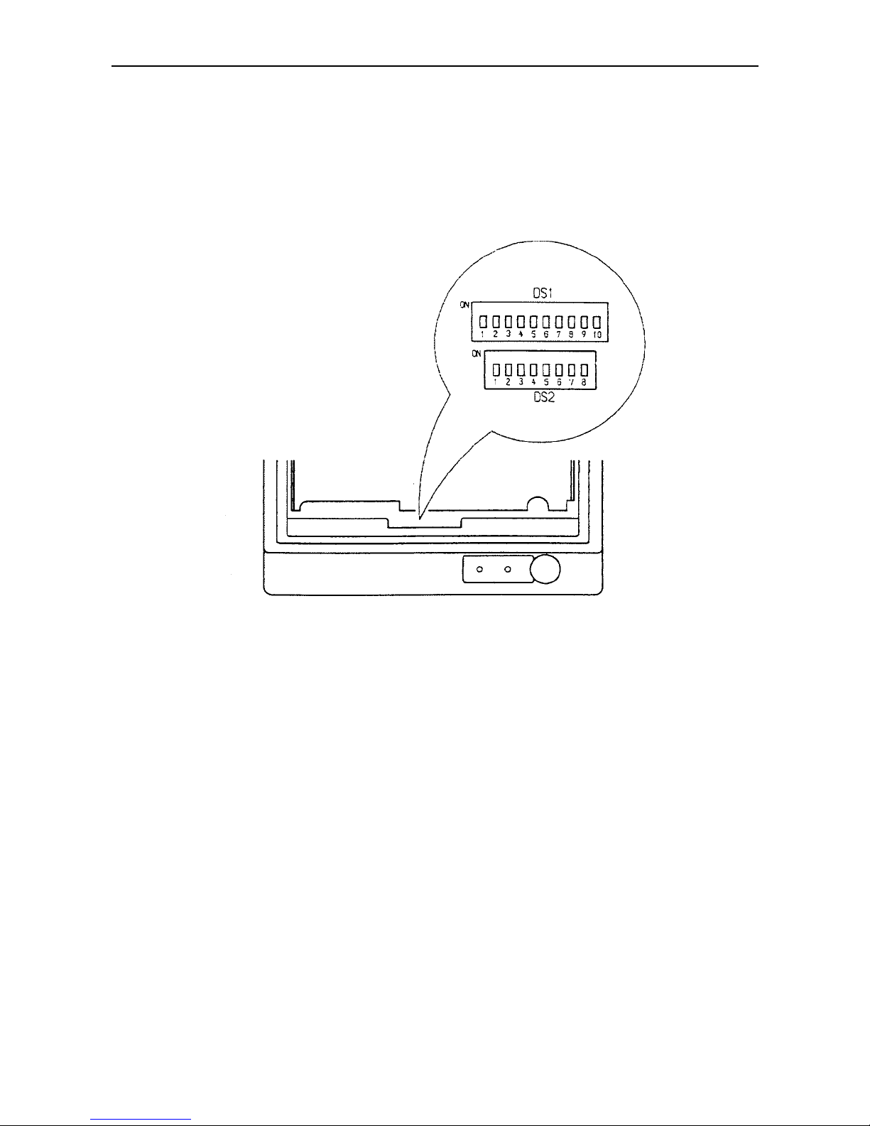
5.1 Location of DIP Switch
(1) Turn off the power.
(2) Remove a cassette ribbon. The DIP switches are located as shown in the figure below.
(Only DS1 provided for the parallel interface)
Page 29

iDP3410 User's Manual
15 CITIZEN
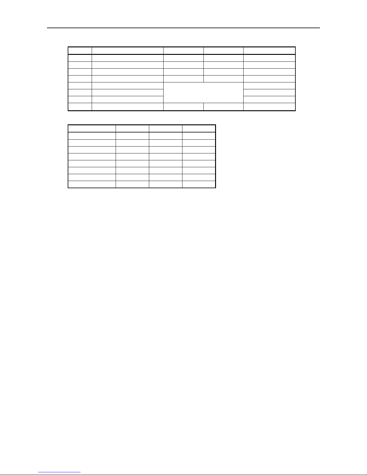
5.2 DIP Switches Setting
1) DIP Switch 1
No. Function ON OFF
Upon Shipment from F acto ry
DS1-1 Auto cutter Yes No OFF
DS1-2
International characters
ON *2
DS1-3
″
ON *2
DS1-4
″
See the Table below
ON *2
DS1-5 Paper used 2P 1P OFF
DS1-6 CR mode See the Table below OFF
DS1-7 Number of columns 42 40 ON
DS1-8 Buffer size 6K bytes 256 bytes ON
DS1-9 Operation mode OFF *3
DS1-10
″
See the table below
OFF *3
*1, *3 : Depends on the type.
*2 : Depends on the destination.
International Character Selection Character Code Selection
No.
ountr
y
DS1-2 DS1-3 DS1-4
ESC/POS
mode
CBM mode Star mode
U.S.A. ON ON ON Code 437
CBM
(International)
Star
(International)
France OFF ON ON Code 850 Code 850 Code 850
Germany ON OFF ON
″″ ″
U.K. OFF OFF ON
″″ ″
Denmark ON ON OFF
″″ ″
Sweden OFF ON OFF
″″ ″
Italy ON OFF OFF
″″ ″
Japan OFF OFF OFF Katakana
CBM
(Domestic)
Star
(Domestic)
See the International Character Codes Table and Character Codes Table.
CR mode(DS1-6) Operation Mode DS1-9 DS1-10
Mode OFF ON CBM OFF OFF
CBM CR+LF CR ESC/POS ON OFF
STAR CR+LF Ignored STAR OFF ON
ESC/POS CR+LF CR STAR ON ON
Page 30
iDP3410 User's Manual
16 CITIZEN
2) DIP Switch 2
No. Function ON OFF Factory Setting
DS2-1 Bit length 8 bits 7 bits ON
DS2-2 Parity No Yes ON
DS2-3 Odd/Even Odd Even ON
DS2-4 Communication mode DTR/DSR XON/XOFF ON
DS2-5 Baud rate ON
DS2-6 ″ ON
DS2-7
″
See the table below
OFF
DS2-8 Unused
−−
OFF
Baud rate
Baud ra te(bps)
DS2-5 DS2-6 DS2-7
150 OFF OFF OFF
300 OFF OFF ON
600 OFF ON OFF
1200 OFF ON ON
2400 ON OFF OFF
4800 ON OFF ON
9600 ON ON OFF
19200 ON ON ON
♦ The DIP switch 2 is used only for the serial interface.
(Note) Setting of the paper used simply changes the drive pulse width to the printing head; it does not
mean that 2 ply paper is not available for the 1 ply setting. The same applies to when 1 ply
paper is used for the 2 ply setting.
Page 31
iDP3410 User's Manual
17 CITIZEN
6. PRESET JUMPER SETTING
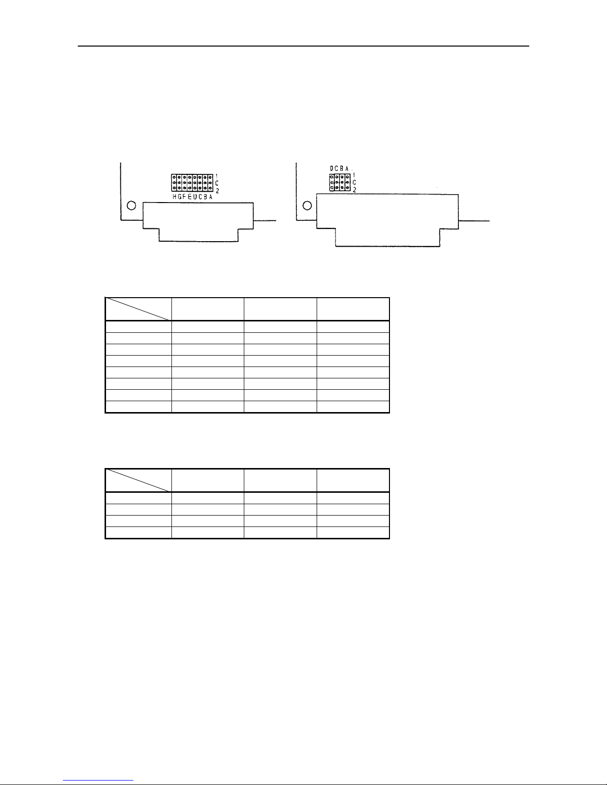
6.1 Location of Preset Jumper
(1) Turn off the power.
(2) Remove a cassette ribbon.
(3) Remove the top cover. The preset jumper is located as shown in the figure below.
Serial Interface Parallel Interface
6.2 Preset Jumper Table
Serial Interface
Mode
Location
CBM STAR ESC/POS
SCA 1-C * 2-C 2-C
SCB 1-C * 1-C * 2-C
SCC 1-C 2-C *
SCD 1-C 2-C *
SCE 1-C * 2-C 1-C *
SCF 1-C * 2-C 1-C *
SCG 1-C * 2-C 1-C *
SCH 1-C 2-C * 2-C *
* = Open
1-C * = 1-C or open
2-C * = 2-C or open
Parallel
Mode
Location
CBM STAR ESC/POS
SCA 1-C * 1-C 2-C *
SCB 1-C 1-C 2-C
SCC 1-C * 1-C * 2-C
SCD 1-C 1-C 2-C *
* = Open
1-C * = 1-C or open
2-C * = 2-C or open
Page 32

iDP3410 User's Manual
18 CITIZEN
7. MODE SETTING METHOD
This printer has the CBM, STAR, and ESC/POS mode. Any desired mode can be selected and set
according to your need.
(1) Setting method
• See 5. DIP SWITCH SETTING.
• Seeing the settings of the DIP switch 1-9 and 1-10 and those of the preset jumper, set each mode.
Page 33

iDP3410 User's Manual
19 CITIZEN
8. INPUT BUFFER BACKUP FUNCTION
8.1 Buffer Size
With the DIP switch, you can set either 6K bytes or 256 bytes.
DIP switch 1-8 ON → 6K bytes
OFF → 256 bytes
8.2 Input Buffer Backup
Even if the power is turned off or fails during the printing process, the data in the input buffer will be saved.
If the power is turned on again, the printer will print a power failure mark, "==POWER DOWN==," in red
and reprints the data from the beginning of the line where it left off.
8.3 Clearing the Input Buffer
When you want to clear the data in the input buffer, turn on the power, holding down the LF switch. A
buzzer will sound to inform you that the input buffer has been cleared. Hold down the LF switch until the
buzzer sounds.
If the printer prints the data erroneously at power-on, clear the input buffer as described above, and then, reinput the data.
Page 34
iDP3410 User's Manual
20 CITIZEN
9. PARALLEL INTERFACE
9.1 Specifications
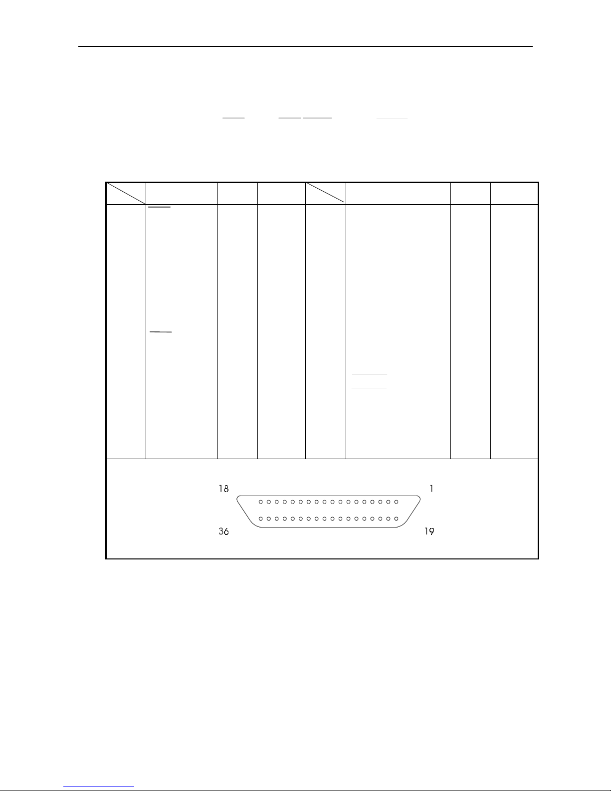
• Data input system : 8-bit parallel system (DATA1 to DATA8)
• Control signals : ACK, BUSY, STB, FAULT, SELECT, RESET, COMPULSION
• Applicable connectors : Printer side --- 57LE-40360 (Equivalent to anphenol),
Cable side --- 57-30360 (Ditto)
9.2 Connector's Pin Configuration
Mode
No.
CBM STAR ESC/POS
Mode
No.
CBM STAR ESC/POS
1
2
3
4
5
6
7
8
9
10
11
12
13
14
15
16
17
18
STB
DATA 1
DATA 2
DATA 3
DATA 4
DATA 5
DATA 6
DATA 7
DATA 8
ACK
BUSY
PE(HI-LEVEL)
SELECT
GND
GND
GND
FRAME GND
Vcc
←
←
←
←
←
←
←
←
←
←
←
←
←
←
NC
NC
←
←
←
←
←
←
←
←
←
←
←
←
←
←
←
←
←
←
←
NC
19
20
21
22
23
24
25
26
27
28
29
30
31
32
33
34
35
36
TWISTED PAIR GND
↑
↑
↑
↑
↑
↑
↑
↑
↑
↑
↑
RESET
FAULT
NC
COMPULSION
NC
Vcc
←
←
←
←
←
←
←
←
←
←
←
←
←
←
←
←
←
←
←
←
←
←
←
←
←
←
←
←
←
←
←
GND
←
←
Vcc
NC
Page 35

iDP3410 User's Manual
21 CITIZEN
9.3 Input and Output Signals
9.3.1 Input and Output Signals
(1) Input signals to the printer
• DATA : An 8-bit parallel signal. (Positive logic)
• STB : A strobe signal to read the 8-bit data. (Negative logic)
• RESET : A signal to reset the printer from the outside.(Negative logic)
(2) Output signals from the printer
• ACK : An 8-bit data request signal. A pulse signal output at the end of the BUSY signal.
(Negative logic)
• BUSY : A signal to indicate the BUSY status of the printer. Input new data when at
"LOW". (Positive logic)
• FAULT : A signal turned to "LOW" when the printer has an alarm. At this time, all the
control circuits in the printer stop. (Negative logic)
• SELECT : A signal to show whether the printer is selected(on-line) or deselected.(Positive
logic)
• COMPULSION
: A signal to show the status of the drawer switch.(Positive logic)
• PE : A signal to show that the paper has run out. Normal at the "LOW" level, but turned
to the "HIGH" level when the paper has run out.
(3) Power related signal
• GND : Common ground on the circuits
• Vcc : A +5V signal. Connected via a 3.3kΩ resistor.
Page 36
iDP3410 User's Manual
22 CITIZEN
9.3.2 Electrical Characteristics
(1) Input signal level
All the input signals are at the TTL level.
"HIGH" level : 2.0 V at minimum
"LOW" level : 0.8 V at maximum
(2) Output signal level
All the output signals are at the TTL level.
"HIGH" level : 2.4 V at minimum
"LOW" level : 0.4 V at maximum
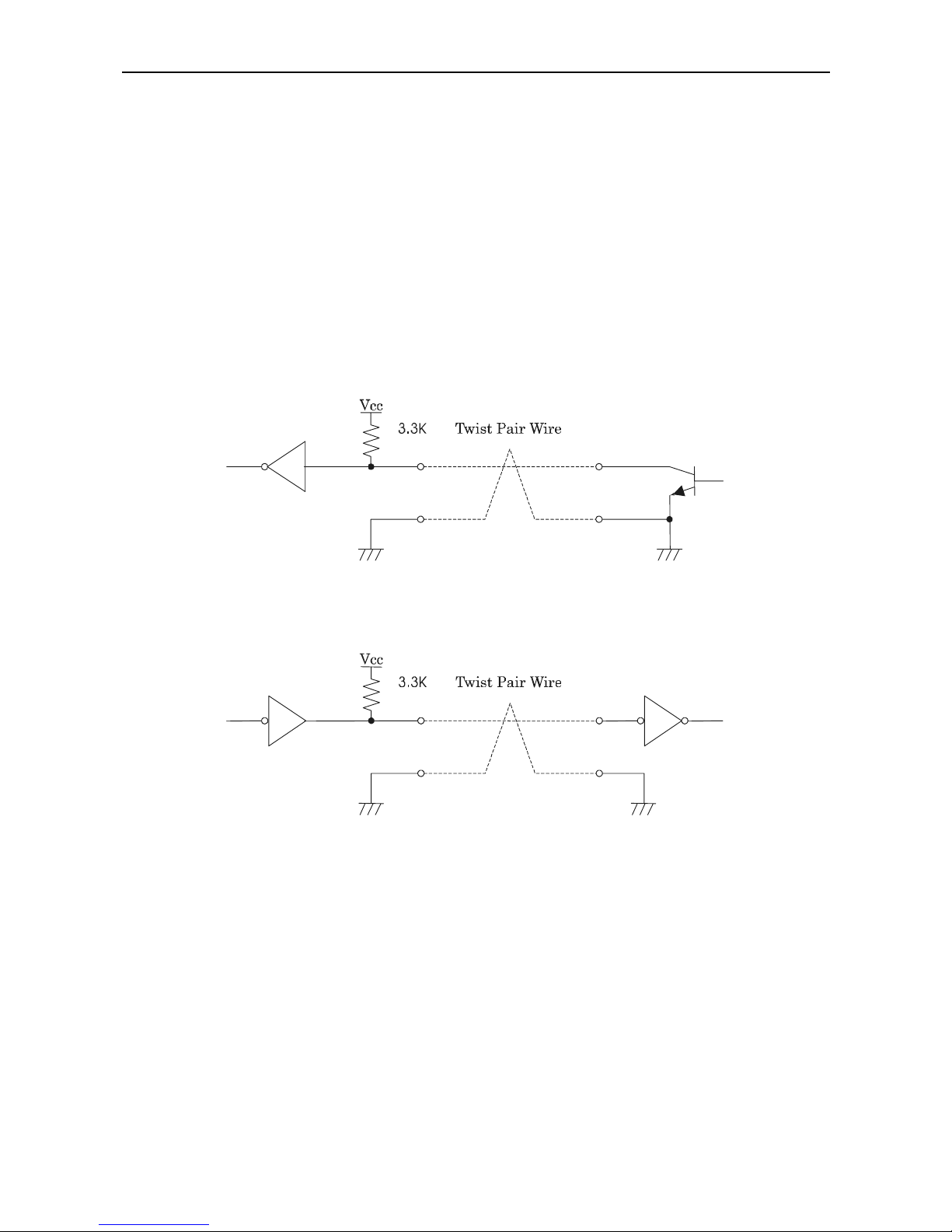
(3) Input and output conditions
All the input signals are pulled up at 3.3 kΩ.
[Printer Side] [Host Side]
All the output signals are pulled up at 3.3kΩ.
[Printer Side] [Host Side]
Page 37
iDP3410 User's Manual
23 CITIZEN
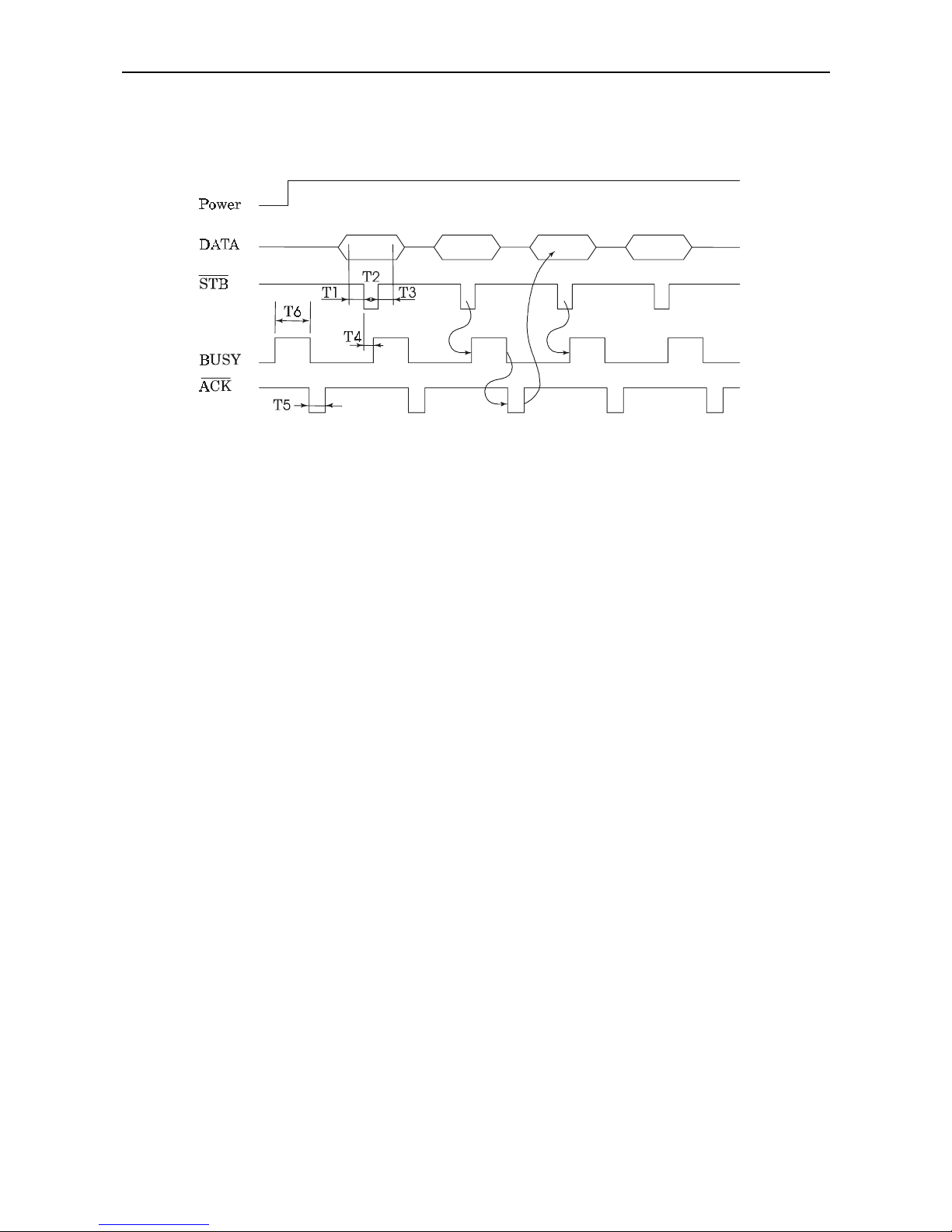
9.3.3 Timing Chart
(1) Data input and printing timing
T1, T2, T3 : 0.5 µs MIN
T4 : 270 ns MAX
T5 : 2.3 µs TYP
T6 : 500 ms MIN (At power-on)
9.3.4 Data Receiving Control
When the BUSY signal is at "LOW," the printer can receive the data from the host, but when at "HIGH,"
it cannot.
Page 38

iDP3410 User's Manual
24 CITIZEN
10. SERIAL INTERFACE
10.1 Specifications
(1) Synchronous system: Asynchronous
(2) Baud rate: 150, 300, 600, 1,200, 2,400, 4,800, 9,600, or 19,200 bps (User selectable)
(3) Configuration of one word
• Start bit : 1 bit
• Data bits : 7 or 8 bits (User selectable)
• Parity bit : Odd, even, or none (User selectable)
• Stop bit : 1 bit or more
(4) Signal polarity
RS-232C
• Mark = Logic "1" (-3 V ∼ -12 V)
• Space = Logic "0" (+3 V ∼ +12 V)
(5) Received data (RXD signal)
RS-232C
• Mark = 1
• Space = 0
(6) Reception control (DTR signal)
RS-232C
• Mark : Data transfer disabled
• Space : Data transfer enabled
Page 39
iDP3410 User's Manual
25 CITIZEN
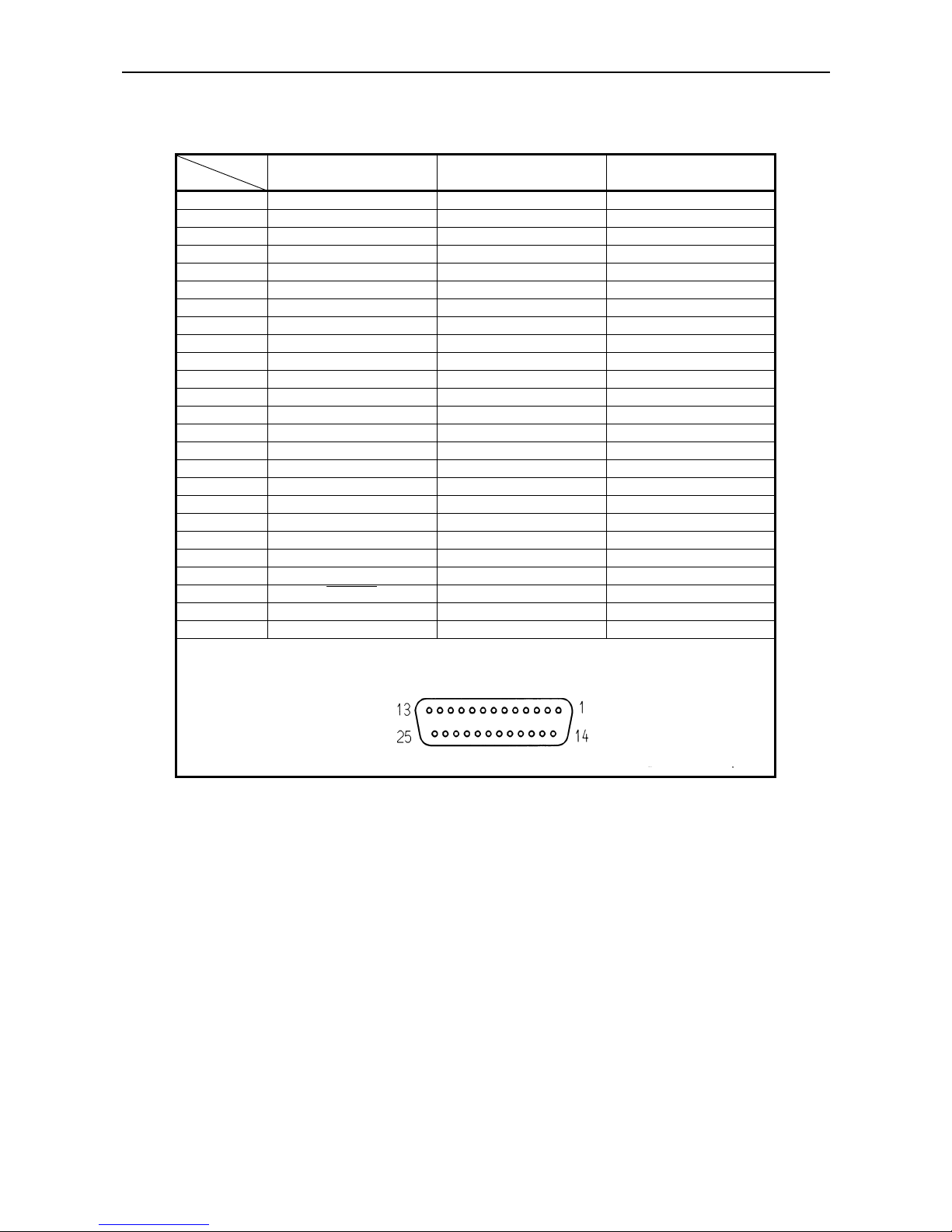
10.2 Connector's Pin Configuratio n
Mode
No.
CBM STAR ECS/POS
1FG
←←
2TXD
←←
3RXD
←←
4RTS
←
5
6DSR
7 GND ←←
8
9
10
11 PE (HI-LEVEL) RCH
12 FAULT
13 GND
14 FAULT
15 mTXD
16 mRXD
17
18
19
20 DTR
←←
21
22
23 RESET
24
25
Cautions
: 1. An RS-232C signal is based on the EIA RS-232C.
2. When the data is not being transferred, the received data should be always maintained
as a mark.
Page 40

iDP3410 User's Manual
26 CITIZEN
10.3 Input and Output Signals
10.3.1 Input and Output Signals
(1) RXD
This is a serial received data signal. When a framing error, overrun error, or parity error occurs, that
data is printed as "?".
(2) DTR
When this signal is Ready, write the data or a command. If written at the time of Busy, an overrun
error results, ignoring the previous data. The da ta can be written in the input buffer even during
printing. Busy is also issued at the time of power-on, test print, on-line, and reset.
(3) TXD
XON(11H) or XOFF(13H) is sent at XON/XOFF control. XON(11H) is sent every 3 seconds in the
Star mode.
When a command is received, that requests the printer state and printer status, 1-byte corresponding
data is output.
(4) DSR
When this signal is a space, the data is sent from the printer side . Note that if this signal is a mark
when a request to send command is executed, the printer will wait until the signal becomes a space.
(5) FAULT
1) CBM mode
When this signal is Space, a mechanical error has occurred.
2) STAR mode
When this signal is Mark, a mechanical error has occurred.
(6) RESET
A signal to reset the entire printer.(Negative logic)
(7) RTS
This signal is turned to Space when the printer is turned on.
Page 41

iDP3410 User's Manual
27 CITIZEN
(8) RCH
When the printer is ready to receive, this signal is turned to Space. This signal line is the same as
DTR.
(9) mTXD
TXD signal for the diode gate.
(10) mRXD
RXD signal for the diode gate.
(11) FG
This is a Frame Ground signal.
(12) GND
This is a common ground on the circuit.
Page 42
iDP3410 User's Manual
28 CITIZEN
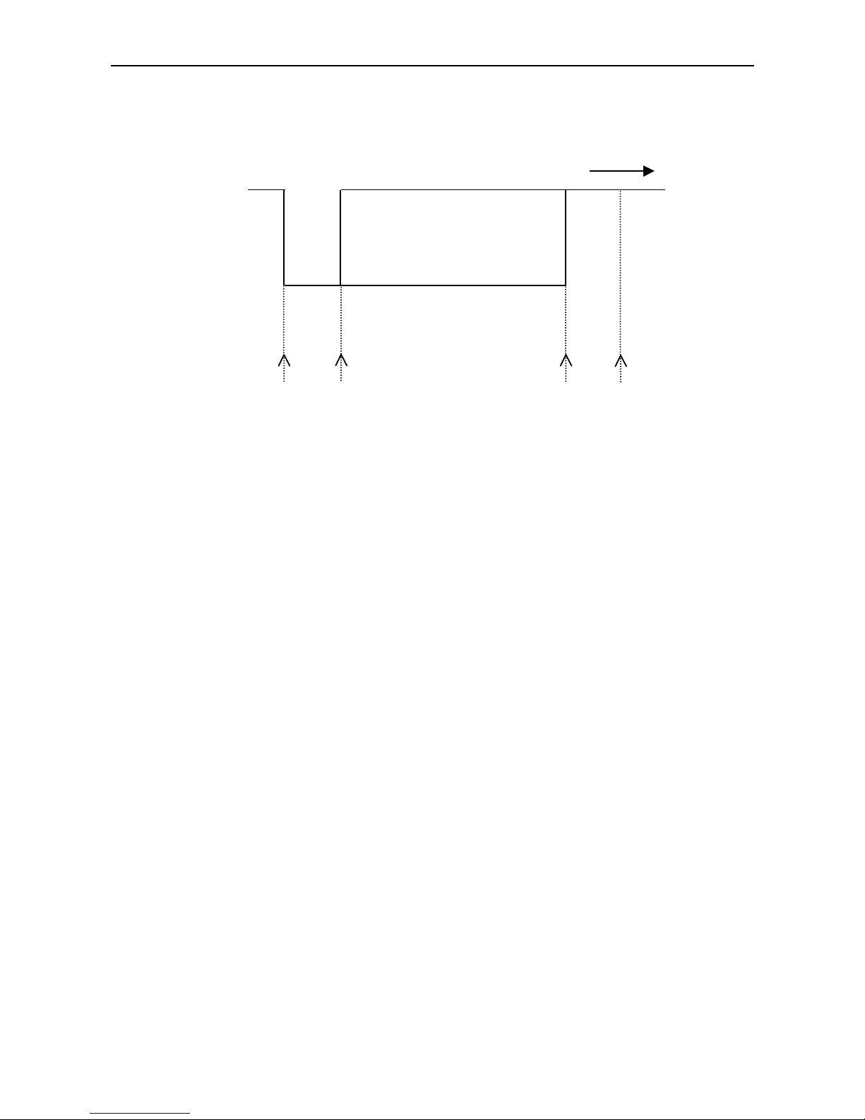
10.3.2 Data Configuration
t
Mark
b
0
, b1, b2, ........
Space (1) (2) (3)
(1) Start Bit
(2) Data Bit (+ Parity Bit)
(3) Stop Bit (1 or More)
(1) Start bit
After a lapse of 1/2 bit from a mark-to-space fall edge, the state is read again, and if it is a space, it is
recognized as the start bit. If it is a mark, it is assumed neither the start bit nor an error, and it is
attempted to detect the start bit again.
(2) Data bit + parity bit
The data bit and parity bit are sampled for 1 bit worth of time from the 1/2 start bit. The then state is
assumed the data for the corresponding bit. A sequence of the bits are named Bit 0, Bit 1, ..., parity
bit, starting from the one closest to the start bit.
(3) Stop bit
The stop bit is a mark level of 1 bit or more. If a space is detected in detecting the stop bit, a framing
error resul ts .
Page 43

iDP3410 User's Manual
29 CITIZEN
10.3.3 Error Detection
A parity error, framing error, and overrun error are detected. When an error is detected, that data is
stored in the buffer as "?".
(1) Framing error
This error results when a space is detected in detecting the stop bit. That da ta is stored in the buffer
as "?".
(2) Parity error
If a parity check has been specified and an error is detected at the time of parity check, that data is
stored in the buffer as "?".
(3) Overrun er ror
If an overrun error is detected, that data is stored in the buffer as "?".
10.3.4 Data Receiving Control
When the DTR signal is a space, the data from the host side can be received. When it is a mark,
however, the data cannot be received.
10.3.5 Buffering
The DTR signal and the TXD signal are available as a control signal for data transfer to the input buffer.
Page 44
iDP3410 User's Manual
30 CITIZEN
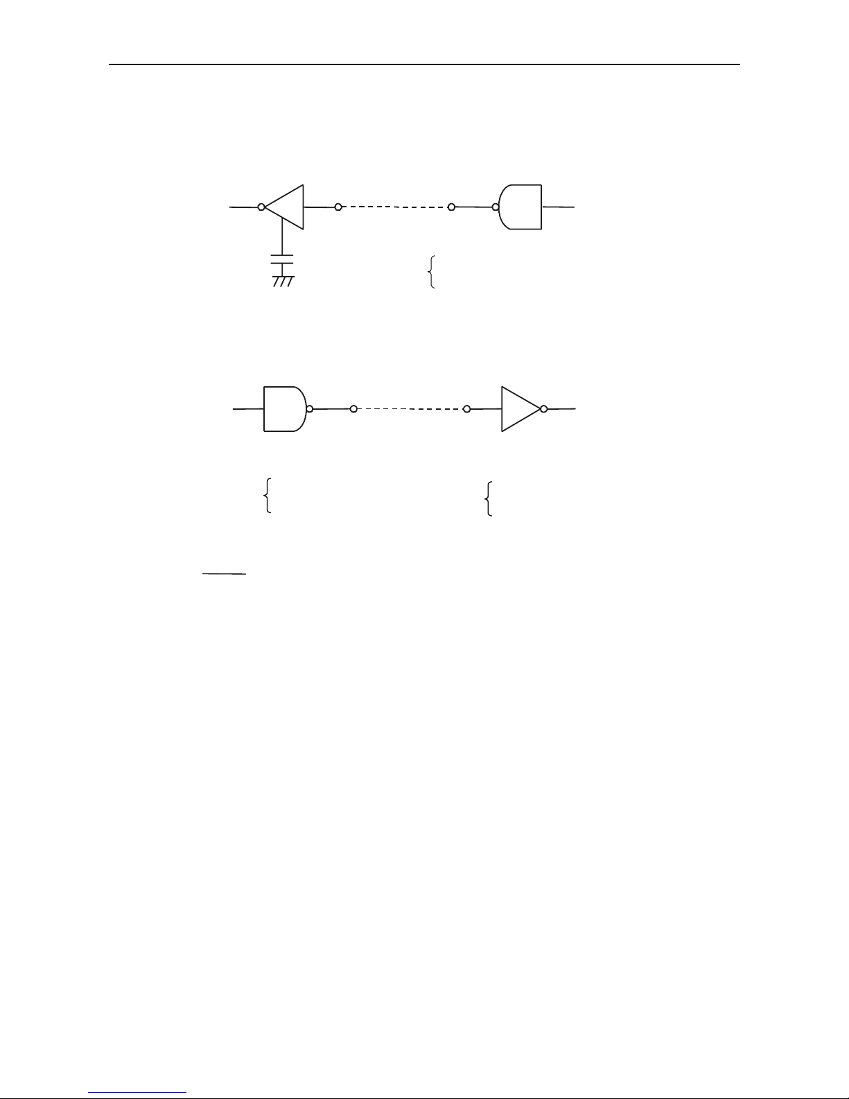
10.3.6 Electrical Characteristics
(1) RS-232C circuit
Input (RXD, DSR, mRXD)
[Printer Side] [Host Side]
Output (DTR, TXD, mTXD, RCH, RTS, FAULT)
Equival ent to MAX232
DTR Mark=(-8V): At Busy TXD Mark=(-8V): 1
Space=(+8V): At Ready Space=(+8V): 0
(2) Others
• RESET : A signal to reset the entire printer.
• PE : A signal to show that the paper has run out. Normal at the "LOW" level, but turned
to the "HIGH" level when the paper has run out.
• GND : Signal ground
• FG : Frame ground
Equivalent MAX232
RXD Mark=(-8V): Stop bit
Space=(+8V): Start bit
Page 45
iDP3410 User's Manual
31 CITIZEN
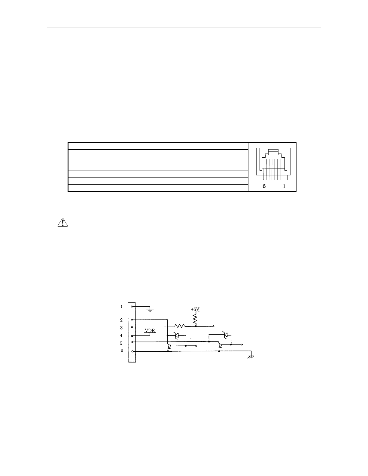
11. DRAWER KICK-OUT CONNECTOR AND POWER CONNECTOR
11.1 Specifications of Drawer Kick-Out Connector
(1) Drawer kick-out drive signal
Parallel Interface ----- Can be learned at the no. 34 pin of the interface connector
Serial Interface ----- Provided with a command to learn the status in the Star and ESC/POS modes.
(2) Electrical characteristics
1) Drive voltage: 24 V DC
2) Drive current: 0.8 A at maximum(Within 510 ms)
3) Switch signal: Signal level "L" = 0 ∼ 0.5 V
"H" = 3 ∼ 5 V
11.2 Connector's Pin Configuratio n
No. Signal Function
1 FG Frame Ground
2 DRAWER 1 Drawer 1 drive signal
3 DRSW Drawer switch input
4 VDR Drawer drive power
5 DRAWER 2 Drawer 2 drive signal
6 GND Common ground on the circuit
Connector used : TM5RJ3-66 (HIROSE)
Applicable connector : TM3P-66P (HIROSE) or equivalent
CAUTION
: • No output is made while printing.
• The drawers 1 and 2 cannot be driven simultaneously.
• A solenoid used for the drawer should be of 36Ω or more. An output current should be
kept below 0.8 A. Use beyond this limit cannot be assured.
• This connector cannot be connected to a telephone line. Do not connect other than the
solenoid.
11.3 Drive Circuit
Page 46
iDP3410 User's Manual
32 CITIZEN
11.4 Specifications of Power Supply Connector
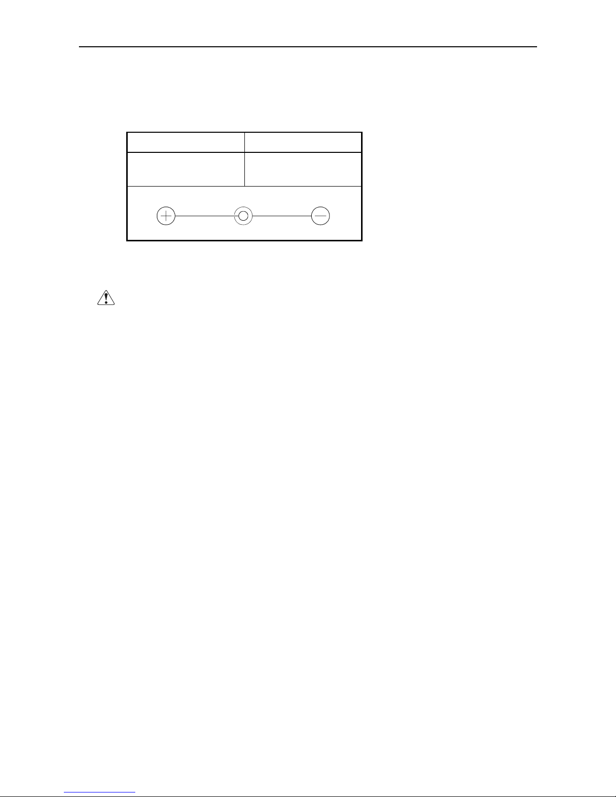
This is a power connector from an exclusive AC adapter.
Connector’s Pi n Configuration
No. Function
1
2
+24V
GND
12
Jack used : HEC0470-01-640(HOSHIDEN) or equivalent
Applicable plug : JXP series Type-A (I.D. 2.45 mm, O.D. 5.5 mm) (HOSHIDEN) or equivalent
CAUTION: • Be sure to use the specified power supply. Use of unspecified one may lead to a
trouble or breakage.
• Do not connect the power supply with different polarities.
Page 47

iDP3410 User's Manual
33 CITIZEN
12. MAINTENANCE AND SERVICE
For the information on maintenance and service, please contact our dealer or at the following address.
Northern Americ a Other Areas
CBM America Corporation Japan CBM Corporation
Service Center Information Systems Division
365 Van Ness Way CBM Bldg., 5-68-10, Nakano
Suit 510 Nakano-ku, Tokyo 164-0001
T orr ance, CA 90501, U.S.A Japan
TEL +1-310-781-1460 TEL +81-3-5345-7540
FAX +1-310-781-9157 FAX +81-3-5345-7541
Page 48
iDP3410 User's Manual
34 CITIZEN
13. PRINT CONTROL FUNCTIONS
13.1 CBM Mode
13.1.1 Command List
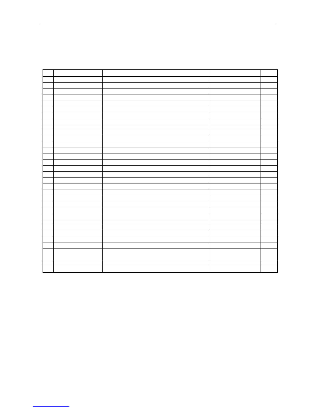
Command Function Code Page
1 FF n n-line paper feed 0CH n 36
2 SO Specifying the double width character 0EH 36
3 SI Canceling the double width character 0FH 37
4 LF Printing and paper feed 0AH 37
5 CR Printing 0DH 37
6 DC 1 Initializing the printer 11H 37
7 DC 2 Specifying/Canceling the Inverted character 12H 37
8 DC 3 Specifying the red print 13H 38
9 CAN Canceling the print data 18H 38
10 ESC ∗ n1 n2 Specifying the bit image mode 1BH 2AH n1 n2 39
11 ESC - n Specifying/Canceling the Underline 1BH 2DH n 39
12 ESC 1 Specifying 1/9-inch line feed rate 1BH 31H 39
13 ESC 2 Specifying 2/9-inch line feed rate 1BH 32H 40
14 ESC 3 Specifying 1/6-inch line feed rate 1BH 33H 40
15 ESC C n Setting the page length 1BH 43H n 40
16 ESC N n Specifying the perforation skip 1BH 4EH n 41
17 ESC O Canceling the perforation skip 1BH 4FH 41
18 ESC f 1 Form feed (Changing the page) 1BH 66H 01H 41
19 ESC t n Selecting the character code table 1BH 74H n 42
20 ESC BEL n1 n2 Setting the external device drive pulse width 1BH 07H n1 n2 43
21 BEL Driving command A for Drawer-1 07H 43
22 FS Driving command B for Drawer-1 1CH 44
23 SUB Driving command for Drawer-2 1AH 44
24 RS Buzzer-on 1EH 44
25 ESC R n Selecting the international character set 1BH 52Hn 45
26 ESC & 0 n1 n2 Defining the download character set 1BH 26H 00H n1 n2 46
27 ESC % n Specifying/Canceling download character set 1BH 25H n 39
28 ESC / n Definition the message 1BH 2FH n 39
29 ESC DC3 n Printing the message 1BH 13H n 48
30 ESC DC2 n1 n2
Deleting the download character, message, bit
image
1BH 12H n1 n2 49
31 GS ∗ n1 n2 Defining the download, bit image 1DH 2AH n1 n2 50
32 GS / m Printing the download, bit image 1DH 2FH m 51
Page 49

iDP3410 User's Manual
35 CITIZEN
13.1.2 Description of Items
XXXX
ALL
[Function] Command name
[Code] A row of command constituent code is represented by a hexadecimal number with < >H,
binary number with < >B, and a decimal number with < >. [ ]k means a repeat count of ktimes.
[Range] Describes an argument value (Setting range) for the command.
[Outline] Describes a command function.
[Caution] Describes a caution as required.
[Default] Describes an initial value for the command when accompanied by an argument.
XXX Shows a command.
Page 50

iDP3410 User's Manual
36 CITIZEN
Details
FF n
[Function] n-line paper feed
[Code] <0C>H n
[Range] 1 ≤ n ≤ 127
[Outline] This command feeds the paper by n-lines. You can set n = 1 to 127 lines. If the print
buffer contains the data, use of this command feeds the paper by n-lines after printing the
data. Setting n = 0 does not feed the paper.
SO
[Function] Specifying the double width character
[Code] <0E>H
[Outline] The data following this command is printed doubled in the horizontal direction. Double
width characters remain valid until the double width character cancel command is entered,
but they are also cancelled after they are printed one line. Note that the double width
characters take up two ordinary characters worth of width.
Page 51

iDP3410 User's Manual
37 CITIZEN
SI
[Function] Canceling the double width character
[Code] <0F>H
[Outline] This command cancels the double width characters set with SO. The data following this
command are printed in the ordinary character width.
LF
[Function] Printing and paper feed
[Code] <0A>H
[Outline] If the print buffer contains the data, this command will feed the line after printing. If not,
the command only feeds the line.
CR
[Function] Printing
[Code] <0D>H
[Outline] This command prints the data. If the DIP switch segments 1 to 6 are set to OFF, the
printer will print the data in the print buffer and feed the paper by one line. If they are set
to ON, the printer will print the data in the print buffer and will not feed the paper.
DC1
[Function] Initializing the printer
[Code] <11>H
[Outline] This command initializes the printer.
The input buffer is not cleared.
The settings of the DIP switch segments are not re-read.
DC2
[Function] Specifying/Canceling the inverted character
[Code] <12>H
[Outline] This command selects/deselects the inverted characters. Enter this command at the
beginning of one line. Otherwise, it is overridden. Erect and inverted characters cannot be
mixed in one line.
Page 52

iDP3410 User's Manual
38 CITIZEN
DC3
[Function] Specifying the red print
[Code] <13>H
[Outline] This command specifies red-color characters. All the characters in one line are printed in
red by prefixing the print data with this command and sending it to the printer. When you
want to use red characters, use this command for each line.
CAN
[Function] Canceling the print data
[Code] <18>H
[Outline] This command clears the print data in the lines entered prior to this command.
Page 53
iDP3410 User's Manual
39 CITIZEN
ESC "*" n1 n2
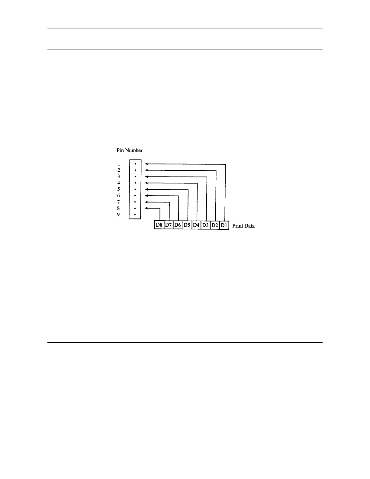
[Function] Specifying the bit image mode
[Code] <1B>H <2A>H n1 n2
[Range] 1 ≤ n1 + 256 × n2 ≤ 378
[Outline] This command allows printing in the bit image mode. Divide the number of dots printed
by 256 and assume its quotient to be n2 and remainder to be n1. Therefore, the number of
horizontal dots will be n1 + 256 × n2.
If the bit image data is entered beyond the dot positions printable in one line, the surplus
data will be discarded. Normal data processing is restored after bit image printing.
Printing is done in a single direction.
ESC "-" n
[Function] Specifying/Canceling the underline
[Code] <1B>H <2D>H n
[Outline] This command selects/deselects an underline. The underline is selected at n = 1 and
deselected at n = 0.
[Default] n = 0
ESC "1"
[Function] Setting the 1/9-inch line feed width
[Code] <1B>H <31>H
[Outline] This command sets the line feed width to 1/9 inch.
Page 54

iDP3410 User's Manual
40 CITIZEN
ESC "2"
[Function] Setting the 2/9-inch line feed width
[Code] <1B>H <32>H
[Outline] This command sets the line feed width to 2/9 inch.
ESC "3"
[Function] Setting the 1/6-inch line feed width
[Code] <1B>H <33>H
[Outline] This command sets the line feed width to 1/6 inch(Default).
ESC "C" n
[Function] Setting the page length
[Code] <1B>H <43>H n
[Range] 1 ≤ n ≤ 127
[Outline] Sets the 1-page length to n-lines.
Page 55

iDP3410 User's Manual
41 CITIZEN
ESC "N" n
[Function] Specifying the perforation skip
[Code] <1B>H <4E>H n
[Range] 1 ≤ n ≤ 126
[Outline] This command feeds(Skips) the lines specified with n without printing. However, you
cannot specify beyond the length of one page.
ESC "O"
[Function] Canceling the perforation skip
[Code] <1B>H <4F>H
[Outline] This command cancels perforation skipping operation.
ESC "f" 1
[Function] Form feed (Changing the page)
[Code] <1B>H <66>H <01>H
[Outline] This command searches for the beginning of the next page after pr inting the data in the
print buffer.
Page 56
iDP3410 User's Manual
42 CITIZEN
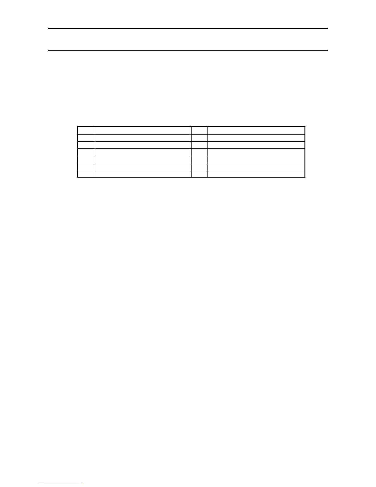
ESC "t" n
[Function] Selecting the character code table
[Code] <1B>H <74>H n
[Range] 0 ≤ n ≤ 255
[Outline] This command selects Page-n of Character Code Table.
[Default] Depends upon DIP switch setting.
n Character Code Table n Character Code Table
0 CBM International 6 Code Page 852 (Eastern Europe)
1 CBM Domestic 7 Code Page 866 (Russia)
2 Code Page 850 (Multilingual) 8 Code Page 857 (Turkey)
3 Code Page 860 (Portugal) 9 Windows Code
4 Code Page 863 (Canada-French)
5 Code Page 865 (Norway) 255 Space Page (For user setting)
Page 57
iDP3410 User's Manual
43 CITIZEN
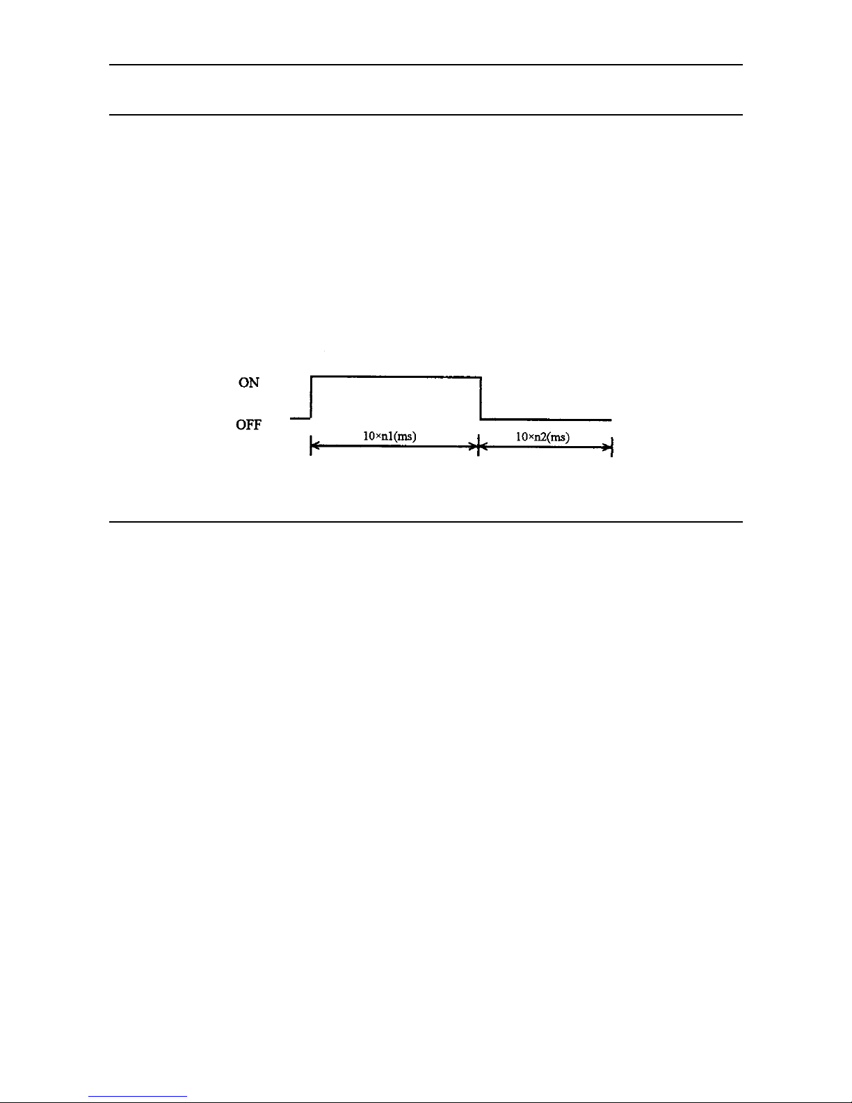
ESC BEL n1 n2
[Function] Setting the external device drive pulse width
[Code] <1B>H <07>H n1 n2
[Range] 1 ≤ n1 ≤ 127 1 ≤ n2 ≤ 127
[Outline] This command sets the power-on time to drive an external device (Cash drawer).
Power-on time = n1 × 10 (ms)
Delay time = n2 × 10 (ms)
To actually drive the drawer, use the <BEL> and <FS> commands.
[Default] n1 = n2 = 20
BEL
[Function] Driving command A for drawer-1
[Code] <07>H
[Outline] This command drives the drawer connector no. 2 pin under the condition set with the
<ESC><BEL> n1 n2 command. This command is executed in order of entry into the
input buffer.
Page 58

iDP3410 User's Manual
44 CITIZEN
FS
[Function] Driving command B drawer-1
[Code] <1C>H
[Outline] This command drives the drawer connector No. 2 pin under the condition set with the
<ESC><BEL> n1 n2 command.
SUB
[Function] Driving command for drawer-2
[Code] <1A>H
[Outline] As soon as this command is received, the drawer connector no. 5 pin is driven. The
power-on time is 200 ms O N and 200 ms OFF stationary. The drawers 1 and 2 cannot be
driven simultaneously.
RS
[Function] Buzzer-on
[Code] <1E>H
[Outline] This command emits a short warning sound from the printer.
Page 59
iDP3410 User's Manual
45 CITIZEN
ESC "R" n
[Function] Selecting the international character set
[Code] <1B>H <52>H n
[Range] 0 ≤ n ≤ 10
[Outline] This command selects the international characters according to the value of n.
n Character Set n Character Set
0 U.S.A. 6 Italy
1 France 7 Spain
2 Germany 8 Japan
3U.K.9Norway
4 Denmark I 10 Denmark II
5 Sweden
[Default] Depends upon DIP switch setting.
Page 60
iDP3410 User's Manual
46 CITIZEN
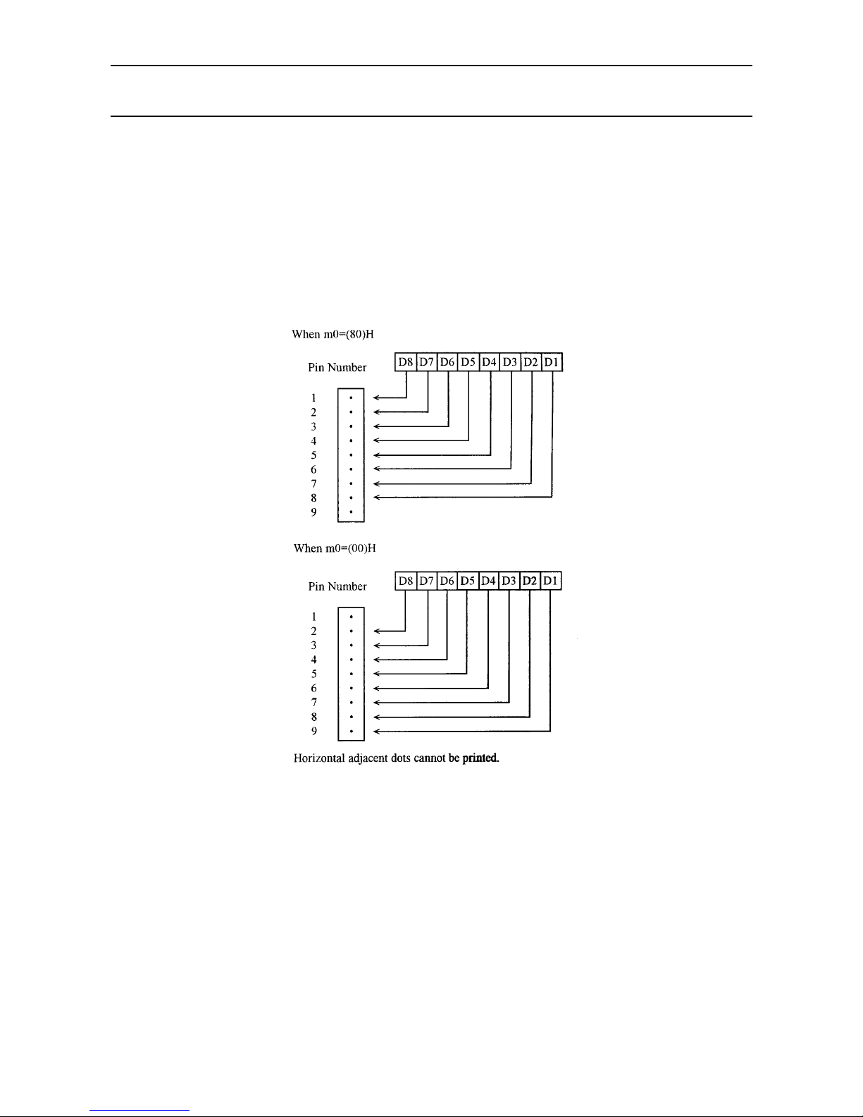
ESC "&" <0> n1 n2 [m0 m1 ... m5 m6 m7 m8 m9] n2 - n1 + 1
[Function] Defining the Download character set
[Code] <1B>H <26>H <00>H n1 n2 [m0 m1 ... m5 m6 m7 m8 m9] n2 - n1 + 1
[Range] 32 ≤ n1 ≤ n2 ≤ 255 m0 = 0 or m0 = 128
[Outline] This command defines he download characters. n1 is a character c ode to start definition
and n2 is to end definition, respectively. When defining only one character, set n1 = n2.
You can define the ASCII codes ranging from 32 to 255. Once the download characters
are defined, they remain valid until they are redefined or the download deletion command
(ESC DC2 n1 n2) is executed.
Page 61
iDP3410 User's Manual
47 CITIZEN
ESC "%" n
[Function] Specifying/Canceling the download character set
[Code] <IB>H <25>H n
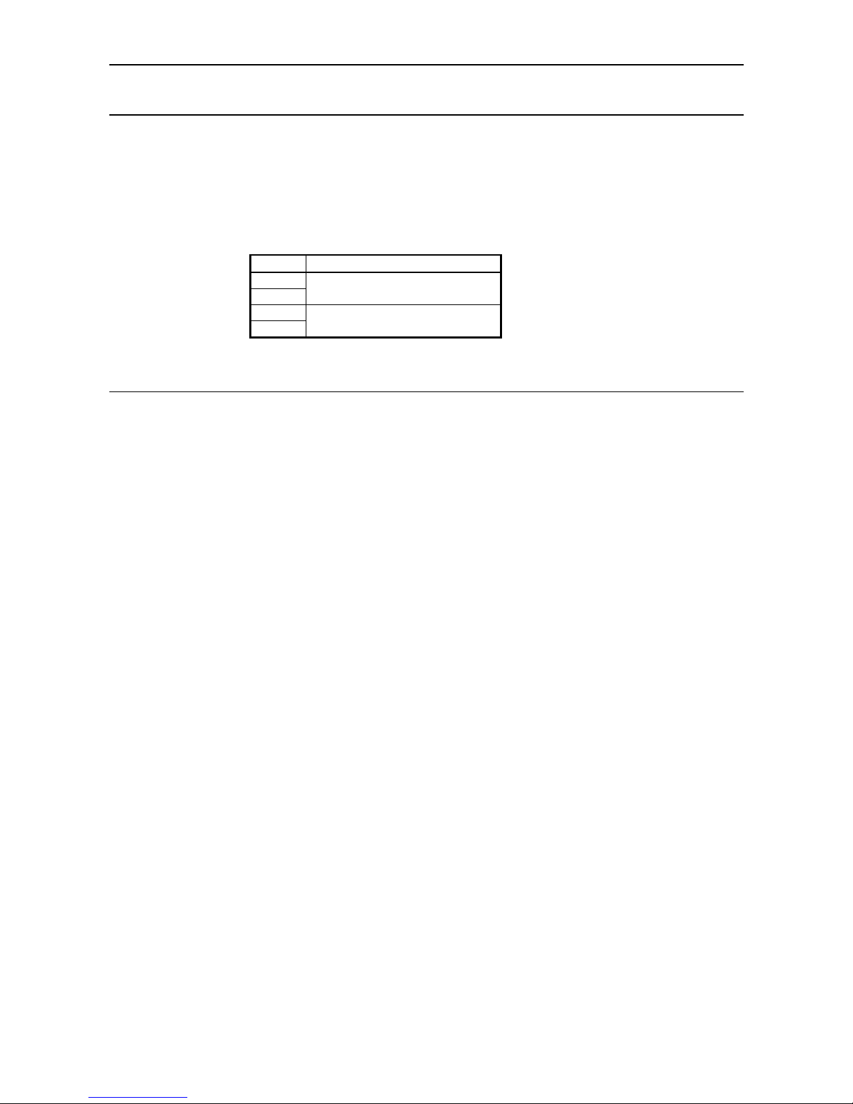
[Outline] This command selects/deselects the download character set. The download characters
cannot be printed by simply defining them with the above-mentioned ESC & 0 command.
To print them, send this command to the printer.
n Download Character Set
0
30
Deselects
1
31
Selects
ESC "/" n "data" CR or LF
[Function] Defining the Message
[Code] <1B>H <2F>H n "data" CR or LF
[Range] 1 ≤ n ≤ 10
[Outline] This command can define up to a 50-byte message in one line. If the value of n is
specified beyond the range, the data following n will be treated as the print data.
Once the message is defined, it remains valid until it is redefined. The data should end
with CR (0DH) or LF (0AH). If the data exceeds 50 bytes, the subsequent data will be
treated as the print data.
Once the message is defined, it remains valid until it is redefined or the download deletion
command (ESC DC2 n1 n2) is executed.
Page 62

iDP3410 User's Manual
48 CITIZEN
ESC DC3 n
[Function] Printing the message
[Code] <1B>H <13>H n
[Range] 1 ≤ n ≤ 10
[Function] This command prints a message. If the value of n is specified beyond the range, the
message will not be printed.
Page 63
iDP3410 User's Manual
49 CITIZEN
ESC DC2 n1 n2
[Function] Deleting the download character, message, bit image
[Code] <1B>H <12>H n1 n2
[Range] 0 ≤ n1 ≤ 3
0 ≤ n2 (Specify 0 at n1 = 0)
(1 ≤ n2 ≤ 10 at n1 = 1)
(32 ≤ n2 ≤ 255 at n1 = 2)
(Specify 0 at n1 = 3)
[Outline] This command deletes the downloaded characters, message, and bit image.
n 1 Object Deleted
0 All(Message, characters, bit image)
1 Download message
2 Download characters
3 Download bit image
With n2, specify which data of the function specified with n1 should be deleted.
n2 = 0 Deletes all the data saved with the download function specified with n1.
n2≠0 Deletes the data downloaded at the value specified with n2 (Value specified
when saving with each download command), of the download function specified
with n1.
Note) No meaning when n1 = 0 is set.
Page 64
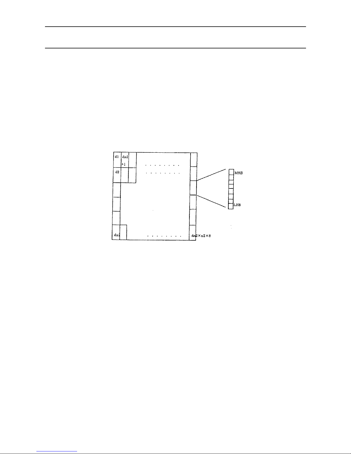
iDP3410 User's Manual
50 CITIZEN
GS "*" n1 n2 [d] n1 × n2 × 8
[Function] Defining the download, bit image
[Code] <1D>H <2A>H <n1> <n2> [<d>] n1 × n2 × 8
[Range] 1 ≤ n1 ≤ 45 0 ≤ n2 ≤ 24
Note) Take care that the number of data (n1×n2×8) is equal to or smaller than 2,048.
[Outline] This command defines the download bit image having the dots spec ified n1 and n2. The
number of horizontal dots is represented by n1 × 8 and that of vertical dots is represented
by n2 × 8, respectively. m denotes the number to be registered. (See a download bit
image printout.) d denotes the bit image data. Once the download bit image is defined, it
remains valid until it is redefined or the download deletion command (ESC DC2 n1 n2) is
executed.
Page 65

iDP3410 User's Manual
51 CITIZEN
GS / m
[Function] Printing the download, bit image
[Code] <1D>H <2F>H m
[Range] 0 ≤ m ≤ 255
[Outline] This command prints the bit image saved in the number specified with m.
[Caution] If the print buffer contains the data, this command will be ignored. If the bit image has not
been saved in the specified number, this command will be ignored.
Nothing is printed when m is other than 0,1,2 or 3.
Page 66

iDP3410 User's Manual
52 CITIZEN
13.2 STAR Mode
13.2.1 Command List
Command Function Code Page
1 ESC R n Selecting t he i nt ernat i on al ch aract er set 1BH 52H n 54
2 ESC 6 NOP 1BH 36H
3 ESC 7 NOP 1BH 37H
4 ESC M NOP 1BH 4DH
5 ESC P NOP 1BH 50H
6 ESC : NOP 1BH 3AH
7 SO Specifying the double width character 0EH 54
8 DC4 Canceling the double width character 14H 55
9 ESC E Specifying the highlight character 1BH 45H 55
10 ESC F Canceling the highlight character 1BH 46H 55
11 ESC - Specifying/Canceling the underline 1BH 2DH n 56
12 ESC _ NOP 1BH 5FH n
13 ESC 4 Specifying the red print 1BH 34H 56
14 ESC 5 Canceling the red print 1BH 35H 56
15 SI Specifying the inverted character 0FH 57
16 DC2 Canceling the inverted character 12H 57
17 LF Printing and paper feed 0AH 58
18 CR Printing 0DH 58
19 ESC z Setting the 1/6-inch line feed 1BH 7AH 58
20 ESC 0 NOP 1BH 30H
21 ESC a n n-line paper feed 1BH 61H n 59
22 FF Form feed (Change the page) 0CH 59
23 ESC C n Setting the n-line page length 1BH 43H n 59
24 ESC C 0 n Setting the n-inch page length 1BH 43H 00 n 60
25 VT Vertical tab 0BH 60
26 ESC B n1 n2 Setting the vertical tab position 1BH 42H n1 n2 61
27 ESC N n Setting the lower margin 1BH 4EH n 61
28 ESC 0 Canceling the lower margin 1BH 4FH 62
29 ESC 1 n Setting the left margin 1BH 6cH n 62
30 ESC Q [n] k NUL Setting the right margin 1BH 51H n 62
31 HT Horizontal tab 09H 63
32 ESC D n1 n2 Setting the horizontal tab position 1BH 44H n1 n2 64
33 ESC 1 Setting the 1/9-inch line feed width 1BH 31H 65
34 ESC A n NOP 1BH 41H n
35 ESC 2 Setting the 2/9-inch line feed width 1BH 32H 65
36 ESC J n NOP 1BH 4AH n
37 ESC K n1 <0> Specifying the 8-dot standard density bit image 1BH 4BH n1 00H 66
38 ESC L n1 n2 Specifying the 8-dot double density bit image 1BH 4CH n1 n2 67
39 ESC h n Specifying/Canceling the double height character 1BH 68H n 68
40 ESC & 0 n1 n2 Defining the download character 1BH 26H 00H n1 n2 69
41 ESC % n Specifying/Canceling the download character set 1BH 25H n 70
Page 67
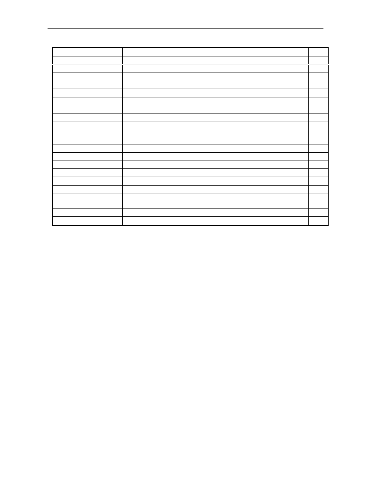
iDP3410 User's Manual
53 CITIZEN
Command Function Code Page
42 ESC BEL n1 n2 Setting the external device drive pulse width 1BH 07H n1 n2 71
43 BEL Driving command A for drawer-1 07H 71
44 FS Driving command B for drawer-1 1CH 72
45 SUB Driving command for drawer-2 1AH 72
46 RS Buzzer-on 1EH 72
47 CAN Canceling the print data 18H 73
48 DC3 Setting the deselect mode 13H 73
49 DC1 Setting the Select mode 11H 73
50 ESC U n
Selecting the Unidirectional/bidirectional print
mode
1BH 55H n 74
51 ESC @ Initializing the printer 1BH 40H 74
52 ENQ Enquiry 05H 75
53 STX Text start 02H 76
54 ETX Te xt end command 03H 76
55 ESC t n Selecting the character code table 1BH 74H n 78
56
ESC ⁄ n
Defining the message 1BH 2FH n
79
57 ESC DC3 Printing the message 1BH 13H n 79
58 ESC DC2 n1 n2
Deleting the download character, message bit
image
1BH 12H n1 n2
80
59 GS ∗ n1 n2 Defining the download, bit image 1DH 2AH n1 n2 81
60
GS ⁄ m
Printing the download, bit image 1DH 2FH m
82
Page 68
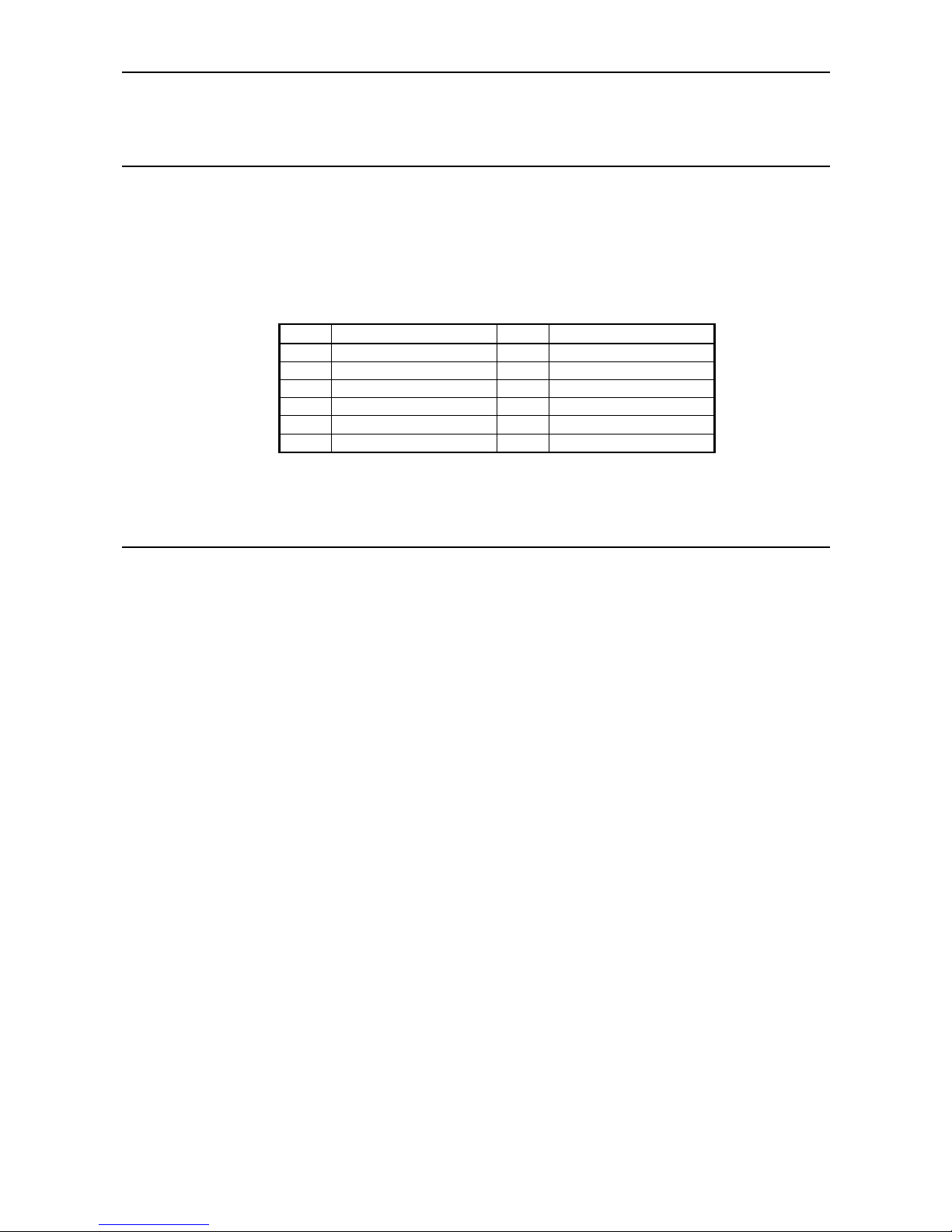
iDP3410 User's Manual
54 CITIZEN
Details
ESC “R” n
[Function] Selecting the international character set
[Code] <1B>H <52>H n
[Range] 0 ≤ n ≤ 10
[Outline] This command selects the international characters according to the value of n.
n Character Set n Character Set
0 U.S.A. 6 Italy
1 France 7 Spain
2 Germany 8 Japan
3U.K.9Norway
4 Denm ark I 10 Denmark II
5 Sweden
[Default] Depends upon DIP switch setting.
SO
[Function] Specifying the double width character
[Code] <0E>H
[Outline] The data following this command is printed doubled in the horizontal direction. Double
width characters remain valid until the double width character cancel command is entered,
but they are also cancelled after they are printed one line. Note that the double width
characters take up two ordinary characters worth of width.
Page 69

iDP3410 User's Manual
55 CITIZEN
DC4
[Function] Canceling the double width character
[Code] <14>H
[Outline] This command deselects the double width characters set with SO. The data following this
command will be printed in ordinary characters.
ESC "E"
[Function] Specifying the highlight character
[Code] <1B>H <45>H
[Outline] The data following this command is printed in highlight (Double) characters. The
highlight characters remain valid until the highlight character deselection command is
entered.
ESC "F"
[Function] Canceling the highlight character
[Code] <1B>H <46>H
[Outline] This command deselects the highlight characters set with ESC "E". The data following
this command will be printed in ordinary characters.
Page 70

iDP3410 User's Manual
56 CITIZEN
ESC "-" n
[Function] Specifying/Canceling the underline
[Code] <1B>H <2D>H n
[Outline] This command selects/deselects an underline. The underline is selected at n = 1 and
deselected at n = 0.
The space by the horizontal tab is not underlined.
ESC "4"
[Function] Specifying the red print
[Code] <1B>H <34>H
[Outline] This command prints its subsequent data in red. This command remains valid until the red
print deselection command is entered. Red and black characters cannot be mixed in one
line.
ESC "5"
[Function] Canceling the red print
[Code] <1B>H <35>H
[Outline] This command deselects red print.
Page 71

iDP3410 User's Manual
57 CITIZEN
SI
[Function] Specifying the inverted character
[Code] <0F>H
[Outline] This command selects and prints the inverted characters. Enter it at the beginning of one
line. Otherwise, it will be invalid. Erect and inverted characters cannot be mixed in one
line.
DC2
[Function] Canceling the Inverted character
[Code] <12>H
[Outline] This command deselects the inverted characters. Enter this command at the beginning of
one line.
Page 72

iDP3410 User's Manual
58 CITIZEN
LF
[Function] Printing and paper feed
[Code] <0A>H
[Outline] If the print buffer contains the data, this command will feed the line after printing. If not,
the command only feeds the line.
CR
[Function] Printing
[Code] <0D>H
[Outline] This command prints the data. If the DIP switch segments 1 to 6 are set to OFF, the
printer will print the data in the print buffer and feed the paper by one line. If they are set
to ON, the printer will print the data in the print buffer and will not feed the paper.
ESC "z"
[Function] Setting the 1/6-inch line feed width
[Code] <1B>H <7A>H
[Outline] This command sets the line feed width to 1/6 inch (Default).
Page 73

iDP3410 User's Manual
59 CITIZEN
ESC "a" n
[Function] Setting the n-line paper feed
[Code] <1B>H <61>H n
[Range] 1 ≤ n ≤ 127
[Outline] This command feeds the paper by the number of lines specified with n. You can set n = 1
to 127 lines. If the print buffer contains the data, use of this command feeds the paper by
n-lines after printing the data.
FF
[Function] Form feed (Changing the page)
[Code] <0C>H
[Outline] This command searches for the head of the next page after printing the data in the print
buffer.
ESC "C" n
[Function] Setting the n-line page length
[Code] <IB>H <43>H n
[Range] 1 ≤ n ≤ 255
[Outline] Sets the 1-page length to n-lines.
[Default] n = 42
Page 74

iDP3410 User's Manual
60 CITIZEN
ESC "C" <0> n
[Function] Setting the n-inch page length
[Code] <1B>H <43>H <0> n
[Range] 1 ≤ n ≤ 127
[Outline] This command sets the length of one page to n-inches.
[Default] n = 42
VT
[Function] Vertical tab
[Code] <0B> H
[Outline] This command feeds the paper to the next vertical tab position. It cannot be fed unless the
vertical tab position has been set. If the current position is equal to or greater than the
maximum set vertical tab position, it will be fed to the head of the next page.
Page 75

iDP3410 User's Manual
61 CITIZEN
ESC "B" [n]k NUL
[Function] Setting the vertical tab position
[Code] <1B>H <42>H [n]k <00>
[Range] 1 ≤ n ≤ 255
1 ≤ k ≤ 16
[Outline] This command cancels the already set vertical tab positions and sets new vertical tab
positions. They are set in the ascending order and ends with <00>. Up to 16 vertical tabs
can be set. If the tab setting position <nK> is equal or smaller than the preceding set
position <nk-1>, it is assumed that setting of the vertical tabs has been completed.
ESC "N" n
[Function] Setting the lower margin
[Code] <1B>H <4E>H n
[Range] 0 ≤ n ≤ 255
[Outline] This command sets the n-line lower margin.
[Default] n = 0
Page 76

iDP3410 User's Manual
62 CITIZEN
ESC "O"
[Function] Canceling the lower margin
[Code] <1B>H <4F>H
[Outline] This command deselects the set lower margin.
ESC "l" n
[Function] Setting the left margin
[Code] <1B>H <6C>H n
[Range] 0 ≤ n ≤ (Right margin - 2)
[Outline] This command sets the left margin and printing starts from the column next to the set
margin.
ESC "Q" n
[Function] Setting the right margin
[Code] <1B>H <51>Hn
[Range] 2 ≤ n ≤ (Max. print columns)
[Outline] This command sets the right margin and printing is performed up to n-columns.
Page 77

iDP3410 User's Manual
63 CITIZEN
HT
[Function] Horizontal tab
[Code] <09>H
[Outline] This command moves a printing position to the preset next horizontal tab position. This
command will be ignored unless there is the next horizontal tab position.
Page 78

iDP3410 User's Manual
64 CITIZEN
ESC "D" [n] k NUL
[Function] Setting the horizontal tab position
[Code] <1B>H <44>H [n] k <00>H
[Range] 1 ≤ n ≤ Max. print columns – 1
1 ≤ k ≤ 16
[Outline] This command sets the horizontal tab positions. n indicates the number of lines fr om the
head of the line to the horizontal tab setting position; n equals the set column position - 1."
k indicates the number of horizontal tab positions to be set.
The tab position is set at the character width × n from the head of the line. The character
width at this time includes the right space of the character and will be doubled if the
double width characters are specified.
The data <n>k indicating the set position is entered in the ascending order and ends with
<00>H. ESC D NUL clears all the set ta b positions. After c learing the ta b positions, HT
will be ignored.
[Caution] I f the data <n>k is equal to or smaller than the preceding data < n>k - 1, it is a ssumed that
horizontal tab setting has been completed. In that case, the subsequent data will be
processed as regular one.
Up to 16 tab positions can be set. If the data exceeds this limit, it will be processed as
regular data. If the data <n>k exceeds the one-line print range, the set column position
will equal the maximum print columns + 1.
If the character width is changed after setting the horizontal tab positions, they will not
change.
Page 79

iDP3410 User's Manual
65 CITIZEN
ESC "1"
[Function] Setting the 1/9-inch line feed width
[Code] <1B>H <31>H
[Outline] This command sets the line feed width to 1/9 inch.
ESC "2"
[Function] Setting the 2/9-inch line feed width
[Code] <1B>H <32>H
[Outline] This command sets the line feed width to 2/9 inch.
Page 80
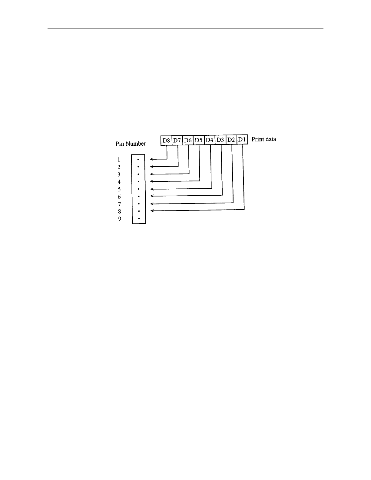
iDP3410 User's Manual
66 CITIZEN
ESC "K" n1 <0> m1 m2 ...
[Function] Specifying the 8-dot standard density bit image
[Code] <1B>H <4B>H n1 <00>H m1 m2 ...
[Range] 1 ≤ n1 ≤ 378/2
[Outline] This command prints the bit image by the number of data specified with n1. Printing w ill
be unidirectional. The surplus data exceeding the printable quantity in one line will be
ignored. The printer will automatically return to the character mode after printing the bit
image.
Page 81

iDP3410 User's Manual
67 CITIZEN
ESC "L" n1 n2 m1 m2 ...
[Function] Specifying the 8-dot double density bit image
[Code] <1B>H <4C>H n1 n2 m1 m2 ...
[Range] 1 ≤ n1 + 256 × 2 ≤ 378
[Outline] This command prints the 8-dot double density (Half-dot print) bit ima ge. Printing will be
unidirectional. The surplus data exceeding the printable quantity in one line will be
ignored. The printer will automatically return to the character mode after printing the bit
image.
The relations between the printing head pin numbers and the data are the same as the 8-dot
standard density bit image command. When printing the double density bit image, the
horizontally adjacent dots cannot be printed.
Page 82
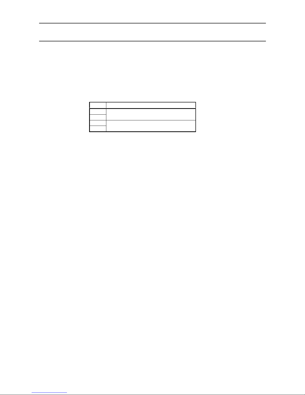
iDP3410 User's Manual
68 CITIZEN
ESC "h" n
[Function] Specifying/Canceling the double height character
[Code] <1B>H <68>H n
[Outline] The data following this command is printed in double height characters, except the bit
image mode <ESC> "K" and <ESC> "L". In combination with the <SO> command, this
command can print double height, double width characters.
It cannot be combined with the inverted character command, <SI>. The double height
characters and ordinary characters shall be bottom-justified.
n Double height character command
0
30
Deselects
1
31
Selects
Page 83
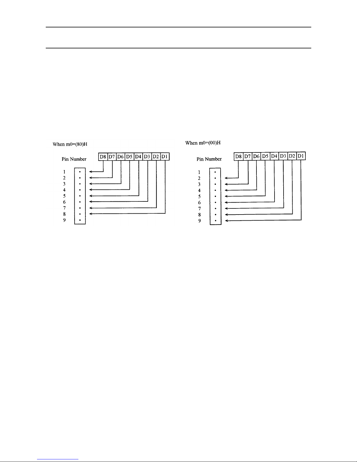
iDP3410 User's Manual
69 CITIZEN
ESC "&" <O> n1 n 2 m0 m1 m2 m3 m4 m5 m6 m7 m8 m9 ] n2 - n1 + 1
[Function] Defining the download character set
[Code] <1B>H <26>H <00>H n1 n2 [m0 m1 ... m5 m6 m7 m8 m9] n2 - n1 + 1
[Range] 32 ≤ n1≤ n2 ≤ 255 m0 = 0 or m0 = 128
[Outline] This command defines he download characters. n1 is a character c ode to start definition
and n2 is to end definition, respectively. When defining only one character, set n1 = n2.
You can define the ASCII codes ranging from 32 to 255.
The horizontally adjacent dots cannot be printed. Once the download bit image is defined,
it remains valid until it is redefined or the download deletion command(ESC DC2 n1 n2)
is executed.
Horizontal adjacent dots cannot be printed.
Page 84
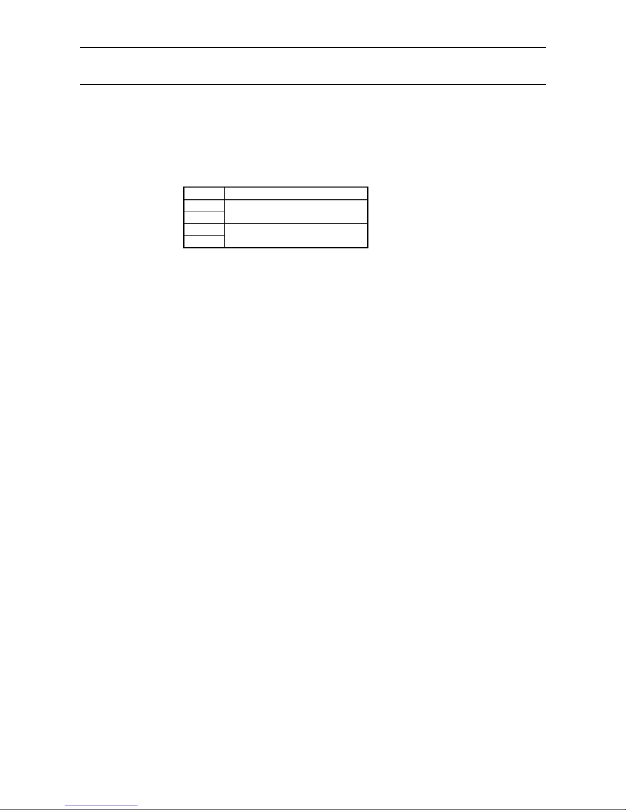
iDP3410 User's Manual
70 CITIZEN
ESC "%" n
[Function] Specifying/Canceling the download character set
[Code] <1B>H <25>H n
[Outline] This command selects/deselects the download character set. The download characters
cannot be printed by simply defining them with the above-mentioned ESC & 0 command.
To print them, send this command to the printer.
n Download Character Set
0
30
Deselects
1
31
Selects
Page 85
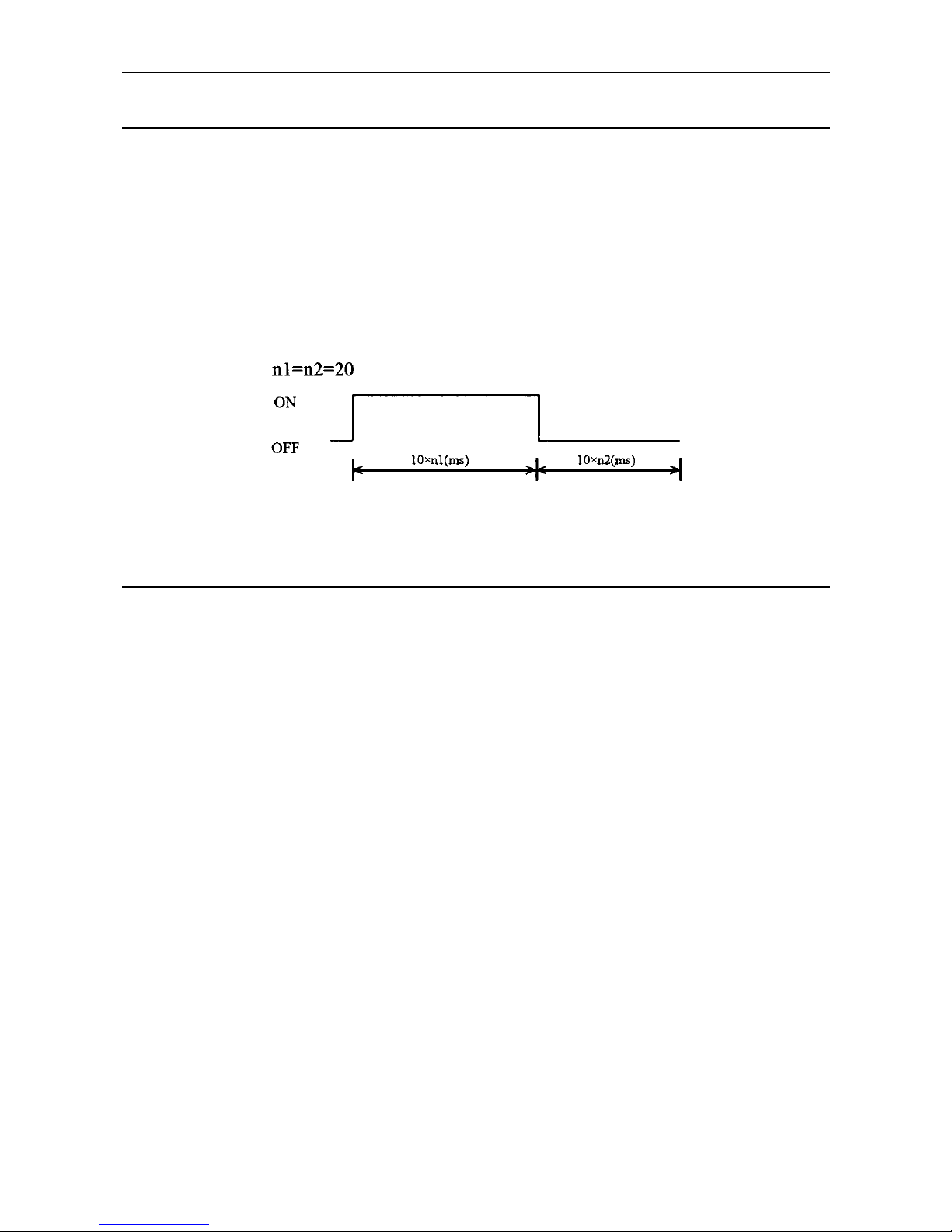
iDP3410 User's Manual
71 CITIZEN
ESC BEL n1 n2
[Function] Setting the external device drive pulse width
[Code] <1B>H <07>H n1 n2
[Range] 1 ≤ n1 ≤ 127
1 ≤ n2 ≤ 127
[Outline] This command sets the power-on time to drive an external device(Cash drawer).
Power-on time = n1 × 10 (ms)
Delay time = n2 × 10 (ms)
To actually drive the drawer, use the <BEL> and <FS> commands.
[Default] n1 = n2 = 20 (200ms)
BEL
[Function] Driving command A for drawing-1
[Code] <07>H
[Outline] This command drives the drawer connector no. 2 pin under the condition set with the
<ESC><BEL> n1 n2 command. This command is executed in order of entry into the
input buffer.
Page 86

iDP3410 User's Manual
72 CITIZEN
FS
[Function] Driving command B for drawer-1
[Code] <1C>H
[Outline] This command drives the drawer connector no. 2 pin under the condition set with the
<ESC><BEL> n1 n2 command.
SUB
[Function] Driving command for drawer-2
[Code] <1A>H
[Outline] As soon as this command is received, the drawer connector no. 5 pin is driven. The
power-on time is 200 ms O N and 200 ms OFF stationary. The drawers 1 and 2 cannot be
driven simultaneously.
RS
[Function] Buzzer-on
[Code] <1E>H
[Outline] This command emits a short warning sound from the printer.
Page 87

iDP3410 User's Manual
73 CITIZEN
CAN
[Function] Canceling the print data
[Code] <18>H
[Outline] This command clears the input buffer and print buffer. In the STX-EXT mode of the serial
interface printer, the command clears the data in the data buffer and ends the STX-ETX
mode.
DC3
[Function] Setting the deselect mode
[Code] <13>H
[Outline] If the printer receives <DC3>, it will ignore the subsequent data. The Deselect mode is
cancell ed by <DC 1 >.
DC1
[Function] Setting the select mode
[Code] <11H>
[Outline] If the printer receives this command, it will save the subsequent data in the input buffer.
Page 88
iDP3410 User's Manual
74 CITIZEN
ESC "U" n
[Function] Selecting the Unidirectional/Bidirectional print mode
[Code] <1B>H <55>H n
[Range] 0 ≤ n ≤ 255
[Outline] This commands selects or deselects unidirectional print.
n0 = 0 Bidirectional print
n0 = 1 Unidirectional print
ESC "@"
[Function] Initializing the printer
[Code] <1B>H <40>H
[Outline] This command cancels various conditions set after power-on to initializes the printer to the
conditions having existed at power-on. However, the input buffer is not initialized.
Page 89
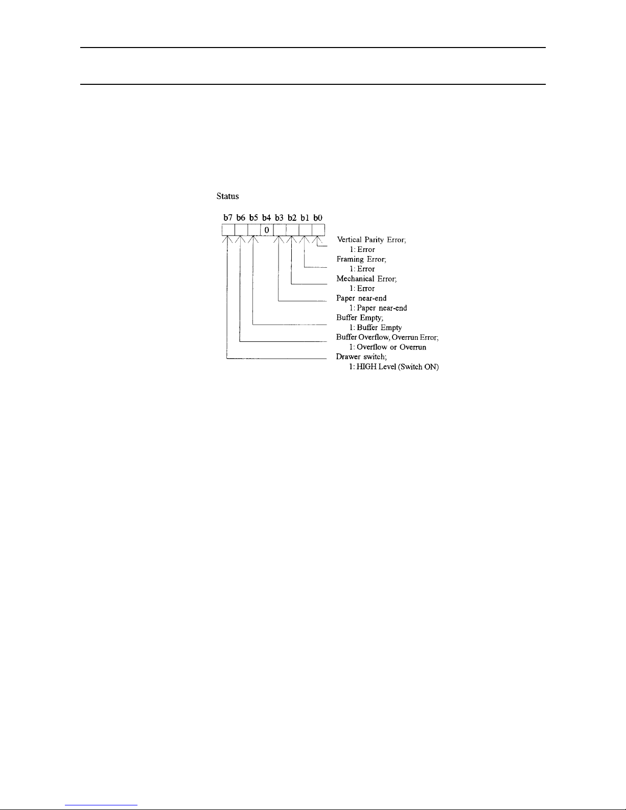
iDP3410 User's Manual
75 CITIZEN
ENQ
[Function] Enquiry
[Code] <05>H
[Outline] This command is valid only for the serial interface. The printer sends the status
information. If this command is entered after receiving the text information in the STXETX mode, the printer will send the status information and check byte.
Page 90

iDP3410 User's Manual
76 CITIZEN
STX
[Function] Text start
[Code] <02>H
[Outline] This command is valid only for the serial interface. It effectuates the STX-ETX mode.
ETX
[Function] Text end
[Code] <03>H
[Outline] This command is valid only for the serial interface. It ends the STX-ETX mode and prints
the data.
Page 91
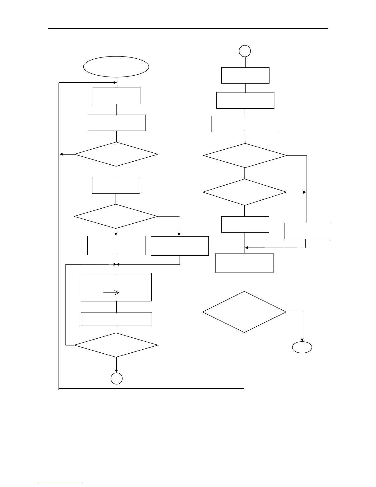
iDP3410 User's Manual
77 CITIZEN
* ETX-STX Mode
STX/ETX Mode Start
Sends ENQ
Receives Status
Data Buffer Empty ?
Sends STX
Odd Parity Check ?
Sets Test Byte To
FFH
Sets Test Byte To
00
Exclusive ORs Test Byte
and Sent Data
Test Byte
Sends Data to Printer
Last Data in 1 Block ?
1
1
NO
YES
YES
NO
YES
Receives Status
Receives Check Byte
Sends ETX
STX-ETX
Mode End
NO
YES
Status Error ?
Sends ENQ
Check Byte
= Test B
y
te ?
YES
NO
YES
(Print)
Sends CAN
STX-ETX Mode Data
Block Ready to Send ?
NO
RET
NO
Page 92
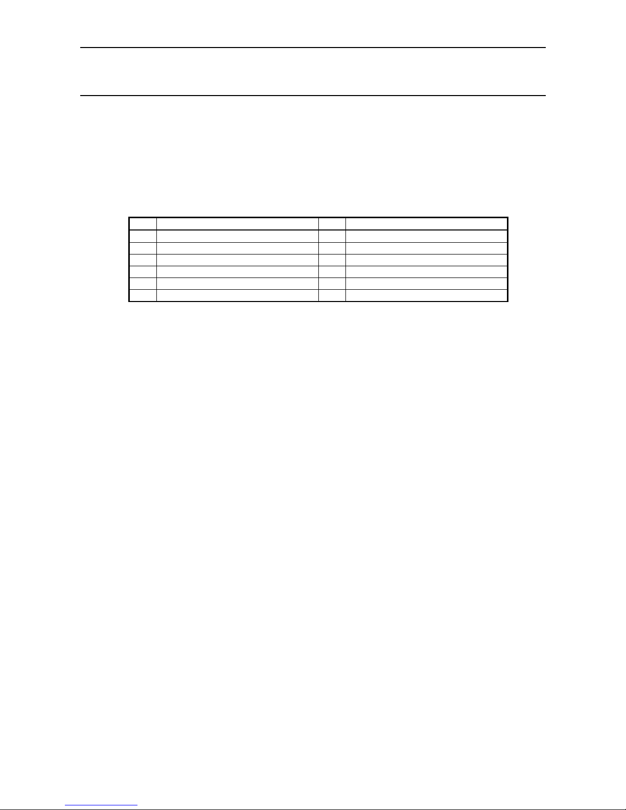
iDP3410 User's Manual
78 CITIZEN
ESC "t" n
[Function] Selecting the character code table
[Code] <1B>H <74>H n
[Range] 0 ≤ n ≤ 255
[Outline] This command selects Page-n of Character Code Table.
[Default] Depends on DIP switch setting.
n Character Code Table N Character Code Table
0 STAR International 6 Code Page 852 (Eastern Europe)
1 STAR Domestic 7 Code Page 866 (Russia)
2 Code Page 850 (Multilingual) 8 Code Page 857 (Turkey)
3 Code Page 860 (Portugal) 9 Windows Code
4 Code Page 863 (Canada-French)
5 Code Page 865 (Norway) 255 Space Page (For user setting)
Page 93

iDP3410 User's Manual
79 CITIZEN
ESC "/" n "data" CR or LF
[Function] Defining the message
[Code] <1B>H <2F>H n "data" CR or LF
[Range] 1 ≤ n ≤ 10
[Outline] This command can define up to a 50-byte message in one line. If the value of n is
specified beyond the range, the data following n will be treated as the print data.
Once the message is defined, it remains valid until it is redefined. The data should end
with CR (0DH) or LF (0AH). If the data exceeds 50 bytes, the subsequent data will be
treated as the print data.
Once the message is defined, it remains valid until it is redefined or the download deletion
command (ESC DC2 n1 n2) is executed.
ESC "DC3" n
[Function] Printing the message
[Code] <1B>H <13>H n
[Range] 1 ≤ n ≤ 10
[Function] This command prints a message. If the value of n is specified beyond the range, the
message will not be printed.
Page 94
iDP3410 User's Manual
80 CITIZEN
ESC DC2 n1 n2
[Function] Deleting the download character, message, bit image
[Code] <1B>H <12>H n1 n2
[Range] 0 ≤ n1≤ 3
0 ≤ n2 (Specify 0 at n1 = 0)
(1 ≤ n2 ≤ 10 at n1 = 1)
(32 ≤ n2 ≤ 224 at n1 = 2)
(Specify 0 at n1 = 3)
[Outline] This command deletes the downloaded characters, message, and bit image.
n 1 Object Deleted
0 All(Message, characters, bit image)
1 Download message
2 Download characters
3 Download bit image
With n2, specify which data of the function specified with n1 should be deleted.
n2 = 0 Deletes all the download function specified with n1.
n2≠0 Deletes the data downloaded at the value specified with n2 (Value specified
when saving with each download command), of the download function
specified with n1.
Note)No meaning when n1 = 0 is set.
Page 95
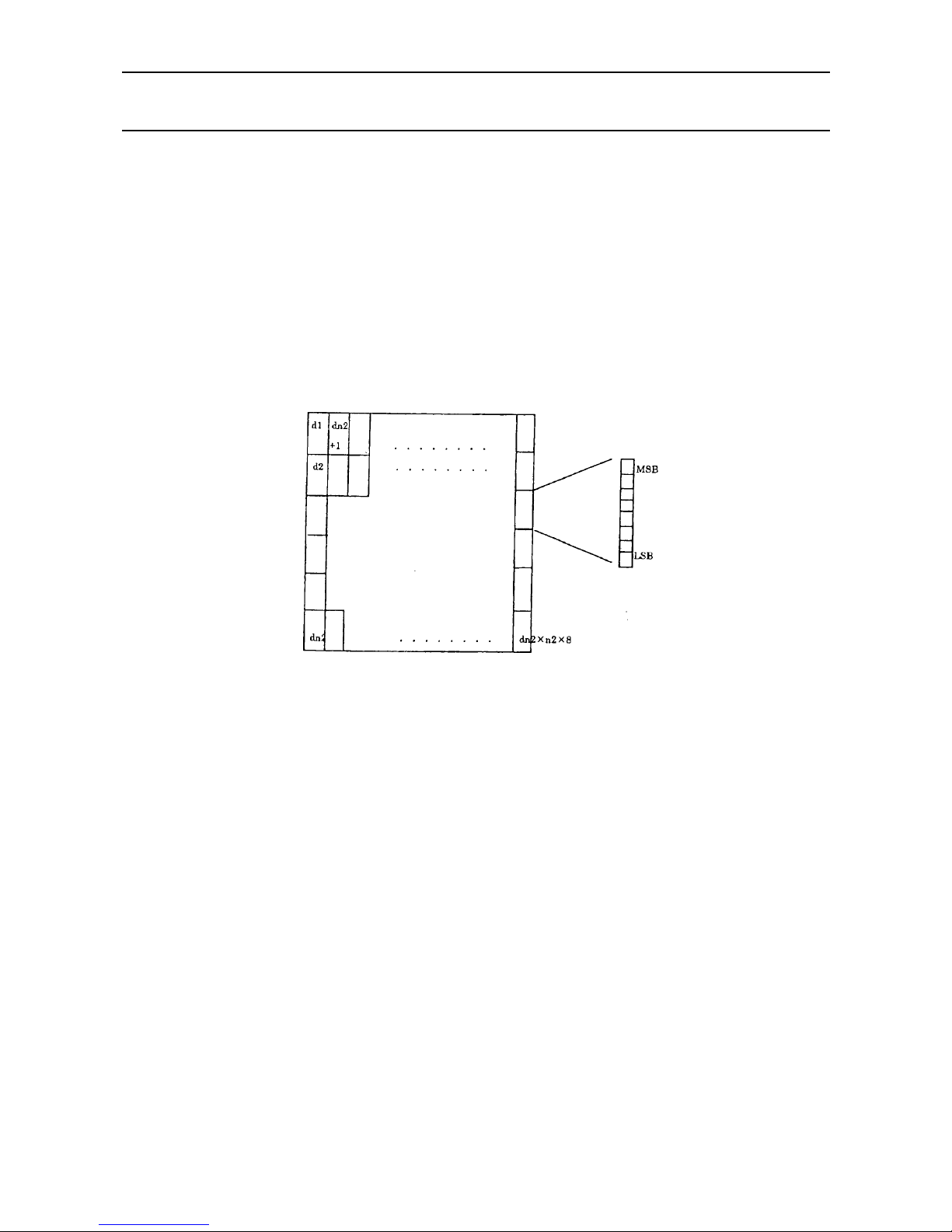
iDP3410 User's Manual
81 CITIZEN
GS "*" n1 n2 [d] n1 × n2 × 8
[Function] Defining the download, bit image
[Code] <1D>H <2A>H <n1> <n2> [<d>] n1 × n2 × 8
[Range] 1 ≤ n1 ≤ 45 0 ≤ n2 ≤ 24
Note)Take care that the number of data(n1×n2×8) is equal to or smaller than 2,048.
[Outline] This command defines the download bit image having the dots spec ified n1 and n2. The
number of horizontal dots is represented by n1 × 8 and that of vertical dots is represented
by n2 × 8, respectively. m denotes the number to be registered. (See a download bit
image printout.) d denotes the bit image data. Once the download bit image is defined, it
remains valid until it is redefined or the download deletion command(ESC DC2 n1 n2) is
executed.
Page 96

iDP3410 User's Manual
82 CITIZEN
GS / m
[Function] Printing the download, bit image
[Code] <1D>H <2F>H m
[Range] 0 ≤ m ≤ 255
[Outline] This command prints the bit image saved in the number specified with m.
[Caution] If the print buffer contains the data, this command will be ignored. If the bit image has not
been saved in the specified number, this command will be ignored.
Nothing is printed when m is other than 0,1,2 or 3.
Page 97
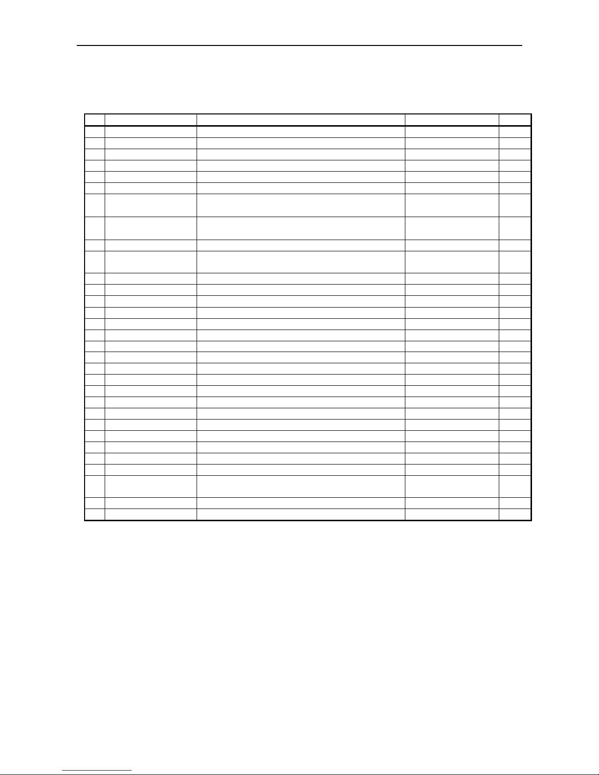
iDP3410 User's Manual
83 CITIZEN
13.3 ESC/POS Commands
13.3.1 Command List
Command Function Code Page
1 HT Horizontal tab 09H 84
2 LF Printing and paper feed 0AH 84
3 CR Printing 0DH 85
4 ESC " " n Setting the character right space 1BH 20H n 85
5 ESC ! n Setting print mode batch 1BH 21H n 86
6 ESC % n Specifying/Canceling the download character set 1BH 25H n 87
7
ESC & s n m
[a[p] s
× a]
Defining the download character set
1BH 26H s n m
[a[p] a×a] m-n+1
88
8
ESC
∗ m n1 n2
[d] n1 + 256 × n2
Specifying the bit image mode
1BH 2AH m n1 n2
[d] n1 + 256×n2
89
9 ESC 2 Setting the 1/6-inch line feed rate 1BH 32H n 90
10 ESC 3 n
Setting the line feed width in minimum pitch
increments
1BH 33H n 90
11 ESC < NOP 1BH 3CH
12 ESC @ Initializing the printer 1BH 40H 90
13 ESC D [n] k NUL Setting the Horizontal tab position 1BH 44H [n] k 00 91
14 ESC J n NOP 1BH 4AH n
15 ESC R n Selecting the international character set 1BH 52H n 92
16 ESC U n Specifying/Canceling the unidirectional print mode 1BH 55H n 93
17 ESC c 0 n NOP 1BH 63H 30 n
18 ESC c 5 n Selecting the panel switch enable/disable 1BH 63H 35H n 94
19 ESC d n Printing and n-line paper feed 1BH 64H n 94
20 ESC p m n1 n2 Specifying the pulse generation 1BH 70H m n1 n2 95
21 ESC r n Selecting the printing color 1BH 72H n 96
22 ESC t n Selecting the character code table 1BH 74H n 96
23 ESC u n Sending the status for peripheral device 1BH 75H n 97
24 ESC v Sending the printer status 1BH 76H 98
25 ESC { n Specifying/Canceling the inverted character print 1BH 7BH n 99
26 GS E n NOP 1DH 45H n
27 ESC / n Defining the message 1BH 2FH n 99
28 ESC DC3 n Printing the message 1BH 13H n 100
29 ESC DC2 n1 n2
Deleting the download character, message, bit
image
1BH 12H n1 n2 101
30 GS ∗ n1 n2 Defining the download, bit image 1DH 2AH n1 n2 102
31 GS / m Printing the download, bit image 1DH 2FH m 103
Page 98

iDP3410 User's Manual
84 CITIZEN
Details
HT
[Function] Horizontal tab
[Code] <09>H
[Outline] This command moves a printing position to the next horizontal tab position. If the next
horizontal tab position is not set, this command will be ignored.
[Caution] The horizontal tab position is set by <ESC> D. Initial setting of the horizontal tab position
is every 8 characters (9th, 17th, 25th culomns, and so on) of the 7×9 font.
LF
[Function] Printing and paper feed
[Code] <0A>H
[Outline] This command prints one line worth of the data saved in the print buffer and feeds the line
based on the set line feed value. The head of the line is assumed to be the next print start
position.
Page 99

iDP3410 User's Manual
85 CITIZEN
CR
[Function] Printing
[Code] <0D>H
[Outline] This command prints the data. If the DIP switch segments 1 to 6 are set to OFF, the
printer will print the data in the print buffer and feed the paper by one line. If they are set
to ON, the printer will print the data in the print buffer and will not feed the paper.
ESC " " n
[Function] Setting the character right space
[Code] <1B>H <20>H n
[Range] 0 ≤ n ≤ 32
[Outline] This command sets the right space of the character.
[Caution] In the double width mode, the right space will be double the set amount. Set the space in
increments of half dot.
[Default] n = 0
Page 100
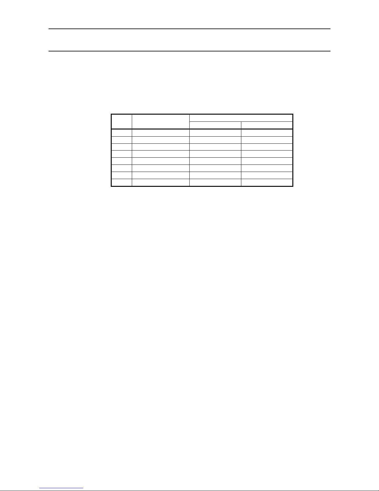
iDP3410 User's Manual
86 CITIZEN
ESC "!" n
[Function] Setting the print mode batch
[Code] <1B>H <21>H n
[Range] 0 ≤ n ≤ 255
[Outline] Sets the print mode. "n" (Each bit) has the following meanings.
Value s
Bit Function
01
0 Undefined −−
1 Undefined −−
2 Undefined
−−
3 High-lighting Canceled Specified
4 Double height Canceled Specified
5 Double width Canceled Specified
6 Undefined
−−
7 Underline Can celed Specified
[Caution] The entire character print width is underlined, but the portion skipped by HT is not. If
both double height and double width are selected, the characters will be quadrupled. If the
double width characters are selected, some dots may not be printed depending on the
preceding one.
When printing the double height characters, there will be less shear in unidirectional
printing.
[Default] n = 0
 Loading...