

Citiwell Orbitor OR7500, Orbitor OR6000 Series Instructions And Owner's Manual

OR6000 Series
4.5” Reflector Telescope
(Model 7500)
Instructions
and
Owner’s Manual
Manual Part # 262504
Made in China
Revised September 2003
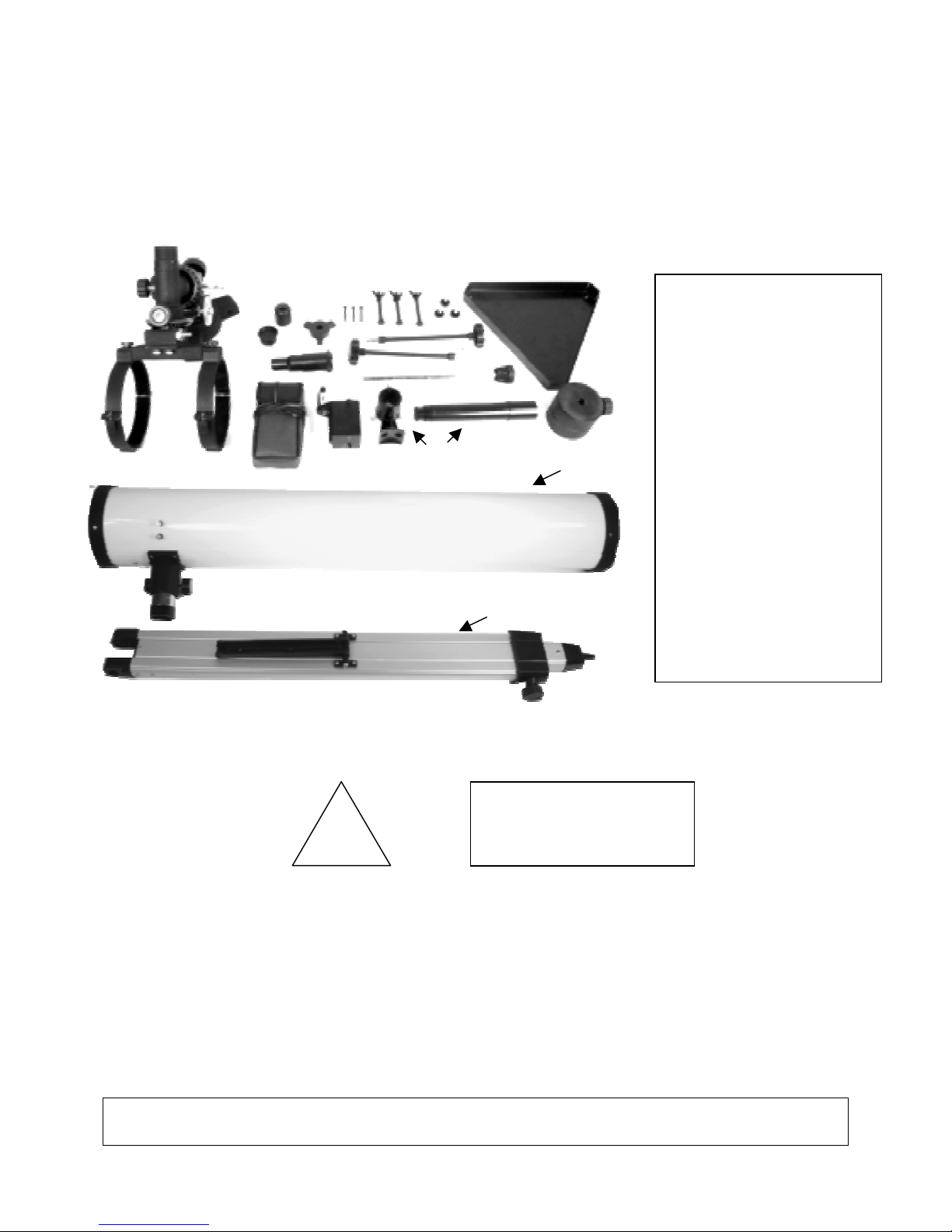
Parts of your new telescope:
D
N
M
G
C
H
F
L
B
K
E
A
J
O
P
A. Finder scope and bracket
B. Slow-motion controls (2)
C. Equatorial motor
D. Battery pack & c ord
E. Counterweight shaft
F. Tripod leg bolts (3)
G. Tripod leg brace hub
H. Tripod leg brace bolts
I. Equatorial mount assembly
(with cradle rings attached)
J. Counterweight
K. Accessory tray
L. Accessory tray screws (3)
M. 2X Barlow lens
N. Eyepieces (2)
O. Optical tube
P. Tripod leg (3)
!
Small parts. Not
WARNING!
NEVER aim your telescope at the sun or even close to the sun!
Instant and irreversible damage can occur,
including blindness!
Do not let children use any telescope without adult supervision.
NOTE: Actual parts and components may vary slightly in color or style from
pictures shown.
2
WARNING!
CHOKING HAZARD
suitable for
children under 3 years.
Introduction
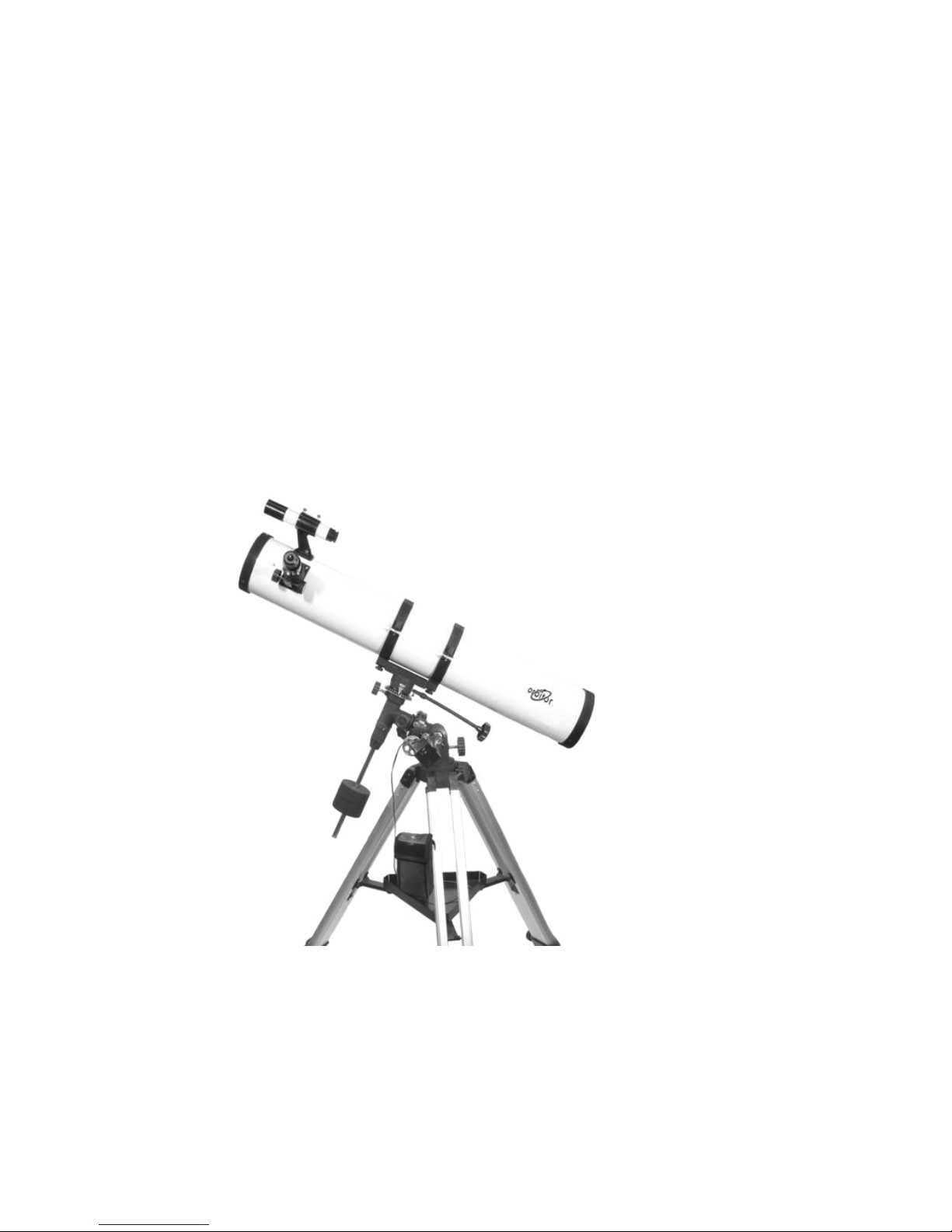
Congratulations on your purchase of a new OR7500 telescope. With proper care and
handling of your telescope, you will enjoy the pleasure of looking at nature’s wondrous
sights through the eye of this instrument for many years.
Your telescope has been designed to provide views of the moon’s craters, Jupiter’s
major moons, and Saturn’s rings, in addition to dozens of galaxies, star clusters, and
nebulae.
To obtain the best performance from your telescope, please read this manual carefully
and completely.
FOR MORE INFORMATION AND ANSWERS TO ANY QUESTIONS, PLEASE GO TO
OUR WEBSITE: www.citiwellint.com
NOTE: When you remove the cradle rings and the protective plastic bag from the
telescope tube there may be a residue on the tube. To remove this residue use a warm,
soapy cloth and carefully clean the area, being careful not to let water enter the tube.
Dry completely with a soft towel and then buff with a soft cloth. You may polish the tube
with a good quality spray wax. Do not spray the wax directly onto the tube. Spray it
lightly on the polishing cloth. Do not use excessive force as scratches may result.
3
ASSEMBLY
1) Carefully remove all parts from the cardboard cartons and lay them on a table or
on the floor in order to take an inventory of all the pieces. Keep your box for storage
or in case you ever need to ship your telescope.
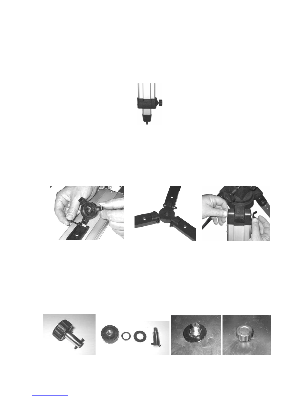
2) Extend the tripod legs, and lock each one at the desired height with the tripod leg
adjustment knobs. (See Fig. 1)
(Fig. 1)
3) If your tripod is not fully assembled you need to attach the tripod braces (attached
to each leg) to the tripod leg brace hub using the 3 thin bolts with nuts. (See Fig. 2A)
The completed assembly is shown in Figure 2b. Then attach each leg to the
equatorial mount assembly with supplied tripod leg bolts and wing nuts. (See Fig. 2)
(Note that some telescopes may have round plastic tighteners in place of wing nuts.)
(Fig. 2a) (Fig. 2b) (Fig. 2c)
4) Locate the tray attachment bolt (Fig. 3). Dis-assemble it as shown in Figure 3a by
turning the round knob counter-clockwise. Insert the chrome shaft upward through
the center of the tripod leg braces and up through the hole in the center of the
triangle-shaped accessory tray. While holding the shaft in place from underneath,
place the crinkly spring washer and the larger solid metal washer over the shaft as
shown in Figure 4. Then place the round knob over the shaft and turn clockwise until
tight. (See Fig. 4a)
(Fig. 3) (Fig. 3a) (Fig. 4) (Fig. 4a)
4
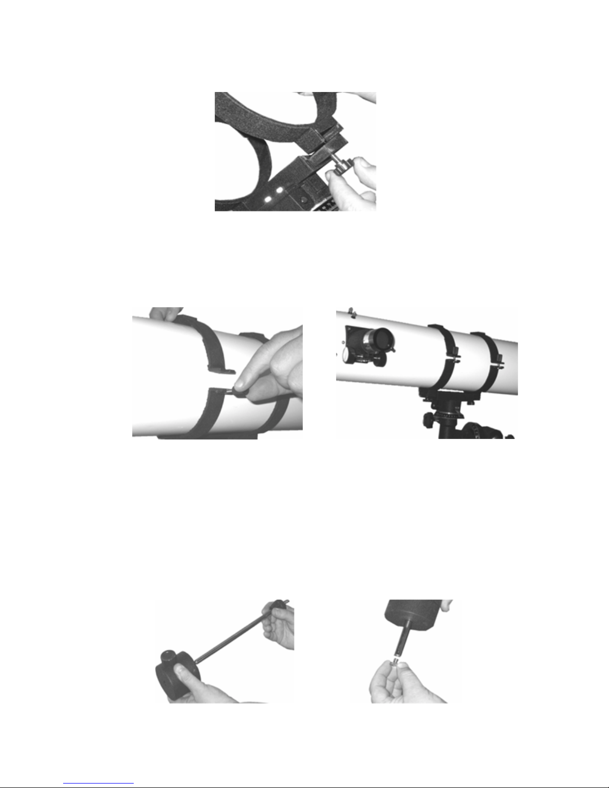
5) If your equatorial mount assembly does not have the cradle rings attached, you need
to attach the cradle rings to the equatorial mount assembly base with the bolts as
shown in Fig. 5.
(Fig. 5)
6) Open the cradle rings and place the optical tube inside. Close the rings around the
optical tube and tighten the bolts to hold the optical tube in place. Make sure the tube
is positioned and facing the same direction as in the illustration. (See Fig. 6 and 7)
(Fig. 6) (Fig. 7)
7) The counterweight balances your telescope and makes it easy to adjust and
position. Hold the counterweight in your hand so you can see through the hole in the
weight. Make sure that the black tightening knob on the counterweight is facing
down. If when you look through the counterweight you see that the hole is blocked by
a small metal rod, slowly turn the tightening knob counterclockwise to loosen it until
you see that the hole is clear. Insert the counterweight shaft through the
counterweight and attach and tighten the screw at the end of the shaft. Then turn the
counterweight tightening knob clockwise to secure it. (See Fig. 8 and 9)
(Fig. 8) (Fig. 9)
5
 Loading...