

Citiwell NG76AZ Owner's Manual

114AZ Telescope
Instructions
and
Owner’s Manual
A
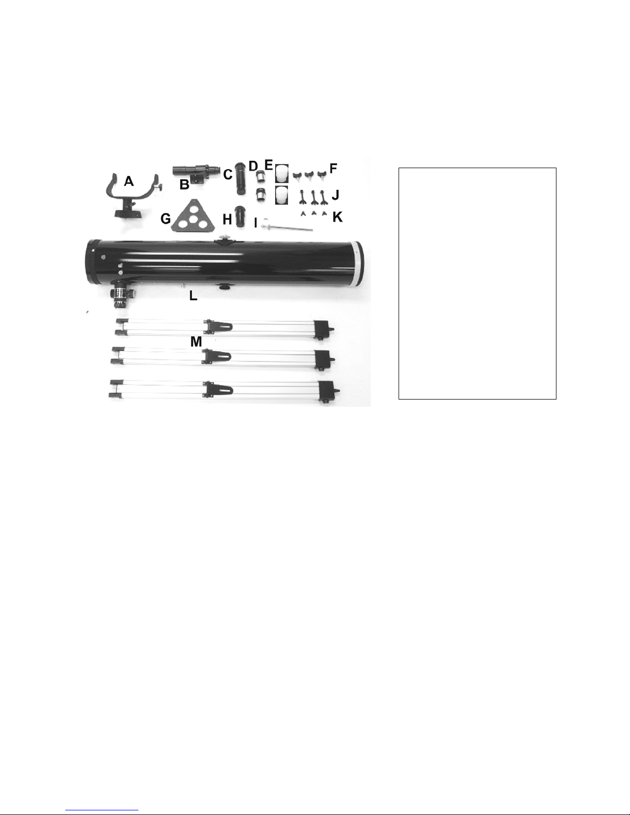
Parts of your 114AZ Telescope:
K
. Yoke
B. Finder scope with bracket
C. Image erector
D. Eyepieces (2)
E. Eyepiece cases (2)
F. Tripod leg adjustment bolts (3)
G. Accessory tray
H. 3X Barlow lens
I. Vertical fine adjustment rod
J. Tripod leg attachment bolts and
wing nuts (3)
K. Accessory tray attachment screws
and wing nuts (3)
L. Optical tube assembly
M. Tripod legs (3)
Colors of some components may vary from those shown in this manual.
WARNING!
NEVER aim your telescope at the sun or even close to the sun!
Instant and irreversible damage can occur,
including blindness!
Do not let children use any telescope without adult supervision.
2
Introduction
Congratulations on your purchase of a new telescope. With proper care and handling
of your telescope, you will enjoy the pleasure of looking at nature’s wondrous sights
through the eye of this instrument for many years.
This telescope has been designed to provide views of the moon’s craters, Jupiter’s
major moons, and Saturn’s rings, in addition to dozens of galaxies, star clusters, and
nebulae.
As a terrestrial (land) telescope, this instrument delivers great views of mountains,
valleys, and many other features of the world around us. You can also use your
telescope to study animals and landscapes at a distance. To obtain the best
performance from your telescope, please read this manual carefully and completely.
CHOKING HAZARD
Small parts. Not
children under 3 years.
!
WARNING!
suitable for
3
ASSEMBLY
1) Carefully remove all parts from the cardboard cartons and lay them on a table or
on the floor in order to take an inventory of all the pieces. Keep your box for storage
or in case you ever need to ship your telescope.
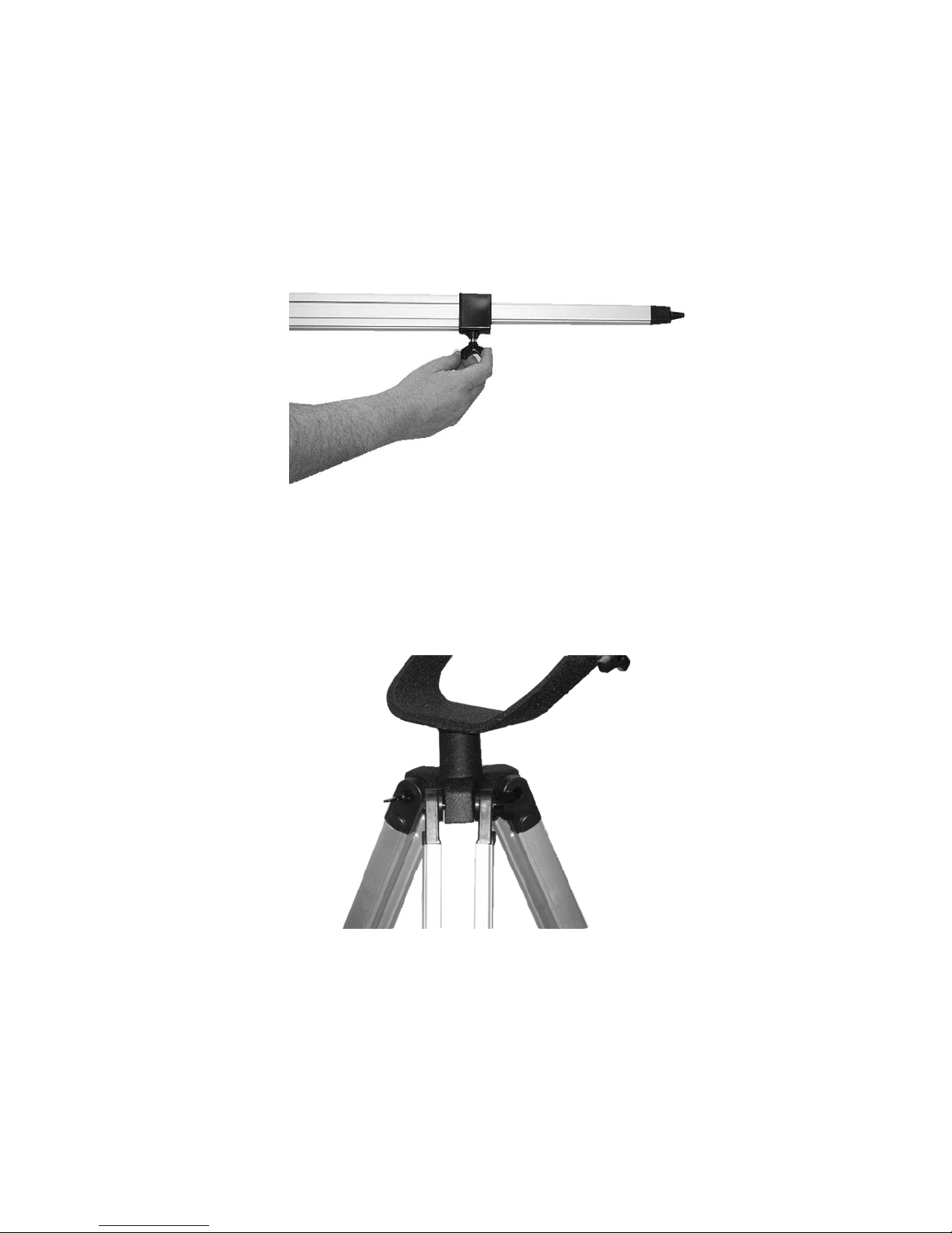
2) Extend the legs, and lock each one at the desired height with the supplied tripod
adjustment knob (See Fig. 1).
(Fig. 1)
3) Connect all three tripod legs to the yoke with the supplied tripod leg attachment
bolts, washers, and wing nuts. Each leg has a hinged black metal flange located
halfway down its length. The legs should be positioned so that these hinged flanges
are facing the inside of the tripod. Note that there are two black plastic spacers inside
the top sections of each leg (See Fig. 2).
(Fig. 2)
4) Attach the accessory tray to the tripod by inserting an accessory tray screw
downward through each of the three small holes located near the edge of the
accessory tray. Lift up the black metal accessory tray bracket on one tripod leg so
that it is at a right angle to the leg. Push the accessory tray screw through the
accessory tray and then through the slot in the accessory tray bracket (See Fig. 3).
Place a washer, then a wing nut over the screw and tighten the wing nut finger tight.
Repeat for the other two legs (See Fig. 4).
4
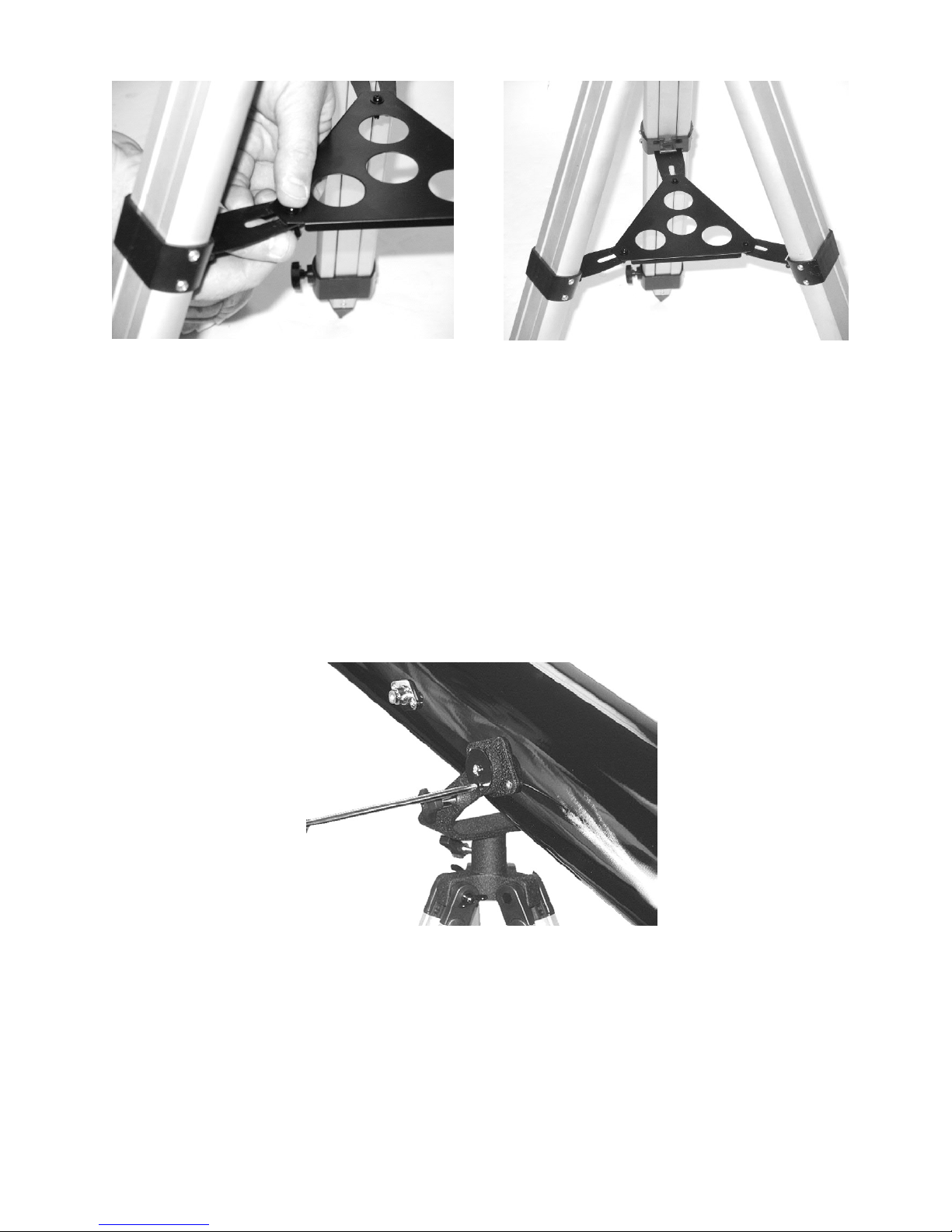
(Fig. 3) (Fig. 4)
5) After the nuts and bolts have been firmly tightened, the telescope optical tube
assembly can be attached to the yoke. On each side of the optical tube there is a round
black metal washer. Each washer has a large screw (altitude locking screw) in the
center and a smaller screw near the outside edge. Loosen all the screws. Mount the
optical tube assembly in the yoke as shown in Fig. 5. Rotate each washer slowly while
gently attempting to tighten the small screw by turning it clockwise with a Phillips (+)
screwdriver. When the washer is correctly oriented the small screw will fit into a hole
beneath the washer. Tighten the small screw firmly. Tighten the two altitude locking
screws. Repeat for the other side. (Note: Some production models may have two small
screws on each side of the optical tube assembly. In this case, tighten both screws
firmly.)
(Fig. 5)
6) Locate the vertical fine adjustment rod. It is a chrome-plated metal rod about six
inches long. Insert the smooth end into the chromed holder located on the side of the
yoke (See Fig. 6). You may have to loosen the large plastic locking knob in order to
insert the chromed rod. Once the rod is inserted (with the end with the hole facing the
focusing assembly) tighten the large locking knob just enough to prevent the rod from
falling out. Locate the chromed post on the side of the telescope tube near the
focusing assembly.
5
 Loading...