

Page 1

THE VOIP MIGRATION COMPANY
TM
EXTender
Guide
TM
IP6000 - Quick Installation
G-IP6000-RUC Rev AC
February 9, 2007
Page 2

Copyright © 2001, 1999-2000, Citel
All Rights Reserved
Printed in USA February 9, 2007
Notice
Every effort was made to ensure that the information in this book was complete and accurate at the time
of printing. However, information is subject to change.
Your Responsibility for Your System’s Security
Toll fraud is the use of your telecommunications system by an unauthorized party, for example, persons
other than your company’s employees, agents, subcontractors, or persons working on your company’s
behalf. Note that there may be a risk of toll fraud associated with your telecommunications system and, if
toll fraud occurs, it can result in substantial additional charges for your telecommunications services.
You and your system manager are responsible for the security of your system, such as programming and
configuring your equipment to prevent unauthorized use. The system manager is also responsible for
reading all installation, instruction, and system administration documents provided with this product in
order to fully understand the features that can introduce risk of toll fraud and the steps that can be taken
to reduce that risk. Citel Technologies does not warrant that this product is immune from or will prevent
unauthorized use of common-carrier telecommunicat ion services or facilities accessed through or
connected to it. Citel Technologies will not be responsible for any charges that result from such
unauthorized use.
EXTender™ IP6000 Quick Installation Guide 2
Page 3
EXTender™ IP6000 Quick Installation Guide 3
Page 4
EXTender™ IP6000 Quick Installation Guide 4
Page 5

Table of Contents
..........................................................................................................................................5 Table of Contents
.......................................................................................7 Regulatory – Compliance and Agency Approval
...........................................................................................................................10 Purpose of this Document
.....................................................................................................................................10 Naming Convention
.................................................................................................................................10 Safety Considerations
................................................................................10 Protection of the Environment – The WEEE Directive
......................................................................................................................10 Support Telephone Numbers
................................................................................................................................................11 Specifications
...............................................................................................................................11 Regulatory Approvals
.................................................................................................................................11 System Architecture
....................................................................................................................................................11 Memory
...............................................................................................................................................11 WAN Ports
.................................................................................................................................................11 Interfaces
........................................................................................................................................................11 Voice
............................................................................................................................11 Protocols and Services
..................................................................................................................................................11 Electrical
.............................................................................................................................................11 Environment
..............................................................................................................................................11 Dimensions
......................................................................................................................................................11 Weight
Prerequisites for Installation........................................................................................................................12
................................................................................................................................12 Network Requirements
.................................................................................13 ISDN Requirements (for asynchronous connections)
....................................................................................................13 Information for the System Administrator
...............................................................................................................................14 Compatible Telephones
..............................................................................................................16 Parts Provided with the EXTender
........................................................................................................16 Parts Not Provided with the EXTender
..........................................................................................................................16 Installation Considerations
........................................................................................................................................17 Typical Installation
.....................................................................................................................17 Mounting the EXTender 6000
.................................................................................................................................................18 Connections
Telephony Wiring (RJ-21)............................................................................................................................19
.................................................................................................................................................20 VT-100 Setup
Power-Up........................................................................................................................................................21
..............................................................................................................................................21 LED States:
......................................................................................................................................22 Basic Configuration
..............................................................................................................................23 Installation Environment
...............................................................................................................24 Synchronous-Serial (RVP_Direct)
................................................................................................................24 Prerequisites for Configuration
.............................................................................................................25 Asynchronous-Serial (RVP_Direct)
................................................................................................................25 Prerequisites for Configuration
.........................................................................................................................27 IP Network (RVP_Over_IP)
................................................................................................................27 Prerequisites for Configuration
..........................................................................................................................27 TCP/UDP Requirements
..................................................................................................................................27 Basic Configuration
.......................................................................................................................27 EXTender Port Bandwidth
.................................................................................................................................................28 Setup Wizard
............................................................................................................................28 Setting the Country Code
..........................................................................28 Standard Console User Interface vs. the Setup Wizard
....................................................................................28 How to access the Setup Wizard through the MI
.........................................................................................................................29 Dial-Up Modem Connection
.................................................................................................30 Installing the Modem at the Remote Site
.......................................................................................................................................31 Telnet Connection
............................................................................................................................................32 HTML Interface
...............................................................................................................................................34 Placing a Call
........................................................................34 Using the digital telephones connected to the EXTender
...............................................................................................34 Placing an 911 Analog Call (if purchased)
.......................................................................................................................34 Lifeline or 911 Phone Notice
EXTender™ IP6000 Quick Installation Guide 5
Page 6

....................................................................................................................35 Remote Telephone Messages
.................................................................................................................................36 Optional Configuration
......................................................................................................................................37 2 to 1 Configuration
..................................................................................................................................................37 RVP_Direct
..............................................................................................................................................39 RVP_Over_IP
..........................................................................................................................40 Setting up the Analog Port
................................................................................................................................................40 Procedure
.........................................................................................41 Setting the Make Set Busy Key (Meridian Only)
................................................................................................................................................41 Procedure
..............................................................................................................................42 Setting up Call-Suspend
................................................................43 Procedure for Avaya and Meridian (EXTender Configuration)
..................................................................44 Procedure for Avaya and Meridian (Gateway Configuration)
....................................................................................46 Procedure for Norstar (EXTender Configuration)
......................................................................................47 Procedure for Norstar (Gateway Configuration)
............................................................................................48 Fax Support on the Second B (Ch 2) Channel
....................................................................................48 Using an MCA Adapter with a Meridian Telephone
EXTender™ IP6000 Quick Installation Guide 6
Page 7

Regulatory – Compliance and Agency Approval
This equipment complies with or has obtained Regulatory Agency approval at least against the following
standards:
EMC – Immunity EN 55024 (1998) + Amendments A1 + A2
Safety EN 60950 (2000)
Telecom – Analog TIA-968-A
Compliance and Regulatory Statements
1. EN55022 and CISPR22 Statement
This is a Class B product.
2. FCC Part 15 Statement
This digital equipment has been tested and found to comply with the limits for a Class B digital device,
pursuant to Part 15 of the FCC Rules.
These limits are designed to provide reasonable protection against harmful interference in a residential
installation. This equipment generates uses and can radiate radio frequency energy and, if not installed
and used in accordance with the instruction manual, may cause harmful interference to radio
communications. However there is no guarantee that interference will not occur in a particular installation.
If this equipment does cause harmful interference to radio or television reception, which can be
determined by turning the equipment off and on, the user is encouraged to try to correct the interference
by one or more of the following measures:
• Reorient or relocate the receiving antenna.
• Increase the separation between the equipment and receiver.
• Connect the equipment into an outlet on a circuit different from that to which the receiver is
connected.
3. FCC Part 68 Statement
Models E-6000Z-RUMxx
Equipped with the optional Analog card, this equipment complies with Part 68 of the FCC Rules and the
requirement adopted by ACTA of the United States.
On the product nameplate of this equipment (located on the bottom of the equipment) is a label that
contains, among other information, a product identifier in the format US: 2DKOT01BEXT6001.
If requested, this number must be provided to the telephone company.
Connection to the Telephone Line
• This equipment uses RJ11C jacks for connection to the telephone line. You must, upon, request,
provide the following information to your local telephone company: USOC Jack type: RJ11C.
• This equipment cannot be used on the public coin phone service provided by the telephone company.
Connection to party line service is subject to state tariffs.
• Your telephone company may discontinue your service if your equipment causes harm to the
telephone network. They will notify you in advance of disconnection, if possible. During notification,
you will be informed of your right to file a complaint to the FCC.
UL 60950-1
CSA C22.2 N° 60950-1
IC CS-03 Part 1
EMC - Emission
EMC - Immunity
Safety
Telecom - Analog
FCC CFR 47 Part 15
EN 55022 (1998) + Amendments A1 + A2
EN 55024 (1998) + Amendments A1 + A2
EN 60950 (2000)
UL 60950-1
CSA C22.2 N° 60950-1
TIA-968-A
IC CS-03 Part 1
TBR21
EXTender™ IP6000 Quick Installation Guide 7
Page 8

• Occasionally, your telephone company may make changes in its facilities, equipment, operation, or
procedures that could affect the operation of your equipment. If so, you will be given advance notice
of the change to give you an opportunity to maintain uninterrupted service.
• THE REGISTRATION NUMBER OF THE SYSTEM MUST BE PROVIDED SO THAT THE
TELEPHONE COMPANY CAN ASCERTAIN INTENDED MODES OF OPERATION AND
VERIFICATION OF REGISTRATION PORT.
If a need arises in the future, the telephone company will call the user and request the following
information for any equipment being connected to the Public Switched Telephone Netwo rk:
Manufacturer: Citel Technologies
Model Number: E-6000Z-RUM08 or E-6000Z-RUM12 Refer to the nameplate on the bottom of
the unit
FCC Registration Number: Refer to the nameplate on the bottom of the unit
Ringer Equivalence Number (REN): 0.9B
Facility Interface Code (FIC): 02LS2
Universal Service Order Code (USOC): RJ11C
Telephone plug(s): RJ11
The Ringer Equivalence Number (REN)
The FCC Registration Label, found on the bottom of the unit, includes the REN. This number is a
representation of the electrical load that will be applied to your telephone line once the unit is plugged into
your wall jack. The telephone line serving your premises will not operate properly if the total ringer load
exceeds the capability of the telephone company central office equipment. That is, if too many ringers (or
their equivalent) are connected to the line, there may be insufficient energy to ring your telephones or
activate other equipment. If the ringer load is excessive, you may also have difficulty dialing telephone
numbers.
Problems, Repair and Warranty
Should you experience trouble with this telephone equipment or for repair or warranty information, please
contact Citel Technologies, at 1-888-454-5828. If the equipment is causing harm to the telephone
network, the telephone company may request that you disconnect this equipment from the line network
until the problem has been corrected.
4. Industry Canada Statements
This digital equipment does not exceed Class B limits for radio noise emissions from digital apparatus, set
out in Radio Interference Regulation of the Industry Canada. Operation in a residential area may cause
unacceptable interference to radio and TV reception requiring the owner or operator to take whatever
steps necessary to correct the interference.
Models E-6000Z-RUMxx
This product meets the applicable Industry Canada technical specifications.
When equipped with the optional Analog card, a Registration Number is printed on the product
nameplate, located on the bottom of this equipment. This certification means that the equipment meets
certain telecommunications network protective, operations, and safety requirements as pres cribed in the
appropriate Terminal Equipment Technical Requirements document(s). The Industry Canada does not
guarantee the equipment will operate to the user's satisfaction.
Before installing this equipment, users should ensure that it is permissible to be connected to the facilities
of the local telecommunications company. The equipment must also be installed using an acceptable
method of connection. The customer should be aware that compliance with the above conditions may not
prevent degradation of service in some situations.
Repairs to certify equipment should be made by a Citel Technologies authorized maintenance facility.
Any repairs or alterations made by the user to this equipment, or equipment malfunctions, may give the
telecommunications company cause to request the user to disconnect the equipment. Users shoul d
EXTender™ IP6000 Quick Installation Guide 8
Page 9

ensure for their own protection that the electrical ground connections of the power utility, telephone lines
and internal metallic water pipe system, if present, are connected together. This precaution may be
particularly important in rural areas.
Users should not attempt to make such connections themselves, but shoul d contact the
appropriate electric inspection authority, or electrician, as appropriate.
The Ringer Equivalence Number (REN)
The Ringer Equivalence Number (REN: 0.4) assigned to each terminal device provides an indication of
the maximum number of terminals allowed to be connected to a telephone interface. The termination on
an interface may consist of any combination of devices subject only to the requirement that the sum of
Ringer Equivalence Numbers of all the devices does not exceed 5.
5. Notice d'Industrie Canada
Cet équipement n’émet pas de bruits radioélectriques dépassant les limites applicables aux appareils
numériques de la classe B prescrites dans le Règlement sur le brouillage radioélectrique établi par
l’Industrie Canada. L'exploitation faite en milieu résidentiel peut entraîner le brouillage des réceptions de
radio et de télévision, ce qui obligerait le propriétaire ou l'opérateur à prendre les dispositions necessaries
pour en éliminer les causes.
Modéles E-6000Z-RUMxx
Le présent matériel est conforme aux spécifications techniques applicables d’Industrie Canada.
Quand la carte Analog est installée, un numéro d’enregistrement est indiqué sur l’étiquette du produit
situé sous l’équipement. Ce numéro d’enregistrement du Canada identifie le matériel homologué. Cette
étiquette certifie que le matériel est conforme aux normes de protection, d'exploitation et de sécurité des
réseaux de télécommunications, comme le prescrivent les documents concernant les exigencies
techniques relatives au matériel terminal. Le Ministère n'assure toutefois pas que le matériel fonctionnera
à la satisfaction de l'utilisateur.
Avant d'installer ce matériel, l'utilisateur doit s'assurer qu'il est permis de le raccorder aux instal lations de
l'entreprise locale de télécommunication. Le matériel doit également être installé en suivant une méthode
acceptée de raccordement. L'abonné ne doit pas oublier qu'il est possible que la conformité aux
conditions énoncées ci-dessus n'empêche pas la dégradation du service dans certaine s situations. Les
réparations de matériel homologué doivent être coordonnées par un représentant dési gné par Citel
Technologies. L'entreprise de télécommunications peut demander à l'utilisateur de déb rancher un
appareil à la suite de réparations ou de modifications effectuées par l'utilisateur ou à cau se d’un mauvais
fonctionnement.
Pour sa propre protection, l'utilisateur doit s'assurer que tous les fils de mise à la terre de la source
d'énergie électrique, des lignes téléphoniques et des canalisations d'eau métalliques, s'il y en a, sont
raccordés ensemble. Cette précaution est particulièrement importante dans les régions rural es.
L'utilisateur ne doit pas tenter de faire les raccordements lui-même, mais doit avoir recours à un
service d’inspection d’installations électriques ou d’un électricie n.
Indice d’équivalence de la sonnerie (IES)
L'indice d'équivalence de la sonnerie (IES : 0.4) assigné à chaque dispositif terminal indique le nombre
maximal de terminaux qui peuvent être raccordés à une interface. La terminaison d'une interface
téléphonique peut consister en une combinaison de quelqu es dispositifs, à la seule condition que la
somme d'indices d'équivalence de la sonnerie de tous les dispositifs n'excède pas 5.
Making Changes or Modifications
Any changes and modifications not expressly approved by Citel Technologies will void any compliance
and regulatory approval, and will void the user’s authority to operate the equipment.
EXTender™ IP6000 Quick Installation Guide 9
Page 10
Purpose of this Document
This document provides the step-by-step process for the complete installation, basic configuration, and
troubleshooting of the EXTender IP6000 (12 port) for Branch Offices.
Please note that the Extender IP6000-RUC has IP connectively only, WAN connection is NOT
supported.
Naming Convention
The EXTender IP6000 is also referred to as the EXTender or the Remote Unit within this document.
Safety Considerations
IMPORTANT SAFETY INSTRUCTIONS
• Do not install this product near water.
Example: In a wet basement location.
• Do not overload wall outlets, as this can result in the risk of fire or electrical shock.
• Do not attach the power supply cord to building surfaces. Do not allow anything to rest on the power
cord. Do not place this product where anyone can step on the cord.
• Do not operate the system if chemical gas leakage is suspected in the area. Use a telephone located
in another, safe area to report the trouble.
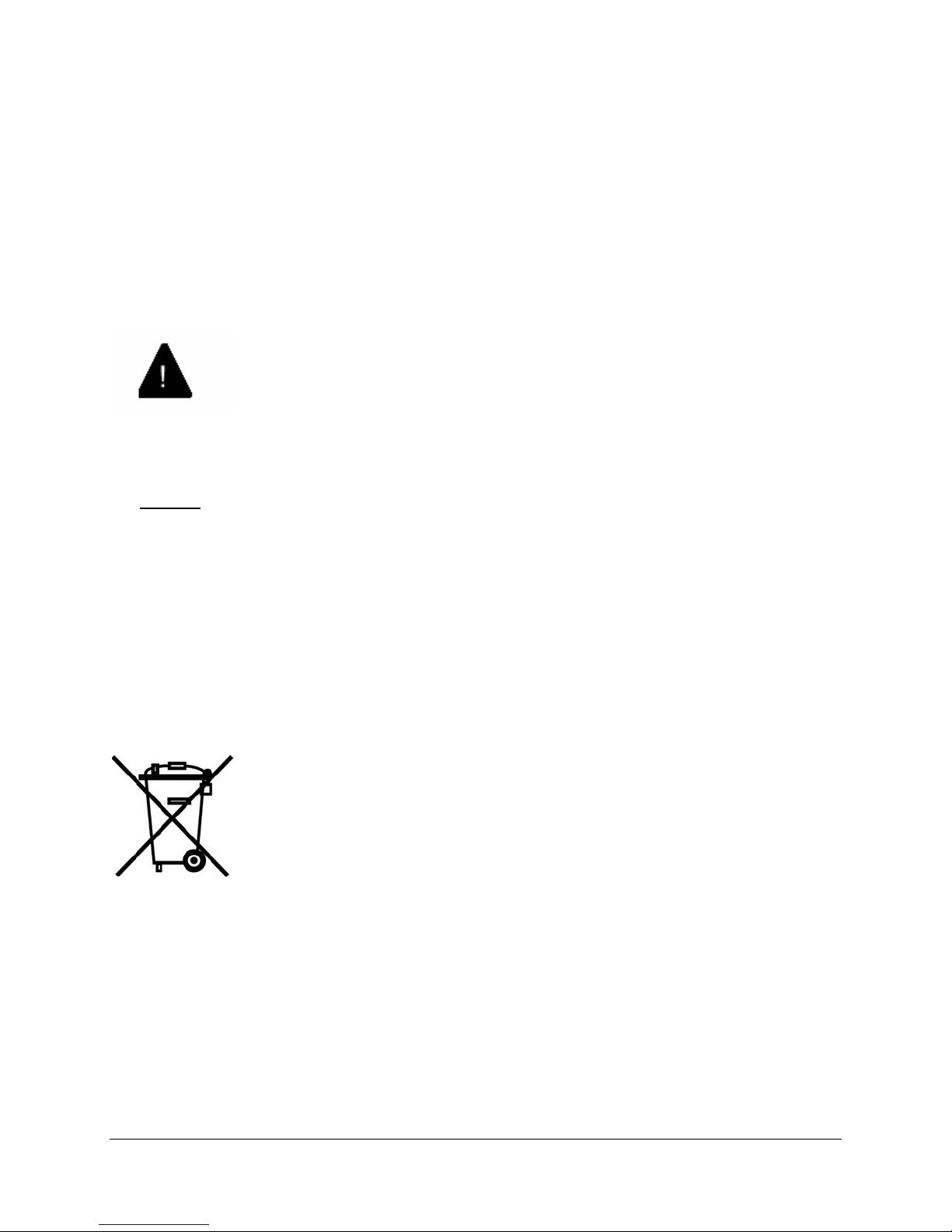
Protection of the Environment – The WEEE Directive
This equipment is marked according to the European directive 2002/96/EC on Waste Electrical and
Electronic Equipment (WEEE). By ensuring this product is disposed of correctly, you will help prevent
potential negative consequences for the environment and human health, which could otherwise be
caused by inappropriate waste handling of this product.
This symbol on this equipment indicates that this appliance may not be treated as
household waste. Instead it shall be handed over to the applicable collection point for
the recycling of Electrical and Electronic Equipment.
Disposal must be carried out in accordance with local environmental regulations for
waste disposal.
For more detailed information about treatment, recovery and recycling of this product
please contact your local city office or your household waste disposal service.
Support Telephone Numbers
For technical problems please contact Customer Support at 1-888-454-5828 betwee n 8:30am - 8:00pm
(EST). If you are outside North America please dial 1-617-454-6192.
NOTE: RemoteConneX is not available in Europe.
EXTender™ IP6000 Quick Installation Guide 10
Page 11

Specifications
Regulatory Approvals
FCC 47 CFR Part 68 US: 2DKOT01BEXT6001; 47 CFR Part 15 Subpart B
CE EN55024+A1, A2; EN55022+A1, A2; EN6100-3-2; EN6100-3-3
Industry Canada CS-03; 3807B-EXT6001
Safety UL60950-1; C22-2 Nº60950-1; EN60950-1; IEC60950-1
System Architecture
CPU Motorola MPC 852T, 50 MHz
DSP 5 Analog Devices 2185 75 MIPS per Device
Memory
DRAM 16MB
Flash Memory 8MB
WAN Ports
Protocol Synchronous-serial; Asynchronous-serial
Interface RS-232, V.35, or RS-530
Encapsulation High-level Data Link Control (HDLC)
Interfaces
Ethernet Single 10 / 100 megabit, RJ-45
Serial/WAN EIA/TIA-232, EIA/TIA-530, EIA/TIA-V35
Management Serial RS-232, DB9
PBX/KSU Up to 8 digital line interfaces over a 25 pair RJ-21 cable
Voice
Voice compression G.729a, G.711, G.726 (ADPCM 32 and ADPCM 24
Protocols and Services
LAN RVP over Internet Protocol (IP)
WAN Remote Voice Protocol (RVP™) (proprietary) over HDLC
Electrical
Line Voltage 100-240 VAC
Frequency 50-60 Hz
Max Power
Consumption
Protection Over Current/Voltage and short circuit protection
Environment
Temperature 32° - 130° F (0° - 55° C)
Relative Humidity 5 to 95%
Dimensions
17 in x 8 in 1 3/4 in (432 mm x 203 mm x 44 mm)
Weight
6 lbs 7 oz (3 kg)
60 W
EXTender™ IP6000 Quick Installation Guide 11
Page 12
Prerequisites for Installation
You must meet the following requirements before installing the EXTender 6000:
Network Requirements
• You must install and configure appropriate network terminating devices at both the corporate facility
and the branch office. Both network-terminating devices must be fully functional and both must
support an RS-232, V.35, or RS-530 synchronous, asynchronous or Voice over IP (VOIP) interface.
• If you use an asynchronous connection, you must install the appropriate ISDN Terminal Adapters
(TAs), from the list below. The TAs must be operational at both the corporate facility and the Branch
Office. This list is complete as of the release date of this document. Refer to the Citel’s Web site:
[email protected] for the most recent list of recommended ISDN TAs.
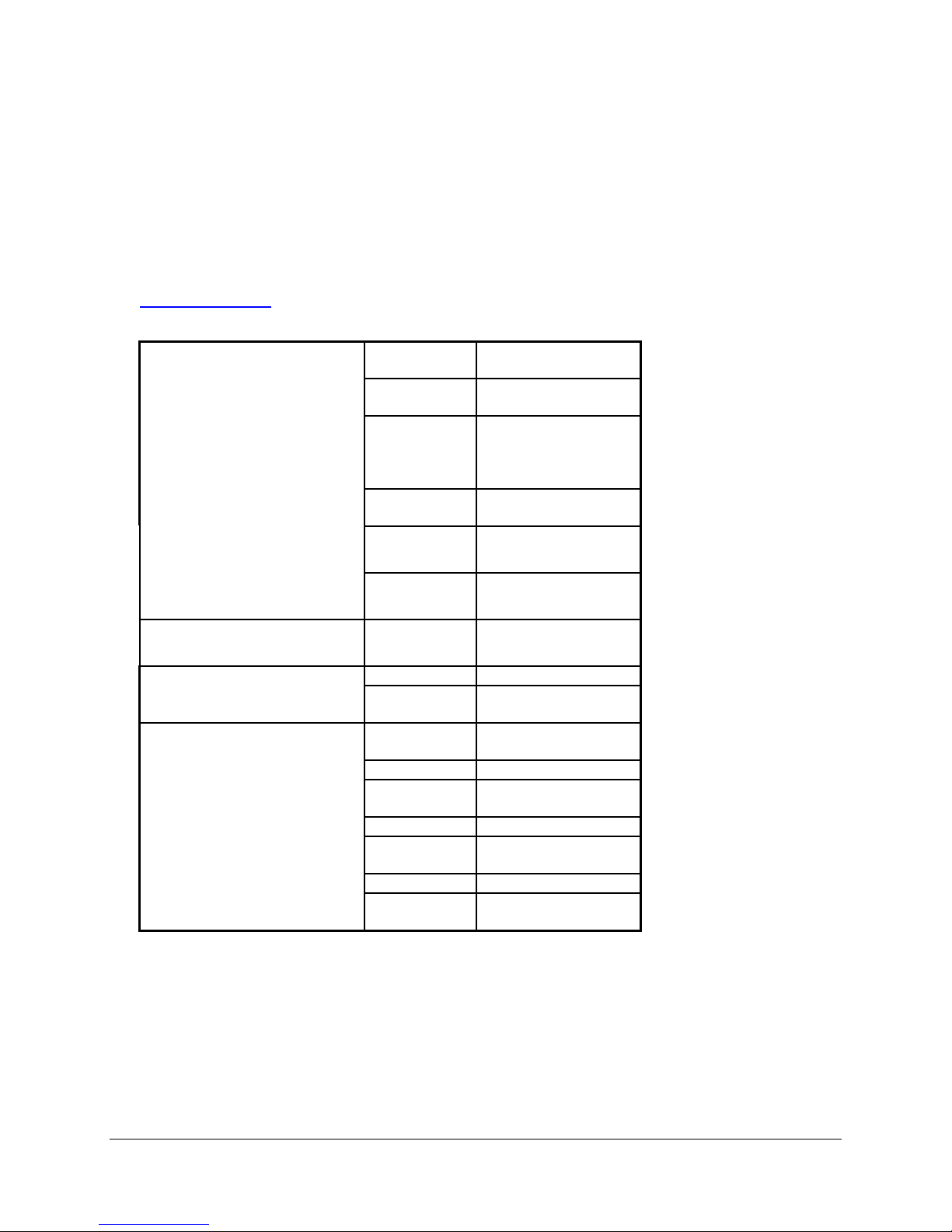
Table 1: ISDN TAs
TA’s (for Async)
--
TA’s (for Sync 128k
bonding)
CSU/DSU’s
* European Use
Note: For the Async-RS 232 Dial feature to work properly for these devices, you must set up each device
to accept incoming “AT Commands”. Consult the documentation provided with each device for
proper instructions.
Provide proper wiring with adequate punchdown blocks to connect the Remote Unit to the telephones.
Follow the details in
Pin Out Assignments on page 19, and provide an RJ-21 female connector.
MFG Model(s)
(see note)
Motorola Bitsurfr Pro
Bitsurfr Pro EZ
Adtran ISU 128 (see note)
ISU 2X64
Express 3000
Express NTU
3Com ISDN TA
3Com U.S Robotics
*Connect IQ 400 Series
*Multitech LWAY Hopper
(Async Only)
NA <Manual_SETUP_1>
<Manual_SETUP_2>
Motorola Bitsurfr Pro
Adtran ISU 128 (see note)
ISU 2X64
Paradyne Acculink 3165
7110 SNMP
Adtran TSU LT
General
DataComm
RAD FCD-1L
ADC Kentrox DataSmart Max
Motorola FT100S
Larscom
Orion
DeskTop 554A
72761, 78640
56/T1
EXTender™ IP6000 Quick Installation Guide 12
Page 13

ISDN Requirements (for asynchronous connections)
Before you install your units, order an ISDN BRI line at both the local site and the remote branch office.
This ISDN line should be capable of the following:
• The ability to make two “data” calls, one on each B Channel of the ISDN line.
• If long distance, both “data” calls must be set up as “data”.
Note: Confirm this with your long distance provider when you order your ISDN Line. A call is defined
as “voice” or “data” in the setup message.
Information for the System Administrator
Once your ISDN line is installed, you will be provided with two Service Profile Identifiers (SPIDs) and also
two Directory Numbers (DNs). These numbers must be provided to the System Administrator.
Note: Make sure you write down the SPIDs and DNs, and keep this in a safe place for reference when
installing the ISDN Terminal Adapters. If you do not have the SPIDs or DNs, you will not be able to
program the ISDN Terminal Adapters.
EXTender™ IP6000 Quick Installation Guide 13
Page 14

Compatible Telephones
Nortel (Meridian and Norstar) Avaya
Meridian
M2006 *
M2008 *
M2216
M2250 6408+
M2317 6416D+
M2616 6424D+
M2616CT 8403
M3110 8405
M3901 8410D
M3902 8411D
M3903 8410DR
M3904 8434DX
M3905 9040 TransTalk
9410
Norstar
M7100 *
M7208**
M7310
M7324
M7410
ATA2
T7316
T7316E
T7208**
* This digital display telephone is NOT
recommended for administrative purposes.
** Recommended if a set must be extended via the
ConneX port.
2402
2410
2420
6402+ *
CallMaster III
CallMaster IV
CallMaster V
CallMaster VI
Gray Market
9031DCP
XM24 (add-on module for 64xx)
* This digital display telephone is NOT recommended
for administrative purposes.
Toshiba Magix Digital Telephones
DKT2004 4424LD+
DKT2010 4424D+
DKT2020 4412D+
Compatible Voice System:
Toshiba Strata DK
4406D+
4400D
DSS 4450 (add on module for 4424LD+ and
4424D+)
4400
Compatible Voice System:
Avaya™ MERLIN MAGIX®
Alcatel Ericsson
Reflexes 4023 Dialog 3200
Reflexes 4034 Dialog 3201
Reflexes 4035 Dialog 3202
Dialog 3203
Compatible Voice System: Dialog 3210
Alcatel 4400 Dialog 3211
Alcatel 4200 Dialog 3212
Dialog 3213
DBY 409 – Add on Module Key for Dialog 3213
Compatible Voice System:
Ericsson MD 110
EXTender™ IP6000 Quick Installation Guide 14
Page 15

Compatible Telephones, continued
Panasonic DBS Iwatsu
44210 IX-MKT
44220 IX-12KTD-2
44223 IX-24KTD-2
44224 IX-12KTD-3
44225 IX-24KTD-3
44230
44233 Compatible Voice System:
Compatible Voice System:
Panasonic DBS 576
Panasonic DBS 576 HD
Avaya IP Office (PBX Type to Select)*
4406D+ (Magix)
4412D+ (Magix)
4424D+ (Magix)
DSS 4450 (add on module for 4424LD+ and
4424D+)
2402 (Definity)
2410 (Definity)
2420 (Definity)
6408+ (Definity)
6416D+ (Definity)
6424D+ (Definity)
5402 (Definity)
5420 (Definity)
XM24 (add-on module for 64xx)
Iwatsu ADIX APS
NOTE: To select the proper PBX type go to the Utilities menu in the UI and run the Setup Wizard.
EXTender™ IP6000 Quick Installation Guide 15
Page 16

Parts Provided with the EXTender
Table 2: Part Provided with the EXTender
Quantity Description
1 EXTender IP6000
1 Power Cord
1 DB-25, RS-530 cable
1 DB-9 RS-232 cable
Cat 5 Ethernet Cable 1
- Mounting Hardware
2 Mounting Brackets
1 Quick Install Guide
Parts Not Provided with the EXTender
• Digital telephones and communication line cords are NOT supplied with this system.
Note: Use two-wire digital telephones only.
• Punchdown blocks necessary to interface between the RJ-21 connector and the remote telephones.
• 50 pin cable with male RJ-21 connectors to interface between the punchdown block and the
EXTender. (See
• Analog telephone line for local use, if you purchased an analog line card.
Note: The analog line card is not available outside North America.
Pin Out Assignments on page 19)
Installation Considerations
• The system operates from 100-240 VAC, 50-60 Hz. Do not apply power to the unit until instructed to
in the installation procedures.
• Install the power supply and cabling away from high power/high RF noise devices such as computers,
fans, fluorescent ballast, or power supplies.
• Use good wiring practices. Do not run wires over fluorescent lights, computers, air conditioners, etc.,
as this can introduce noise to the modems.
• The distance from the telephones to the EXTender should NOT exceed 500 feet.
EXTender™ IP6000 Quick Installation Guide 16
Page 17
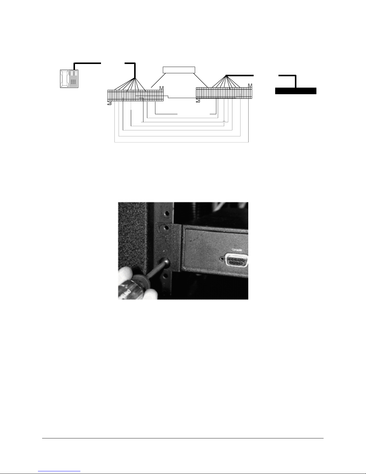
Typical Installation
The figure below shows a typical installation of the EXTender.
RJ-21
(up to 12 Ports
per unit)
Figure 1: Typical 6000 Installation
Mounting the EXTender IP6000
You can mount the EXTender in a standard 19-inch communication rack using the brackets provided or
simply place it on a shelf within the rack.
Punch Blocks
Cross-Connect
Wires
RJ-21
(up to 12 Ports)
EXTender 6000
EXTender™ IP6000 Quick Installation Guide 17
Figure 2: Securing the Unit to a Rack
Page 18
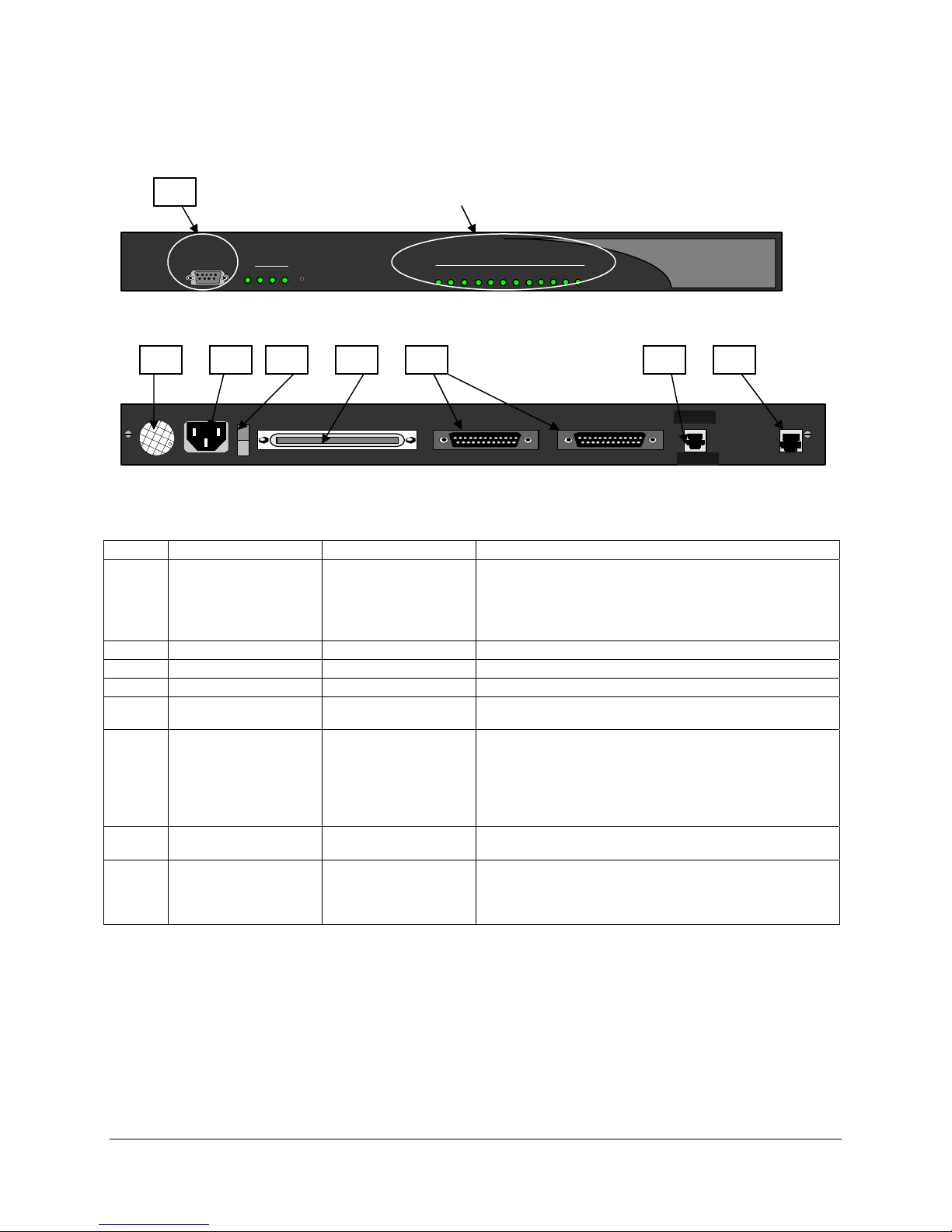
Connections
A
The following figures show the required EXTender connections, A through C.
Note: Connection “F” is for synchronous or asynchronous-serial only; “H” is for connection to an analog
line; and connection “G” is for VOIP.
Console
WAN
PWR 1 32
Reset
Figure 3: Front of EXTender 6000
B C D E F G H
Connected Ports (solid green)
Port Status
31 2 8 9 10 11 127654
LNK
CLN
100-240 V ~ 0.8A 50-60 HZ
TELEPHONY INTERFACE
WAN 1
Figure 4: Back of EXTender 6000
Table 3: EXTender Connections
Letter Label Cable Type Description
Console DB-9 Connect to a PC COM port
A
Fan - Cools unit.
B
Power - Connect to a 120 VAC outlet
C
Power Switch - Turns unit on and off.
D
Telephony Interface RJ-21 Wire to a punchdown block and then to the PBX. (See
E
WAN1 DB-25, serial.
F
WAN2
LAN RJ-45 Ethernet
G
Analog RJ-11 Connects to an analog line for local dialing.
H
straight-through
Note: Set the COM port as follows: Baud rate: 9600,
Databits: 8, Parity: none, Stopbits: 1, Software flow
control: Xon/Xoff.
Pin Out Assignments on page 19)
Connects the EXTender to a synchronous or
asynchronous- serial device (CSU/DSU or other
network device).
Note: Use an RS-530 type cable or DB-25 to M34 cable
should for high-speed links to V.35 equipment.
Connects the EXTender to the LAN for use in VOIP
applications.
Note: This port does not provide PBX functionality or
features.
WAN 2
LNK ACT
ANALOG LAN
LNK
CLN
0
LAN
EXTender™ IP6000 Quick Installation Guide 18
Page 19
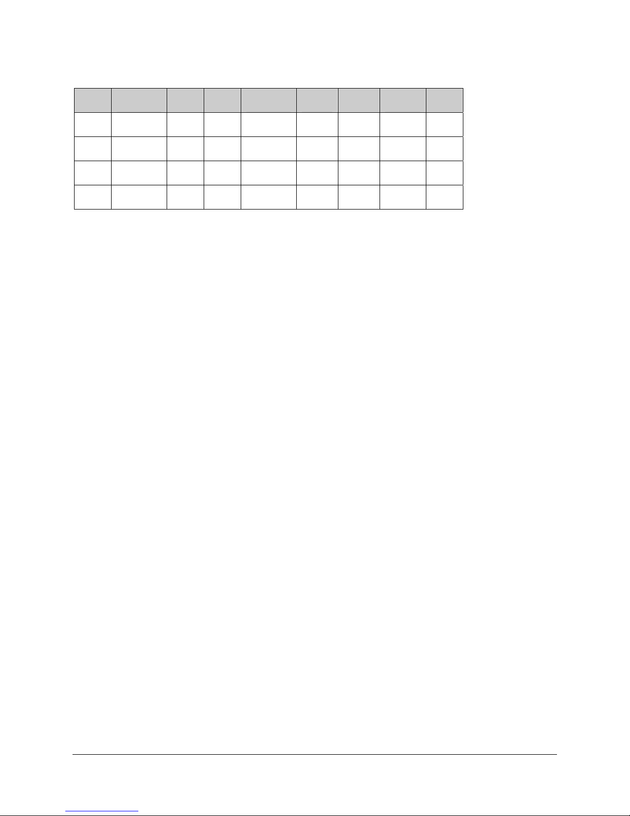
Telephony Wiring (RJ-21)
Table 4: Pin Out Assignments
Pin Cable
Pair
26 WH/BL 1 34 RD/BR 5 42 YL/OR 9
1 BL/WH 9 BR/RD 17 OR/YL
28 WH/GN 2 36 BK/BL 6 44 YL/BR 10
3 GN/WH 11 BL/BK 19 BR/YL
30 WH/SL 3 38 BK/GN 7 46 VI/BL 11
5 SL/WH 13 GN/BK 21 BL/VI
32 RD/OR 4 40 BK/SL 8 48 VI/GN 12
7 OR/RD 15 SL/BK 23 GN/VI
Wire Color Abbreviations:
BK=Black BR=Brown RD=Red OR=Orange SL=Slate
YL=Yellow GN-Breen BL-Blue VI-Violet WH=White
Port Pin Cable
Pair
Port
Pin Cable Port
Pair
EXTender™ IP6000 Quick Installation Guide 19
Page 20
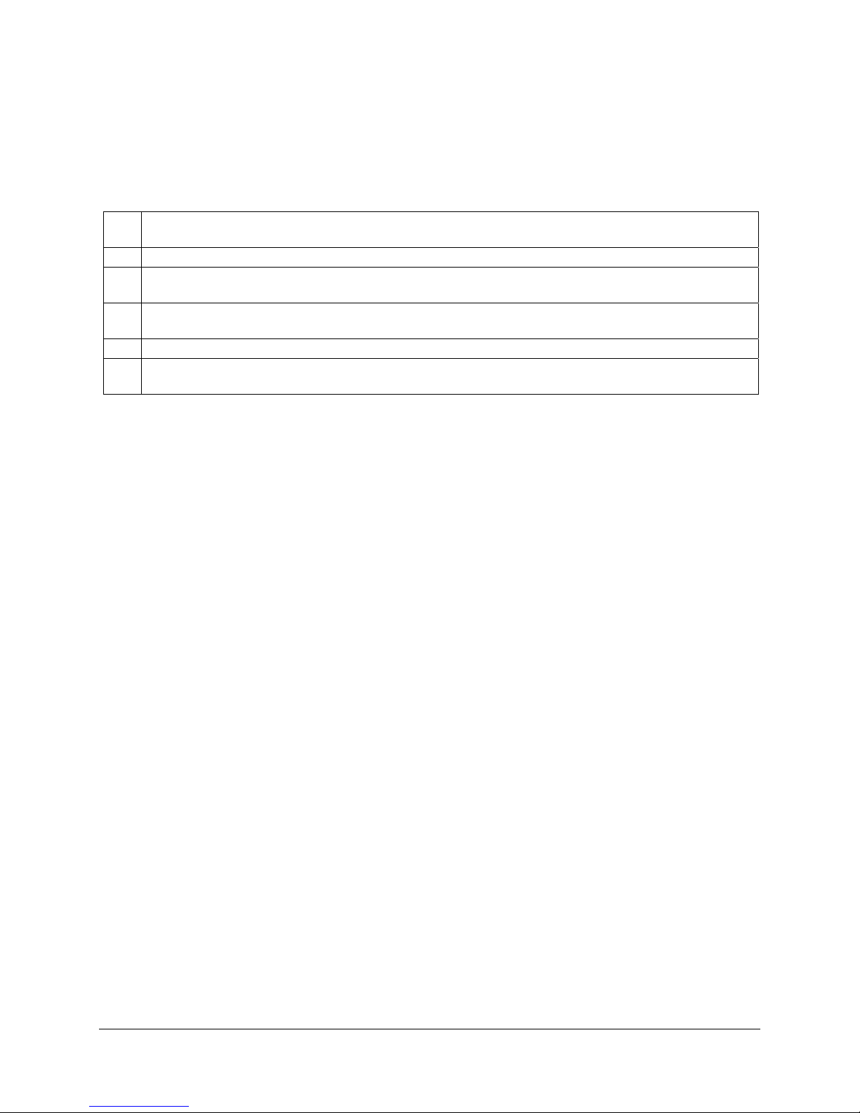
VT-100 Setup
1. Make sure the EXTender is connected as shown on page 17.
2. You must use communications software — for example, HyperTerminal — to configure and test the
EXTender. Attach one end of the RS-232 cable to your PC COM port and the other end to the DB-9
Console port connector on the front of the EXTender.
3. Set up HyperTerminal as follows:
A
Access: Start button > Programs > Accessories >Communications > HyperTerminal folder >
HyperTerminal icon.
B
When prompted for a name, type gateway and click OK.
C
(Determine what port [n] you will connect to on your pxc. At the Telephone Number dialog, select
Connect using = Direct to COMn (ignore other settings) and click OK.
D
At the COMn 1 Properties dialog, set the parameters to 9600, 8, none, 1 and Xon/Xoff and click
OK.
E
When the HyperTerminal window appears, it is blank; that is, there is no logon prompt.
F
Click on File, then Properties. Select Settings tab and go to Emulation window. Select VT100
and click OK.
1
n is the number of the COM port on the PC.
4. Go to Power-Up sequence on the next page.
EXTender™ IP6000 Quick Installation Guide 20
Page 21
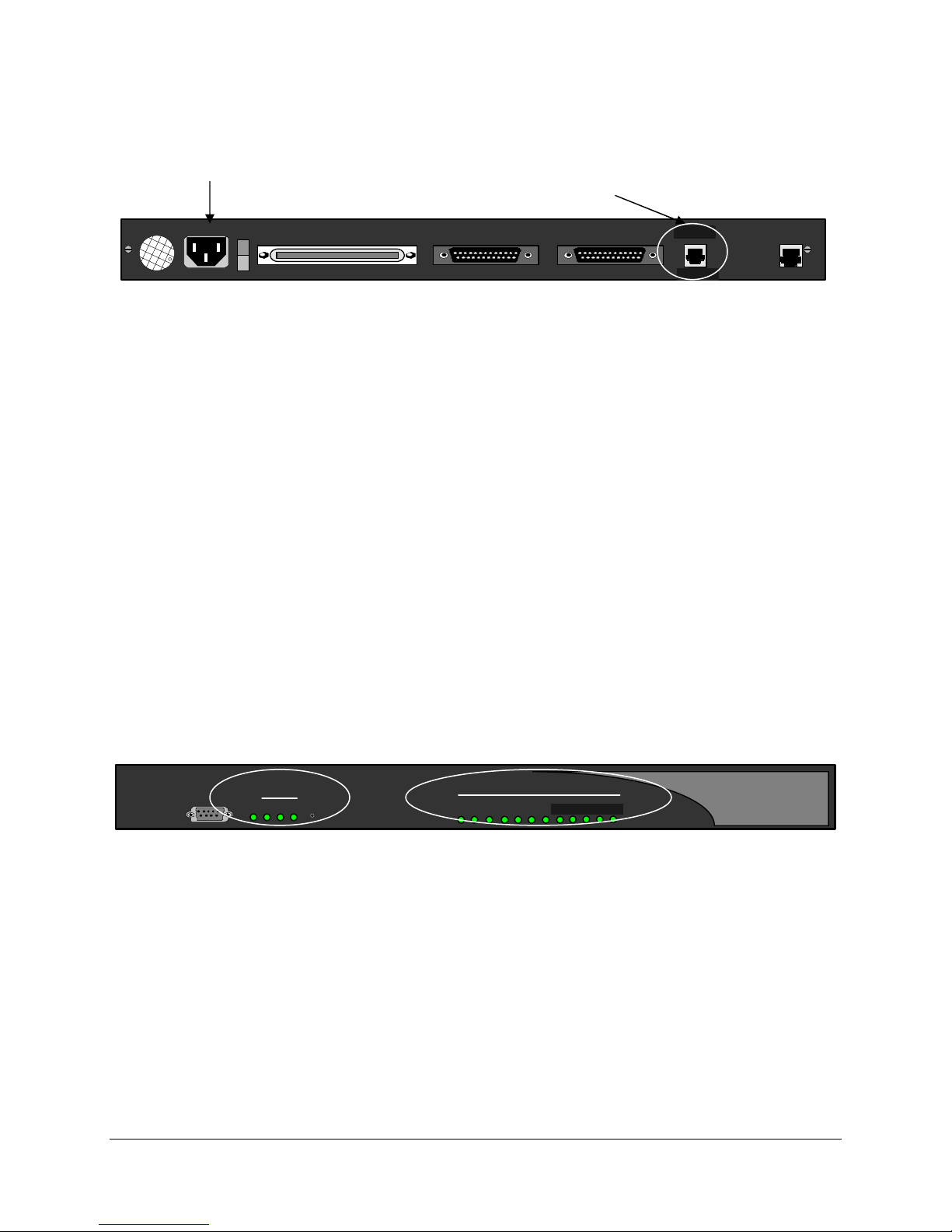
Power-Up
Once the VT-100 program is set up, plug the unit into an AC outlet. The device begins a series of selfdiagnostic tests, which are displayed as a series of LED flashes.
AC Power
LAN
Connection
100-240 V ~ 0.8A 50-60 HZ
TELEPHONY INTERFACE
WAN 1
WAN 2
LNK ACT
ANALOG LAN
LNK
CLN
0
LAN
Figure 5: Back of Unit (LAN Connections)
LAN Notes:
If you are connecting an Extender to an IP network, the unit requires an IP address. The Ethernet port on
the Remote Unit operates on 10 and 100 megabit Ethernet networks. On power-up, if the Ethernet cable
is connected to a network device the Remote Unit will auto-detect whether the network is using 10 or 100
megabit Ethernet. If the network cable is not connected the Remote Unit will default to using 10 megabit
Ethernet. In this case you will need to either manually configure the Ethernet mode to force 10 or 100
megabit Ethernet or power-cycle the Remote Unit with the network cable connected in order to autodetect the 100 megabit Ethernet connection.
Once the power-up sequence is finished, the state of the following LEDs should be Green.
LED States:
PWR
WAN1
Solid Green.
Solid Green (Ready) if a synchronous device is connected to WAN 1.
Solid Orange (Ready) if an asynchronous ISDN TA is connected and accepting
Port LEDs
commands (but there is no link up- in Call Suspend mode or has not dialed it yet).
Solid Green if connected properly to the PBX.
IMPORTANT: If any of the LEDs DO NOT power as explained, refer to the System Administrator’s
Guide for troubleshooting information.
PWR and WAN 1 Connected Ports
Console
WAN
PWR 1 32
Reset
Port Status
31 2 7654
Figure 6: Front of Unit
8 9 10 11 12
LNK
CLN
On initial power-up (or before the config file is changed) the Management Interface (MI) asks you to run
the “Setup Wizard”.
EXTender™ IP6000 Quick Installation Guide 21
Page 22
• If you type “Yes ”, the wizard asks a series of configuration questions. (See page
• If you type “No”, the PC displays the following message:
Press “Enter” to start the EXTender shell…..
IMPORTANT: We recommend that you run the setup wizard on initial power-up as the PBX Type needs
to be set before the unit will become operational, and the phones to initialize. This item can be accessed
at anytime by selecting:
Remote → Utilities → Setup Wizard
Gateway→ Utilities → Setup Wizard
Note: If the EXTender is powered up prior to opening the terminal program, this message does not
appear.
Go to Basic Configuration on the next page.
28.)
Basic Configuration
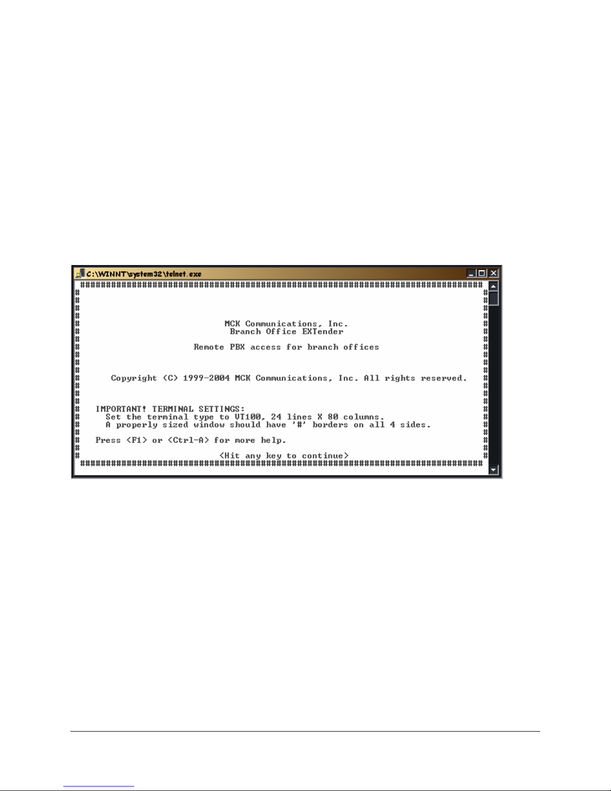
Press Enter. The MI Welcome Screen is displayed.
Figure 7: Welcome Screen
IMPORTANT TERMINAL SETTINGS
The MI requires a screen size of 24 lines X 80 columns. Make sure the Welcome Screen is bordered on
all four sides with a # symbol, as shown in the figure above.
To enlarge the screen (within the VT-100 application)
1. Click any corner of the screen.
2. Drag the screen to enlarge.
3. Check that the screen is bordered by “#” symbols.
Press any key to continue. The Main Menu is displayed.
If you are already familiar with using the MI, proceed to page
for the different Network Environments.
Or……..
Press F1 for the MI Help Screen, which provides basic information for navigating through the interface.
EXTender™ IP6000 Quick Installation Guide 22
23 for information on setting the parameters
Page 23

Installation Environment
This section provides the necessary information to configure the EXTender using the MI. The units are
programmed at the factory with “default” settings providing basic parameters to accommodate most
network environments.
Which type of
Network
Device do you
have?
Table 5: Network Devices
To configure the EXTender with....... See page...
a Synchronous -serial device via WAN Port(s) 1 or 2 (RVP_Direct) using one of the
following protocols:
• V. 35
• RS-232
• RS-530
an Asynchronous -serial device via WAN Port(s) 1 or 2 (RVP_Direct) using RS-232
Protocol.
an IP device – via Ethernet port (RVP_IP). 27
* IP-based products utilize VOIP technology to deliver remote voice solutions. The
voice quality of these solutions is dependent on variables such as available bandwidth,
network latency and quality of service (QoS) initiatives, all of which are controlled by
the network and internet service providers. Because these variables are not our
control, we cannot guarantee the performance of the user’s IP-based remote voice
solution.
Before beginning the configuration process, identify the network device type that is
connected to the EXTender. Once you know the connection type, use Figure 5:
of Unit (LAN Connections)
configuration.
, to determine the appropriate checklist to use for
Back
24
25
EXTender™ IP6000 Quick Installation Guide 23
Page 24
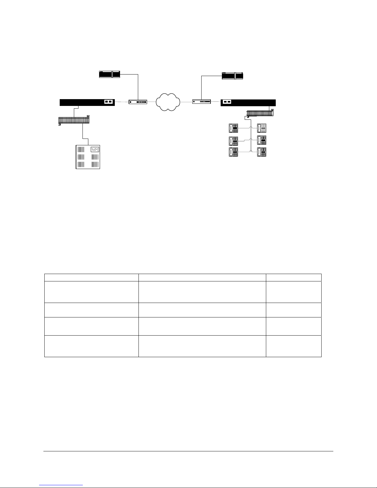
Synchronous-Serial (RVP_Direct)
This section of the manual provides the necessary information to configure the EXTender for connection
to a synchronous-serial device. The units are programmed at the factory with “default” settings providing
basic parameters to accommodate many network environments.
PBXgateway
Punch Block
Corporate Office
PBX
Router
DSU/CSU
Public
DSU/CSU
Router
EXTender IP6000
Punch Block
Branch Office
Figure 8: RVP_Direct Typical Installation
Prerequisites for Configuration
• The Gateway (at the corporate site) and the EXTender (at the branch office) must be installed
properly and the network link between both devices must be operational.
• The network administrator must assign an IP address for both units if you plan to configure and test
them over a LAN or WAN.
Table 6: RVP_Direct Configuration Steps
You must...... To...... Default Setting
Set Connect Parameters 1. Select network type RVP_Direct
2. Identify the Primary Interface WAN_1
3. Set Utilization. 100
Enable/Disable WAN ports Enable WAN ports to connect to network
WAN 1 - Enabled
device.
Set the Sync Rate of the WAN
port
Set the mode (interface type) of
the WAN port. (v.35, RS-232,
Match the data rate (sync rate) of the
network device
Match the interface type of the network
device.
512,000 kbps
V.35
RS-530)
EXTender™ IP6000 Quick Installation Guide 24
Page 25
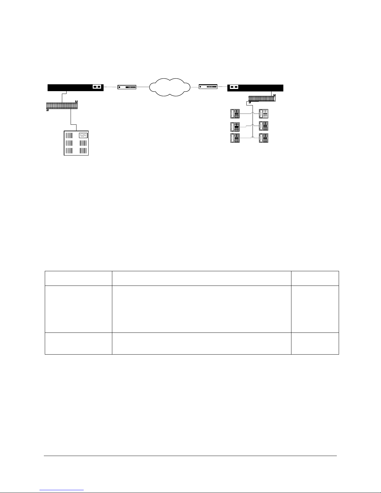
Asynchronous-Serial (RVP_Direct)
This section of the manual provides the necessary information to configure the EXTender for connection
to an asynchronous-serial device. The units are programmed at the factory with “default” settings
providing basic parameters to accommodate many network environments.
PBXgateway
Punch Block
ISDN TA
ISDN
ISDN TA
EXTender IP6000
Punch Block
PBX
Corporate Office
Branch Office
Figure 9: RVP_Direct Async Connections
Prerequisites for Configuration
• Both the Gateway and Remote units must be installed properly and the network link between both
devices must be operational.
• The network administrator must assign IP address information for both Gateway and Remote units.
• The network administrator must provide the remote users with User ID’s and Connect Passwords (if
assigned).
Table 7: Basic Configuration
You must…. To…. Default
Setting
Set the Primary Dial
Numbers (DNs)
Set the mode
(interface type) of the
Identify the first and second ISDN B-channels at the Gateway
unit.
The “Primary Dial Nums 1” is the Directory Number (DN) assigned to
the first B-channel of the ISDN line connected at the Gateway unit.
The “Primary Dial Nums 2” is the Directory Number (DN) assigned to
the second B-channel of the ISDN line connected at the Gateway
unit. Dial these telephone numbers to connect to the Gateway.
Match the interface type of the network device. Set to AsyncRS-232-Dial.
-
V.35
WAN port.
EXTender™ IP6000 Quick Installation Guide 25
Page 26
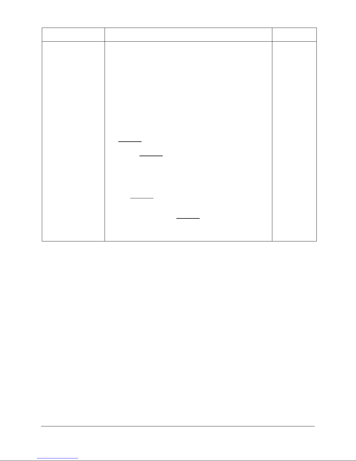
Table 7: Basic Configuration, continued
You must…. To…. Default
Setting
Set the Async
parameters for the
selected WAN port
Match the settings for the device being used.
DCE Type: Select the ISDN TA being used. (See page 12 for
a list of recommended devices.)
Async Rate: Set the asynchronous data transfer speed of the
WAN port, it MUST match the TA speed setting.
ISDN Switch Type: Select the type of Central Office (CO)
-
115200
National_ISDN
switch being used for the ISDN connection.
Phone Numbers: Your System Administrator provides this
information.
• Local Dialing Num1: Enter the DN 1 number assigned to the
ISDN line, which was provided when the ISDN line was installed.
Example: 2881918
•
ISDN SPID 1: Enter SPID 1 assigned to the first ISDN B-
channel.
•
Local Dialing Num2: Enter the DN 2 number assigned to the
ISDN line.
• ISDN SPID 2: Enter SPID 2 assigned to the second ISDN B-
channel.
• Dial Prefix: Enter the required prefix for dialing out on this WAN
port.
Dialback Num1: Enter the telephone number for dialing the first
•
ISDN B-channel of the EXTender from the PBX location where
the Gateway is installed. Example: 914032881918
Example: 40328819180101
Example: 98
• Dialback Num2: Enter the telephone number for dialing the
second ISDN B-channel of the EXTender from the PBX location
where the Gateway is installed.
EXTender™ IP6000 Quick Installation Guide 26
Page 27
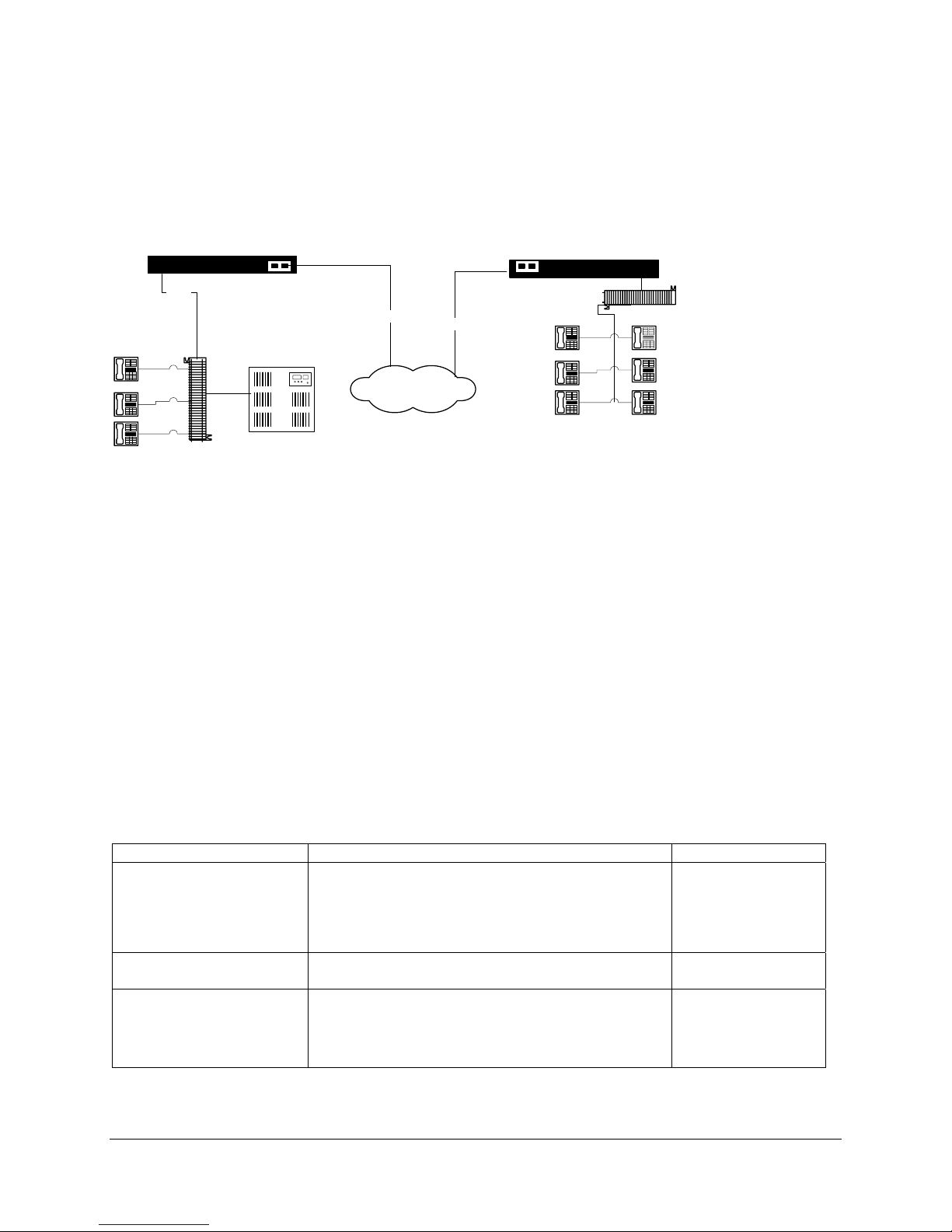
IP Network (RVP_Over_IP)
This section of the manual provides the necessary information to configure the EXTender for connection
within an IP network.
Note: The units are programmed at the factory with RVP_Direct “default” settings. The Type parameter
must be set to RVP_Over_IP.
Corporate Office
PBXgateway
RJ21
PBX
Punch Block
Prerequisites for Configuration
Ethernet
IP Network
Ethernet
Figure 10: RVP_IP Typical Installation
Branch Office
EXTender IP6000
Punch Block
• Both EXTender and Gateway must be installed properly and the network link between both devices
must be operational.
• The network administrator must assign IP address information for both Gateway and Remote units.
• The network administrator must provide the remote users with User ID’s and Connect Passwords (if
assigned).
TCP/UDP Requirements
Ensure that the correct TCP/UDP ports have been opened to allow the EXTender to connect to the
Gateway through your company firewall. The following TCP/UDP port requirements must be met:
The EXTender 6000 uses even numbered ports 12,288 to 12,544. The port numbers start at 12,288 and
increment by 2 to the total number of ports used. For example, if you have an 8 port EXTender 6000 with
3 telephones connected, ensure that ports 12,288, 12,290, and 12,292 are opened.
The Gateway unit uses TCP/UDP port 2698.
Basic Configuration
Table 8: RVP_IP Basic Configuration Steps
You must … to… Default Settings
Set Connect Parameters. Type: RVP_Over_IP RVP_Direct
IP Destination: Enter the IP address of the
Gateway.
EXTender Port Bandwidth
Set the Utilization:
Disable WAN ports Disable WAN ports that are unnecessary for
RVP_IP.
Set IP parameters;
9 IP Address
Allow the Gateway to communicate over the IP
network.
WAN 1 – Enabled
WAN 2 -Disabled
-
10000000
100
-
9 Subnet
9 Default Router
EXTender™ IP6000 Quick Installation Guide 27
Page 28
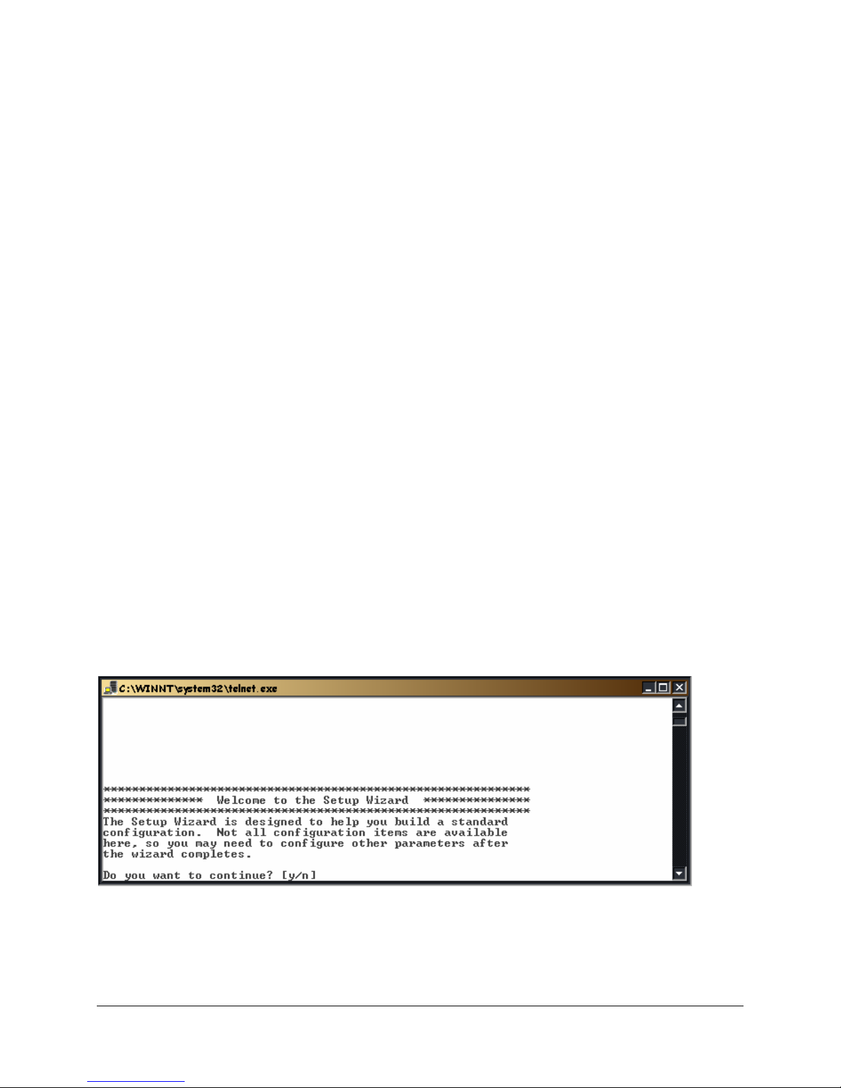
Setup Wizard
IMPORTANT 1: We recommend that you run the setup wizard on initial power-up as the PBX Type
needs to be set before the unit will become operational, and the phones to initialized. This item can be
accessed at anytime by selecting:
Remote → Utilities → Setup Wizard
Gateway→ Utilities → Setup Wizard
Setting the Country Code
The country code is used to set a number of region-specific telephony settings in the system including the
operating characteristics for the local Analog Port. It is important to set the region code correctly before
using the Analog Port feature.
When running the setup wizard you will be prompted to change or set the country code. If you don't know
your country code you can enter ? to display a list of supported countries.
1. Enter the corresponding number and press Enter. You will then be prompted to confirm the correct
country name.
2. Enter Y if the country is correct or N if incorrect. If multiple countries use the same country code the
select N when prompted to confirm will cause the system to display these additional country names
for selection. Select Y when the correct country name is displayed.
The EXTender provides a console setup wizard that guides you through many of the required
programming/ configuration required to complete initial setup of the units, via the VT100 management
console accessed through the DB9 management port.
You can access the setup wizard through the console MI. This requires a P C co nnection to the unit via
the DB9 console port. The wizard requests basics configuration information to establish the initial
configuration programming. You can use the MI to configure parameters that are not configurable throu gh
the wizard.
Standard Console User Interface vs. the Setup Wizard
When a unit is first powered up it checks a Setup Wizard flag. If the flag is set, the standard console UI is
displayed. If the flag is not set, the system prompts you to run the Setup Wizard. After this initial Setup
Wizard prompt, the system sets the Setup Wizard flag to prevent you from receiving this prompt again.
You can access the Setup Wizard through the console MI, if you want to run it later.
How to access the Setup Wizard through the MI
Path: Remote->Utilities->Setup Wizard
EXTender™ IP6000 Quick Installation Guide 28
Figure 11: Set Up Wizard
Page 29
Dial-Up Modem Connection
The Management Interface includes Z Modem functionality for the DB9 dial-up management console port.
An external modem attached to the DB9 port (not included with unit) will be required to dial into the
management console interface of the EXTender. This console interface will allow remote dial-up access
using Z modem protocol to the management console.
Additionally, when a dial-up connection has been established to the management interface of one unit, it
will be possible to then “Rlogin” to other connected units in order to access the management interface of
those units.
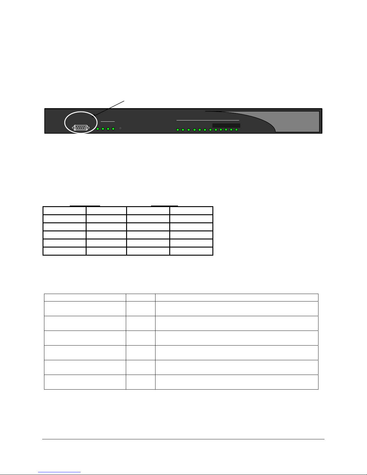
Console
Parts you need for installation
• Modem (not included with unit)
• Direct analog phone line for connection to the modem
• RS-232, DB25 to DB9 modem cable [male-male] (see table below for pinout information)
• Properly installed PBXgateway unit.
DB25 Male DB9 Male
Pin Function Pin Function
2 Tx 2 Rx
3 Rx 3 Tx
7 Common 5 Common
8 DCD 7 RTS
20 DTR 8 CTS
Setting the Modem DIP switches
The modem has a DIP switch located on the outside of the unit. This switch controls modem functionality
and must be set to the guidelines specific below prior to installing the modem.
Function Setting Description
DTR Normal mode ON Computer must provide DTR signal for modem to accept
Verbal result codes ON Display result codes OFF No echo on offline
commands
Auto answer ON ON Modem answers on first ring, or higher.
Carrier Detect (CD) normal ON Modem sends CD signal when it connects with another
DB-9 Console Port
WAN
PWR 1 32
Reset
Port Status
31 2 7654
Figure 12: Modem Connection
commands: dropping DTR terminates a call.
OFF Suppress echo.
modem, drops CD on disconnect.
8 9 10 11 12
LNK
CLN
EXTender™ IP6000 Quick Installation Guide 29
Page 30
Example: Using the Sporster 33.6 modem the following settings would apply:
Position Setting Function Description
1 UP DTR Normal mode Computer must provide DTR signal for
modem to accept commands: dropping DTR
terminates a call.
2 UP Verbal result codes 3 DOWN Display result codes 4 DOWN No echo on offline
commands
5 UP Auto answer ON Modem answers on first ring, or higher.
6 UP Carrier Detect (CD) normal Modem sends CD signal when it connects
7 DOWN Load factory defaults Loads generic template from read only
8 DOWN Smart mode Enable recognition (Smart mode).
Suppress echo.
with another modem, drops CD on
disconnect.
memory (ROM).
Installing the Modem at the Remote Site
Procedure
1. Connect the analog phone line to the modem.
2. Plug the modem cable (provided with the unit) into the back of the modem.
3. Power-up the modem. The modem will run through a series of self-diagnostic tests.
4. Plug the other end of the modem cable into the port labeled “Console port” on the front of the
PBXgateway.
5. Power-up the Gateway unit. The modem status LED for “Data Terminal Ready” should be lit RED
indicating the modem is ready to receive data.
Note: Refer to the Modem User’s Guide for specific LED information.
EXTender™ IP6000 Quick Installation Guide 30
Page 31
Telnet Connection
The EXTender can be configured using a Telnet session over the existing LAN connection. There is a
maximum of four Telnet connections per unit at one time.
IMPORTANT:
• All IP parameters must be configured before a Telnet session can be established to a unit.
• The PBXgateway I must be powered up and online (see Power-up procedure on page Error!
Bookmark not defined.).
Procedure
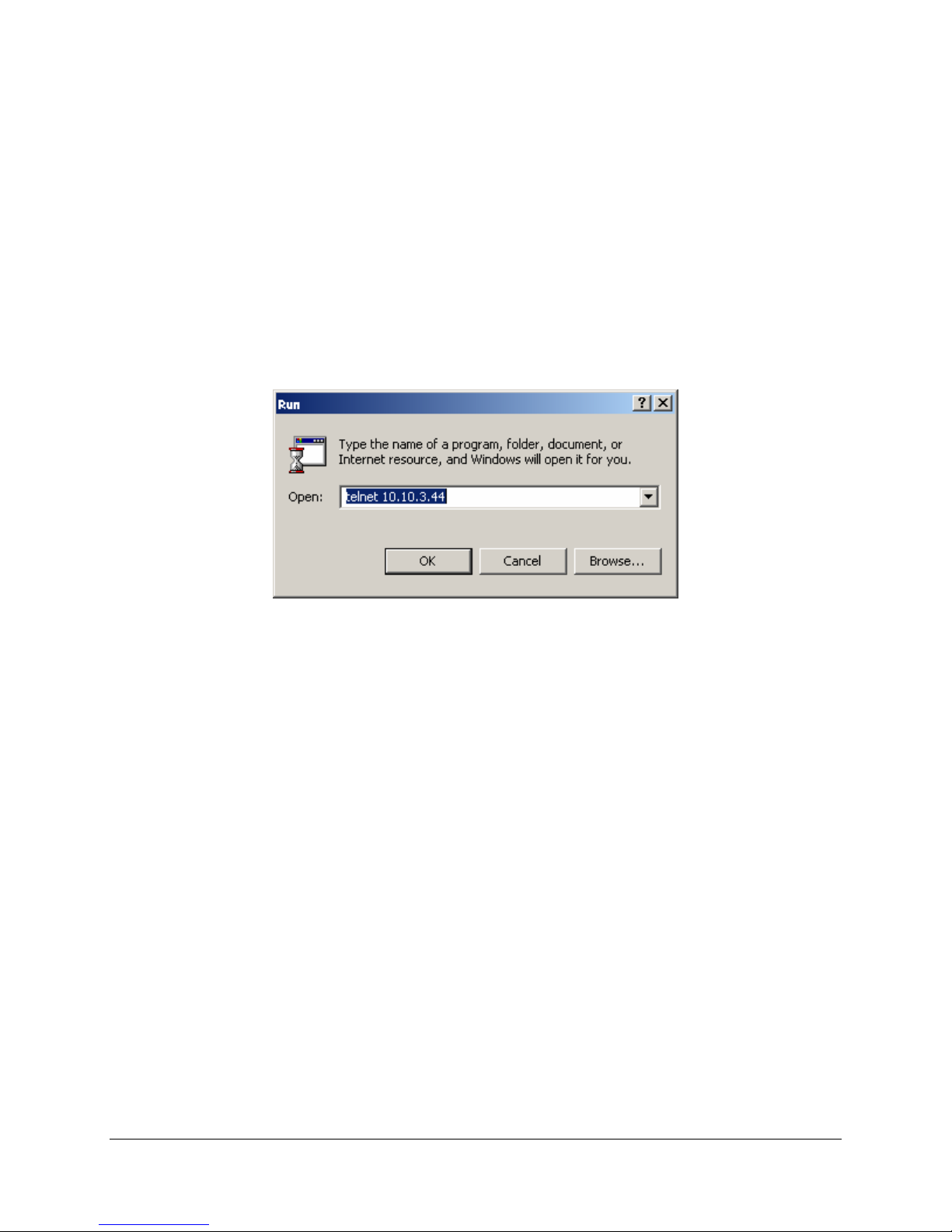
1. On a computer running Windows, open the Telnet application by selecting Start/Run from the
desktop.
2. Enter telnet command along with the IP address assigned to the unit (see below).
Figure 13: Telnet Address
3. Click OK. The MI Welcome Screen appears.
EXTender™ IP6000 Quick Installation Guide 31
Page 32
HTML Interface
The EXTender can be configured using a standard web server over an existing LAN conne ction. This
feature provides the System Administrator complete management capabilities as well as status
information for both WAN and PORT connections.
IMPORTANT:
• All IP parameters for the EXTender must be configured before the web server session can be
established.
• The EXTender must be connected to the LAN via the LAN port.
• The EXTender must be powered up and online.
Procedure
1. Access the Management Interface (MI) using a Telnet session or via the Console Port.
2. Access the Web Server parameter using the following path:
Configuration->IP->Web Server
3. Select YES for Enabled. Set the Timeout to 30.
4. Save the settings and Log out of the MI.
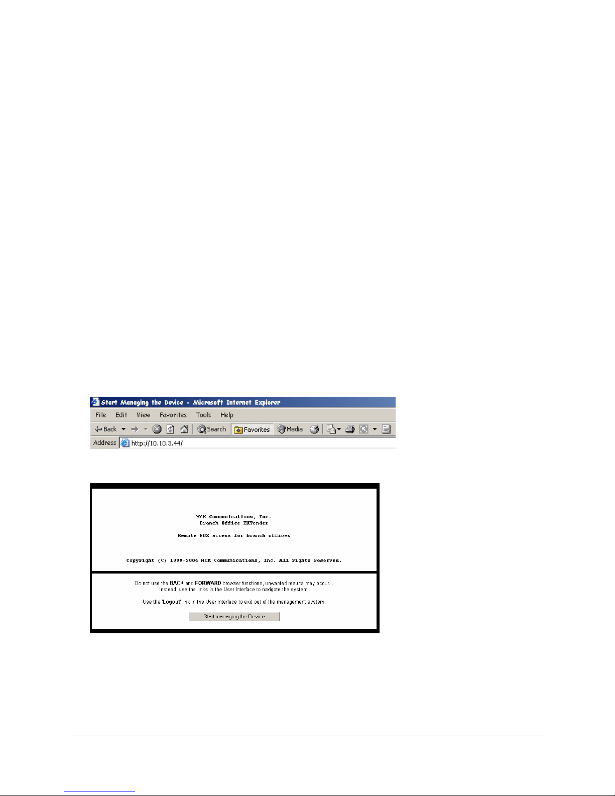
5. Open a web browser from your PC. Note: Only Windows Internet Explorer (version 5.X or higher) is
supported.
6. At the http:// prompt type in the IP Address of the EXTender as shown below.
7. The HTML pop-up window will appear. Read the instructions!
EXTender™ IP6000 Quick Installation Guide 32
Page 33
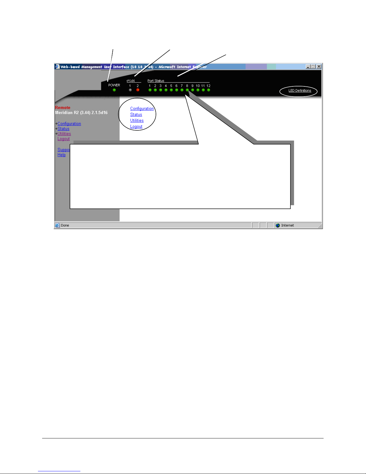
8. Double click the Start Managing the Device link.
9. The Main menu will appear.
LED States:
PWR: Solid Green
WAN1: Solid Green (Ready) if a synchronous device is connected to WAN
Solid Orange (Ready) if an asynchronous ISDN TA is connected
Port LEDs: Solid Green if connected properly to PBX.
Power LED WAN LEDs Port LEDs
1.
and accepting commands (but there is no link up- in Call Suspend
mode or have not dialed it yet).
Figure 14: HTML View
10. The Management Interface is now accessible for complete EXTender configuration.
11. Clicking on the LED Definitions in the upper right corner will give you a graphical representation of
the LED states and their definitions.
EXTender™ IP6000 Quick Installation Guide 33
Page 34

Placing a Call
What to verify before placing a call:
• The Gateway recognizes ports on the PBX and the EXTender recognizes telephones. The MI should
display “RD” (Ready).
• The Terminal device is properly configured to meet the requirements of the install.
Using the digital telephones connected to the EXTender
Once the EXTender is installed and powered-up, go on-line with the telephones at the Branch Office
location. Follow the procedure below to place a call.
Procedure
At the Branch Office location, the telephones should display the following message:
Will display Press 1 to connect if Auto Connect has been Enabled. If Auto Connect has not been
Enabled, press 1 to connect as well. Note, that the “Press 1 to Connect, will not be displayed.
Press 1 on the keypad to connect the telephone to the corporate PBX.
Place a test call and check for clear reception.
Note: If the connection is “noisy” or non-existent, refer to the System Administrator’s Guide for troubleshooting steps.
Placing an 911 Analog Call (if purchased)
Note: This procedure applies only to the single analog telephone line connected to the EXTender and
only digital telephones can utilize this feature. You must install and wire the EXTender according to the
procedures on page
Please refer to
911 calls.
18 of this document. The analog line card is not available outside North America.
Setting up the Analog Port on page 40 for instructions on configuring the analog port for
Lifeline or 911 Phone Notice
CAUTION: THIS IS NOT A LIFELINE or 911 PHONE.
If you dial 911 on your display telephone, when the telephone is connected to the Branch unit and linked
to the Gateway, you will reach the 911 facility that serves the location of the corporate facility and not the
location of your Remote unit. To ensure that you reach the correct 911 service for your area, use a
telephone connected locally.
Note: EXTender units that are equipped with an analog card provide an analog port for local dialing.
EXTender™ IP6000 Quick Installation Guide 34
Page 35

Remote Telephone Messages
The following messages appear on the remote telephone display connected to the Rem ote Unit when a
connection attempt fails. The telephone shows Connect Error, followed by a message. Table 9:
Connect Error Messages below, contains the possible Connect Error messages.
Table 9: Connect Error Messages
Message Description Action
Already connected Remote port is already connected. Reset port at the Gateway.
Assigned port The switch port is being used by
Busy (see note)
Assigned port The switch port is not available, due Check port connection at the
Down (see note) to problems (green flicker) with the
(see note) Attempt to reconnect after network is
Connect rejected The system rejects the co nnection
Connect Timeout The EXTender cannot connect to
Network disabled The network device is not
Network down The network device has a problem. Check network link and device.
Network in use The network device is being used by
Network not ready The network device is not ready for
No bandwidth The unit bandwidth is
Normal take down Displayed when the network device
No Voice path The unit bandwidth is
(see note)
Peer disconnect Displayed when the Switch unit has
Note: This message is not preceded by “Connect error”.
another user.
port.
to the PBX is lost.
request.
the
PBXgateway.
connected, being used, or is not
active.
another device.
use. (yellow LED)
oversubscribed. No network
bandwidth is available for telephone
signaling
is either being rebooted or reset.
oversubscribed. No network
bandwidth is available for voice.
disconnected from the network
device.
Wait until port is available or reset port
on the PBXgateway and try to reconnect.
PBXgateway.
Check network links. Carrier Lost Displayed if the network connection
up and running.
Make sure the Connect Password is
correct.
Check network links.
Attempt to reconnect.
Check WAN connection on the unit
Check network link and device.
Reset WAN and try to re-connect.
Make sure primary connect matches
“enabled” WAN port.
Change voice compression.
Wait until the WAN link LED is solid
green, and then attempt to re-connect.
Change voice compression.
Check the voice compression or
network at the PBXgateway.
EXTender™ IP6000 Quick Installation Guide 35
Page 36

Optional Configuration
The EXTender MI has optional configuration parameters providing the following capabilities: Refer to the
System Administrator’s Guide for more information on configuring these options.
Auto-Connect – This is a Remote module option, which automatically connects remote users
(telephones) when the EXTender is re-booted or brought on-line. (This eliminates the need to press “1”
on the Remote telephone.) Enable this feature for non-display telephones since you cannot see the
“Press ‘1’ to Connect” message.
Admin Password – If configured, this option restricts access to the EXTender MI, by requiring a password for entry. You must enter the Admin Password before you change any configuration parameters.
Note: The Gateway and EXTender units have their own separate Admin Passwords.
Connect Password – This option provides a secure WAN link between the Gateway and EXTender. If
configured, a Connect Password is required for each telephone to connect to the Gateway.
User ID - If configured, this option assigns an ID that maps the Remote Unit to the correct port on the
PBX. The remote user must enter this ID to connect to the Gateway.
Active Call Monitoring (Norstar Only) – If enabled, this allows a user, such as an Office Administrator,
to monitor users that are on Active Calls as to not disturb them and direct the call to their voice mail.
EXTender™ IP6000 Quick Installation Guide 36
Page 37
2 to 1 Configuration
RVP_Direct
The EXTender Remote Unit communicates with the Gateway installed at the corporate facility. The
Gateway can connect to two different EXTender remote units using RVP_Direct to both WAN Ports. The
first remote is connected to WAN1 of the Gateway and the second remote is connected to WAN2 of the
Gateway. Once you configure the Gateway to accommodate two separate remote units, you must
configure the following EXTender parameters:
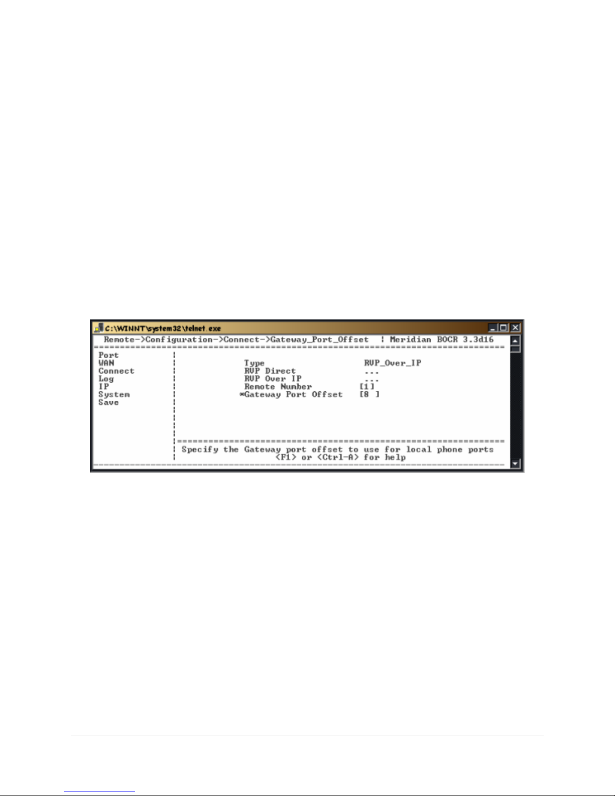
Remote Number: This number (1 or 2) identifies the Gateway WAN port connected to the EXTender.
Gateway Port Offset: This parameter is used to allow the lower port numbers on Remote 2 access to the
Gateway unit.
Example: If the Gateway port offset is set to 8, when port 1 on the Remote connects, it connects to port 9
on the Gateway.
Procedure
1. Access the Connect menu using the following path:
Path: Remote->Configuration->Connect
The following menu appears:
Figure 15: Gateway Port Offset
2. Press the Æ key, then the Èkey to access the Gateway Port Offset parameter. Enter a digit (1-8) to
set the value and press Enter. Entering 0 would mean there is no port offset value, or there is no 2:1
configuration.
3. Press the Çand Æ keys to access the RVP_Direct menu.
EXTender™ IP6000 Quick Installation Guide 37
Page 38
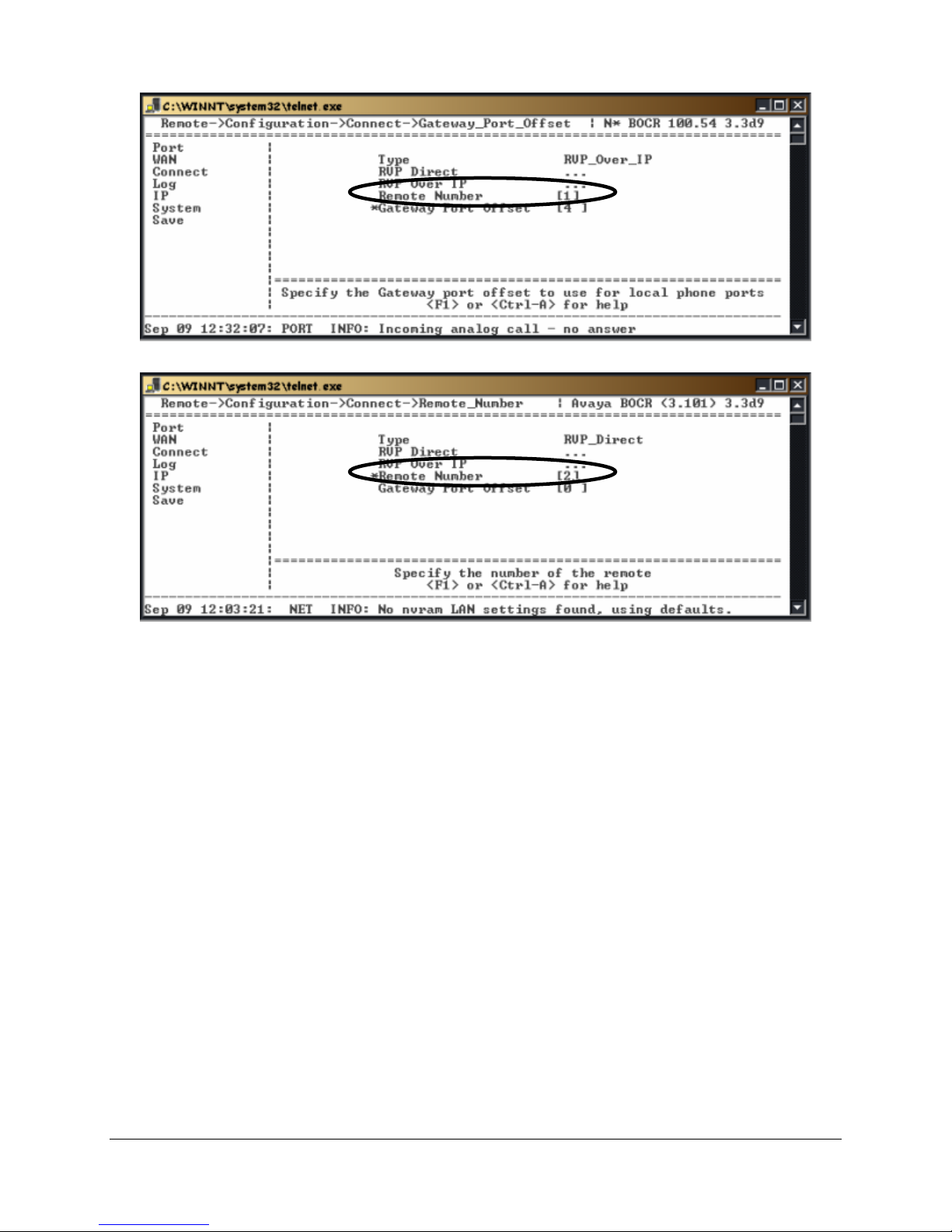
4. Press the Æ key to access the Remote Number parameter. Set to either 1 or 2. This will differentiate
the 2 remotes to the PBXgateway in the 2 to 1 configuration.
Figure 16: Remote #1
Figure 17: Remote #2
IMPORTANT NOTE: The Remote Unit connected to WAN 1 of the Gateway MUST be Remote [1].
5. Press the Å and È key to the Save option. Press Enter to save changes to the active config (.rem).
EXTender™ IP6000 Quick Installation Guide 38
Page 39
RVP_Over_IP
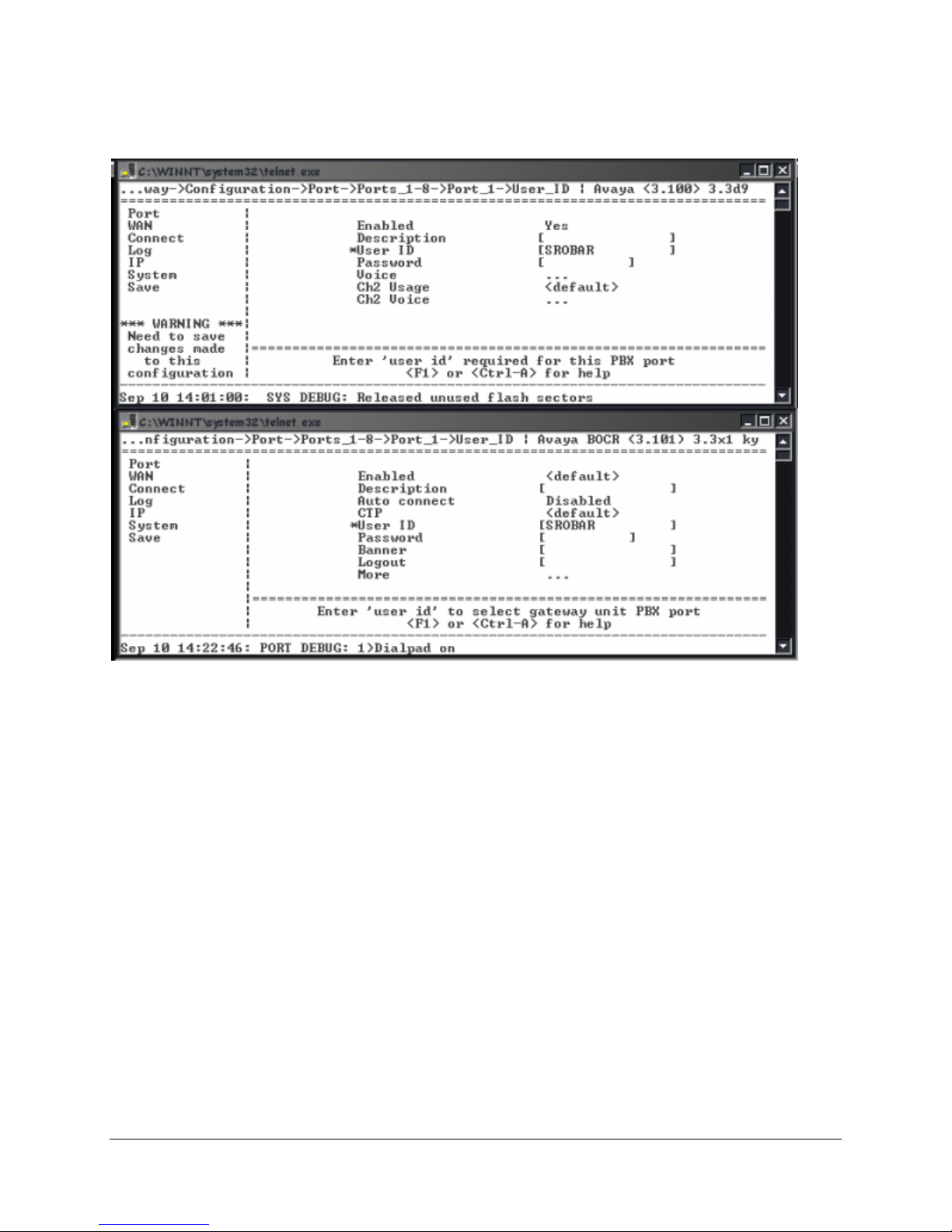
When configuring the remote units for 2:1 operation, you need to set the Remote Number. Instead of
using the Gateway Port Offset parameter to distinguish ports on each remote the Port User ID’s can be
used to determine what ports on the Remote will match up to what ports on the Gateway.
Figure 18: User IDs – 2:1 RVP_Over _IP
EXTender™ IP6000 Quick Installation Guide 39
Page 40
Setting up the Analog Port
Note: When using the Analog Port ensure that you selected the correct region using the Setup Wizard
(see page
The EXTender 6000 may be equipped with an extra RJ-11 port on the back panel. This port is labeled
“Analog” and it provides a connection to an analog telephone line (provided at the remote location) for the
purpose of placing local or emergency calls.
Once the unit is connected to the analog line, the remote user simply presses the assigned key on the
digital telephone and dials the telephone number. Only one remote user can dial out at any one time.
IMPORTANT NOTES:
• If power to the remote unit fails, the Analog port is not available to the digital telephones.
• If another telephone tries to use the analog line while it is busy, it hears a “Busy” tone.
• The set will display “In Use” and list what port is currently using the Analog Port.
Procedure
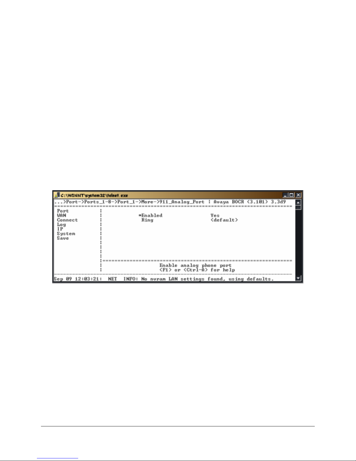
1. Select Analog Card using the following path:
Path: Remote->Configuration->Port_1-8->Port_1->More->911_Analog_Port
The following menu appears:
28).
Figure 19: Individual Port – 911 Analog Port Setup
2. Press the Æ key to enable (Yes) analog port access for all 8 or 12 ports, or press the ↓ key to set
individual ports. You may also set this in the Default Port menu and have all other ports read from this
as the <Default>.
Note: This procedure sets the <Default> setting for all ports.
EXTender™ IP6000 Quick Installation Guide 40
Page 41
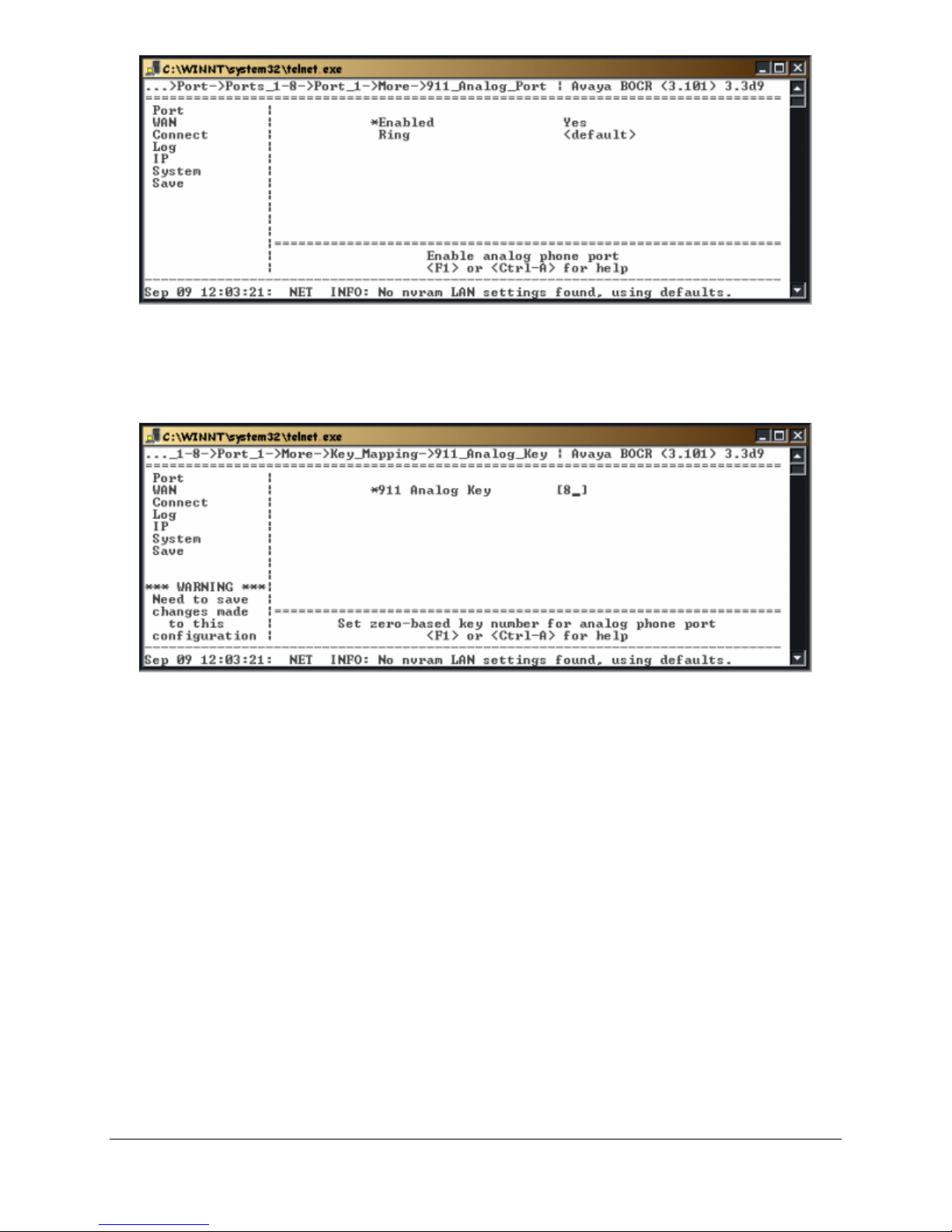
Figure 20: Default Port - 911 Analog Port Setup
3. Press the Ækey to enable or disable the analog port.
4. Press the Èkey to enable Ring (yes) on incoming analog calls
5. Access the 911 Analog Key using the following path:
Path: Remote->Configuration->Port_1-8->Port_1->More->Key Mapping
Figure 21: 911 Analog Key Mapping
5. Press the È key to set the numeric “key”, which must be pressed on the remote telephone before
placing an analog call.
Note: Do not use a key that already has a PBX function or feature programmed.
6. Press the Åkey to accept changes and go back to the Configuration Menu.
7. Press the Èkey to the Save option. Press Enter.
Setting the Make Set Busy Key
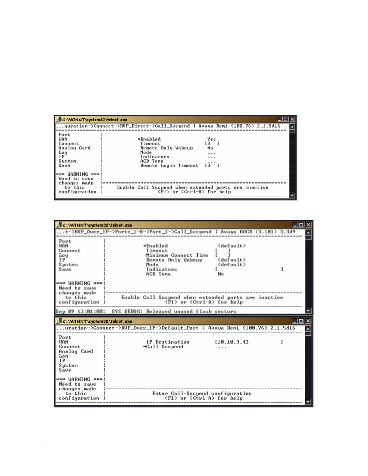
The MSB (Make Set Busy) key sends a command from the Gateway to the PBX. This command is used
to log agents out of the ACD queue in the event of an abnormal disconnect. This prevents ACD agents
from receiving calls during a network outage. The MSB function is programmed to represent a button on
the telephone which will be pressed in the event of an abnormal disconnect. In an ACD agent application,
this key should be programmed as the Unavailable Key. In a non-ACD application, this key should be
programmed as the Hold/DND or Hold/Quick Forward Key.
Procedure
1. Go to any Port menu using the following path as an example:
Path: Remote>Configuration->Port->Ports_1-8->Port_1
The following menu appears:
EXTender™ IP6000 Quick Installation Guide 41
(Meridian Only)
Page 42
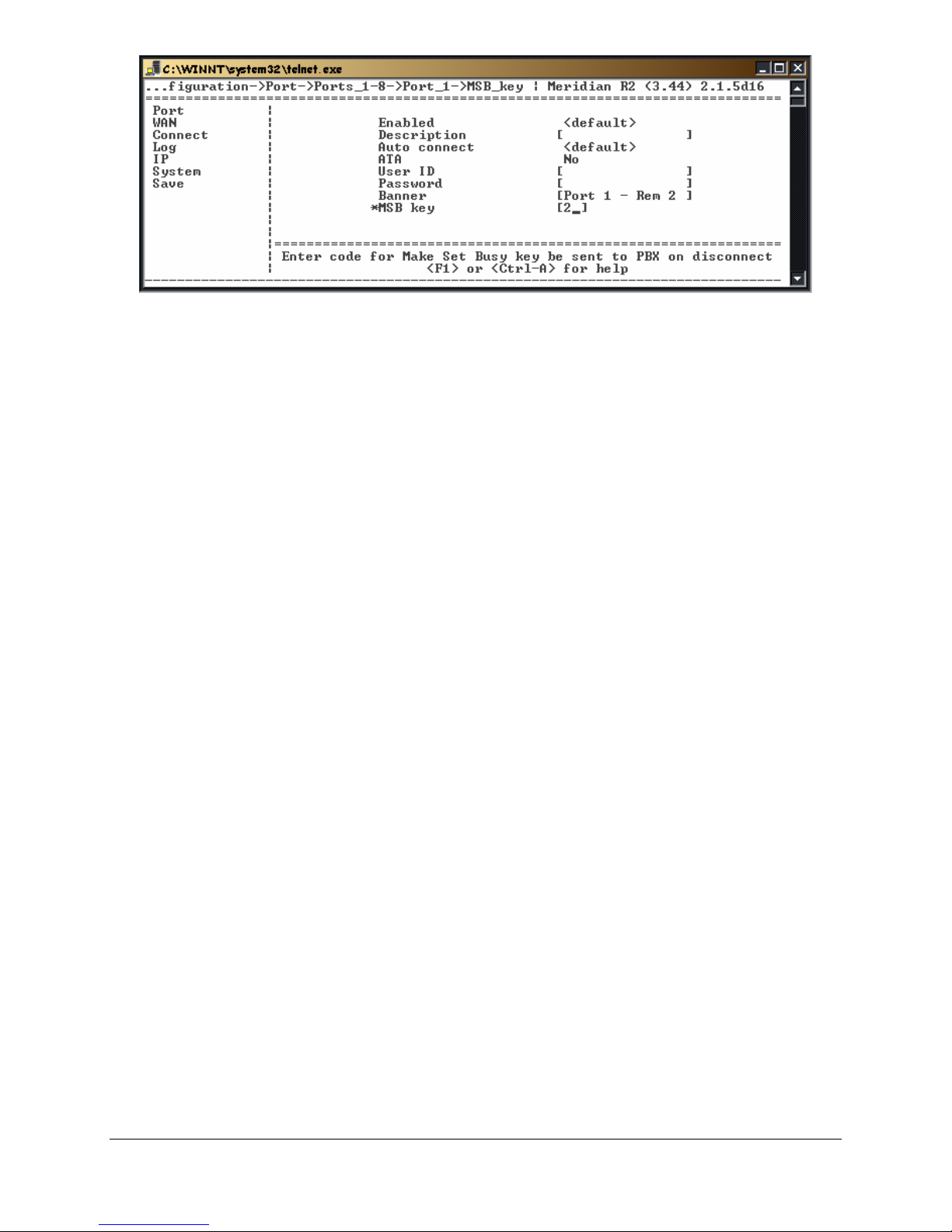
Figure 22: MSB Key
2. Press the ↓ key to scroll down to the MSB key parameter.
3. Enter the location of the MSB key on the telephone.
4. Press the ← key to accept changes and go back to the Configuration Menu.
5. Press the ← key to the Save option. Press Enter.
Setting up Call-Suspend
The Call Suspend feature allows the telecom manager to reduce communication costs by bringing d own
the ISDN/IP connection when all phones are inactive for a configurable period of time. When the line is
disconnected the phones indicate that they are in the Call Suspend mode. Whenever a user goes offhook or an incoming call occurs, the ISDN/IP connection is brought back up and all phones are taken out
of Call Suspend mode.
The Call Suspend feature operates with the assumption that if the ISDN connection is brought down, it is
possible to get busy signals from the ISDN/IP network preventing the EXTenders from communicating
and causing an interruption of telephone service to the branch office. This assumption leads to setting the
Call Suspend timer to a value that does not allow the ISDN/IP connection to go down during normal
business hours.
The expected usage pattern for the ISDN/IP connection is that at the beginning of the business day, the
phones are brought out of Call Suspend mode bringing up the IDSN/IP connection when the first user
either goes off-hook or an incoming call arrives. The ISDN/IP connection remains up for the remainder of
the business day because all phones are not idle longer than the Call Suspend timeout value. At the end
of the day, all phones become inactive for the Call Suspend timeout value and the ISDN/IP connection is
brought down. If anyone works late or comes in early, normal usage brings up the ISDN/IP connection
again.
EXTender™ IP6000 Quick Installation Guide 42
Page 43
Procedure for Avaya and Meridian (EXTender Configuration)
Note: When using an RVP_Direct connection, and Call Suspend is enabled, all ports will have call
suspend enabled. If using and RVP_Over_IP connection Call Suspend can be enabled on a port-by-po rt
basis.
1. Access the Call_Suspend Menu using the following path;
Path: Remote->Configuration->Connect->RVP_Direct->Call_Suspend
Path: Remote->Configuration->Connect->RVP_Over_IP->Default_Port
Or for individual ports:
Path: Remote->Configuration->Connect->RVP_Direct->Port_x-y->Port_x
The following menu appears.
Figure 23: RVP_Direct Call Suspend
2. Press the → key to access the parameters.
3. Press theÆ key to the Enabled parameter. Press the → key to select Yes.
EXTender™ IP6000 Quick Installation Guide 43
Figure 24: RVP_Over_IP Call Suspend
Page 44
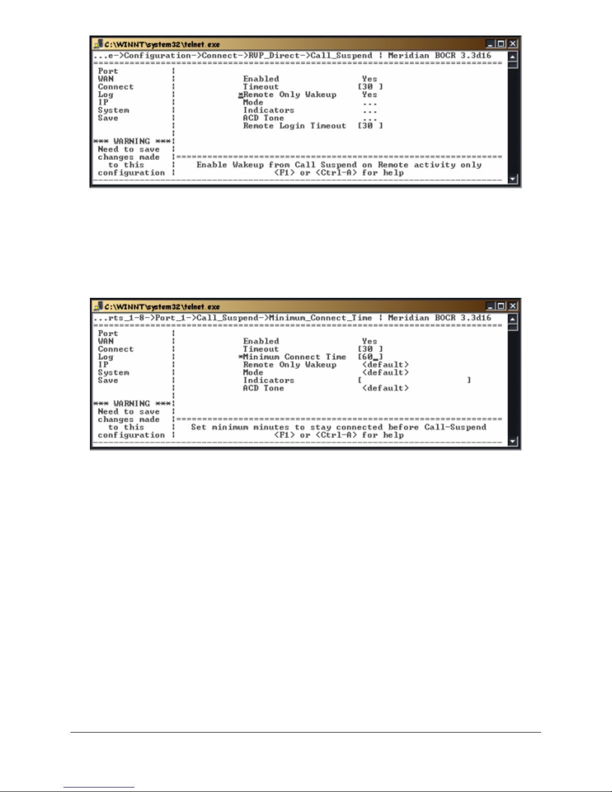
Figure 25: Call_Suspend Settings
4. Press the È and Ækey to the Timeout parameter. This parameter causes the units to go into Call
Suspend mode when no activity occurs for the set Timeout value. Set the value between 15 and 240
minutes.
6. (RVP_Over_IP Only) Press the È and Ækey to the Minimum Connect Time parameter Enter a
value, in minutes (0 –240) that the EXTender will be connected to the Gateway before falling into Call
Suspend.
Path: Remote->Configuration->Connect->RVP_Over_IP->Default_Port
Or for individual ports:
Figure 26: Min Connect Timeout
7. Press the È and Ækey to the Remote Only Wakeup parameter. If you set this parameter to Yes, you
enable wakeup from Call Suspend on activity at the Branch site only (for example, when a telephone
set goes off-hook or a key is pressed). If you set this parameter to No (disabled), incoming calls can
also cause wakeup from Call Suspend.
8. Press the Èand Æ key to the Mode parameter. This sub-menu sets the Call Suspend mode for each
port. The choices are Ring, or Lamp.
Note: Use Ring mode for non-ACD sets, and use “Lamp” for ACD sets.
9. If you have selected Lamp mode for any ports, press the È and Ækey to the Indicators parameter.
This parameter sets the Lamp indicators that you want to monitor on the telephone.
Note: Normally you should select call-appearance La mps.
10. If the Remote has ACD sets with Headsets, press the È and Ækey to the ACD Tone parameter.
Enable the ACD Tone for each port that has an ACD telephone with Headset.
11. Press the Åkey to accept changes and go back to the Configuration Menu.
12. Press the Èkey to the Save parameter. Press Enter to save changes to the active config (.rem) file.
Note: Make sure the “Dial-up” and “Dialback” numbers are programmed.
Procedure for Avaya and Meridian (Gateway Configuration)
There is a problem when the gateway reboots because the remote unit has no way of knowing that the
gateway has lost synchronization. Until the two units re-synchronize, all incoming calls will be ignored. To
EXTender™ IP6000 Quick Installation Guide 44
Page 45
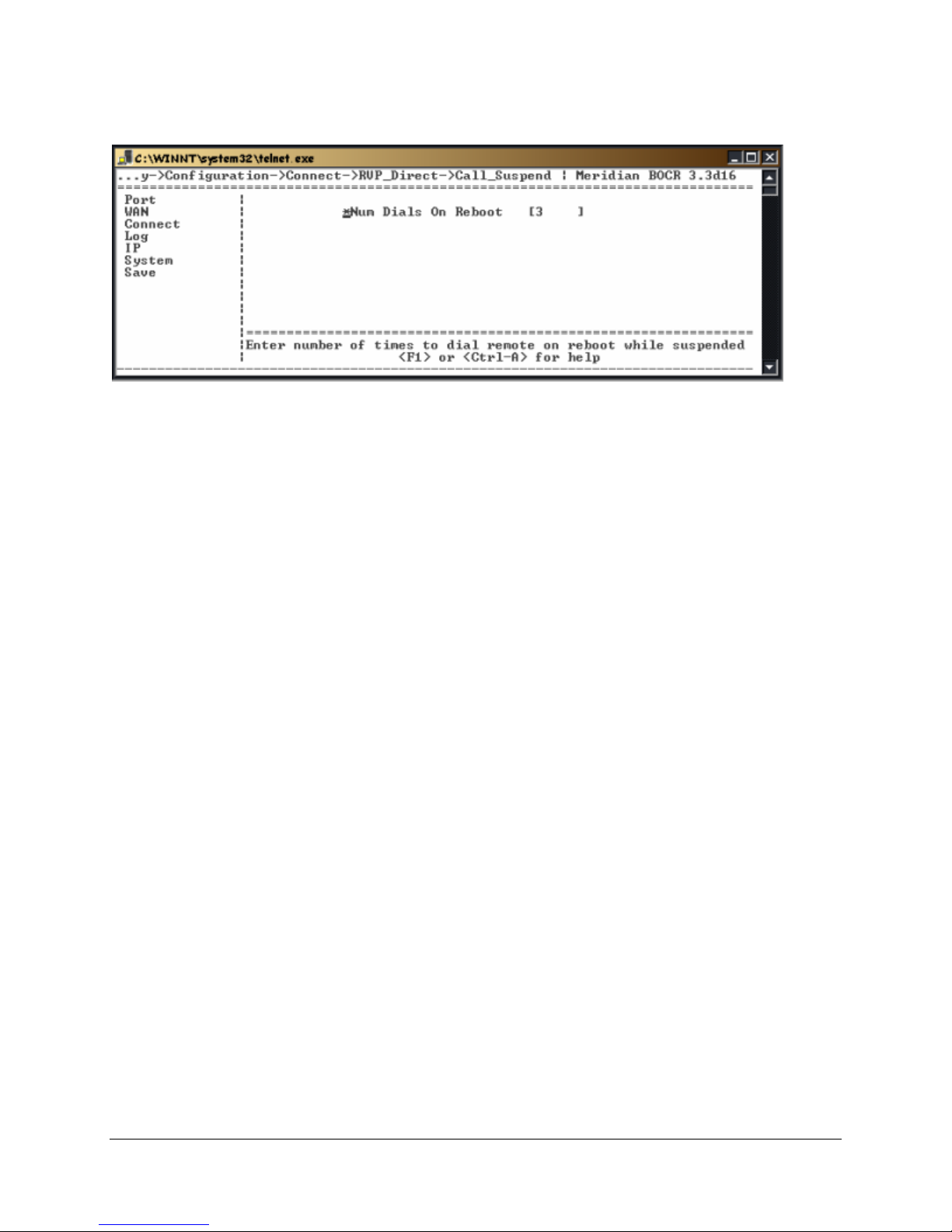
resolve this issue, the gateway unit will attempt to re-connect to the remote unit a configurable number of
times, this is called Num Dials on Reboot (assumes the network link and the remote unit are still
functioning).
Gateway Æ Configuration Æ Connect Æ RVP_Direct Æ Call Suspend
Figure 27: Num Dials on Reboot
EXTender™ IP6000 Quick Installation Guide 45
Page 46
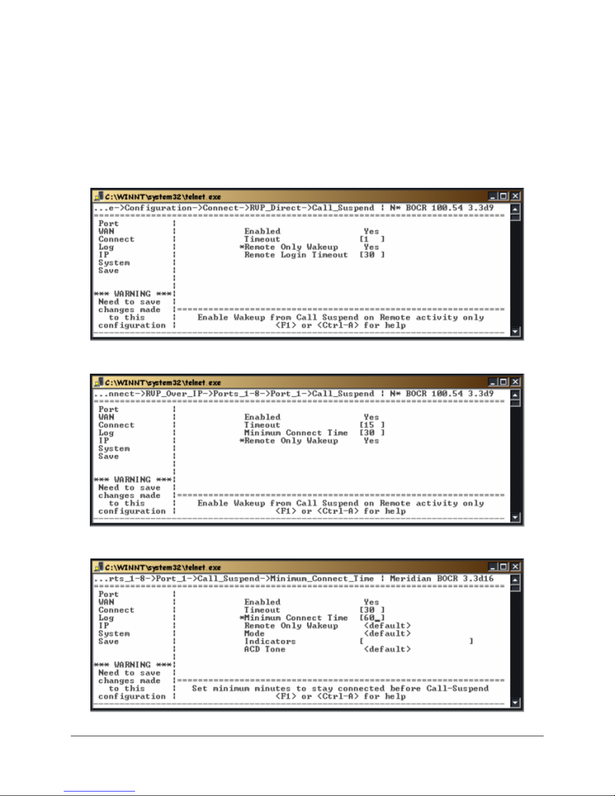
Procedure for Norstar (EXTender Configuration)
1. Access the Call_Suspend Menu using the following path;
Note: When using an RVP_Direct connection, and Call Suspend is enabled, all ports will have call
suspend enabled. If using and RVP_Over_IP connection, Call Suspend can be enabled on a port-byport basis, using individual port values or the <Default> values.
Path: Remote->Configuration->Connect->RVP_Direct->Call_Suspend
Path: Remote->Configuration->Connect->RVP_over_IP->Default_Port
Or for individual ports:
The following menu appears.
Figure 28: RVP_Direct Call Suspend
3. Press theÆ key to the Enabled parameter. Press the → key to select Yes.
Figure 29: RVP_Over IP Call_Suspend Settings
EXTender™ IP6000 Quick Installation Guide 46
Page 47
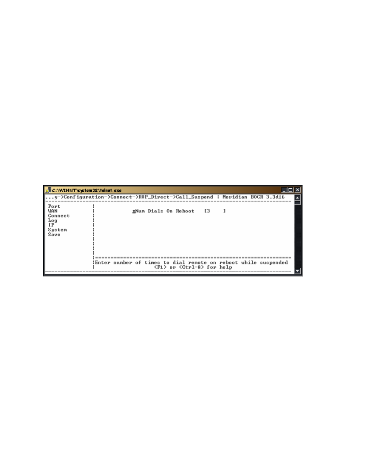
Figure 30: RVP_Direct Call_Suspend Settings
4. Press the Èand Ækey to the Timeout parameter. This parameter causes the units to go into Call
Suspend mode when no activity occurs for the set Timeout value. Set the value between 15 and 240
minutes.
5. (RVP_Over_IP Only) Press the È and Ækey to the Minimum Connect Time parameter. Enter a
value, in minutes (0 –240) that the EXTender will be connected to the Gateway before falling into Call
Suspend.
6. Press the È and Ækey to the Remote Only Wakeup parameter. If you set this parameter to Yes, you
enable wakeup from Call Suspend on activity at the Branch site only (for example, when a telephone
set goes off-hook or a key is pressed). If you set this parameter to No (disabled), incoming calls can
also cause wakeup from Call Suspend.
7. Press the È and Ækey to the Remote Login Timeout parameter. Enter a value, in minutes (15 –
240) that the EXTender will be idle, before Call Suspend is enabled.
8. Press the Åkey to accept changes and go back to the Configuration Menu.
Procedure for Norstar (Gateway Configuration)
There is a problem when the gateway reboots because the remote unit has no way of knowing that the
gateway has lost synchronization. Until the two units re-synchronize, all incoming calls will be ignored. To
resolve this issue, the gateway unit will attempt to re-connect to the remote unit a configurable number of
times, this is called Num Dials on Reboot (assumes the network link and the remote unit are still
functioning).
Gateway Æ Configuration Æ Connect Æ RVP_Direct Æ Call Suspend
Figure 31: Num Dials on Reboot
EXTender™ IP6000 Quick Installation Guide 47
Page 48
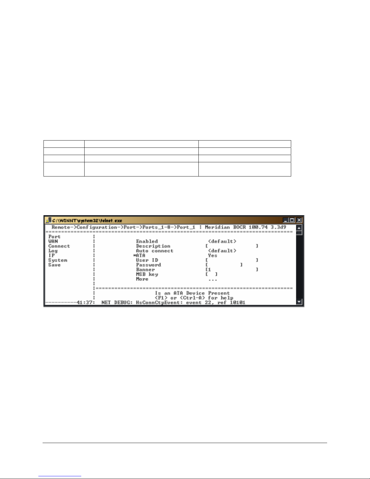
Fax Support on the Second B (Ch 2) Channel
This feature is supported on Meridian and DEFINITY protocols only.
Note: On the DEFINITY, the B channel is known as the I channel.
You are able to send analog modem traffic over the 2
PBXgateway unit.
Each of the ports on an EXTender 6000 or PBXgateway will extend both of the Meridian PBX/DEFINITY
ECS B channels, allowing the use of the second B channel for analog applications such as fax and
modem. You can send faxes by simply connecting the fax machine to the expansion card in the digital
telephone connected to the remote unit.
The analog port will have the label based upon the telephone type used:
Table 10: Fax Support by Protocol
Protocol Telephone Name of Analog Port
Avaya 6400 Series 100A Analog Interface Module
Avaya 8411D Analog Adjunct
Meridian M2006, M2008, M2008HF, M2616,
M2216ACD, M3905, M3904, M3903
(Meridian) If you have a B2 device running off your digital set, ensure you enable the ATA menu item in
the following location:
Remote->Configuration->Port->Ports_x-y->Port_x
nd
B channel (Ch2) of each port on a remote or a
ATA (Analog Terminal Adapter)
Using an MCA Adapter with a Meridian Telephone
Note: This information applies to Meridian protocols only.
Because of an error in the way the Meridian PBX sets up a port with an ATA, you must follow the steps
below to get the PBX to properly recognize a digital port.
1. Plug the ATA unit into the extended digital telephone at the remote location and power up the ATA.
2. Connect the telephone and establish the connection to the PBX.
3. Wait until the telephone has initialized and the date and time appear in the display window.
4. Unplug the power to the ATA unit, then plug the power back in. After this has been done, the Meridian
PBX should properly recognize the configuration.
EXTender™ IP6000 Quick Installation Guide 48
Figure 32: ATA Device - Enabled
 Loading...