

Citel E-4100Z-RUC02, E-4100G-SUC02, E-4100G-SUC0241, E-4100-RUC41, E-4100Z-RUC41 Administrator's Manual
...Page 1

IP Dual Port PBXgateway
and Remote System
Administrator’s Guide
Document Number: M-4100-MUC Version: Rev AA
Page 2

IP Dual Port PBXgateway and Remote System Administrator’s Guide
Copyright Information
© Copyright 2007 Citel plc All Rights Reserved
No part of this publication, including text, examples, diagrams, or icons, may be
reproduced, transmitted, or translated in any form or by any means, electronic,
mechanical, manual, optical, or otherwise, for any purpose, without prior written
permission of Citel Technologies.
Citel Technologies and its wholly-owned subsidiaries may have patents or pending
patents applications, trademarks, copyrights, or other intellectual property rights covering
subject matter in this publication. The furnishing of this document does not give the
recipient license to these patents, trademarks, copyrights, or other intellectual properties.
Trademark Information
Citel, Citel Technologies, the Citel logo, Citel EXTender™, Citel PBXgateway and The
VoIP Migration Company are trademarks or registered trademarks of Citel or its whollyowned subsidiaries in the United States and other jurisdictions. All other trademarks,
registered trademarks, and service marks are the property of their respective owners.
Accuracy Notice
Every effort was made to ensure that the information in this guide is complete and
accurate. However, Citel makes no representations or warranties, whether expressed or
implied, as to the accuracy or completeness of these materials and shall not be liable for
any loss or damage suffered or incurred as a result of reliance upon or use of them.
2
Information in this publication is subject to change without notice. Citel Technologies
reserves the right, without prior notice, to change the equipment, designs or
documentation referred to herein as it considers necessary.
Your Responsibility for your System’s Security
Toll fraud is the use of your telecommunications system by an unauthorized party, for
example, persons other than your company’s employees, agents, subcontractors, or
persons working on your company’s behalf. Please note that there may be a risk of toll
fraud associated with your telecommunications system and, if toll fraud occurs, it can
result in substantial additional charges for your telecommunications services.
You and your System Manager/System Administrator are responsible for the security of
your system such as programming and configuring your equipment to prevent
unauthorized use. The System Manager is also responsible for reading all installation,
instruction and system administration documents provided with this product in order to
understand fully the features that can introduce risk of toll fraud and the steps that can be
taken to reduce that risk. Citel Technologies does not warrant that this product is immune
from or will prevent unauthorized use of common-carrier telecommunications services or
facilities accessed through or connected to it. Citel Technologies will not be responsible
for any charges that result from such authorized use.
Document Number: M-4100-MUC Version: Rev AA © Copyright 2007 Citel plc All Rights Reserved
Page 3
IP Dual Port PBXgateway and Remote System Administrator’s Guide
Symbols and Conventions
Important symbols and conventions used throughout this guide are shown below.
Icon Description
Important safety information. Ignoring this information may lead
to physical danger to people.
Information alerting you to potential loss of data or damage to
an application, system or device.
!
Highlights important information.
Contacting Citel Technologies
3
Mail
Email
Web
Telephone
Citel Technologies
3131 Elliott Avenue
Suite 250
Seattle, WA 98121
Citel Technologies
4040 Bowness Road NW
Calgary, AB T3B 3R7
www.citel.com
+1 877 248 3587 – select the support option
Citel Technologies
4 Wheatcroft Business Park
Landmere Lane
Edwalton
Nottinghamshire
NG12 4DG UK
Document Number: M-4100-MUC Version: Rev AA © Copyright 2007 Citel plc All Rights Reserved
Page 4
IP Dual Port PBXgateway and Remote System Administrator’s Guide
Products
The information contained within this document refers to the following products:
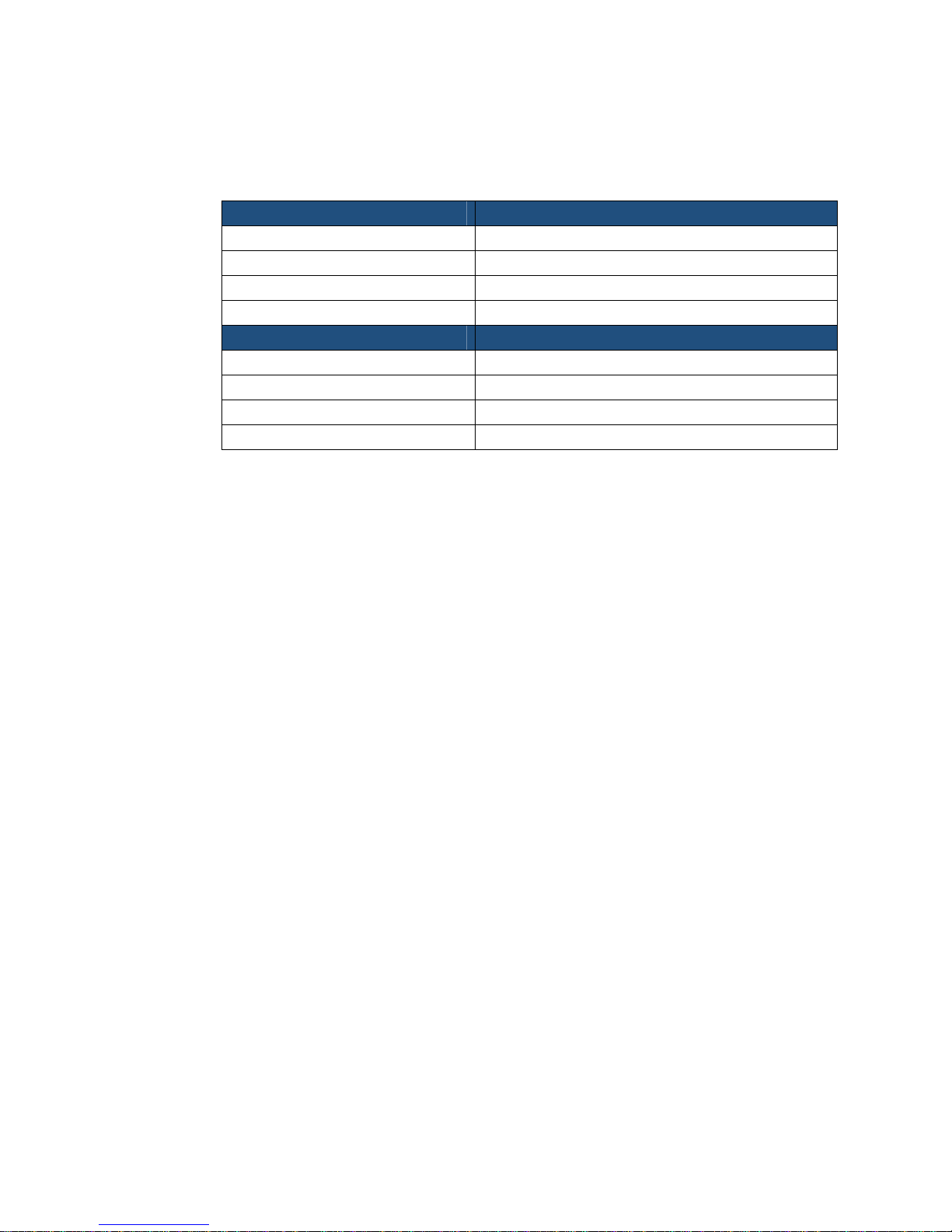
Part Number (North America) Description
E-4100G-SUC02 Dual Port PBXgateway
E-4100-RUC Single Port Remote
E-4100Z-RUC Single Port Remote with FXO
E-4100Z-RUC02 Dual Port Remote with FXO
Part Number (European Union) Description
E-4100G-SUC0241 Dual Port PBXgateway
E-4100-RUC41 Single Port Remote
E-4100Z-RUC41 Single Port Remote with FXO
E-4100Z-RUC0241 Dual Port Remote with FXO
Table 1: Product Part Numbers
4
Terms and Conventions
1. The Dual Port PBXgateway is a mutli-user communications device and is referred to
as the PBXgateway.
2. The Single Port Remote with FXO, the Dual Port Remote with FXO and the Single
Port Remote (without FXO) are referred to as the Remote. Unless otherwise stated,
instructions for the dual port version will also apply to the single port version. Images
and examples of the interface will show the dual port version.
3. The Management Console is the programming interface that is accessed through the
PC’s communications port and is referred to as the MC.
4. The Management Browser is the programming interface that is accessed through a
Web Browser and is referred to as the MB.
5. The corporate PBX (Private Branch Exchange), KTS (Key Telephone System) or KSU
(Key Service Unit) is the phone system currently used by the client. For simplicity,
they will all be referred to as the PBX.
Document Number: M-4100-MUC Version: Rev AA © Copyright 2007 Citel plc All Rights Reserved
Page 5

IP Dual Port PBXgateway and Remote System Administrator’s Guide
Safety Information
WARNING - IMPORTANT SAFETY INSTRUCTIONS
6. Read and make sure you understand all warnings and instructions, including those
marked on the product.
7. Do not install this product near water. For example in a wet basement location.
8. Do not install this product, or associated wiring, during a lightning storm.
9. Do not overload wall outlets, as this can result in the risk of fire or electrical shock.
10. Do not attach the power supply cord to building surfaces. Do not allow anything to rest
on the power cord. Do not place this product where anyone can step on the cord.
11. Do not touch non-insulated wires or terminals unless the telephone wiring has been
disconnected at the network interface.
12. Unplug the product from the wall outlet before cleaning. Use a damp cloth for
cleaning. Do not use liquid or aerosol cleaners.
13. Do not operate the system if a chemical or gas leakage is suspected in the area. Use
a telephone located in another safe area to report the trouble.
14. The mains supply AC/DC adaptor must only be used in an easily accessible outlet.
5
Power Surges
!
15. Do not open the PBXgateway or Remote. There are no user-serviceable parts inside.
Only an authorized technician should open the unit for required maintenance or
upgrading purposes.
Sudden surges in electrical current can damage sensitive equipment. To reduce the
risk of damage to your equipment caused by lightening strikes, for example, install
a surge protector between your equipment and both the AC power outlet, as well
as, the telephone line.
Document Number: M-4100-MUC Version: Rev AA © Copyright 2007 Citel plc All Rights Reserved
Page 6

IP Dual Port PBXgateway and Remote System Administrator’s Guide
6
Contents
1 OVERVIEW........................................................................................................................... 10
What is the IP Dual Port PBXgateway and Remote?........................................................ 10
What does it do?................................................................................................................10
How does it do that?.......................................................................................................... 10
Compatible products.......................................................................................................... 11
What’s in the box? ............................................................................................................. 12
More information................................................................................................................12
2 PLANNING AND PREREQUISITES ........................................................................................... 13
You Need to Check ........................................................................................................... 13
You Need to Know............................................................................................................. 14
You Need to Have ............................................................................................................. 14
You Need to Point Out....................................................................................................... 15
3 INSTALLING THE PBXGATEWAY AND REMOTE....................................................................... 16
Installation Diagram........................................................................................................... 16
Physical Installation ...........................................................................................................17
Removal............................................................................................................................. 18
4 CONNECTING TO THE PBXGATEWAY AND REMOTE................................................................ 19
Management Console ....................................................................................................... 19
Direct Serial Connection .......................................................................................... 19
Hints for Making a Successful Connection .............................................................. 21
Using the Management Console ............................................................................. 22
Command Keys ....................................................................................................... 23
Telnet Connection.................................................................................................... 24
Management Browser ....................................................................................................... 25
Connecting to the Management Browser ................................................................ 25
Enabling the Management Browser ........................................................................ 25
Configuring the Management Browser Parameters ................................................ 26
Using the Management Browser ............................................................................. 27
5 CONFIGURING THE PBXGATEWAY AND REMOTE ................................................................... 28
Initial configuration............................................................................................................. 28
The Setup Wizard .................................................................................................... 28
Changing Passwords......................................................................................................... 28
Administrator Password........................................................................................... 28
Rebooting the PBXgateway or Remote............................................................................. 29
From the Management Console .............................................................................. 29
From the Management Browser .............................................................................. 29
Essential Configuration - Quick Reference ....................................................................... 30
Advanced Configuration – Quick Reference ..................................................................... 31
Essential Configuration – PBXgateway............................................................................. 33
Essential Port Setup ................................................................................................ 33
Essential IP Parameters – LAN Address................................................................. 36
Essential IP Parameters – Telnet, Rlogin and FTP................................................. 37
Essential Configuration – Remote..................................................................................... 38
Document Number: M-4100-MUC Version: Rev AA © Copyright 2007 Citel plc All Rights Reserved
Page 7

IP Dual Port PBXgateway and Remote System Administrator’s Guide
7
Essential Port Setup ................................................................................................ 38
Essential Connect Parameters ................................................................................ 39
Essential IP Parameters – LAN Address................................................................. 40
Essential IP Parameters – Telnet, Rlogin and FTP................................................. 41
Essential Configuration of the Analog Port.............................................................. 42
Advanced Configuration – PBXgateway ........................................................................... 45
Advanced Port Setup............................................................................................... 45
Advanced System Parameters – System Name/Connect Speed ........................... 46
Advanced System Utilities – Time and Date ........................................................... 47
Advanced System Utilities – Administrator Password............................................. 47
Advanced System Utilities – Administrator Password............................................. 48
Advanced IP Parameters – Prioritizing Voice (DiffServ) ......................................... 49
Advanced IP Parameters – Static Routes ............................................................... 50
Advanced IP Parameters – DNS ............................................................................. 51
Advanced Configuration – Remote ................................................................................... 52
Advanced Port Setup............................................................................................... 52
Advanced Call Suspend Setup................................................................................ 54
Advanced System Parameters – System Settings.................................................. 56
Advanced System Utilities – Time and Date ........................................................... 57
Advanced System Utilities – Administrator Password............................................. 57
Advanced System Utilities – Administrator Password............................................. 58
Advanced IP Parameters – Static Routes ............................................................... 58
Advanced IP Parameters – Static Routes ............................................................... 59
Advanced IP Parameters – DNS ............................................................................. 60
6 OTHER MI PARAMETERS...................................................................................................... 61
7 CALCULATING BANDWIDTH REQUIREMENTS:........................................................................ 63
Determining the Number of Users..................................................................................... 63
Determining Voice Compression....................................................................................... 63
Selecting a Compression Method............................................................................ 63
Bandwidth Management Formula............................................................................ 64
8 USING SNMP...................................................................................................................... 65
MI Status Menu vs. MIB Group Table ............................................................................... 66
Major Groups of the Remote MIB............................................................................ 67
MIB Group Tables ............................................................................................................. 68
SNMP Setup......................................................................................................................71
Set Up Steps............................................................................................................ 71
Installing the MIB Files............................................................................................. 71
Setting the Community Password ........................................................................... 71
Configuring the Trap Host........................................................................................ 72
Defining a Fatal Trap ............................................................................................... 72
Defining an Error Trap ............................................................................................. 72
Defining a Warning Trap.......................................................................................... 73
Defining an Info Trap ............................................................................................... 73
Viewing the Customized Alarm Log......................................................................... 73
Using SNMP to monitor and Troubleshoot Problems.............................................. 74
9 USING SYSLOG.................................................................................................................... 75
Configuring Syslog ............................................................................................................ 75
The log priority definitions:................................................................................................. 76
Third Party Application for Syslog ..................................................................................... 76
Document Number: M-4100-MUC Version: Rev AA © Copyright 2007 Citel plc All Rights Reserved
Page 8

IP Dual Port PBXgateway and Remote System Administrator’s Guide
TROUBLESHOOTING............................................................................................................. 77
10
Baseline Checklist ............................................................................................................. 77
Network Checklist .................................................................................................... 77
PBXgateway Checklist............................................................................................. 77
Remote Checklist..................................................................................................... 78
Status LEDs....................................................................................................................... 78
Power Up Sequence................................................................................................ 78
Power up LED Sequence ........................................................................................ 79
Trouble Shooting Procedures............................................................................................ 80
System Status LEDs................................................................................................ 80
Port Status LED ....................................................................................................... 80
Resetting the Port .................................................................................................... 81
Analog Port Status LEDs ......................................................................................... 81
Test the IP Connection ............................................................................................ 82
Voice Quality Expectations................................................................................................ 82
Echo Problems ........................................................................................................ 83
Status Menus..................................................................................................................... 85
Ethernet Interface .................................................................................................... 85
IP Received Packet Statistics.................................................................................. 85
Active IP Connections.............................................................................................. 86
ARP Table................................................................................................................ 86
IP Route Table......................................................................................................... 87
General Information Screen..................................................................................... 87
Remote Phone System Messages .................................................................................... 88
8
11 CONNECTING TO OTHER CITEL PRODUCTS ........................................................................... 89
Software Compatibility....................................................................................................... 89
12 FILE MANAGEMENT AN D SYSTEM UPGRADES........................................................................ 91
Flash Files ......................................................................................................................... 91
Configuration File Management ........................................................................................ 91
Changing the Active Configuration File ................................................................... 91
Edit Non-active Configuration Files ......................................................................... 92
Creating a New Configuration File........................................................................... 92
Upgrading the Software..................................................................................................... 93
File Management............................................................................................................... 93
Examining the Flash File System ............................................................................ 93
Saving the Active Image File as the Default............................................................ 94
Querying Flash File System..................................................................................... 94
Deleting Outdated Files ........................................................................................... 95
Optimizing the Flash File System ............................................................................ 95
File Upload......................................................................................................................... 96
Via FTP.................................................................................................................... 96
Via FTP Client.......................................................................................................... 97
Via Zmodem Console Upload.................................................................................. 99
Via In-Band Upload................................................................................................ 100
File Upgrade .......................................................................................................... 101
APPENDIX A: REMOTE TELEPHONE MANAGEMENT INTERFACE................................................................. 102
Accessing the Phone-Set Interface ....................................................................... 102
Menu Legend......................................................................................................... 102
Menu Map.............................................................................................................. 103
Document Number: M-4100-MUC Version: Rev AA © Copyright 2007 Citel plc All Rights Reserved
Page 9

IP Dual Port PBXgateway and Remote System Administrator’s Guide
9
APPENDIX B:
TECHNICAL SPECIFICATIONS.............................................................................................. 104
APPENDIX C: REGULATORY AND COMPLIANCE ........................................................................................ 105
Compliance and Regulatory Statements......................................................................... 105
EN55022 and CISPR22 Statement ....................................................................... 105
FCC Part 15 Statement ......................................................................................... 105
FCC Part 68 Statement ......................................................................................... 105
The Ringer Equivalence Number (REN) ............................................................... 106
Problems, Repair and Warranty ............................................................................ 106
Industry Canada Statements ................................................................................. 106
Notice d'Industrie Canada ..................................................................................... 107
Indice d’équivalence de la sonnerie (IES) ............................................................. 107
Making Changes or Modifications ......................................................................... 108
Protection of the Environment – The WEEE Directive .................................................... 108
APPENDIX D: SUPPORTED TELEPHONES ................................................................................................. 109
APPENDIX E: GLOSSARY OF TERMS........................................................................................................ 111
Document Number: M-4100-MUC Version: Rev AA © Copyright 2007 Citel plc All Rights Reserved
Page 10

IP Dual Port PBXgateway and Remote System Administrator’s Guide
1 OVERVIEW
What is the IP Dual Port PBXgateway and Remote?
The PBXgateway is a two-user telephony device providing remote teleworkers with
seamless connectivity to the corporate PBX and all of the associated functionality. The
PBXgateway connects to the PBX and the user connects to an Remote at the remote site.
Teleworkers, typically working from an off-site location, can place or receive calls through
the corporate PBX as if they were at the main office.
What does it do?
Citel Technologies EXTender products allow workers at branch offices or home offices to
interact with the corporate PBX as if they were on-site. A simple IP connection will deliver
the voice path and telephony features over the IP network to the corporate head office.
The physical location of the worker will be completely transparent.
10
How does it do that?
The digital telephone connects to the Remote via an RJ-45 telephone jack and the
telephone traffic is sent out to the LAN via a 10/100BaseT Ethernet connection to a
PBXgateway at the corporate office. An optional PSTN FXO port on the Remote offers a
separate analog connection direct to the PSTN. This can be used for local dialing or
contacting local emergency services.
Router Router
FXO Port
(optional)
PSTN
IP Dual or
Port Single
EXTender 4100
(Remote)
IP Network
IP Dual Port
PBXgateway
(PBXgateway)
LAN
`
PC
(optional)
Figure 1: Connection Diagram
Document Number: M-4100-MUC Version: Rev AA © Copyright 2007 Citel plc All Rights Reserved
Digital
Telephone
PBX / KTS / KSU
Page 11

IP Dual Port PBXgateway and Remote System Administrator’s Guide
Compatible products
Supported EXTender products (North America and European Union):
Dual Port PBXgateway
Single Port IP EXTender
Single Port IP EXTender with FXO Port
Dual Port IP EXTender with FXO Port
Supported PBXs/KTSs/KSUs:
Avaya:
Definity R011i.02.0.110.4
IP Office Main: V3.1 (56); Expansion Module: V5.1 (56)
Magix Release 2.0, V9.0
Ericsson:
11
MD110 SW BC12 CXP1010101/3/P1U
Nortel:
Meridian Opt11c R25 Version 2111 Issue 40
Norstar BCM3.5 Release 3.5 Build 2.3a
Norstar BCM4.0 V4.0.2.03a
Norstar MICS4.1 30NdG00 NAT (V6.00)
Norstar MICS7.1 30DEC12 NAT (V3.12)
Supported Phone Types:
Avaya (refer to
Ericsson ( refer to
Nortel (refer to
Supported Telephones – Nortel Norstar
Table 15: Supported Telephones – Definity, Magix and IP Office)
Table 16: Supported Telephones – Ericsson)
Table 17: Supported Telephones – Nortel Meridian and Table 18:
)
Document Number: M-4100-MUC Version: Rev AA © Copyright 2007 Citel plc All Rights Reserved
Page 12

IP Dual Port PBXgateway and Remote System Administrator’s Guide
What’s in the box?
Dual Port PBXgateway:
Dual Port PBXgateway (1)
Citel System Administration CD (1)
Release Notes – if required (1)
Universal Power Supply A-PUNIV-1 (1)
Power Cord (1)
RJ45ST Patch Cable (1)
RJ45 to DB9 RS232 Cable (1)
Remote Single or Dual Port (with and without FXO):
Remote (1)
Citel System Administration CD (1)
12
Release Notes – if required (1)
Universal Power Supply A-PUNIV-1 (1)
Power Cord (1)
RJ45ST Patch Cable (1)
RJ45 to DB9 RS232 Cable (1)
More information
Dual Port PBXgateway Quick Installation Guide
Remote Quick Installation Guide
Information on training can be obtained from
Document Number: M-4100-MUC Version: Rev AA © Copyright 2007 Citel plc All Rights Reserved
Page 13

IP Dual Port PBXgateway and Remote System Administrator’s Guide
2 PLANNING AND PREREQUISITES
You should read the information in this chapter before starting the installation process as
you may need to obtain some information or make some changes that could be difficult
when on site.
Do NOT connect the PBXgateway to the PBX or connect the digital telephone(s) to
the Remote until the Setup Wizard has been run. An improperly configured
!
You Need to Check
PBXgateway can cause damage to the PBX line card and an improperly configured
Remote can cause damage to the digital telephone sets.
1. Which model of PBX is used at the corporate site
2. Which digital telephones at the remote location will be communicating with the
PBXgateway ports
13
3. Where the PBXgateway and Remote will be physically located
4. Access to the power to be supplied to the PBXgateway and Remote
5. The PBXgateway (at the corporate site) and the Remote (at the branch office) must
be installed properly and the network link between both devices must be operational
a) An appropriate network-terminating device must be installed and functioning at
the corporate site and the branch office supporting 10/100BaseT Ethernet
interface. The data connection between the corporate site and the Remote must
be operational and configured correctly.
b) Ensure that the correct TCP/UDP ports are opened to allow the Remote to
connect through the corporate firewall:
- PBXgateway uses TCP/UDP port 2698
- Remote uses port 12288 (and port 12290 for Dual Port Remote) for incoming
UDP streams and any port between 1024 and 65535 for outgoing TCP streams
6. Power and Wiring
7. The system is designed to operate at 120-240V AC. Do not apply power to the
PBXgateway or Remote until you are instructed to do so in the installation procedure
8. Install the PBXgateway or Remote power supply and cabling away from high
power/high RF noise devices such as computers, fans, fluorescent ballasts and power
supplies
9. Use good wiring practices. Do not run wires over fluorescent lights, computers, air
conditioners, etc., as this can introduce noise
10. The distance between the PBXgateway and the PBX it is to be connected to should
not exceed 500 feet (150 meters)
11. Ensure that the power supply is within 5 feet (1.5 meters) of the PBXgateway and the
Remote
Document Number: M-4100-MUC Version: Rev AA © Copyright 2007 Citel plc All Rights Reserved
Page 14

IP Dual Port PBXgateway and Remote System Administrator’s Guide
You Need to Know
1. IP Settings:
a) Address – This is the IP address of the PBXgateway (another unique address is
also required for the Remote)
b) Subnet Mask – A number used to identify the IP subnet on the LAN
c) Default Router – The address of a device used to reach IP hosts not on this IP
sub-network
2. What voice compression is to be used based on the number of users and available
bandwidth. The voice compression methods available are ADPCM32, ADPCM24,
G.729A, G.711 (described in the
3. The unique device names to be used for identifying the PBXgateway and Remote,
Seattle Office, New York Office, for example
4. The model number and release of the PBX in use at the corporate site
5. Corporate guidelines for password configuration and implementation
6. How to tune the voice parameters to match the IP network characteristics by adjusting
the Jitter Delay and Packet size (described in the
PBXgateway section).
Essential Port Setup of the PBXgateway section).
14
Essential Port Setup of the
7. The companding setting (aLaw – Europe, uLaw North America)
8. Any special needs or specific user requirements
You Need to Have
1. All of the items provided in the box with the PBXgateway and Remote (see What’s in
the box?
2. A copy of the latest software version available for the PBXgateway and Remote (if
performing a software upgrade)
3. Mounting screws and screw driver (if wall mounting is required)
4. Access to supported PBX ports
5. A PC or Laptop computer to connect to the Remote with the following capabilities:
a) A serial port
b) A network port
c) A terminal emulator such as Windows HyperTerminal for accessing the
PBXgateway and Remote Management Console (MC)
d) Microsoft Internet Explorer 5.x or later for configuring the PBXgateway and
Remote via the Management Browser (optional configuration method)
on page 12)
Document Number: M-4100-MUC Version: Rev AA © Copyright 2007 Citel plc All Rights Reserved
Page 15

IP Dual Port PBXgateway and Remote System Administrator’s Guide
You Need to Point Out
1. If a user dials emergency services from the remote location when the telephone is
connected to the Remote and linked to the PBX and not the location of the Remote.
To ensure that you reach the correct emergency service for your area, use a
telephone connected locally.
The Remote is available with an optional analog port for local dialing.
15
Document Number: M-4100-MUC Version: Rev AA © Copyright 2007 Citel plc All Rights Reserved
Page 16

IP Dual Port PBXgateway and Remote System Administrator’s Guide
3 INSTALLING THE PBXGATEWAY AND
REMOTE
Before handling or operating the PBXgateway and Remote, make sure that the
cover is correctly secured to the base of the unit – hazardous voltages are present
inside.
Do not attempt to modify the PBXgateway or Remote hardware.
Installation Diagram
16
Router Router
FXO Port
(optional)
PSTN
`
PC
(optional)
Figure 2: Installation Diagram
IP Dual or Single
EXTender 4100
(Remote)
Digital
Telephone
IP Network
IP Dual Port
PBXgateway
(PBXgateway)
LAN
PBX / KTS / KSU
Document Number: M-4100-MUC Version: Rev AA © Copyright 2007 Citel plc All Rights Reserved
Page 17

IP Dual Port PBXgateway and Remote System Administrator’s Guide
Physical Installation
PBXgateway (right side of Figure 1 – previous page):
1. Place the unit in the destination location. The PBXgateway can either be wall
mounted or placed on any desktop.
2. Connect the LAN port to the LAN with an RJ-45 cable
3. Prepare to connect the supplied RJ-45 to RJ-11 cable between port 1 on the rear of
the PBXgateway and a port on the PBX. Do NOT connect to the PBX until the Setup
Wizard has been run.
4. Prepare to connect the supplied RJ-45 to RJ-11 cable between port 2 on the rear of
the PBXgateway and a port on the PBX. Do NOT connect to the PBX until the Setup
Wizard has been run.
5. Connect the supplied RJ-45 to DB-9 Console cable between the console port and a
PC communications (COM) port
Do not apply power to the units until instructed to do so. An improperly configured
PBXgateway or Remote can cause damage to the units, telephone sets or PBX line
!
cards.
17
!
Remote (left side of Figure 1 – previous page):
1. Place the unit in the destination location. The Remote can either be wall mounted or
placed on any desktop.
2. Connect the supplied RJ-45 to DB-9 Console cable between the console port and a
PC communications (COM) port
3. Prepare to connect the supplied RJ-45 to RJ-11 cable between port 1 on the rear of
the Remote and a supported digital set. Do NOT connect a telephone until the Setup
Wizard has been run.
4. Prepare to connect the supplied RJ-45 to RJ-11 cable to attach between port 2 on the
rear of the Remote and a supported digital set (Dual Port Remote only). Do NOT
connect a telephone until the Setup Wizard has been run.
5. Connect the LAN port to the LAN with an RJ-45 Ethernet cable
Do not apply power to the units until instructed to do so. An improperly configured
PBXgateway or Remote can cause damage to the units, telephone sets or PBX line
cards.
Document Number: M-4100-MUC Version: Rev AA © Copyright 2007 Citel plc All Rights Reserved
Page 18

IP Dual Port PBXgateway and Remote System Administrator’s Guide
Removal
Refer to the instructions below when moving or removing the PBXgateway and/or
Remote.
1. Power down the units
2. Disconnect the RJ-45 from the LAN port
3. Disconnect the RJ-45 to RJ-11 cable between port 1 on the rear of the PBXgateway
and a port on the PBX
4. Disconnect the RJ-45 to RJ-11 cable between port 2 on the rear of the PBXgateway
and a port on the PBX
5. Disconnect the RJ-45 to RJ-11 cable between port 1 on the rear of the Remote and a
supported digital set
6. Disconnect the RJ-45 to RJ-11 cable between port 2 on the rear of the Remote and a
supported digital set
7. Disconnect the RJ-45 to DB-9 Console cable between the console port and the PC
communications (COM) port
18
8. Remove the unit(s) from the desktop or wall (if mounted)
Document Number: M-4100-MUC Version: Rev AA © Copyright 2007 Citel plc All Rights Reserved
Page 19

IP Dual Port PBXgateway and Remote System Administrator’s Guide
4 CONNECTING TO THE PBXGATEWAY
19
AND
This chapter provides information for connecting to the PBXgateway and the Remote. The
units’ Management Console (MC) and/or Management Browser (MB) can be accessed
with a PC or terminal connected in one of three ways.
A generic VT100 ETI application is needed to communicate with the PBXgateway and/or
Remote (this document will refer to examples using Microsoft HyperTerminal).
REMOTE
Management Console
The Management Console provides access to a full configuration and diagnostic and
command structure. Instructions for the three connection methods are provided in the
following pages.
Direct Serial Connection
This section describes connecting to the Management Console using Microsoft
HyperTerminal. You may use a different terminal application if you are familiar with its
use.
Only use the commands listed and described in this document unless otherwise instructed
by Citel Technologies. Incorrect command use may prevent use of the PBXgateway and
Remote.
1. Start a HyperTerminal session.
a) On a default installation of Windows, from the
Accessories, Communications and finally HyperTerminal.
2. Enter a name for the new connection in the Name box: for example, Gateway (or
Remote).
3. Select the COM port you are using from the options in the Connect drop-down list.
4. Check the configuration of the communications port and make sure the settings are
as follows:
Bits per second 9600
Data bits 8
Parity None
Stop bits 1
Flow control Xon/Xoff
5. Plug the power supply in to the PBXgateway and/or Remote and allow it to complete
the boot sequence.
Start menu select Programs,
Document Number: M-4100-MUC Version: Rev AA © Copyright 2007 Citel plc All Rights Reserved
Page 20

IP Dual Port PBXgateway and Remote System Administrator’s Guide
Do NOT connect the PBXgateway to the PBX or connect the digital telephone(s) to
the Remote until the Setup Wizard has been run. An improperly configured
!
PBXgateway can cause damage to the PBX line card and an improperly configured
Remote can cause damage to the digital telephone sets.
6. Wait a few seconds and the “Press 'Enter' to start the shell...” prompt is displayed.
20
7. Press
If the PBXgateway or Remote software is running but you do not see these prompts, the
serial connection between your computer and the units may be at fault. You must correct
this problem before you can use the HyperTerminal connection successfully. See
Serial Connection
8. Type the unit’s password, if one is set, and press Enter.
9. To be sure that you can see all the information displayed, you must set the screen
Enter. A password prompt if a displayed if a password is set (there is no default
password).
Direct
on the previous page.
The Console UI welcome screen is displayed (see
size to 24 lines x 80 columns.
The screen size is correctly set when the Welcome screen is displayed with the #
border, as shown in
Figure 3.
Figure 3 below)
Figure 3: The PBXgateway Console UI – Welcome Screen
Using your mouse, click, hold and drag the corner of the screen until you can see the
# border, then release your mouse button.
The Welcome Screen for the Remote is the same except it will display “Citel
Technologies, IP Dual Port (or Single Port) Remote”
Document Number: M-4100-MUC Version: Rev AA © Copyright 2007 Citel plc All Rights Reserved
Page 21

IP Dual Port PBXgateway and Remote System Administrator’s Guide
Hints for Making a Successful Connection
1. Check that the cable being used is a straight-through cable, as supplied with the
PBXgateway and Remote.
2. Exit and then restart HyperTerminal.
3. Connect using a different COM port on your computer.
4. Reboot your computer and then restart HyperTerminal.
5. The PBXgateway and Remote Management Console password is not set by default.
21
6. It’s strongly recommended that a password be set for security reasons. See
Passwords
for instructions.
Changing
7. Make a note of the password and pass it to the system administrator.
If the unit’s password is lost or forgotten please contact a customer support representative
at 1-877-248-3587 or [email protected] for details on how to reset the password.
Individual port passwords are not affected.
Document Number: M-4100-MUC Version: Rev AA © Copyright 2007 Citel plc All Rights Reserved
Page 22

IP Dual Port PBXgateway and Remote System Administrator’s Guide
Using the Management Console
The Welcome screen is displayed automatically when you connect to the PBXgateway
and Remote using a serial cable. You must make sure that your terminal window is sized
so that you can see the border of
Press any key to enter the console menu system. Menu options are selected using the PC
cursor keys: use the up and down keys to move within a menu or list of options, use the
left and right keys to return to a higher level menu or to access sub-menus (as described
Command Keys section on the next page).
in the
The Console Interface
# symbols around the contents.
22
A typical screen from the console interface is shown in
Figure 4 below.
Figure 4: The Console Interface
1. Menu Location - Your current location within the menu system – in the example, you
are in the Configuration menu on the PBXgateway.
2. Unit Name - Typically used to identify the unit by its location (user configurable).
3. Software Version - The version of software currently installed.
4. Menu List - The options available within the current menu. The asterisk indicates
your current location (“Port” is highlighted in
5. Data Entry Window - The area of the screen where configuration details are entered.
In this example, this is the Port configuration menu.
6. Feature Information - A short description and/or brief instructions on the current
menu item.
7. Log - An area that displays the four most recent lines from the log. Primarily used for
trouble shooting. A customer support representative will instruct the Administrator on
the use of this feature should the need arise.
8. System Status - Power indication message.
9. Port Status – Provides live information on the status of the individual ports.
Document Number: M-4100-MUC Version: Rev AA © Copyright 2007 Citel plc All Rights Reserved
Figure 4, for example).
Page 23

IP Dual Port PBXgateway and Remote System Administrator’s Guide
Command Keys
The Management Console (MC) uses command keys and cursor keys to navigate through
the sub-menus:
Key Description
Cancel, leaving values at their previous settings.
Accepts the change you have entered or exits the current
or
or
or + A
or + R
Table 2: Command Keys
menu option. The Administrator will also be prompted to
save configuration changes if required.
Access the currently selected menu item.
Go to an item in a menu. You can also select a menu
item by typing the first character in its name (“p” for Port,
for example).
Help screen. This help screen is for the UI itself and not
for the features listed within the UI.
Refreshes the current screen.
23
Saving Changes
You will be prompted to save if you attempt to log out of the Management Console when
changes have been made. You will also be asked to confirm that you want to save
changes if you select the Save option. You may need to reboot the PBXgateway or
Remote for your changes to take effect depending on the menu item programmed.
Logging Out
When you have finished working in the Management Console, remember to logout.
If you have left FTP enabled, a warning message is displayed reminding you to
disable FTP access. You can choose to logout anyway, but leaving FTP access
enabled is not recommended.
If FTP is disabled, a message is displayed asking you to confirm that you want to log
out of the Management Console.
Document Number: M-4100-MUC Version: Rev AA © Copyright 2007 Citel plc All Rights Reserved
Page 24

IP Dual Port PBXgateway and Remote System Administrator’s Guide
Telnet Connection
The Management Console for the PBXgateway and Remote can also be accessed using
a telnet session. The units have default IP parameters which can be utilized for
connection and initial configuration.
Default IP Address: 10.0.0.10
Default Subnet Mask: 255.0.0.0
1. On a PC running Microsoft Windows go to Network Connections and change the
settings on the Internet Protocol (TCP/IP) Properties. Click on “Use the following IP
address” button and enter an IP address of 10.0.0.11 and a subnet mask of 255.0.0.0.
2. Connect the PBXgateway or Remote to the PC via a LAN cable.
3. Telnet to the unit’s address of 10.0.0.10 through the VT100 Terminal emulator
(HyperTerminal) and begin configuration (see
Remote
4. Go to the Microsoft Windows “Run” application, enter “Telnet” followed by the default
address of 10.0.0.10 and hit enter. The Welcome Screen is displayed (see
). Or,
24
Configuring the PBXgateway and
Figure 3).
5. Once a valid IP address and subnet mask have been configured ensure that the
PBXgateway and Remote’s LAN cable is re-connected to the network router.
6. On the PC go back to Internet Protocol (TCP/IP) Properties and click on the “Obtain
an IP address automatically” button to put the PC’s IP info back to its original state.
Note: A maximum of two Telnet connections can be made to each unit at any one time
(not recommended due to configuration conflicts that may arise with two
administration session being performed at the same time).
Document Number: M-4100-MUC Version: Rev AA © Copyright 2007 Citel plc All Rights Reserved
Page 25
IP Dual Port PBXgateway and Remote System Administrator’s Guide
Management Browser
Connecting to the Management Browser
The PBXgateway and Remote can also be configured using a web based interface when
running Windows Internet Explorer 5.x or later. Prior to configuring through the
Management Browser, a valid IP address must first be assigned to the units and the Web
server must also be enabled. To configure the unit’s IP address and Management
Broswer settings refer to
The PBXgateway and Remote Management Browser uses JavaScript and Cascading
Style Sheets (CSS), therefore, you must enable JavaScript to obtain all the functions
described in this document. If you disable Cascading Style Sheets, the functions will still
work, although the appearance will differ.
Enabling the Management Browser
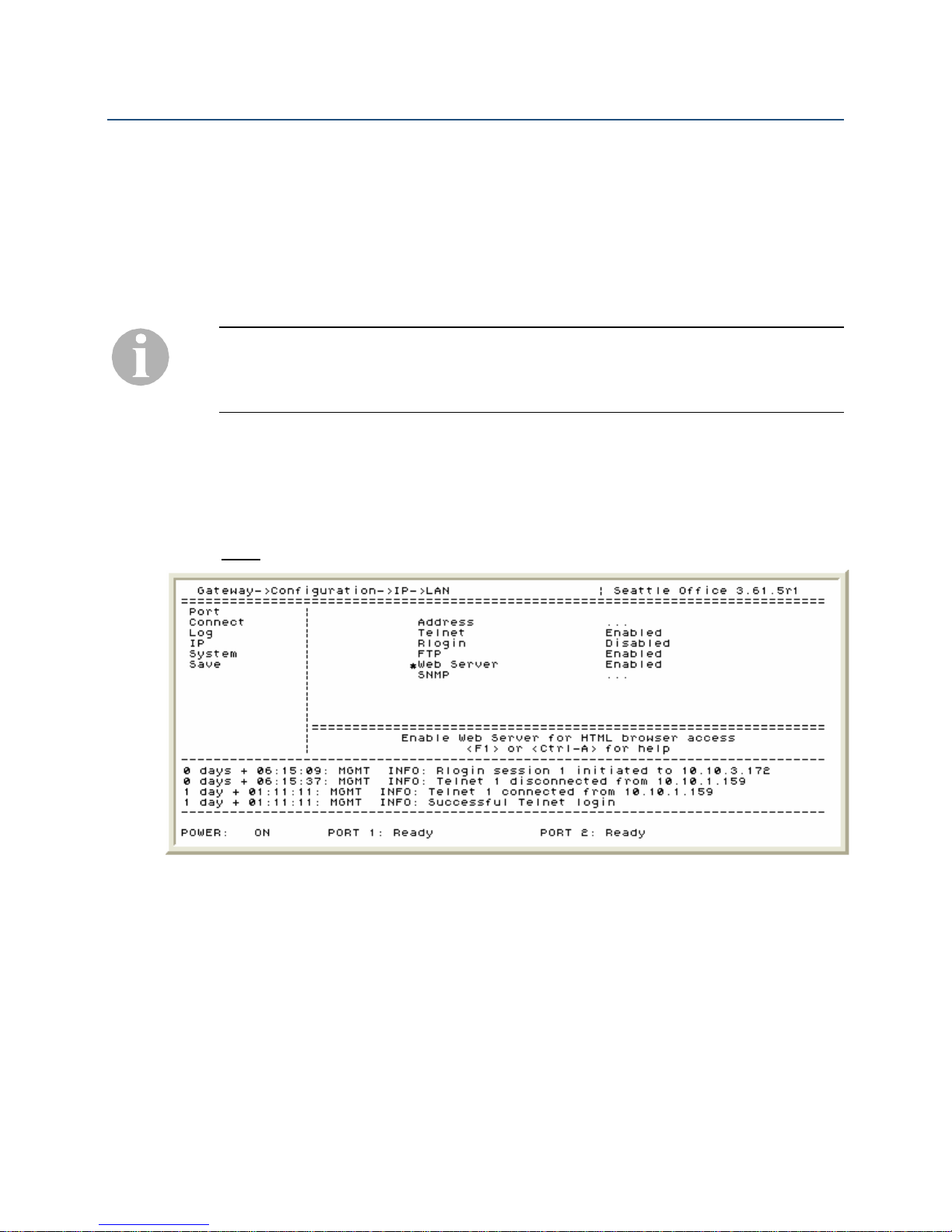
The Web Server feature must first be enabled in order to administer the units with this
method. The configuration screen to enable the Management Browser is shown below:
Direct Serial Connection or Telnet Connection.
25
Path: Gateway (and Remote) ->Configuration->IP->LAN
Figure 5: Enabling the Web Server
1. Enabling the Web Server – In order to configure the units using the Management
Browser the Web Server must first be set to “Enabled.”
Document Number: M-4100-MUC Version: Rev AA © Copyright 2007 Citel plc All Rights Reserved
Page 26

IP Dual Port PBXgateway and Remote System Administrator’s Guide
Configuring the Management Browser Parameters
Additional Management Browser (MB) parameters can also be configured either prior to
launching the MB or any time after. The MB parameters screen is shown below:
Path: Gateway (and Remote) ->Configuration->IP
Figure 6: Management Browser Parameters
26
1. Setting the Web Timeout – For security purposes, this parameter determines the
amount of time a MB screen can be left idle (no programming activity) before
terminating the session. The timeout can be set for 30 minutes, 1, 2 or 3 hours or
Never (not recommended).
2. Enabling the Web Refresh LED – The graphical representation of the PBXgateway
and Remote will update the Port Status LEDs (see below) every 10 seconds. The
administrator will receive the most up to date status of the ports. If the frequent
updates are found to be a hindrance during programming the LED refreshing can be
disabled.
Figure 7: Management Browser Parameters
Document Number: M-4100-MUC Version: Rev AA © Copyright 2007 Citel plc All Rights Reserved
Page 27

IP Dual Port PBXgateway and Remote System Administrator’s Guide
Using the Management Browser
To access the PBXgateway or Remote through the Management Browser open a
Microsoft Internet Explorer session and enter the unit’s IP address in the Address field of
the web browser. The Management Browser Welcome Screen is presented (see below).
27
Figure 8: The Management Browser Welcome Screen
Important instructions on the use of the Management Browser should be read and fully
understood before continuing to configure the units.
Click on the “Start managing the Device” button and a graphical representation of the
PBXgateway or Remote, is displayed (see below).
Figure 9: The Management Browser configuration screen
Document Number: M-4100-MUC Version: Rev AA © Copyright 2007 Citel plc All Rights Reserved
Page 28

IP Dual Port PBXgateway and Remote System Administrator’s Guide
5 CONFIGURING THE PBXGA TEWAY AND
REMOTE
The PBXgateway and Remote must be installed properly and the network link between
both devices must be operational before continuing.
Initial configuration
Do NOT connect the PBXgateway to the PBX or connect the digital telephone(s) to
the Remote until the Setup Wizard has been run. An improperly configured
!
The Setup Wizard
PBXgateway can cause damage to the PBX line card and an improperly configured
Remote can cause damage to the digital telephone sets.
The PBXgateway and Remote are programmed at the factory with “default” settings
providing basic parameters to accommodate many network environments. It may be
necessary to change these settings depending on the network and specific user or
corporate requirements.
28
The Setup Wizard is presented first with all new installations. The wizard will prompt the
Administrator to enter required information necessary for basic configuration of the
PBXgateway and Remote. Simply follow the prompts to perform a basic configuration.
Refer to this manual for a full description of the features presented when running the
Setup Wizard.
If it becomes necessary to run the Setup Wizard at any time after the initial installation it
can be accessed here:
Path: Gateway (and Remote) ->Utilities->Setup Wizard
Changing Passwords
Administrator Password
The administrator password provides access to the MC (Management Console). It is very
important to set an administrator password for PBXgateway and Remote because the
units are shipped with no default password. Always keep passwords in a secure location.
Although setting the administrator password is described later in this document as part of
the configuration steps it can be changed at any time after the initial installation here:
Path: Gateway (and Remote) ->Utilities->System->Set Password
If the unit’s password is lost or forgotten please contact a customer support representative
at 1-877-248-3587 or [email protected] for details on how to reset the password.
Individual port passwords are not affected.
Document Number: M-4100-MUC Version: Rev AA © Copyright 2007 Citel plc All Rights Reserved
Page 29
IP Dual Port PBXgateway and Remote System Administrator’s Guide
Rebooting the PBXgateway or Remote
From the Management Console
To reboot the system from the Management Console:
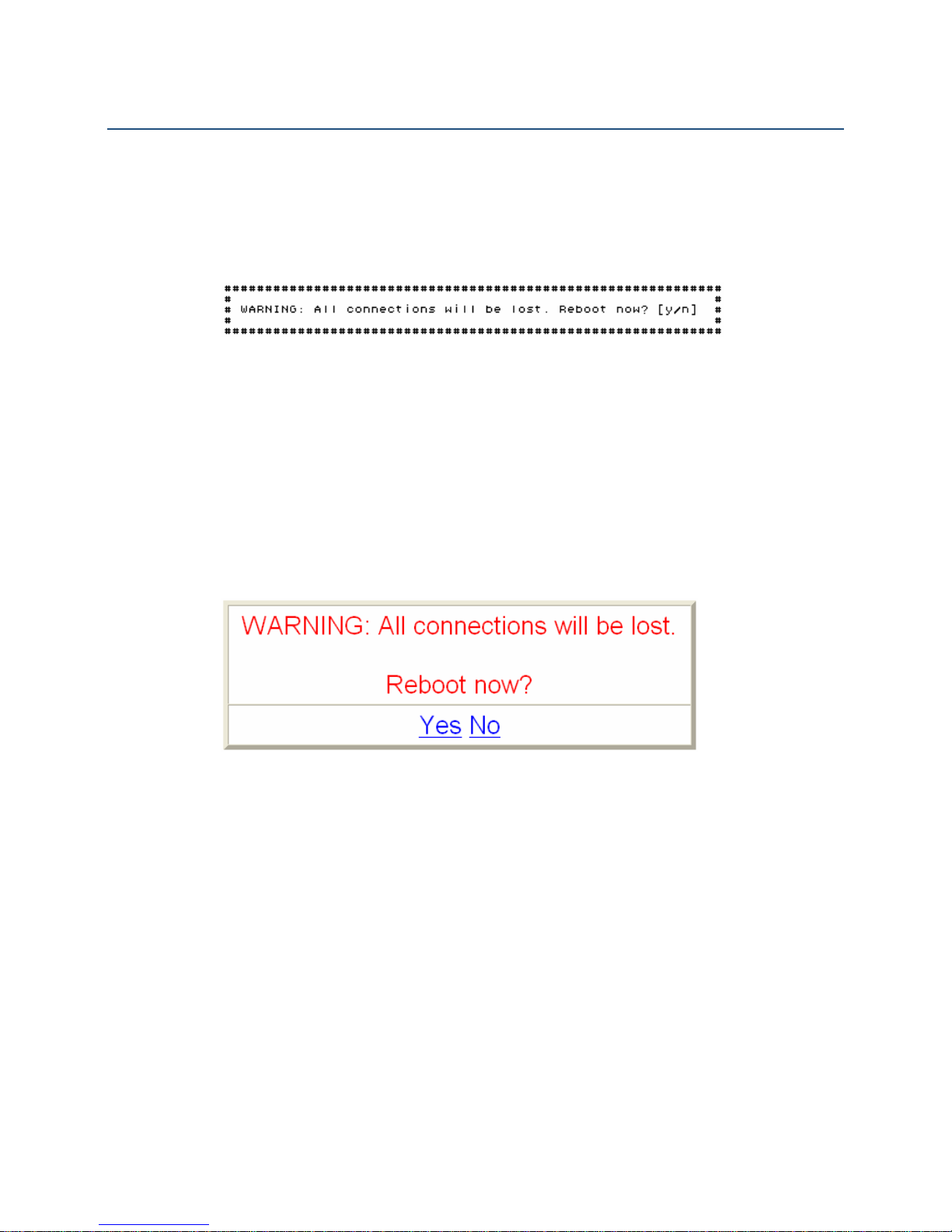
Path: Gateway->Utilities->System->Reboot.
A warning message is displayed and you are asked to confirm the reboot:
Entering “[Y]es” will cause the unit to be rebooted and entering “[N]o” will abort the
operation.
Note: This is a software reboot and will not reset all functionality as would a power cycle
(hard reboot).
29
From the Management Browser
To reboot the system from the Management Browser, go to Gateway->Utilities->System>Reboot
A warning message is displayed and you are asked to confirm the reboot.
Entering “[Y]es” will cause the unit to be rebooted and entering “[N]o” will abort the
operation.
Note: This is a software reboot and will not reset all functionality as would a power cycle
(hard reboot).
Document Number: M-4100-MUC Version: Rev AA © Copyright 2007 Citel plc All Rights Reserved
Page 30

IP Dual Port PBXgateway and Remote System Administrator’s Guide
Essential Configuration - Quick Reference
This section is a quick reference list of the essential configuration steps that must be
performed during the execution of the Setup Wizard and/or after the Setup Wizard has
been run to ensure proper functionality of the units. A full description of the features
described below begins with the Essential Configuration section later in this document.
1. Enable or disable individual ports (disable ports that are not in use).
Path: Gateway (and Remote) ->Configuration->Port->Port_1 (and Port_2)
► Refer to page 33 and page 38 for full details.
2. Set the user IDs for each port to “map” remote users with specific PBX ports.
Path: Gateway (and Remote) ->Configuration->Port->Port_1 (and Port_2) ->User ID
30
► Refer to page
33 and page 38 for full details.
3. Setup voice parameters for all active telephone ports. Also, tune Jitter Delay and
packet size (if necessary) of each port to accommodate the IP network. See
Port Setup
for full details.
Essential
Path: Gateway->Configuration->Port->Port_1 (and Port_2) ->Voice
► Refer to page
33 for full details.
4. The DTMF parameter (Definity PBX only) must be set to deliver the DTMF tones “out-
of-band.” For more details refer to the description outlined in the PBXgateway
Essential Port Setup.
Path: Gateway->Configuration->Port->Port_1 (and Port_2)
► Refer to page 33 for full details.
5. Set the IP Destination address that the Remote will use to connect to the
PBXgateway. This is simply the PBXgateway’s IP address that was set in step 2.
Path: Remote->Configuration->Connect
► Refer to page 39 for full details.
6. Set the IP parameters to allow the PBXgateway and Remote to communicate over the
IP network.
Path: Gateway (and Remote) ->Configuration->IP->LAN->Address
► Refer to page 36 and page 40 for full details.
7. Allow Telnet and FTP access for administrative and upgrade purposes.
Path: Gateway (and Remote) ->Configuration->IP->LAN
► Refer to page 37 and page 41 for full details.
FTP should always be disabled when not performing an upgrade or file transfer to or from
the PBXgateway and/or Remote
8. Enable the Analog Port on the Remote (if equipped), enable or disable the ringing,
enable the Speaker Key (Norstar only) assign a Dial key, a Dial prefix and/or an
emergency dial string. See
Path: Remote->Configuration->Port->Port_1 (and Port_2) ->More
► Refer to page
Document Number: M-4100-MUC Version: Rev AA © Copyright 2007 Citel plc All Rights Reserved
Essential Configuration of the Analog Port for full details.
42 for full details.
Page 31
IP Dual Port PBXgateway and Remote System Administrator’s Guide
Advanced Configuration – Quick Reference
This section is a quick reference list of the additional configuration steps that can be
performed either during the execution of the Setup Wizard or anytime after to improve
system performance. Although not required, the advanced features may be used to assist
with managing the units or trouble shooting voice issues. Please consult the Advanced
Configuration section prior to contacting customer support. A full description of the
features described below begins with the
1. Identify the port by entering a Description for the specific port (typically user’s name).
Path: Gateway (and Remote) ->Configuration->Port->Port_1 (and Port_2)
Advanced Configuration – PBXgateway section.
31
► Refer to page
45 and page 52 for full details.
2. Setup a Connect password to provide a secure connection restricting unauthorized
access to the PBXgateway port from the Remote.
Path: Gateway (and Remote) ->Configuration->Port->Port_1 (and Port_2)
► Refer to page 45 and page 52 for full details.
3. Set Auto-connect to “enabled” for the sets to automatically connect to the
PBXgateway. If the connection to the PBXgateway is lost for any reason the sets will
attempt to automatically re-connect.
Path: Remote->Configuration->Port->Port_1 (and Port_2)
► Refer to page
52 for full details.
4. The Diversion parameter (Ericsson PBX only) is used to enable the PBX feature of
forwarding of all calls when the user disconnects from the PBXgateway.
Path: Remote->Configuration->Port->Port_1 (and Port_2)
► Refer to page 52 for full details.
The Diversion parameter will only be presented if Ericsson is selected as the PBX type.
For a full description of this feature refer to the Ericsson PBX documentation.
5. Enable Active Call Monitoring (Nortel Norstar PBX only) to monitor another station’s
activity (on another call, for example).
Path: Remote->Configuration->Port->Port_1 (and Port_2)->Phone_Features
► Refer to page
6. Configure Line Signaling (Nortel Norstar PBX only) – Used to help eliminate clicking
noise in the audio path on certain installation environments.
Path: Gateway (and Remote) ->Configuration->Port->Port_1 (and Port_2)
► Refer to page 45 and page 52 or full details.
7. Provide a system name making it easier to identify the unit when administering
multiple PBXgateways or multiple Remotes.
Path: Gateway (and Remote) ->Configuration->System
► Refer to page
8. Set the Time and Date to provide accurate time and date stamps for trouble shooting
and system maintenance.
Path: Gateway (and Remote) ->Utilities->System->Set Date
► Refer to page
Document Number: M-4100-MUC Version: Rev AA © Copyright 2007 Citel plc All Rights Reserved
52 or full details.
46 and page 56 for full details.
47 and page 57 full details.
Page 32

IP Dual Port PBXgateway and Remote System Administrator’s Guide
9. Set an Administrator’s password to restrict access to the PBXgateway and Remote
Management Console (MC).
Path: Gateway (and Remote) ->Utilities->System->Set Password
► Refer to page 47 and page 57 full details.
10. The Administrator assigns the IP Address, Subnet Mask and Gateway Address for
each Static Route (if required).
Path: Gateway (and Remote) ->Configuration->IP->Static_Routes
► Refer to page 50 and page 58 full details.
11. The DNS parameter allows the System Administrator to find the PBXgateway by an
assigned name instead of IP address.
Path: Gateway (and Remote) ->Configuration->IP->DNS
32
► Refer to page
51 and page 60 full details.
Document Number: M-4100-MUC Version: Rev AA © Copyright 2007 Citel plc All Rights Reserved
Page 33
IP Dual Port PBXgateway and Remote System Administrator’s Guide
Essential Configuration – PBXgateway
Once the PBXgateway and Remote are connected, the MC (Management Console)
allows for the configuration of the individual ports according to the requirements of the
individual users and any network requirements according to the corporate IT Manager.
The following is a detailed description of the programming areas that would be considered
“essential” to the proper operation of the PBXgateway.
Do NOT connect the PBXgateway to the PBX or connect the digital telephone(s) to
the Remote until the Setup Wizard has been run. An improperly configured
!
Essential Port Setup
PBXgateway can cause damage to the PBX line card and an improperly configured
Remote can cause damage to the digital telephone sets.
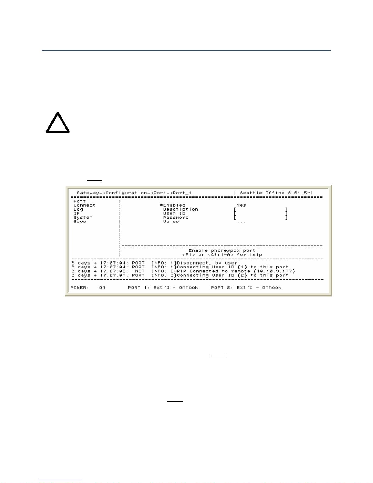
The PBXgateway Port configuration screen is shown below:
Path: Gateway->Configuration->Port->Port_1 (and Port_2)
33
Figure 10: PBXgateway - Port Configuration Screen
1. Port Enabled Yes/No - Disabling any unused ports is recommended in order to
reduce any unnecessary traffic on the network link.
2. Setting User IDs – A user ID “maps” which port on the Remote connects to a specific
port on the PBXgateway. There are several ways in which this is accomplished:
a) By default, Port Matching is enabled (
If no user ID is entered on the Remote the user will be prompted to enter the User
ID when connecting to the PBXgateway (by default it is the PBXgateway port
number). The administrator must advise the users of what number to enter when
connecting (i.e. ‘1’ for port 1, ‘2’ for port 2).
b) User IDs can be manually input either in the individual port menus or by use of
the User List feature (
management of multiple users. The main difference with the User List is that a
user can be assigned multiple ports to connect to (typically not used on a one or
two port system).
c) When using multiple Remotes to connect to a single PBXgateway the User IDs
must be used to specify which user is to connect to which ports on the
PBXgateway. It is recommended that User IDs reflect the user’s extension
Document Number: M-4100-MUC Version: Rev AA © Copyright 2007 Citel plc All Rights Reserved
Path: Gateway->Configuration->Connect).
Path: Gateway->User List). The User list allows for easier
Page 34
IP Dual Port PBXgateway and Remote System Administrator’s Guide
number. For example, if John Smith’s internal extension number was 5637 then
5637 should be used as this port’s User ID on the PBXgateway and Remote.
3. Setting the Voice Parameters – Voice parameters are set on a by-port basis and are
used to “fine tune” voice processing and bandwidth usage. Users will have to
disconnect from the PBXgateway and reconnect for any changes to these parameters
to take affect.
It should be noted that the default settings for the voice parameters are usually sufficient
and should not require adjustment. It is, therefore, recommended that a few “test” calls be
made to identify any voice quality issues prior to configuring the voice parameters. The
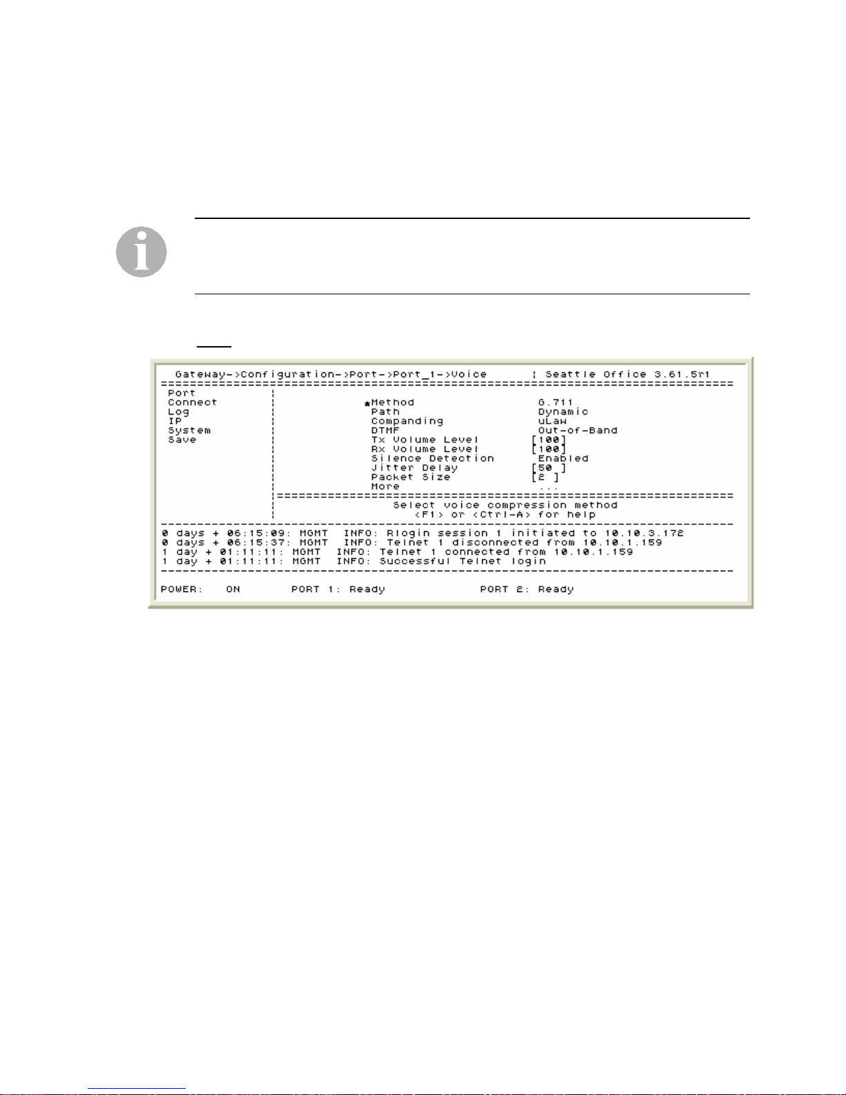
Voice Parameters screen is shown below:
Path: Gateway->Configuration->Port->Port_1 (and Port_2) ->Voice
34
Figure 11: PBXgateway – Voice Configuration Screen
a) Method (of compression) – Selecting different voice compression methods can
reduce network bandwidth requirements. The four methods offered are:
i) ADPCM32 (60Kbps)
ii) ADPCM24 (50Kbps)
iii) G.729A (30Kbps)
iv) G.711 (90Kbps)
It should be noted that a highly compressed voice path can have a negative affect
on voice quality. For example, G.729 is more compressed than G.711 resulting in
less bandwidth usage but this can have an affect on voice quality. See
Calculating Bandwidth Requirements: for calculating bandwidth requirements.
b) Path – Another method of reducing bandwidth is by configuring how the voice
path is allocated. When the path set to Constant the bandwidth is always
available for that port (recommended). When set to Dynamic the bandwidth for
the voice path is allocated only when the user goes offhook to invoke or receive a
call. This is useful if there are restrictions for bandwidth usage. In Dynamic mode
if bandwidth is not available to invoke or receive a call the user will receive an
audible error tone and a visual error message on the telephone.
Document Number: M-4100-MUC Version: Rev AA © Copyright 2007 Citel plc All Rights Reserved
Page 35

IP Dual Port PBXgateway and Remote System Administrator’s Guide
c) Companding – This is a telecommunications standard, by region, for the
transmission of voice. In North America the standard is µLaw (pronounced mu
law) and in Europe the standard is aLaw. When the companding is not set
correctly voice will sound choppy and garbled.
d) DTMF (Definity PBX only) – The PBXgateway must be set to deliver the DTMF
tones either within the voice path (inband) or not within the voice path (out-ofband). This is based on the functionality of the PBX. If the PBXgateway is
configured for the Definity PBX type then DTMF should be set to “out-of-band.”
The DTMF parameter will only appear if the PBX type is set to Definity. If the DTMF value
is not set properly the routing of the Analog port Emergency Number will fail (see
Essential Configuration of the Analog Port on setting up the Analog port).
e) Tx Volume Level – The outgoing volume level of the signal being sent to the PBX
can be adjusted to decrease the amount of echo that may be experienced during
calls in some areas. The transmit level can be adjusted from 25% to 150%.
f) Rx Volume Level - The incoming volume level of the signal being sent to the PBX
can be adjusted to decrease the amount of echo that may be experienced during
calls in some areas. The transmit level can be adjusted from 25% to 150%.
35
g) Silence Detection – When voice is transmitted over the network it is treated as
data. If silence detection is enabled then no “data” is sent across the network
during silent periods of a conversation. This will further assist in reducing
bandwidth usage.
h) Jitter Delay – This is the amount of delay (in milliseconds) in sending voice
packets to account for the “Jitter” in a particular IP network. If not set properly
voice may sound choppy. Increasing the Jitter Delay parameter reduces audible
audio noise and helps prevent this from occurring. The Jitter Delay can be
adjusted from 20 milliseconds (ms) to 250 milliseconds (ms). If required, it is
recommended to begin at 20 to 30 ms when adjusting for network jitter.
Calculating Jitter Delay:
The Jitter Delay should be set to a multiple of the Voice Packet Size Time Equivalent.
This is the amount of time taken, in milliseconds (ms), by the combined voice packets. For
example, if using G.729A, where each voice packet is equivalent to 10ms of time, and you
have a packet size of 2 then the Voice Packet Size Equivalent is 20 ms (2 packets x
10ms).
i) Packet Size – The Packet Size can also be increased to reduce packet loss and
bandwidth requirements but it may cause some additional delays in voice
delivery. It is recommended to leave this at the default value of 2. It may become
necessary to increase this value to 4 for some packet networks or if using a
higher compression such as G.729 (see the Method section in
for more details).
Setup
Essential Port
j) More…->Packet Trace – This is used for trouble shooting purposes only and a
Customer Services representative will instruct the Administrator on how to use
this feature should the need arise.
Document Number: M-4100-MUC Version: Rev AA © Copyright 2007 Citel plc All Rights Reserved
Page 36

IP Dual Port PBXgateway and Remote System Administrator’s Guide
Essential IP Parameters – LAN Address
Prior to the users making any phone calls or the administrator having remote access to
the PBXgateway and Remote the system IP parameters must be configured. The
following is a detailed description of the programming areas that would be considered
“essential” to the proper operation of the PBXgateway and Remote. The PBXgateway
LAN Address configuration screen is shown below:
Path: Gateway->Configuration->IP->LAN->Address
36
Figure 12: PBXgateway – LAN Address Configuration Screen
1. Configuring the unit’s IP Address – A valid IP address for the PBXgateway must be
entered in order for it to operate on the IP network. The IP address should be
obtained from the corporate IT Administrator prior to configuring the PBXgateway.
2. Configuring the Subnet Mask - A valid subnet mask for the PBXgateway must also
be entered in order for it to operate on the IP network. The subnet mask should be
obtained from the corporate IT Administrator prior to configuring the PBXgateway.
3. The Default Router – A valid default router address must be entered to reach IP
hosts not on this same IP sub-network. The default router should be obtained from the
corporate IT Administrator prior to configuring the PBXgateway.
Document Number: M-4100-MUC Version: Rev AA © Copyright 2007 Citel plc All Rights Reserved
Page 37

IP Dual Port PBXgateway and Remote System Administrator’s Guide
Essential IP Parameters – Telnet, Rlogin and FTP
Prior to the users making any phone calls or the administrator having remote access to
the PBXgateway and Remote the system IP parameters must be configured. The
following is a detailed description of the programming areas that would be considered
“essential” to the proper operation of the PBXgateway and Remote. The PBXgateway
Telnet, Rlogin and FTP configuration screen is shown below:
Path: Gateway->Configuration->IP->LAN
37
Figure 13: PBXgateway – Telnet, Rlogin and FTP Configuration Screen
1. Telnet – The PBXgateway can be accessed remotely by use of a standard Telnet
session. By default Telnet is enabled. See
Telnet Connection for more information.
2. Rlogin – The Remote management interface can also be accessed through the
PBXgateway’s Remote Login feature with Rlogin enabled. The Remote Login feature
is found here:
Path: Gateway->Remote Login. For security reasons this feature is
disabled on default.
3. FTP – File Transfer Protocol (FTP) is used primarily during the upgrade process. For
security reasons this feature is disabled on default. FTP should remain disabled when
not upgrading a unit or unless otherwise instructed to by a Customer Support
representative.
An administrator’s password should be set to restrict unauthorized access to the
PBXgateway. Go to the Administrator Password section for details. If the password is lost
or forgotten please contact a customer support representative at 1-877-248-3587 or
[email protected] to reset the unit’s password. Individual port passwords are not
affected.
HE ESSENTIAL CONFIGURATION PARAMETERS FOR THE PBXGATEWAY ARE NOW COMPLETE.
T
PLEASE CONTINUE CONFIGURATION WITH THE REMOTE.
Document Number: M-4100-MUC Version: Rev AA © Copyright 2007 Citel plc All Rights Reserved
Page 38

IP Dual Port PBXgateway and Remote System Administrator’s Guide
Essential Configuration – Remote
Once the PBXgateway and Remote are connected, the MC (Management Console)
allows for the configuration of the individual ports according to the requirements of the
individual users and any network requirements according to the corporate IT Manager.
The following is a detailed description of the programming areas that would be considered
“essential” to the proper operation of the Remote.
Do NOT connect the PBXgateway to the PBX or connect the digital telephone(s) to
the Remote until the Setup Wizard has been run. An improperly configured
!
Essential Port Setup
PBXgateway can cause damage to the PBX line card and an improperly configured
Remote can cause damage to the digital telephone sets.
The Remote Port configuration screen is shown below:
Path: Remote->Configuration->Port->Port_1 (and Port_2)
38
Figure 14: Remote - Port Configuration Screen
4. Port Enabled Yes/No - Disabling any unused ports is recommended in order to
reduce any unnecessary traffic on the network link.\
5. Setting User IDs – A user ID “maps” which port on the Remote connects to a specific
port on the PBXgateway. There are several ways in which this is accomplished:
a) By default, Port Matching is enabled (
If no User ID is entered on the Remote the user will be prompted to enter the
User ID when connecting to the PBXgateway (by default it is the PBXgateway
port number). The administrator must advise the users of what number should be
entered when connecting.
b) User IDs can be manually input either in the individual port menus or by use of
the User List feature (
PBXgateway only) allows for easier management of multiple users. The main
difference with the User List is that a user can be assigned multiple ports to
connect to (typically not used on a one or two port system).
c) When using multiple Remotes to connect to a single PBXgateway the User IDs
must be used to specify which user is to connect to which ports on the
PBXgateway.
Document Number: M-4100-MUC Version: Rev AA © Copyright 2007 Citel plc All Rights Reserved
Path: Gateway->Configuration->Connect).
Path: Gateway->User List). The User List (a function of the
Page 39
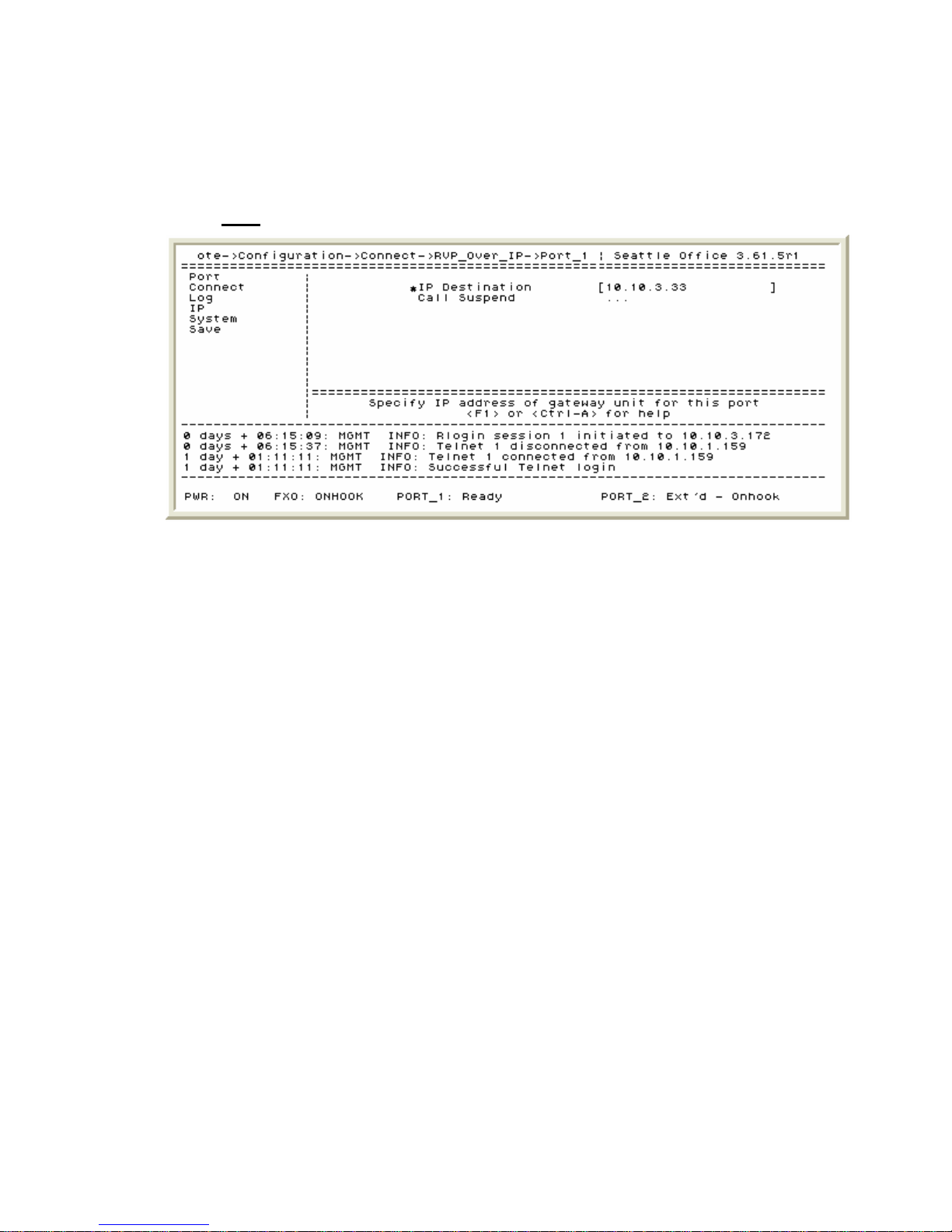
IP Dual Port PBXgateway and Remote System Administrator’s Guide
Essential Connect Parameters
The Connect parameters on the Remote are for configuring the “link” between the Remote
and the PBXgateway. The Connect screen is shown below:
Path: Remote->Configuration->Connect->RVP_Over_IP->Port_1 (and Port_2)
39
Figure 15: Remote – IP Destination Configuration Screen
1. Setting the IP Destination – The IP destination is simply the IP address of the
PBXgateway. The Remote will attempt to connect to the PBXgateway using this
address.
Document Number: M-4100-MUC Version: Rev AA © Copyright 2007 Citel plc All Rights Reserved
Page 40

IP Dual Port PBXgateway and Remote System Administrator’s Guide
Essential IP Parameters – LAN Address
Prior to the users making any phone calls or the administrator having remote access to
the PBXgateway and Remote the system IP parameters must be configured. The
following is a detailed description of the programming areas that would be considered
“essential” to the proper operation of the PBXgateway and Remote. The Remote LAN
Address configuration screen is shown below:
Path: Remote->Configuration->IP->LAN->Address
40
Figure 16: Remote – LAN Address Configuration Screen
1. Setting the Address Mode – In Static mode the Remote will use the IP information
entered in the Address, Subnet Mask and Default Router fields. In DHCP mode
(Dynamic Host Configuration Protocol), if the corporate network is equipped with a
DHCP server, the address will be assigned automatically. The unit’s IP address is
displayed with the system information (
Path: Remote->Status->System->General
Info) and can be viewed at any time.
2. Configuring the unit’s IP Address – A valid IP address for the Remote must be
entered in order for it to operate on the IP network. The IP address should be
obtained from the corporate IT Administrator prior to configuring the Remote.
3. Configuring the Subnet Mask - A valid subnet mask for the Remote must also be
entered in order for it to operate on the IP network. The subnet mask should be
obtained from the corporate IT Administrator prior to configuring the Remote.
4. The Default Router – A valid default router address must be entered to reach IP
hosts not on this same IP sub-network. The default router should be obtained from the
corporate IT Administrator prior to configuring the PBXgateway.
Document Number: M-4100-MUC Version: Rev AA © Copyright 2007 Citel plc All Rights Reserved
Page 41
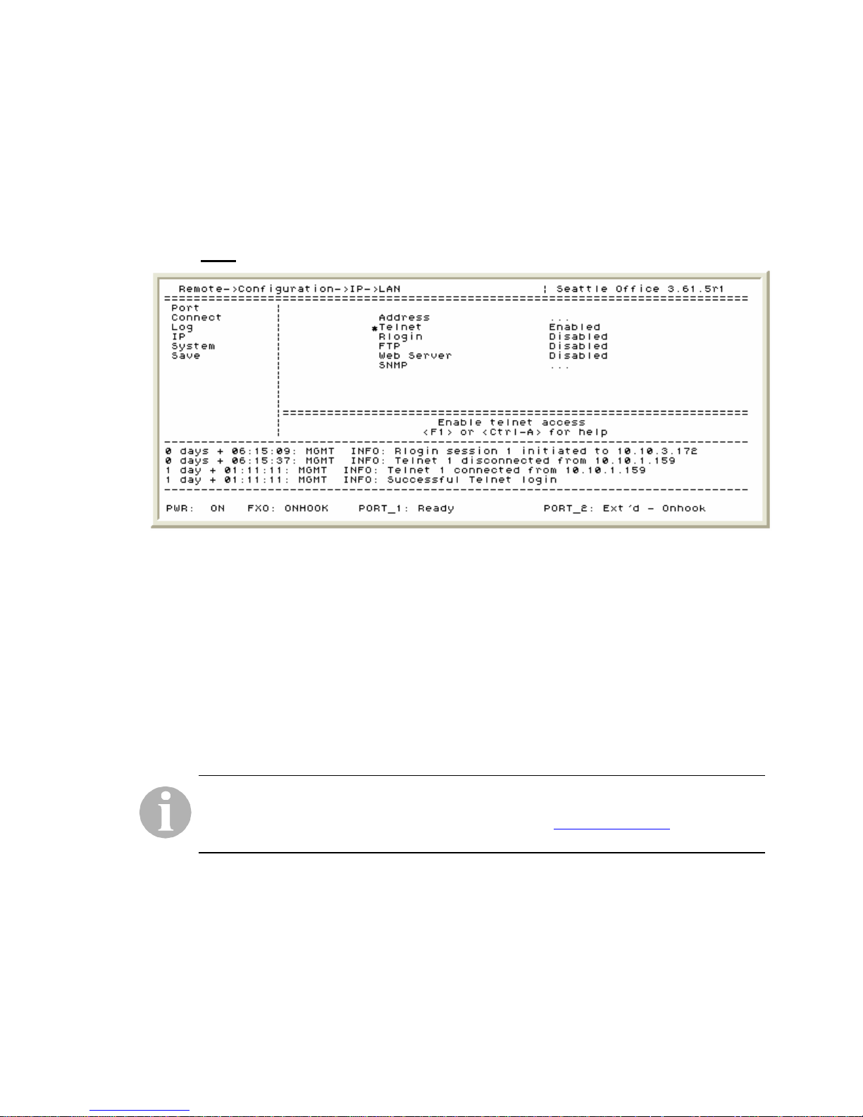
IP Dual Port PBXgateway and Remote System Administrator’s Guide
Essential IP Parameters – Telnet, Rlogin and FTP
Prior to the users making any phone calls or the administrator having remote access to
the PBXgateway and Remote the system IP parameters must be configured. The
following is a detailed description of the programming areas that would be considered
“essential” to the proper operation of the PBXgateway and Remote. The Remote Telnet,
Rlogin and FTP configuration screen is shown below:
Path: Remote->Configuration->IP->LAN
41
Figure 17: Remote – Telnet, Rlogin and FTP Configuration Screen
1. Telnet – The PBXgateway can be accessed remotely by use of a standard Telnet
session. By default Telnet is enabled.
2. Rlogin – The Remote management interface can also be accessed through the
PBXgateway’s Remote Login feature with Rlogin enabled. For security reasons this
feature is disabled on default.
3. FTP – File Transfer Protocol (FTP) is used primarily during the upgrade process. For
security reasons this feature is disabled on default. FTP should remain disabled when
not upgrading a unit or unless otherwise instructed to by a Customer Support
representative.
An administrator’s password should be set to restrict unauthorized access to the Remote.
Go to the Administrator Password for details. If the password is lost or forgotten please
contact a customer representative at 1-877-248-3587 or
[email protected]. Individual
port passwords are not affected.
Document Number: M-4100-MUC Version: Rev AA © Copyright 2007 Citel plc All Rights Reserved
Page 42
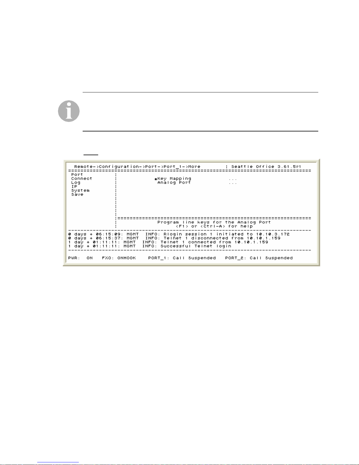
IP Dual Port PBXgateway and Remote System Administrator’s Guide
Essential Configuration of the Analog Port
The Single and Dual Port Remote are both available with an optional analog port for local
dialing. Labeled “Analog” on the back of the Remote, it provides a PSTN (Public Services
Telephone Network) connection to an analog telephone line for the purpose of reaching
local emergency services (fire, police, etc.) or for making local calls. The main Analog port
configuration screen is shown below:
If a user dials emergency services on the digital set at the remote location when the
telephone is connected to the Remote and “linked” to the PBXgateway you will reach the
emergency facility that serves the location of the PBXgateway (corporate facility) and not
the remote location. To ensure that you reach the correct emergency services for your
area, use a telephone and/or line connected locally.
Path: Remote->Configuration->Port->Port_1 (and Port_2) ->More
42
Figure 18: Remote – Analog Port Main Configuration Screen
Document Number: M-4100-MUC Version: Rev AA © Copyright 2007 Citel plc All Rights Reserved
Page 43
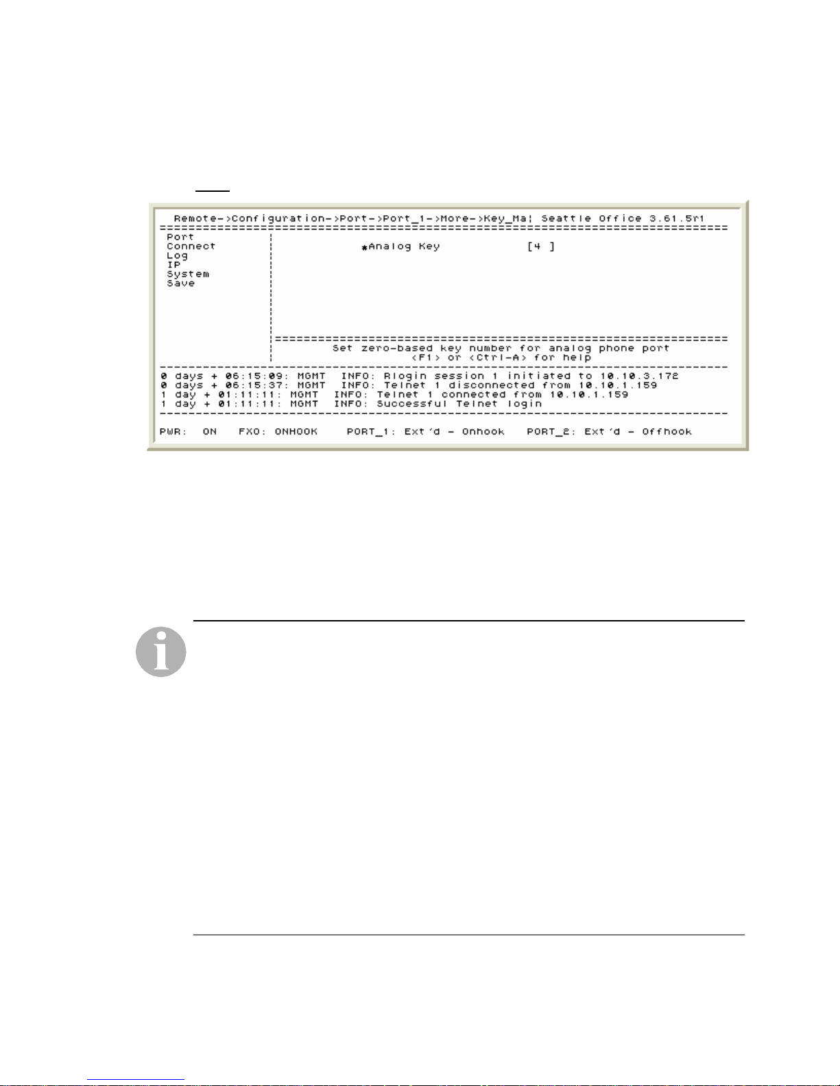
IP Dual Port PBXgateway and Remote System Administrator’s Guide
Within the Key Mapping menu structure is the Analog Key field. The Analog Key field is
programmed with the telephone line key (of the digital set) that will be used to access the
analog line. The Analog Key configuration screen is shown below:
Path: Remote->Configuration->Port->Port_1 (and Port_2) ->More->Key Mapping
43
Figure 19: Remote – Analog Key Configuration Screen
1. Configuring the Analog Key – This is the key the user would press to access the
analog line. Keys 0 to 15 are supported and the default setting is Key 4.
2. Enabling the Speaker Key (Nortel Norstar PBX only) – When set to enabled this
allows for the user to have handsfree operation for the FXO port when not connected
to the PBXgateway.
Operation of the Analog port:
i. If power to the Remote is disrupted the analog line will not be available.
ii. Calls made using the analog port are not routed through the PBXgateway and
subsequently the corporate PBX. Therefore, none of the PBX features will be
available. Only features supplied by the PSTN will be available to the user.
iii. The Analog port can be used whether the network connection is established with the
PBXgateway or not. If the connection is not available the telephone will show
“Press 1 to connect…” and the analog line can be accessed by pressing the
preprogrammed Analog Key on the digital set, pressing the speaker key or by going
offhook.
iv. If the connection to the PBXgateway is established (normal operation) the
telephone set will display the time and date and the analog line can be accessed by
pressing the preprogrammed Analog Key on the digital set, entering the Analog
Dialing Prefix or by dialing the Emergency Number (discussed in detail on the next
page).
The Analog Port configuration menu allows for programming the operational parameters
for the appearance, access and routing of analog calls. The Analog Port configuration
screen is shown on the next page:
Document Number: M-4100-MUC Version: Rev AA © Copyright 2007 Citel plc All Rights Reserved
Page 44
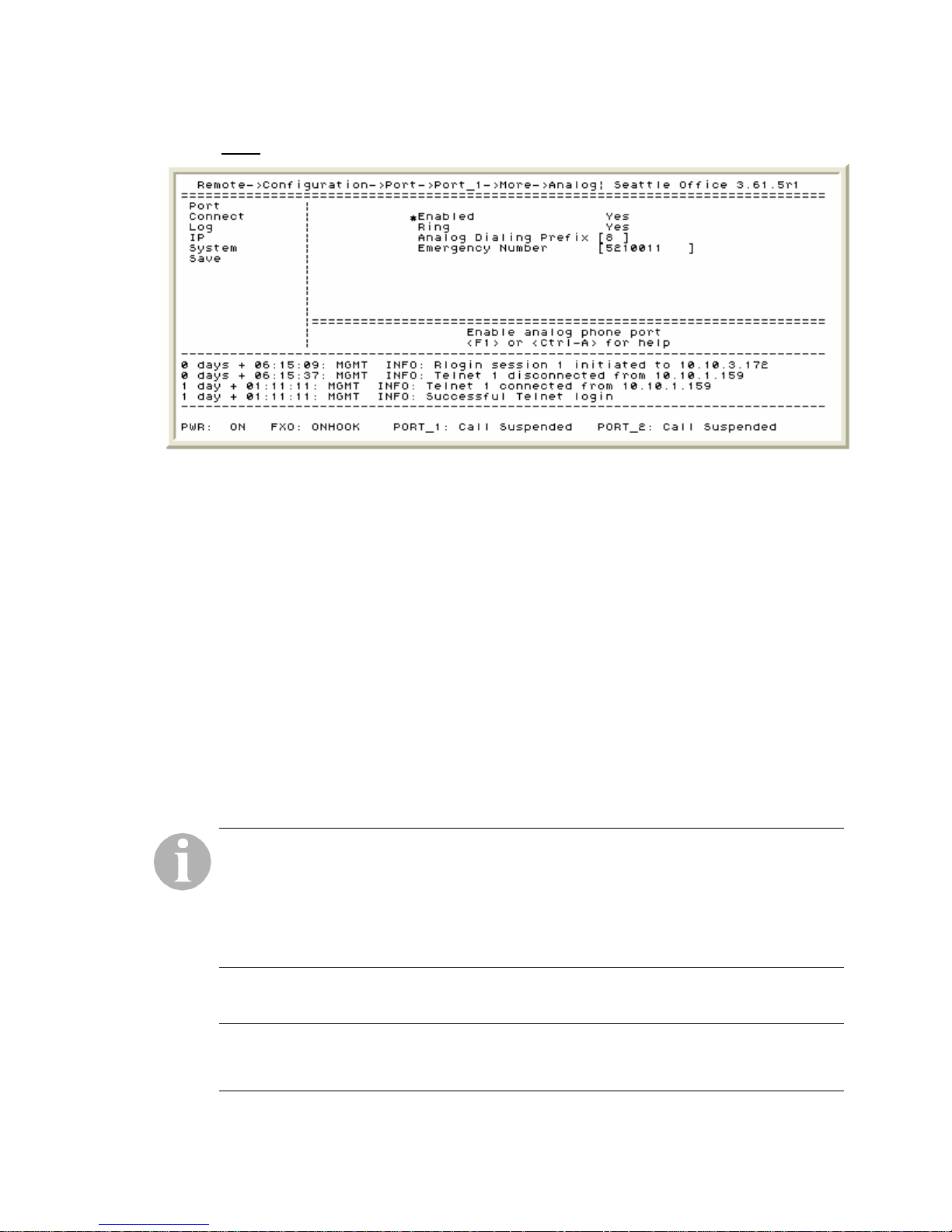
IP Dual Port PBXgateway and Remote System Administrator’s Guide
Path: Remote->Configuration->Port->Port_1 (and Port_2) ->More->Analog Port
Figure 20: Remote – Analog Port Settings Configuration Screen
44
1. Analog port Enabled Yes/No – The analog port is configured separately for the
individual users. ‘Yes’ will enable access to the Analog port and ‘No’ disables it.
2. Setting the Ring preference – The user can have incoming calls to the Analog port
configured to ring or be silent. If Ring is set to ‘No’ then the line indicator will still light
up to indicate a call but it will not have an audible ring.
3. Entering the Analog Dialing Prefix – As with most businesses, to reach an outside
line it’s usually necessary to dial an access code (i.e. 9) and then the number. This is
the same principle as the Dialing Prefix for the analog port. If the user has a telephone
that does not support preprogrammed keys or all the preprogrammed keys are
populated the analog port can be accessed by entering the access code.
4. The Emergency Number – The purpose of the Emergency Number is to route a
predetermined dial string to the Analog port automatically. For example, if the
Emergency Number was 911 (or 999) and the user goes offhook and dials 911 (or
999), this call will be automatically routed to the Analog port and then the call would
be made. Any valid phone number can be used – the phone number to the corporate
main security desk, for example.
If the PBXgateway is connected to an Avaya PBX type it must be set to deliver the DTMF
tones either within the voice path (in-band) or not within the voice path (out-of-band) - this
is based on the functionality of the PBX. If the PBXgateway is configured for Definity then
the DTMF parameter should be set to “out-of-band.” If the DTMF value is not set properly
this will result in routing of the Analog port Emergency Number to fail (refer to
Configuration of the Analog Port
). The DTMF parameter will only appear if the PBX type is
Essential
set to Definity.
HE ESSENTIAL CONFIGURATION PARAMETERS FOR THE REMOTE ARE NOW COMPLETE.
T
PLEASE TEST THE CURRENT CONFIGURATION BY MAKI NG A FEW “TEST” PHONE CALLS PRIOR
TO
GOING ON TO THE ADVANCED CONFIGURATION SECTION.
Document Number: M-4100-MUC Version: Rev AA © Copyright 2007 Citel plc All Rights Reserved
Page 45
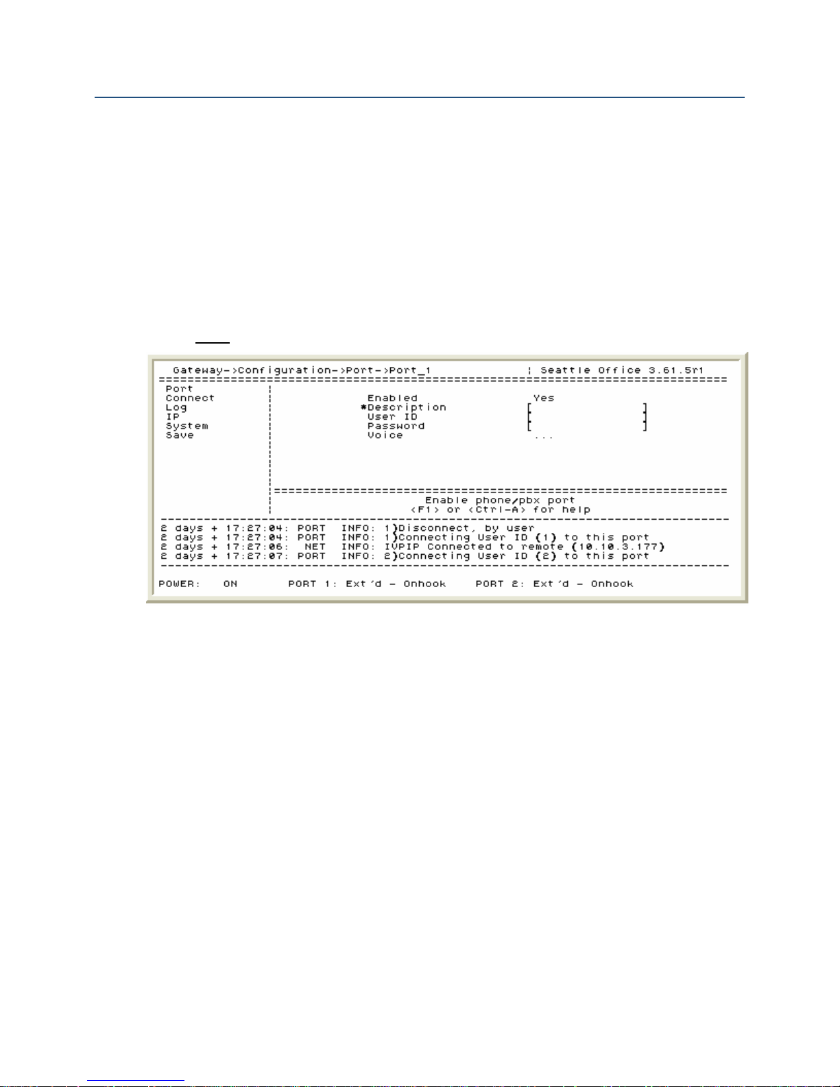
IP Dual Port PBXgateway and Remote System Administrator’s Guide
Advanced Configuration – PBXgateway
Although usually not required, the advanced features may be used to assist with
managing the PBXgateway or trouble shooting voice issues. The following is a detailed
description of the programming areas that would be considered “advanced” to the proper
operation of the PBXgateway. Please consult the Advanced Configuration section prior to
contacting customer support should issues arise.
Advanced Port Setup
The PBXgateway Port configuration screen is shown below:
Path: Gateway->Configuration->Port->Port_1 (and Port_2)
45
Figure 21: PBXgateway – Port Configuration Screen
1. Port Descriptions – The port description accepts 16 characters of text to identify the
user of a specific port. Typically the user’s name would be entered (i.e. John Smith).
2. Setting a Connect Password – A Connect Password restricts access to the telephone
port and is typically used in conjunction with the User ID feature. If the password is set
only on the PBXgateway then the user will have to manually input the password when
connecting. If, however, a password is entered for a port on the PBXgateway and
Remote the user will not be required to take any action.
3. Configuring the Line Signaling (Nortel Norstar PBX only) – On some installation
environments a clicking noise may be present in the audio path. This is caused by
errors in the duty cycle of the signaling wave form. This setting can be adjusted from 0
to 7. Some experimentation may be required to eliminate any audio issues that may
arise.
Document Number: M-4100-MUC Version: Rev AA © Copyright 2007 Citel plc All Rights Reserved
Page 46

IP Dual Port PBXgateway and Remote System Administrator’s Guide
Advanced System Parameters – System Name/Connect Speed
The PBXgateway system configuration screen is shown below:
Path: Gateway->Configuration->System
46
Figure 22: PBXgateway – System Name/Connect Speed Configuration Screen
1. Assigning a system Name – The Name field in the PBXgateway is used for
identification purposes only and appears next to the software revision (see above).
This makes it easier for an administrator when managing multiple sites. Typically the
geographic location of the unit is input “Seattle Office” for example. Any text up to 15
characters can be input in this field.
2. Changing the Console baud – This is the speed at which information is transmitted to
and from the PBXgateway through the console port labeled “COMM” on the back of
the unit. The baud rate can be changed to 2400, 4800, 9600, 19200 or 38400. The
default is 9600.
Document Number: M-4100-MUC Version: Rev AA © Copyright 2007 Citel plc All Rights Reserved
Page 47

IP Dual Port PBXgateway and Remote System Administrator’s Guide
Advanced System Utilities – Time and Date
The PBXgateway utilities configuration screen is shown below:
Path: Gateway->Utilities->System->Set Date
47
Figure 23: PBXgateway – Time and Date Configuration Screen
1. Set Date - Adjust the fields to show the correct time and date.
The Daylight Savings field has been updated to reflect the new DST (Daylight Savings
Time) changes in North America for 2007 as per the Energy Policy Act of 2005.
Document Number: M-4100-MUC Version: Rev AA © Copyright 2007 Citel plc All Rights Reserved
Page 48
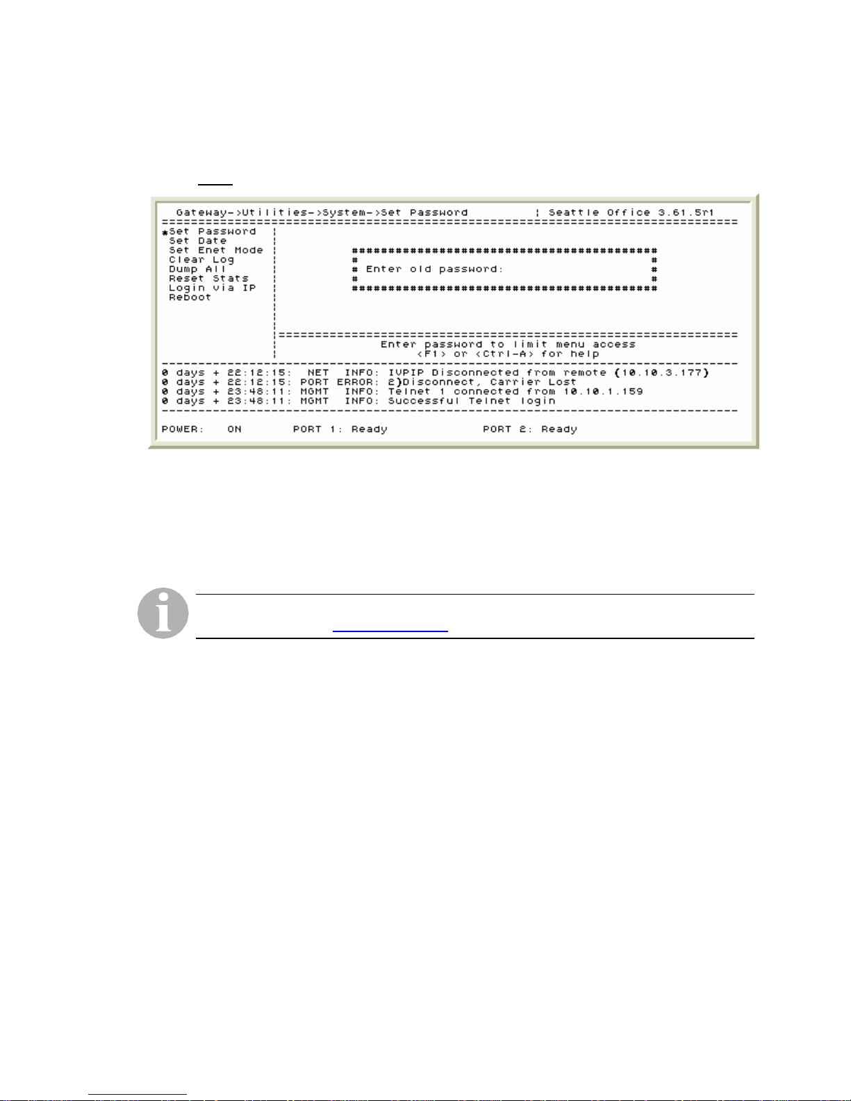
IP Dual Port PBXgateway and Remote System Administrator’s Guide
Advanced System Utilities – Administrator Password
The PBXgateway utilities configuration screen is shown below:
Path: Gateway->Utilities->System->Set Passsword
Figure 24: PBXgateway – Administrator Password Screen
48
1. The Set Password function - The administrator password can be a maximum of 10
digits and it restricts unauthorized access to the Management Console (MC). It is
important to set an administrator password because the unit’s password is blank (no
password) by default. Keep the password in a safe place.
If the unit’s password is lost or forgotten please contact a customer support representative
at 1-877-248-3587 or [email protected]. Individual port passwords are not affected.
Document Number: M-4100-MUC Version: Rev AA © Copyright 2007 Citel plc All Rights Reserved
Page 49

IP Dual Port PBXgateway and Remote System Administrator’s Guide
Advanced IP Parameters – Prioritizing Voice (DiffServ)
The PBXgateway supports the Differential Services packet prioritization protocol. DiffServ
can be chosen to prioritize packets within the network.
All nodes in the network must be configured to prioritize traffic based on DiffServ in order
for this feature to function properly.
The Type of Service configuration field is shown below:
Path: Gateway->Configuration->Connect->RVP_Over_IP
49
Figure 25: PBXgateway – DiffServ
1. Entering the Type of Service – The administrator can enter a type of service value
between 0 and 255. This information should be obtained from the corporate IT
Manager prior to configuring the unit.
More on Differential Services:
Each RVP_Over_IP voice packet contains a Type of Service (ToS) byte. Within this byte
are three bits which are the class of service field. The class of service field is always
automatically set to low delay for RVP_Over_IP voice packets by the EXTender 4100.
Also within the ToS byte are three bits for Differential Services. With the DiffServ
implementation the system administrator is given the option of choosing how the three
DiffServ bits are set. These bits tag the traffic among other packets that have the class of
service field set to a low delay, according to the way the corporate network is configured
for DiffServ traffic.
Document Number: M-4100-MUC Version: Rev AA © Copyright 2007 Citel plc All Rights Reserved
Page 50

IP Dual Port PBXgateway and Remote System Administrator’s Guide
Advanced IP Parameters – Static Routes
Typically, a router uses dynamic routes to learn how to reach network destinations.
Dynamic routes are determined from the information exchanged by the routing protocols
and, as the name implies, these may change as networks conditions change. Static
Routes are used by the router when it does not have a route to a destination that has a
better (lower) preference value, when it cannot determine the route to a destination,
and/or when it is forwarding packets that cannot be routed. The PBXgateway Static
Routes configuration screen is shown below:
Path: Gateway->Configuration->IP->Static_Routes->route_1 (and route_2 to route_10)
50
Figure 26: PBXgateway – Static Routes Configuration Screen
The Administrator assigns the IP Address, Subnet Mask and Gateway Address for
each route. Routes 1 – 10 all have the same menu items.
1. Configuring the static route Address – The IP address(es) should be obtained from
the corporate IT Administrator prior to configuring the PBXgateway.
2. Configuring the Subnet Mask - The subnet mask(s) should be obtained from the
corporate IT Administrator prior to configuring the PBXgateway.
3. The Default Router – The default router(s) should be obtained from the corporate IT
Administrator prior to configuring the PBXgateway.
Document Number: M-4100-MUC Version: Rev AA © Copyright 2007 Citel plc All Rights Reserved
Page 51
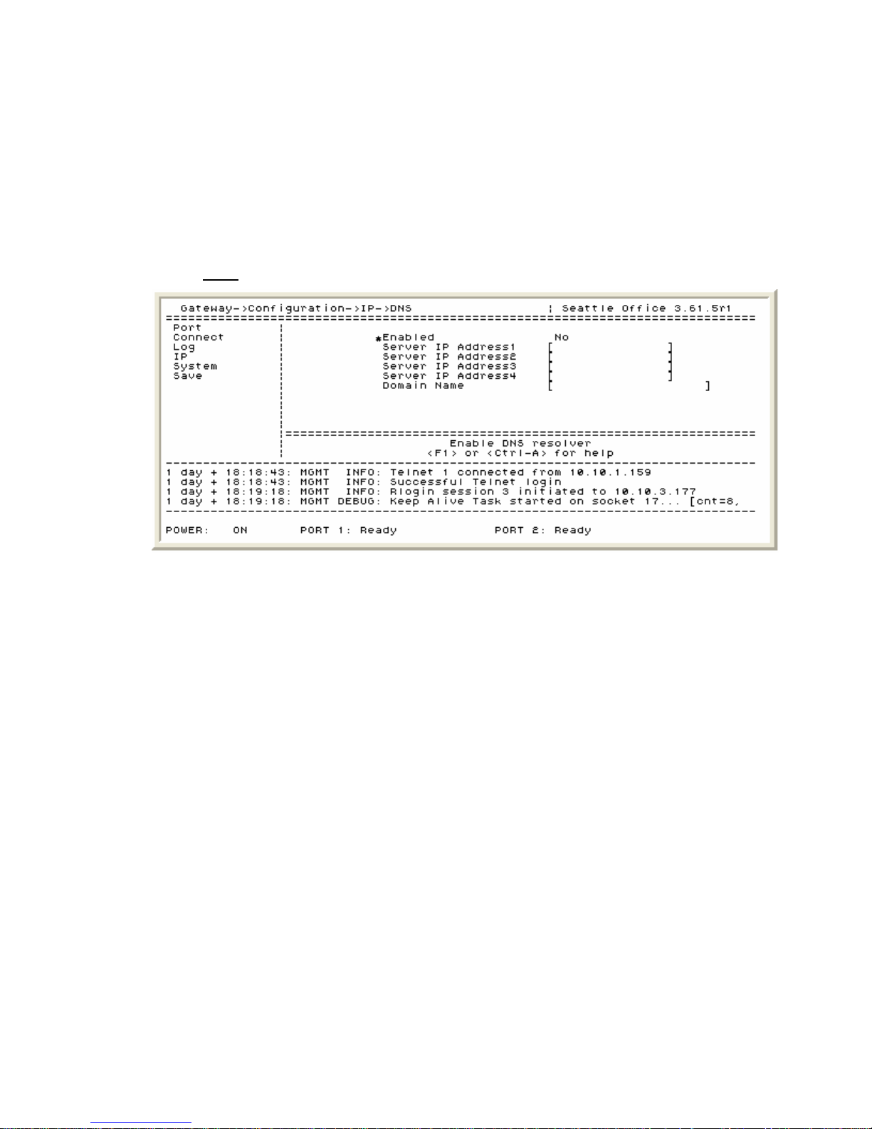
IP Dual Port PBXgateway and Remote System Administrator’s Guide
Advanced IP Parameters – DNS
This parameter allows the System Administrator to find the PBXgateway by an assigned
name. Domain Name Server (DNS) is used in IP networks for translating a host domain
name into an IP address. This information is stored in a DNS server. Enabling DNS on the
PBXgateway allows the System Administrator to search for it by its name and/or IP
address. The DNS parameter is NOT enabled by default. The PBXgateway DNS (Domain
Name Server) configuration screen is shown below:
Path: Gateway->Configuration->IP->DNS
51
Figure 27: PBXgateway – Static Routes Configuration Screen
1. Setting DNS to Enabled – ‘Yes’ will enable DNS and ‘No’ will disable DNS.
2. The Server IP Address1 (to 4) – Enter the address(es) of the DNS servers up to 15
characters. The Server IP addresses should be obtained from the corporate IT
Administrator prior to configuring the PBXgateway.
3. Entering the Domain Name – The domain name (i.e. Citel) is entered in this field to a
maximum of 20 characters. The Domain Name should be obtained from the corporate
IT Administrator prior to configuring the PBXgateway.
Document Number: M-4100-MUC Version: Rev AA © Copyright 2007 Citel plc All Rights Reserved
Page 52

IP Dual Port PBXgateway and Remote System Administrator’s Guide
Advanced Configuration – Remote
Although usually not required, the advanced features may be used to assist with
managing the Remote or trouble shooting voice issues. The following is a detailed
description of the programming areas that would be considered “advanced” to the proper
operation of the Remote. Please consult the Advanced Configuration section prior to
contacting customer support should issues arise.
Advanced Port Setup
The Remote Port configuration screen is shown below:
Path: Remote->Configuration->Port->Port_1 (and Port_2)
52
Figure 28: Remote – Port Configuration Screen
1. Port Descriptions – The port description accepts 16 characters of text to identify the
user of a specific port. Typically the user’s name would be entered (i.e. John Smith).
2. Auto Connect – The Remote ports can be set to auto connect in case of a lost
connection (or “link”) between the PBXgateway and the Remote across the network.
Normally, if the user was not connected the set would display “Press 1 to connect…”
but with auto connect enabled the ports would attempt to connect automatically at
different time intervals. This means that the Remote will wait a few seconds between
tries (up to a maximum of one minute) before it stops attempting to reconnect.
3. Diversion (Ericsson only) – When set at “Enabled” this will tell the PBX to enable the
Diversion feature when the user disconnects from the PBXgateway (at the end of the
business day, for example).
Diversion is a function of the PBX and this field will only be presented when the Remote is
configured for the Ericsson PBX type.
4. Setting a Connect Password – A Connect Password restricts access to the telephone
port and is typically used in conjunction with the User ID feature. If the password is set
only on the PBXgateway then the user will have to manually input the password when
connecting. If, however, a password is entered for a port on the PBXgateway and
Remote the user will not be required to take any action.
Document Number: M-4100-MUC Version: Rev AA © Copyright 2007 Citel plc All Rights Reserved
Page 53

IP Dual Port PBXgateway and Remote System Administrator’s Guide
5. Displaying text using Banner – The Banner field can be used to display simple
messages on a telephone equipped with 2-line display. The text appears when the
user is off-line (not connected to the PBXgateway). Typically, the company name is
displayed. A maximum of 15 characters can be entered in this field.
6. Configuring the Line Signaling (Nortel Norstar PBX only) – On some installation
environments a clicking noise may be present in the audio path. This is caused by
errors in the duty cycle of the signaling wave form. This setting can be adjusted from 0
to 7. Some experimentation may be required to eliminate any audio issues that may
arise.
7. Enabling Active Call Monitoring (Nortel Norstar PBX only) – If the user is monitoring
another station for call activity this should be set to Enabled.
53
Document Number: M-4100-MUC Version: Rev AA © Copyright 2007 Citel plc All Rights Reserved
Page 54

IP Dual Port PBXgateway and Remote System Administrator’s Guide
Advanced Call Suspend Setup
The Call Suspend feature allows for the administrator to reduce IP traffic across the
network by bringing down the IP connection temporarily when all ports are inactive for a
configurable period of time. When the Timeout value is reached, the phones will display
“Suspended” and Management Console (MC) will show the port status as “Call
Suspended” signifying that they are in the Call Suspend mode. Whenever a user goes offhook or an incoming call occurs, the IP connection is restored and all phones are taken
out of Call Suspend mode. The Call Suspend screen is shown below:
Path: Remote->Configuration->Connect->RVP_Over_IP->Port_1 (and Port_2) >Call_Suspend
54
Figure 29: Remote – Call Suspend Configuration Screen
1. Setting Call Suspend to Enabled – When set to “Enabled” the Remote will enter the
Call Suspend mode at the configured time.
2. Entering the Timeout value – A timeout can be configured to allow the administrator
to set when the ports will fall in to Call Suspend. Typically, at the end of the business
day. The timeout can be set for between 5 and 240 minutes.
3. Configuring the Minimum Connect Time – A minimum connect time can also be
programmed to ensure that the connection to the PBXgateway will remain connected
for a specified period of time prior to falling in to Call Suspend mode. The minimum
connect time can be set for between 0 and 240 minutes.
Timeout vs. Minimum Connect Time:
For example, when the user initially connects by pressing “1” on the digital set connected
to the Remote the port will fall into Call Suspend mode at the Minimum Connect Time. If,
however, the user invokes or receives a call that is longer that the Minimum Connect Time
value the port will fall into Call Suspend mode at the Timeout value.
4. Setting for Remote Wakeup Only - If enabled, only activity at the Remote side will
wake the system from Call Suspend (going offhook, for example). This ensures that
any calls placed after hours to the corporate office will not cause the IP link to be reestablished.
Document Number: M-4100-MUC Version: Rev AA © Copyright 2007 Citel plc All Rights Reserved
Page 55

IP Dual Port PBXgateway and Remote System Administrator’s Guide
5. Setting the monitoring Mode – There are three activities that can trigger the system to
wake from Call Suspend:
a) Ring Mode – If ringing is detected on the port it will wake from Call Suspend.
b) Lamp Mode – If lamp activity is detected on the port it will wake from Call
Suspend (Indicators must also be configured – see below)
c) Voice Mode – If a voice call is detected on the port it will wake from Call Suspend.
6. Configuring the Indicators – Used in conjunction with Lamp Mode (above), these are
the line keys that will be monitored. If activity is detected on these configured line keys
the port will wake from Call Suspend mode.
7. Waking on ACD Tone – For use with Automatic Call Distribution systems, set to ‘Yes’
this will allow for an ACD tone to be presented when waking from Call Suspend mode
by an incoming call.
55
Document Number: M-4100-MUC Version: Rev AA © Copyright 2007 Citel plc All Rights Reserved
Page 56
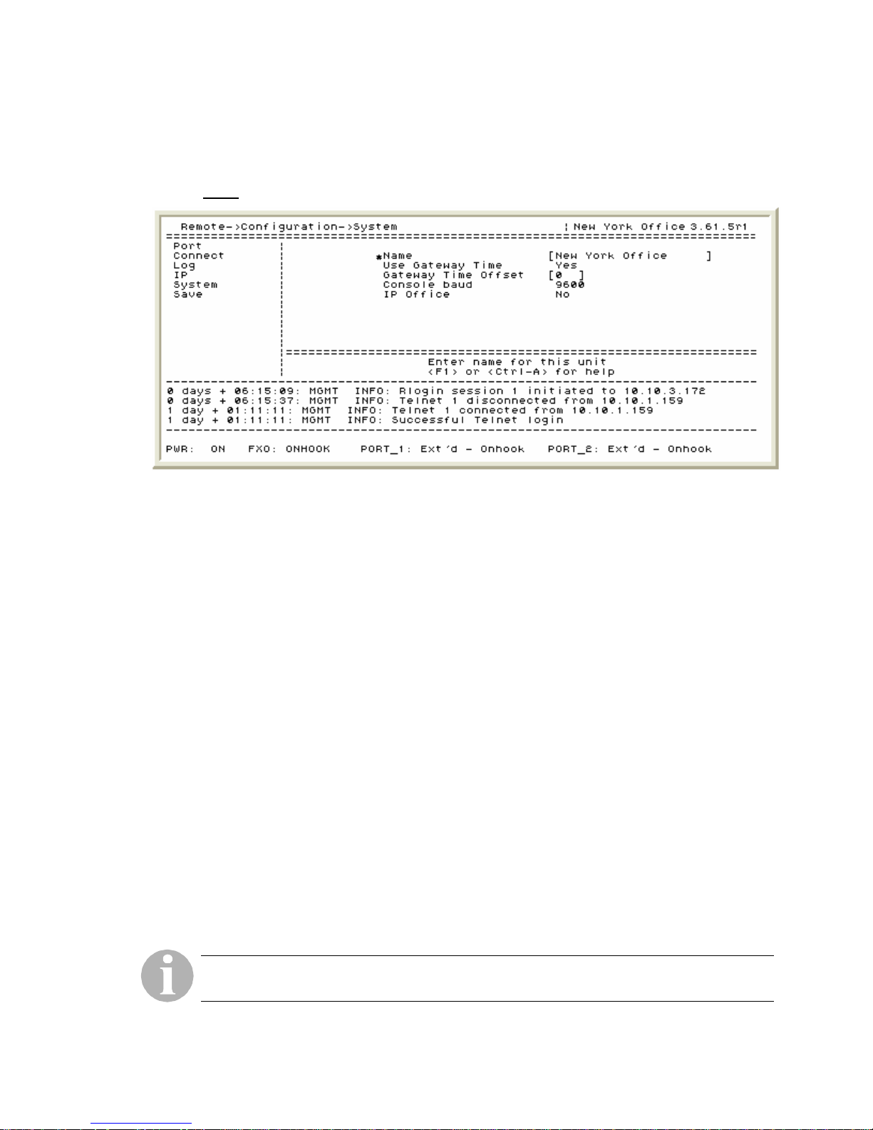
IP Dual Port PBXgateway and Remote System Administrator’s Guide
Advanced System Parameters – System Settings
The Remote system configuration screen is shown below:
Path: Remote->Configuration->System
56
Figure 30: Remote – System Settings Configuration Screen
1. Assigning a system Name – The Name field in the Remote is used for identification
purposes only and appears next to the software revision (see above). This makes it
easier for an administrator when managing multiple sites. Typically the geographic
location of the unit is input “New York Office” for example. Any text up to 15
characters can be input in this field.
2. Configuring to Use Gateway Time – The log files for the Remote can be stamped
using the locally configured time (see
Advanced System Utilities – Time and Date for
time and date configuration) or by using the PBXgateway time. Using the
PBXgateway time is recommended so that time events recorded are consistent at
both the corporate facility and the remote site. This feature will assist during trouble
shooting should the need arise.
3. Setting the Gateway Time Offset – Enter a value that represents the time difference
between the PBXgateway and the Remote. This is used to compensate for the time
difference between cities. For example, if the PBXgateway is at a corporate office in
Seattle and the Remote is at a branch office in New York set this value to +3. This
ensures that the log time stamp and the telephone display use the correct time.
4. Changing the Console baud – This is the speed at which information is transmitted to
and from the PBXgateway through the console port labeled “COMM” on the back of
the unit. The baud rate can be changed to 2400, 4800, 9600, 19200 or 38400. The
default is 9600.
5. Enabling for IP Office (Definity and Magix only) – If telephone sets normally used for
Avaya IP Office are used on the system when it is configured for the Definity or Magix
PBX type then the IP Office parameter must be set to ‘Yes’. Refer to
Supported Telephones – Definity, Magix and IP Office
The IP Office field will only be presented when the Remote is configured for the Definity or
Magix PBX types.
Document Number: M-4100-MUC Version: Rev AA © Copyright 2007 Citel plc All Rights Reserved
Table 15:
for more information.
Page 57

IP Dual Port PBXgateway and Remote System Administrator’s Guide
Advanced System Utilities – Time and Date
The Remote utilities configuration screen is shown below:
Path: Remote->Utilities->System->Set Date
57
Figure 31: Remote – Time and Date Configuration Screen
1. Set Date - Adjust the fields to show the correct time and date.
The Daylight Savings field should be left at ‘disabled’ as this feature has not been updated
to reflect the new DST (Daylight Savings Time) changes for 2007.
Document Number: M-4100-MUC Version: Rev AA © Copyright 2007 Citel plc All Rights Reserved
Page 58
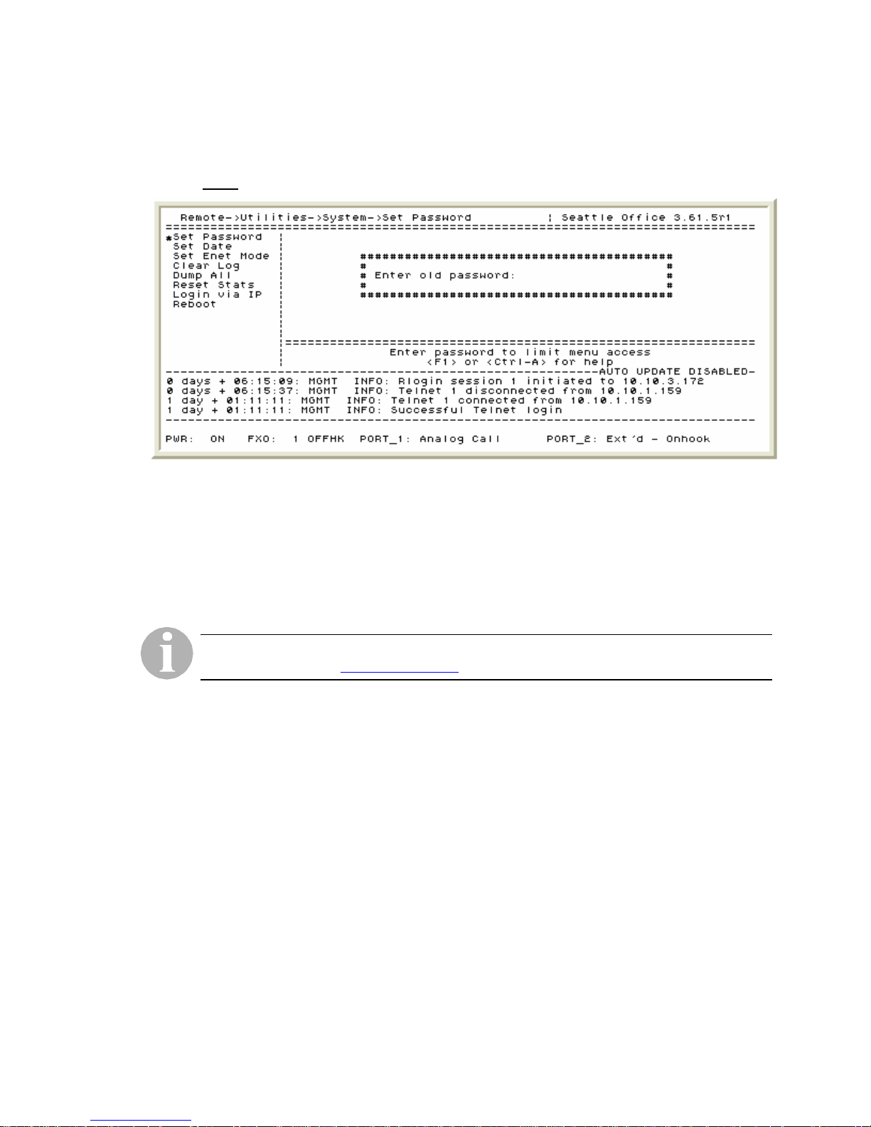
IP Dual Port PBXgateway and Remote System Administrator’s Guide
Advanced System Utilities – Administrator Password
The Remote utilities configuration screen is shown below:
Path: Remote->Utilities->System->Set Password
Figure 32: Remote – Administrator Password Configuration Screen
58
1. The Set Password function - The administrator password can be a maximum of 10
digits and it restricts unauthorized access to the Management Interface (MI). It is
important to set an administrator password because the unit’s password is blank (no
password) by default. Keep the password in a safe place.
If the unit’s password is lost or forgotten please contact a customer support representative
at 1-877-248-3587 or [email protected]. Individual port passwords are not affected.
Document Number: M-4100-MUC Version: Rev AA © Copyright 2007 Citel plc All Rights Reserved
Page 59

IP Dual Port PBXgateway and Remote System Administrator’s Guide
Advanced IP Parameters – Static Routes
Typically, a router uses dynamic routes to learn how to reach network destinations.
Dynamic routes are determined from the information exchanged by the routing protocols
and, as the name implies, these may change as networks conditions change. Static
Routes are used by the router when it does not have a route to a destination that has a
better (lower) preference value, when it cannot determine the route to a destination,
and/or when it is forwarding packets that cannot be routed. The Remote Static Routes
screen is shown below:
Path: Remote->Configuration->IP->Status_Routes->route_1 (and route_2 to route_10)
59
Figure 33: Remote – Static Routes Configuration Screen
The Administrator assigns the IP Address, Subnet Mask and Gateway Address for
each route. Routes 1 – 10 all have the same menu items
1. Configuring the static route Address – The IP address(es) should be obtained from
the corporate IT Administrator prior to configuring the Remote.
2. Configuring the Subnet Mask - The subnet mask(s) should be obtained from the
corporate IT Administrator prior to configuring the Remote.
3. The Default Router – The default router(s) should be obtained from the corporate IT
Administrator prior to configuring the Remote.
Document Number: M-4100-MUC Version: Rev AA © Copyright 2007 Citel plc All Rights Reserved
Page 60
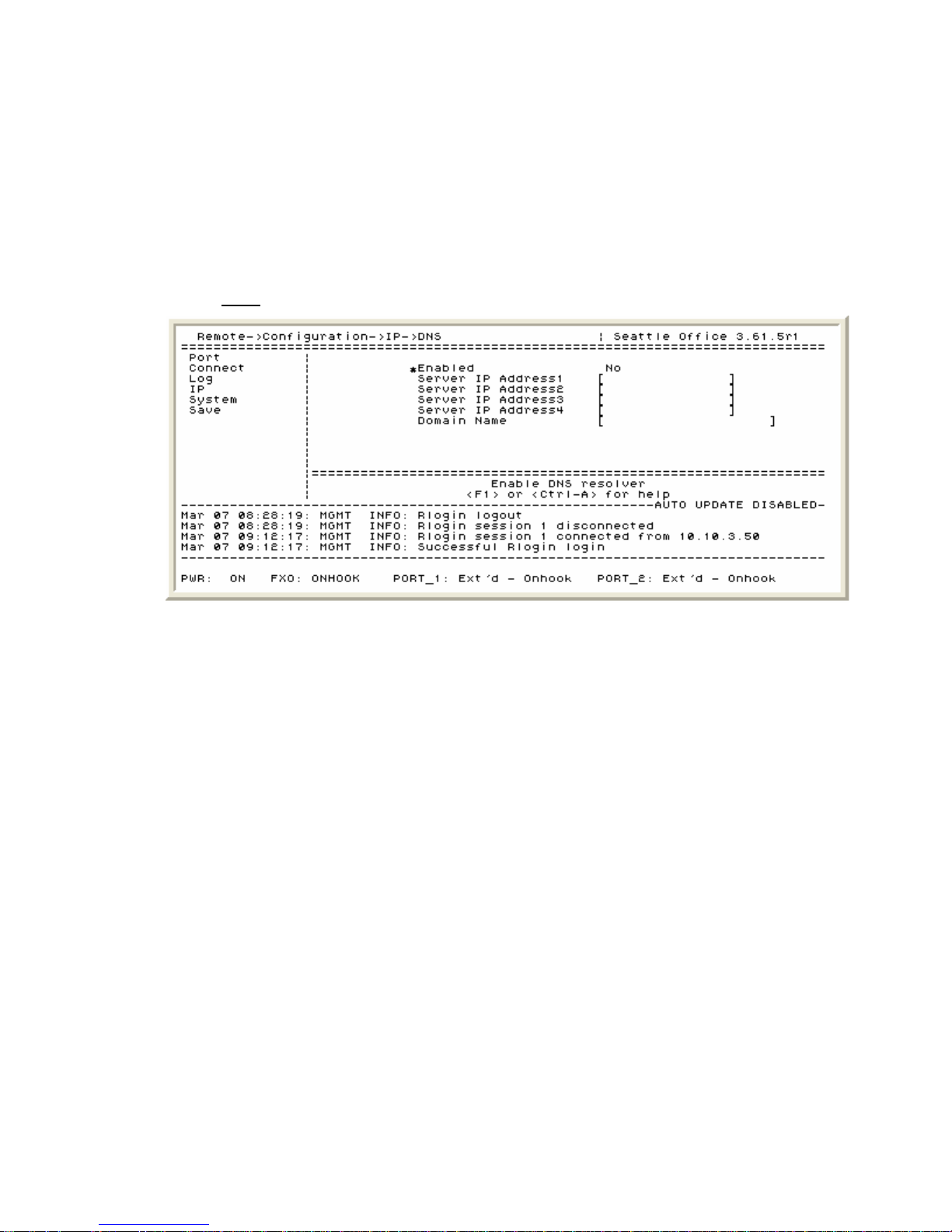
IP Dual Port PBXgateway and Remote System Administrator’s Guide
Advanced IP Parameters – DNS
This parameter allows the System Administrator to find the Remote by an assigned name.
Domain Name Server (DNS) is used in IP networks for translating a host domain name
into an IP address. This information is stored in a DNS server. Enabling DNS on the
Remote allows the System Administrator to search for it by its name and/or IP address.
The DNS parameter is NOT enabled by default. The Remote DNS (Domain Name Server)
configuration screen is shown below:
Path: Remote->Configuration->IP->DNS
60
Figure 34: Remote – DNS Configuration Screen
1. Setting DNS to Enabled – ‘Yes’ will enable DNS and ‘No’ will disable DNS.
2. The Server IP Address1 (to 4) – Enter the address(es) of the DNS servers up to 15
characters. This information should be obtained from the company IT Administrator
prior to configuring the unit.
3. Entering the Domain Name – The domain name (i.e. Citel) is entered in this field to a
maximum of 20 characters. This information should be obtained from the company IT
Administrator prior to configuring the unit.
Document Number: M-4100-MUC Version: Rev AA © Copyright 2007 Citel plc All Rights Reserved
Page 61
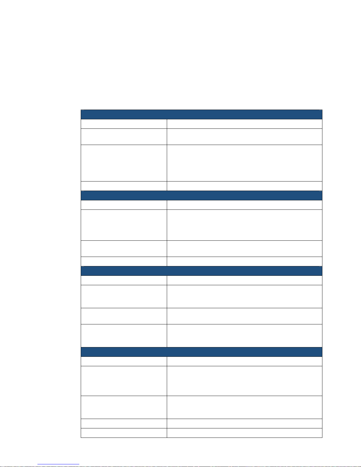
IP Dual Port PBXgateway and Remote System Administrator’s Guide
6 OTHER MI PARAMETERS
This chapter discusses background information for other parameters within the
Management Console (MC). These parameters are primarily used during trouble shooting
and the administrator would be instructed by a Customer Support representative on their
usage. The optional parameters are listed in alphabetical order.
Begin Test (IP)
Path Gateway (Remote) ->Utilities->Diagnostics->Test IP
Description
Usage
Dependencies
Clear Log
Path Gateway (Remote) ->Utilities->System
Description
Usage
Dependencies
Dump All
Path Gateway (Remote) ->Utilities->System
Description
Usage
Dependencies
Edit Config
Path Gateway (Remote) ->Utilities->File
Description
Usage
Dependencies Must use the correct file type (i.e. runtime.cfg)
A test that can be performed that ensures IP
communication is working correctly.
Same as the MS-DOS “Ping” command, it sends packets
back and forth to the unit specified by the IP Address
parameter field (directly below the Begin Test
parameter). After the test is complete messages
describing the results will be presented
none
Clears the log buffer of events on the PBXgateway
and/or the Remote.
WARNING: Clearing the log cannot be undone.
Messages are permanently removed.
Used during trouble shooting. It clears the log of any
unnecessary log messages when tracking issues.
none
This parameter will “dump” the entire log file to the
screen to allow a terminal emulation program (i.e.
HyperTerminal) to capture the text.
Allows the administrator to capture logs and system
information should an anomaly occur.
A VT100 terminal emulation program on a PC must be
running and have the capability of transferring the data
to a text file.
This is a file saved within the flash file system. It contains
all the configuration parameters of the Management
Console (MC). Changes can be saved without affecting
the currently running software image.
Used for managing multiple sites. The same
configuration file can be transferred to different units if
the programming is consistent between devices.
61
Document Number: M-4100-MUC Version: Rev AA © Copyright 2007 Citel plc All Rights Reserved
Page 62

IP Dual Port PBXgateway and Remote System Administrator’s Guide
Optimize
Path Gateway (Remote) ->Utilities->File
Gateway (Remote) ->Utilities->Upgrade
Description
This will “clean up” the internal flash file system for
improved performance.
Usage
Should be executed prior to performing a software
upgrade or for advanced trouble shooting.
WARNING: Do not execute on an active system. This
may cause the flash file system to become corrupt
rendering the PBXgateway or Remote inoperable.
Dependencies
none
Priority (Log)
Path Gateway (Remote) ->Configuration->Log
Description
Allows for the selection of what log types will be
displayed first in the log file.
Usage
Used during trouble shooting. The log message priority
can be customized for the level of troubleshooting
desired.
Log message priorities include:
62
Fatal: Unit is not functioning
Error: Failure
Warning: Problem with unit but still operational
Info: Remote session, someone connected
Debug: Detailed message
Trace: Packet type tracing
For example, if the log priority is set to Info, then the only
log messages that would not be saved are the Debug
and Trace messages
Dependencies
none
Reset Stats
Path Gateway (Remote) ->Utilities->System
Description Rests all the system statistical information.
Usage
Used to “clean up” the system statistics and to help
pinpoint problems should they occur.
Dependencies
none
Size (Log)
Path Gateway (Remote) ->Configuration->Log
Description
When the log file becomes full the log messages
become overwritten by new messages. The
administrator has the ability to increase the log size if
required. Accepted log file sizes are 4096 to 131072.
Usage Limits or increases the number of log messages.
Dependencies
Table 3: Other IP Parameters
none
Document Number: M-4100-MUC Version: Rev AA © Copyright 2007 Citel plc All Rights Reserved
Page 63

IP Dual Port PBXgateway and Remote System Administrator’s Guide
7 CALCULATING BANDWIDTH
REQUIREMENTS:
An important factor in the successful installation and administration of the PBXgateway
and Remote is determining the necessary bandwidth required. Determining the
appropriate amount of bandwidth is a function of two factors:
Number of users (telephones)
Voice compression required for each user
Determining the Number of Users
The number of users is simply the number of telephones that will be “extended” at the
remote site. In the case of the Remote there can be one or two users per device.
63
Determining Voice Compression
The PBXgateway provides various voice compression methods (CODECs). The method
chosen will determine the amount of bandwidth required. The total bandwidth required,
including overhead, depends upon the compression method being used:
Compression Bandwidth per Telephone
G.729A 30 Kbps
ADPCM24 50 Kbps
ADPCM32 60 KBPS
G7.11 90 Kbps
Table 4: Determining Voice Compression
The total amount of bandwidth required for the PBXgateway and Remote application can
be determined by using the
Selecting a Compression Method
Optimum voice quality is achieved when using the G7.11 voice compression method.
However, the high voice quality requires the largest amount of bandwidth due to the low
compression.
Bandwidth Management Formula on the next page.
The highest voice compression is achieved using G.729A. With this voice compression
method the voice quality is considered “near toll” and the bandwidth requirements are
significantly reduced.
If conversation quality is a high priority and bandwidth is not a factor then G.711 or
ADPCM32 would be recommended. If, however, bandwidth is a factor and voice quality is
not paramount then G.729A or ADPCM24 is recommended.
Document Number: M-4100-MUC Version: Rev AA © Copyright 2007 Citel plc All Rights Reserved
Page 64

IP Dual Port PBXgateway and Remote System Administrator’s Guide
Bandwidth Management Formula
If different voice compression methods are required for each port being extended the
following formula will assist in calculating the required bandwidth:
(A x 30) + (B x 50) + (C x 60) + (D x 90) = E
where:
A = number of ports using G.729A
B = number of ports using ADPCM32
C = number of ports using ADPCM24
D = number of ports using G.711
E = total bandwidth required
64
Document Number: M-4100-MUC Version: Rev AA © Copyright 2007 Citel plc All Rights Reserved
Page 65

IP Dual Port PBXgateway and Remote System Administrator’s Guide
8 USING SNMP
The PBXgateway and Remote support Simple Network Management Protocol (SNMP) for
ease of monitoring multiple installations. A third party software application is required to
be operating on the network administrator’s workstation in order to monitor and review the
SNMP traps.
SNMP: The network management architecture used for managing virtually any
network type including TCP/IP, IPX and others. SNMP operates on top of the Internet
Protocol and its purpose for the PBXgateway and Remote is to flag error or failure
conditions and automatically notify the administrator.
Trap: The SNMP mechanism permitting a device to send an alarm to the
administrator’s work station.
MIB: The administrator must load an MIB file (Management Information Base) to
properly monitor the PBXgateway and/or the Remote. This file contains numerous
tables (see next page) based on the Management Console status tables and provides
information such as error counts and the on/off status of the units.
rd
3
Party Software Application: An application such as HP
equivalent) that is installed on the administrator’s workstation that is used to view and
monitor all of the SNMP traps.
®
Openview (or
65
Document Number: M-4100-MUC Version: Rev AA © Copyright 2007 Citel plc All Rights Reserved
Page 66

IP Dual Port PBXgateway and Remote System Administrator’s Guide
MI Status Menu vs. MIB Group Table
MI Status Menu MI Group Table
66
Figure 35: MI Status Menu vs. MIB Table
This is an example of the MIB files internal group, in this case it’s the extInfoTable. A few
of the status items are highlighted to demonstrate how they coincide with the MIB file
when monitoring the PBXgateway and/or Remote.
Document Number: M-4100-MUC Version: Rev AA © Copyright 2007 Citel plc All Rights Reserved
Page 67

IP Dual Port PBXgateway and Remote System Administrator’s Guide
Major Groups of the Remote MIB
MIB Group Management Interface (MI) Menu
extSystemGroup Status->System->General Info
extInfoTable Status->Connect->Connect Info
extStatisticsTable Status->Connect->Connect Stats
extPortStatTable Status->Port
extDiagnosticTable Status-> System->HW Diagnostics
extPortTable Status->Port->Port Stats
extAlarmNotificationGroup The “LOG messages” that appear in the LOG.
extSnmpControlGroup Configuration->IP
extTopologyGroup Defines product relationships
extSuspendTable Call Suspend information, if available.
extRVPOverIPGroup Remote->Config->Connect->RVPoverIP
Table 5: MIB Group vs. MI Menus
67
Document Number: M-4100-MUC Version: Rev AA © Copyright 2007 Citel plc All Rights Reserved
Page 68

IP Dual Port PBXgateway and Remote System Administrator’s Guide
MIB Group Tables
Group Name: extSystemGroup
extHardwareType Indicates if unit is “Switch (Gateway)” or “Remote”.
extSystemName Name specified in the “Configuration->System” menu.
extSerialNumber Serial number of unit.
extTimeBooted Time that the unit was last booted.
extIPAddress The IP address of the unit.
extMACAddress The MAC address of the unit.
extRuntimeVersion The version of software that is running.
extPLDVersion Version of PLD.
extSignalDSPVersion Version of Signal DSP.
extVoiceDSPVersion Version of Voice DSP.
extFlashVersion Version of FLASH.
extROMVersion Version of ROM.
extHardwareVersion Version of Hardware.
extSerialPorts Number of serial ports.
extPhonePorts Number of digital telephone ports.
extDRAM Size of DRAM.
extHeap Size of HEAP.
extFlash Size of FLASH.
68
Group Name: extInfoTable
extInfoPort Ports 1-2.
extInfoCurrentState State of port: UP, RD, NC, XX, VC, AN, CS
extInfoDuration The duration in current state.
extInfoExtended Indicates if port is extended.
extInfoOffHook Indicates ports offhook.
extInfoVoice The compression algorithm used.
extInfoLostSignal Amount of Lost Signal errors.
extInfoV42Resync Number of V42 Resync errors.
extInfoV42FarResync Number of V42 FarResync errors.
extInfoV42Retries Number of V42 Retry errors.
extInfoV42Timeouts Number of V42 Timeout errors.
Group Name: extStatisticsTable
extStatConnectTries Amount of connect attempts.
extStatConnections Amount of successful connections.
extStatByUser Amount of Disconnects by User.
extStatCarrierLost Amount of Disconnects from Lost Carrier.
extStatPortOffline Amount of Disconnects from port being offline.
extStatPortInUse Amount of Disconnects because port was in use.
extStatNoVoice
Amount of Disconnects because there was no Voice Path (no
bandwidth).
Document Number: M-4100-MUC Version: Rev AA © Copyright 2007 Citel plc All Rights Reserved
Page 69
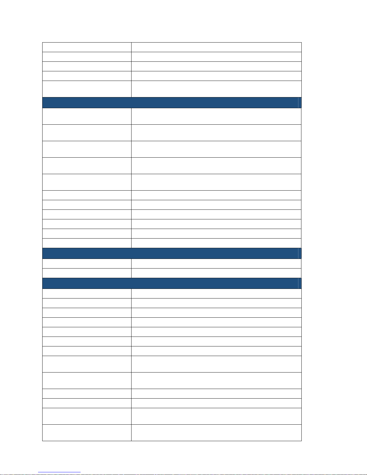
IP Dual Port PBXgateway and Remote System Administrator’s Guide
extStatBadPassword Amount of Disconnects from wrong Password being entered.
extStatBlockedCalls Number of Blocked Calls (no bandwidth).
extStatLostSignalStat Total Disconnects from Lost Signal
extStatLostSigDisconnect Number of Disconnections due to Lost Signal.
extStatLostSigReconnect
Number of Reconnections due to Lost Signals (only applies
to Call Suspend).
Group Name: extPortStatTable
extPstatPercentVC
Percentage value of all call types that User/Port was on a
“VC” (Voice Call).
extPstatPercentUP
Percentage value of all call types that User/Port was “UP”
(connected).
extPstatPercentRD
Percentage value of all call types that User/Port was “RD”
(ReaDy).
extPstatPercentNC
Percentage value of all call types that User/Port was “NC”
(Not Connected).
extPstatPercentXX
Percentage value of all call types that User/Port was “XX”
(disabled).
extPstatVCcount Number of “Voice Calls” in minutes.
extPstatVCaverage The average number of “Voice Calls”.
extPstatUPcount The number of minutes the User/Port has been “UP”.
extPstatUPaverage The average number of minutes the Port has been “UP”.
extPstatRDcount The number of minutes the User/Port has been “RD”.
extPstatRDaverage The average number of minutes the Port has been “RD”.
69
Group Name: extDiagnosticsTable
extDiagTest Names of Diagnostics tests.
extDiagResult Results of Diagnostics tests.
Group Name: extPortTable
extPtabPortID The Port ID names.
extPtabEnabled The “Enabled” value in the Ports Default & 1-2 menus.
extPtabAutoConnect The “Auto connect” value in the Ports Default & 1-2 menus.
extPtabBanner The “Banner” value in the Ports Default & 1-2 menus.
extPtabDescription The “Description” value in the Ports 1-2 menus.
extPtabUserID The “User ID” value in the Ports 1-2 menus.
extPtabLogout The “Logout” value in the Ports 1-2 menus (Remote only).
extPtabVoiceMethod
The “Voice” value in the Ports Default & 1-2 menus (Gateway
only).
extPtabVoicePath
The “Path” value in the Ports Default & 1-2 menus (Gateway
only).
extPtabVoiceCompanding The “Companding” value in the Ports Default & 1-2 menus.
extPtabVoiceDTMF The “DTMF” value in the Ports Default & 1-2 menus.
extPtabVoiceSilenceDetection
The “Silence Detection” value in the Ports Default & 1-2
menus (Gateway only).
extPtabVoicePacketTrace
The “Packet Trace” value in the Ports Default & 1-2 menus
(Gateway only).
Document Number: M-4100-MUC Version: Rev AA © Copyright 2007 Citel plc All Rights Reserved
Page 70
IP Dual Port PBXgateway and Remote System Administrator’s Guide
70
extPtabVoiceJitterDelay
The “Jitter Delay” value in the Ports Default & 1-2 menus
(Gateway only).
extPtabVoicePacketSize
The “Packet Size” value in the Ports Default & 1-2 menus
(Gateway only).
Group Name: extAlarmNotificationGroup
extAlarm Log messages that appear in the Log file.
Group Name: extSnmpControlGroup
extSnmpEnabled Indicates SNMP is enabled.
extTrapPriority Indicates the Priority setting for SNMP traps to be sent.
extTrapHost1 The IP address or HOST name to send 1st trap message.
extTrapHost2 The IP address or HOST name to send 2nd trap message.
extTrapHost3 The IP address or HOST name to send 3rd trap message.
extTrapHost4 The IP address or HOST name to send 4th trap message.
extTrapHost5 The IP address or HOST name to send 5th trap message.
extTrapHost6 The IP address or HOST name to send 6th trap message.
extTrapHost7 The IP address or HOST name to send 7th trap message.
extTrapHost8 The IP address or HOST name to send 12th trap message.
extTrapPath Path where traps are sent: WAN, LAN, BOTH
Group Name: extTopologyGroup
extTopType The device type of the main unit: Switch, Remote
extTopDevice1 Device type connected to Port 1.
extTopDevice2 Device type connected to Port 2.
Group Name: extSuspendTable
extSuspendEnabled Indicates if Call Suspend is Enabled.
extSuspendIpDestination
The IP address or HOST name to connect to, from Call
Suspend.
extSuspendTimeout Call Suspend timeout value.
extSuspendMode Call Suspend mode used: Ring, Lamp
extSuspendACDTone
Indicates if ACD Tone is enabled for individual Port (Remote
only).
Group Name: extRvpOverIpGroup
extRvpOverIpInterface The IP destination address.
Table 6: MIB Group Tables
Document Number: M-4100-MUC Version: Rev AA © Copyright 2007 Citel plc All Rights Reserved
Page 71

IP Dual Port PBXgateway and Remote System Administrator’s Guide
SNMP Setup
This section covers information for installing all support software, accessing and
identifying specific trap information, viewing the “Alarm Log” and walking through the MIB.
Set Up Steps
1. Load a third party-network management software package, such as HP OpenView®,
onto the PC used to manage the PBXgateway and Remote units.
2. Install the units’ configuration files, onto the same PC.
3. Add the units’ MIB to the third party-network management software package
database. This will allow the software to access the status and configuration
variables of the PBXgateway and Remote.
4. Set the password (Community String) to allow access to the units.
5. Format the Trap error messages from the PBXgateway and Remote into an easily
read form.
6. Enable SNMP within the MI.
71
Installing the MIB Files
The MIB files are necessary for the third party software to read the PBXgateway and
Remote status tables, and to receive readable SNMP Trap error messages.
Work with the following files:
mibs\Remotexxxx.mib (where xxxx refers to the Remote release).
Copy to: c:\ov\mibs
This file is the MIB for control of the Remote, in this case. This file must be compiled into
the third party software package.
Setting the Community Password
The units come with a default SNMP read password also known as a Community String.
This password must be specified inside the third party software to allow the user to view
MIB objects.
Before setting the password, the units must have an IP Address assigned by the network
administrator and must be part of the software “Network View”.
1. Access the “Network View” menu from within the third party software. Click on the
Icon of the device to be configured. Each Icon should be titled with the IP Address for
the device.
2. Type in the password next to Community. Click
password is: “public.” The Set Community password is not and may be ignored.
Document Number: M-4100-MUC Version: Rev AA © Copyright 2007 Citel plc All Rights Reserved
OK. The default read (community)
Page 72
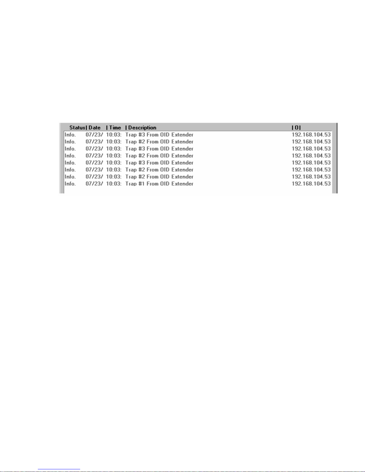
IP Dual Port PBXgateway and Remote System Administrator’s Guide
Configuring the Trap Host
The PBXgateway and Remote send alarm messages (SNMP Traps) to any Trap Host
with an associated IP Address that has been entered into the User Interface SNMP
Configuration Menu. These slots are named Trap Host 1, Trap Host 2, etc.
Trap Customization
The third party software will receive and display Trap messages from the units. But
without some configuration these messages will be simply a list of numbers, as shown:
72
Figure 36: Non-Customized Trap Messages
To display friendly and readable Trap messages, the software can be configured to
display all the information contained in the Trap Error messages sent by the PBXgateway
or Remote. Trap messages correlate with “log messages” within the MI.
Defining a Fatal Trap
Here is an example of setting up “HP Openview for Windows” to receive the Log
messages from the PBXgateway and Remote.
1. From within the third party software, navigate to the Add Trap window.
2. In the box Number: type: “1”
3. In box Name: type “Gateway (or Remote) Fatal Error”
4. In box Severity: select choice “Critical”
5. In box Description: type “$E, $1”
6. Delete any existing text.
7. Click on the OK button.
Defining an Error Trap
1. From within the third party software, navigate to the Add Trap window.
2. In the box Number: type: “2”
3. In box Name: type “Gateway (or Remote) Error”
4. In box Severity: select choice “Major”
5. In box Description: type “$E, $1”
6. Click on the OK button.
Document Number: M-4100-MUC Version: Rev AA © Copyright 2007 Citel plc All Rights Reserved
Page 73

IP Dual Port PBXgateway and Remote System Administrator’s Guide
Defining a Warning Trap
1. From within the third party software, navigate to the Add Trap window.
2. In the box Number: type: “3”
3. In box Name: type “Gateway (or Remote) Warning”
4. In box Severity: select choice “Warning”
5. In box Description: type “$E, $1”
6. Click on the OK button.
Defining an Info Trap
1. From within the third party software, navigate to the Add Trap window.
2. In the box Number: type: “4”
3. In box Name: type “Gateway (or Remote) Info”
4. In box Severity: select choice “Informational”
5. In box Description: type “$E, $1”
6. Click on the OK button.
73
Viewing the Customized Alarm Log
1. Click the Alarm icon.
Figure 37: Customized trap messages
2. The Customized trap messages are color coded for identification purposes:
a) “Red” – Trap messages that are considered Major/Critical
b) “Yellow” – Trap messages that are considered a “Warning”
c) “Purple” – Trap messages that are considered simply “Information”
Document Number: M-4100-MUC Version: Rev AA © Copyright 2007 Citel plc All Rights Reserved
Page 74

IP Dual Port PBXgateway and Remote System Administrator’s Guide
Using SNMP to monitor and Troubleshoot Problems
Here is an example of how to use SNMP management to monitor the PBXgateway and
Remote.
Example:
You have an PBXgateway with an IP address of “10.2.1.50”. The Remote has an IP
address of “10.5.3.50”. You want to monitor if there are lost signal conditions.
Use your SNMP manager to browse the “Remote.mib” and create a TRAP condition on
the object name “extStatLostSignalStat”. Get the current threshold value, for example “0”.
Trigger the TRAP when the threshold exceeds “0”.
If there is a Lost Signal condition, as shown in the MI menu under “Status->Connect>Connect Stats”, or anything higher than zero, a message will be indicated on the SNMP
manager.
74
Document Number: M-4100-MUC Version: Rev AA © Copyright 2007 Citel plc All Rights Reserved
Page 75
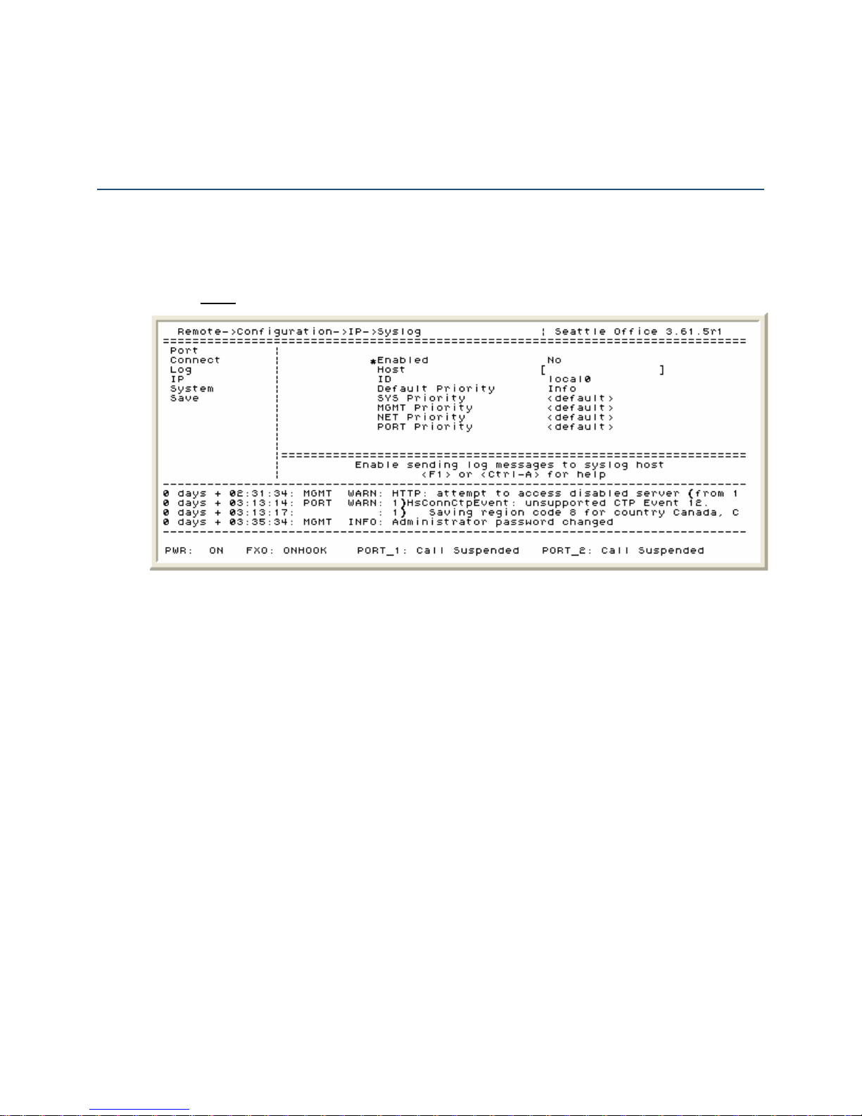
IP Dual Port PBXgateway and Remote System Administrator’s Guide
9 USING SYSLOG
Configuring Syslog
The Syslog feature allows for the writing of the log file information to a centralized logging
server if required. System trouble shooting is performed by configuring the log to report
specific events in a prioritized manner. The Syslog configuration screen is shown below:
Path: Gateway (Remote) ->Configuration->IP->Syslog
75
Figure 38: Configuring Syslog
1. Enabled Yes/No – Enabling allows for the log data to be written to the Syslog host
and disabling turns this feature off.
2. Host – This is the IP address that the log file information is to be written to.
3. ID – The ID is used to identify the specific unit that the log is being generated from.
The range is from “local0” to “local7.”
4. Default Priority - Allows for the selection of what log types will be displayed first in
the log file for the “<default>” setting.
5. SYS Priority – Can be left at the default of “Info” or be changed to Fatal, Error,
Warning, Info, Debug or Trace.
6. MGMT Priority – Can be left at the default of “Info” or be changed to Fatal, Error,
Warning, Info, Debug or Trace.
7. Net Priority – Can be left at the default of “Info” or be changed to Fatal, Error,
Warning, Info, Debug or Trace.
8. Port Priority – Can be left at the default of “Info” or be changed to Fatal, Error,
Warning, Info, Debug or Trace.
Document Number: M-4100-MUC Version: Rev AA © Copyright 2007 Citel plc All Rights Reserved
Page 76

IP Dual Port PBXgateway and Remote System Administrator’s Guide
The log priority definitions:
Log Priority Definition
Fatal Unit is not functioning
Error Failure
Warning Problem with unit but still operational
Info Remote session connected
Debug Detailed message
Trace Packet type tracing
Table 7: Log Priority Definitions
Third Party Application for Syslog
A third party application is required for receiving the log file information. An application
such as Kiwi Syslog Daemon is a freeware Syslog Daemon for Windows. It receives, logs,
displays and forwards Syslog messages from hosts such as Citel’s EXTender products,
routers, switches, Unix hosts and any other syslog enabled device. However, any third
party Syslog application can be used.
76
For the Kiwi Syslog Daemon it is a simple matter of opening the application. The log files
will be received immediately (assuming a valid Host IP address has been input). An
example of the Kiwi Syslog Daemon application is shown below:
Figure 39: Kiwi Syslog Daemon
Document Number: M-4100-MUC Version: Rev AA © Copyright 2007 Citel plc All Rights Reserved
Page 77

IP Dual Port PBXgateway and Remote System Administrator’s Guide
10 TROUBLESHOOTING
This chapter provides information to locate, isolate, and correct functional problems with
the PBXgateway and Remote should the need arise.
This chapter is divided into six principal areas for troubleshooting:
Baseline Checklist – A list of simple checks used as a starting point for
troubleshooting the devices. It covers basic installation requirements, wiring info and
network information.
Status LEDs – Single and tri-color LEDs, located on the front and back panels of
each unit. The LEDs blink in specific sequences indicating the unit status during
Power-Up as well as providing status information on the System and Ethernet (LAN)
connections during normal operations
Troubleshooting Procedures – A set of procedures providing step-by-step
instructions to identify and rectify problems.
Voice Quality Expectations – Information on common issues associated with voice
compression.
77
Status Menus – Diagnostic menus providing statistical information on all telephone
ports, Connect stats, Log and IP stats and general System information.
Remote Phone System Messages – A chart listing error messages that are
displayed on the Remote phones.
Baseline Checklist
The Baseline Checklist is a logical list of items that are associated with an active and
operational installation. These items should be checked BEFORE you attempt to
troubleshoot either the PBXgateway or the Remote.
If you find any of the items are not as stated, you must correct them and then check the
remaining items for both units to verify a complete installation.
Network Checklist
Verify that the existing network is capable of transmitting and receiving data packets.
Verify the correct cable is used to connect the unit to the network device.
Check that the IP address information (IP Address, Subnet Mask, Default Router) for
the PBXgateway and Remote are valid and set correctly.
PBXgateway Checklist
Verify that the unit is plugged into an active AC outlet.
Verify that the cables between the unit and the PBX or KTS are secure.
Verify that the Ethernet cable is connected and there is an active link status on the
Gateway and Network Hub/Switch.
Verify the PBX port is working correctly when a digital telephone is connected directly
to it.
Verify that the correct PBX type selected.
Document Number: M-4100-MUC Version: Rev AA © Copyright 2007 Citel plc All Rights Reserved
Page 78
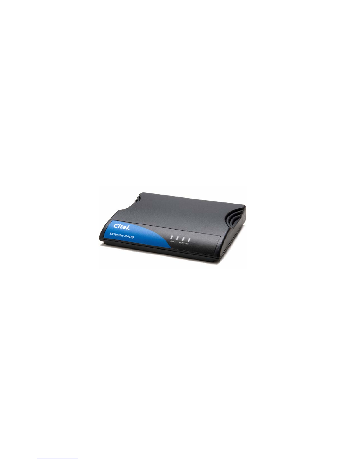
IP Dual Port PBXgateway and Remote System Administrator’s Guide
Remote Checklist
Verify that the power supply is plugged into an active AC outlet and the power cable is
plugged into the unit.
Verify that the Ethernet cable is connected and there is an active link status on the
Remote and Network Hub/Switch.
Verify the digital telephone works correctly if connected directly to the PBX port.
Verify that the correct PBX is selected.
Status LEDs
When the units are powered-up, a series of self-diagnostic tests are performed and
displayed as a series of LED blinks. The following sections list the different status
sequences.
Power Up Sequence
The “Status” LED on the front of the unit will blink for several seconds as the module is
initializing. See next page for the complete list of LED sequences.
78
Figure 40: Front Panel
Document Number: M-4100-MUC Version: Rev AA © Copyright 2007 Citel plc All Rights Reserved
Page 79

IP Dual Port PBXgateway and Remote System Administrator’s Guide
Power up LED Sequence
During power up of the PBXgateway and Remote the following LED flashing sequences
are presented:
Test LED Status
DRAM Test Status LED 1 – Green Flicker
Status LED 2 – Off
Analog Port LED – Off
Self Test Status LED 1 – Solid Green
Status LED 2 – Off
Analog Port LED – Off
ROM Countdown Status LED 1 – Solid Green
Status LED 2 – Off
Analog Port LED – Green Flicker
Loading Image Status LED 1 – Green Flashing
Status LED 2 – Off
Analog Port LED – Solid Green
Loading Image Successful Status LED 1 – Solid Green
Status LED 2 – Off
Analog Port LED – Solid Green
Table 8: Power up LED Sequence
79
Document Number: M-4100-MUC Version: Rev AA © Copyright 2007 Citel plc All Rights Reserved
Page 80
IP Dual Port PBXgateway and Remote System Administrator’s Guide
Trouble Shooting Procedures
The following procedure provides a step-by-step process for identifying and rectifying
installation problems with the PBXgateway and Remote. Each step is a question requiring
a “Yes” or “No” response. Each response has a series of checks or actions necessary to
correct the problem.
Prerequisites:
Both units must be powered-up with some LED blinking patterns visible.
Both units must be connected to an active network capable of sending and receiving
packets.
System Status LEDs
After the units have completed the self-diagnostic tests, is the Status 1 LED on (solid
green) on each unit? If the Status 1 LED is not lit, check that the power cable is properly
connected. Below is the complete list of the System Status LEDs:
System Status LED Status
Power off Status LED 1 – Off
Status LED 2 – Off
Hardware problem detected
during memory test
Hardware problem detected
during Self Test
Memory Tests Status LED 1 – Green Flicker
Loading Firmware Status LED 1 – Solid Green after Flicker
System firmware load Failed Status LED 1 – Green Flashing
Table 9: System Status LEDs
Status LED 1 – Off
Status LED 2 – Solid Green
Status LED 1 – Off
Status LED 2 – Solid Green
Status LED 2 – Off
Status LED 2 – Off
Status LED 2 – Green Flashing
80
Port Status LED
After the units have gone through the self-diagnostics tests and loading the runtime
image, the telephone port LED should be solid green. This indicates that the telephone
port is connected to a digital port on the PBX and to a telephone connected to the
Remote, but not extended.
1. If the Port LED is OFF this indicates the port is disabled. The telephone port is
enabled by default. To confirm the telephone port status go to Gateway (Remote) >Configuration->Port and check that the
2. If the port LED blinks with a green flicker this indicates that the port is enabled but
there is a bad connection to the PBX or phones.
3. If the ports are ready, press ‘1’ to connect to the PBXgateway. (If Auto-connect is
enabled, it is not necessary to press ‘1’.) As the telephone is connected the LED will
begin to flash slowly. This means that the telephone is enabled but still not in use (onhook).
4. Check the log messages within the MC for obvious port errors.
5. Are there any messages displayed on the telephones connected to the Remote?
Document Number: M-4100-MUC Version: Rev AA © Copyright 2007 Citel plc All Rights Reserved
Enabled field is set to “Yes.”
Page 81

IP Dual Port PBXgateway and Remote System Administrator’s Guide
6. Place a call using a telephone connected to the Remote. As the remote user places a
call the LED will begin to flash faster. This means that the telephone is extended and
in use (off-hook) by the remote user.
7. Check the wiring to the PBX.
8. Is the Voice Quality acceptable?
Resetting the Port
Try resetting the port on the PBXgateway and Remote:
1. To reset the telephone ports:
a)
Path: Gateway (and Remote) ->Utilities->Diagnostics->Reset Port
b) Enter the port number or ‘all’ to reset all the ports
Below is the complete list of Port Status LEDs:
Port Status LED Status
Port is Disabled Status LED 1 – Off
Status LED 2 – Off
Port Enabled – Valid phone
(Remote) or PBX port detected
(PBXgateway)
Port Enabled – Valid phone
(Remote) or PBX port not
detected (PBXgateway)
Phone EXTended and onhook Status LED 1 – Green with ‘off’ Blink
Phone EXTended and offhook Status LED 1 – Green Flashing
Phone using Analog port Status LED 1 – Off with Green Blink
Phone EXTended and port in
Call Suspend mode
Table 10: Port Status LEDs
Status LED 1 – Solid Green
Status LED 2 – Solid Green
Status LED 1 – Green Flicker
Status LED 2 – Green Flicker
Status LED 2 – Green with ‘off’ Blink
Status LED 2 – Green Flashing
Status LED 2 – Off with Green Blink
Status LED 1 – Slow Green Flashing
Status LED 2 – Slow Green Flashing
81
Analog Port Status LEDs
After the units have gone through the self-diagnostics tests and loading the runtime
image, the Analog port LED should be off. This indicates that the Analog port is disabled
(default value). The following is a complete list of the Analog Port status LEDs:
Analog Port Status LED Status
Analog Port is Disabled Analog Port LED – Off
Analog Port is Enabled Analog Port LED – Solid Green
Analog Port off hook or
incoming call detected
Boot count-down timer Analog Port LED – Green Flicker
Table 11: Analog Port Status LED
Document Number: M-4100-MUC Version: Rev AA © Copyright 2007 Citel plc All Rights Reserved
Analog Port LED – Green with off Blink
Page 82

IP Dual Port PBXgateway and Remote System Administrator’s Guide
Test the IP Connection
If all of your Status LEDs indicate the units are installed properly, but you still cannot
connect the remote telephone, you should test the IP connection. This test will not run if
the telephone is off-hook (in an active call).
1. Access the MC.
2. Access the diagnostics menu via Gateway (Remote) ->Utilities->Diagnostics->Test IP
3. Using the default values, select “Begin test.” This test will send voice packets to the
offsite unit and will count the packets as they are sent back.
4. The MC will run the test and, upon its completion, a test results window appears as
shown below.
Figure 41: Test Results Window
82
5. From a PC on the remote network make sure that you can reliably ping the
PBXgateway.
6. From a PC on the corporate network, make sure you can reliably ping the Remote on
the remote network.
Voice Quality Expectations
The Remote uses an industry-standard voice compression method to allow multiple users
to connect using less bandwidth. While the voice quality should remain excellent in all
circumstances, you may notice some minor issues depending on the voice compression
selected. The person you are talking to on the other end should not notice these affects in
most instances.
The G.729A algorithm only uses 8Kbps for its audio path (plus overhead). It therefore
dramatically reduces the amount of network bandwidth required to extend multiple
telephones. It also provides excellent voice quality to all parties involved in a
conversation. However, this algorithm is designed to optimize audio in the frequency
range of the human voice. Tones outside of that range may sound muffled. Also, listening
to audio that has already been compressed may sound slightly less clear. Here are some
of the affects you may notice with over compressed audio:
1. ‘Hold’ music may sound less clear.
2. Dial tone, DTMF tones, and telephone rings may sound slightly garbled, particularly
on the speakerphone. They still should function properly 100% of the time.
3. May experience some minor echo and reduced audio clarity when calling some cell
phones. They often already compress audio.
4. May hear some echo and notice minor delay in the conversation if calling
internationally. This is caused by the delay in providing compressed audio and the
fact that calling internationally may already introduce some delay.
If you are experiencing any of these problems and feel that it is not presenting you with
adequate voice quality, we recommend using the ADPCM32 or G.711 voice compression
method. While it requires more network bandwidth, it uses less voice compression and
therefore minimizes the chances that any of these effects ever occur.
Document Number: M-4100-MUC Version: Rev AA © Copyright 2007 Citel plc All Rights Reserved
Page 83

IP Dual Port PBXgateway and Remote System Administrator’s Guide
It is important to know the following:
5. The type of audio problem; for example: echo, broken or choppy audio, lost calls, etc.
6. When does the problem occur?
a) All calls?
b) Internal calls only?
c) External calls only
d) Intermittently some external calls?
7. Do all users experience the problem?
Echo Problems
Understanding and Correcting Echo Problems
The PBXgateway and Remote employ the industry standard G.165 echo canceller with
some proprietary improvements to help eliminate or reduce echo even further. However, it
is not possible to cancel all instances of echo 100% of the time. It should be noted that
echo perceived by extended PBX users will not be perceived by the party on the other
end of the call.
Remote Impact on Echo
83
Because the Remotes deal exclusively with digital audio on the line side of a PBX, they
cannot cause any echo. However, if you experience any echo from your connection to the
PSTN (Public Switched Telephony Network), the Remote application could make it
noticeable because of increased delay in the audio path. For example, if echo occurs on a
line after only a few milliseconds, your ear cannot detect the echo. However, if the echo
occurs after 100, 50, or even 20 milliseconds, your ear will likely detect the problem. The
G.165 echo canceller can cancel echo only up to certain limitations.
If you experience echo on all external calls, you probably have a problem with your PSTN
trunk lines. Most likely they are analog, and those analog lines are generating a great deal
of echo when interfacing with your PBX. Non-extended PBX telephones may not perceive
the echo, due to the fact that echo without delay does not sound like echo.
If you have a noticeable echo problem, you should look into the following:
Cause:
The most common causes of consistent echo on all external calls are analog trunk
lines that are out of specification, or a problem with the termination within the PBX.
Most commonly there is an impedance mismatch between the analog line and your
PBX. Also, the db level of the analog circuit may be too high. Analog circuits that are
“hot” are a common cause of echo. Again, that echo may not be perceived on non extended telephones, but that is only because there is no delay.
Possible solution:
If you have analog lines, you should consult your local telephone company and ask
for the exact specifications of that line. They may need to go onsite to measure the
characteristics of your analog circuits. If you only experience echo occasionally on
external calls, your system is probably fine. The echo probably only occurs when
calling to or receiving calls from a party that is using:
à analog lines
à a cell telephone
à analog trunks on their telephone system. In this case there is little you can do.
The echo canceller included with the Remotes will usually cancel this echo after a
second or two, but occasionally the echo goes beyond its capabilities. However, it
should be noted that the party on the other end of the call will not experience this
Document Number: M-4100-MUC Version: Rev AA © Copyright 2007 Citel plc All Rights Reserved
Page 84

IP Dual Port PBXgateway and Remote System Administrator’s Guide
echo. If you experience a slight echo on all external calls, but it goes away after a
second or two, that is normal with analog trunk lines. If you have analog trunks on
your PBX, the echo canceller frequently takes a second or two to detect levels of
what is echo and what is voice, and then it starts to cancel the echo. The only
way to eliminate that situation is to replace your analog trunks with digital trunk
lines.
84
Document Number: M-4100-MUC Version: Rev AA © Copyright 2007 Citel plc All Rights Reserved
Page 85
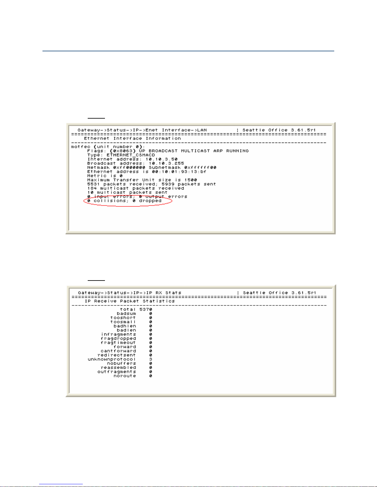
IP Dual Port PBXgateway and Remote System Administrator’s Guide
Status Menus
The following are examples of the various status information screens available to assist
with trouble shooting should any issues with voice quality or system performance arise.
Ethernet Interface
A large number of collisions shown here could indicate network traffic problems.
Path: Gateway (Remote) ->Status->IP->Enet Interface->LAN
85
Figure 42: Ethernet Interface Status Screen
IP Received Packet Statistics
Look for any value that increases other than “total” and “cantforward.”
Path: Gateway (Remote) ->Status->IP->IP RX Stats
Figure 43: Received Packets Status Screen
Document Number: M-4100-MUC Version: Rev AA © Copyright 2007 Citel plc All Rights Reserved
Page 86

IP Dual Port PBXgateway and Remote System Administrator’s Guide
Active IP Connections
A large number of collisions reported could indicate network traffic problems.
Path: Gateway (Remote) ->Status->IP->IP Active
Figure 44: IP Active Status Screen
86
ARP Table
Make sure the default gateway can be seen from this status screen.
Path: Gateway (Remote) ->Status->IP->IP ARP
Figure 45: IP ARP Status Screen
Document Number: M-4100-MUC Version: Rev AA © Copyright 2007 Citel plc All Rights Reserved
Page 87

IP Dual Port PBXgateway and Remote System Administrator’s Guide
IP Route Table
Make sure the default gateway can be seen from this status screen.
Path: Gateway (Remote) ->Status->IP->IP Routes
Figure 46: IP Routes Status Screen
87
General Information Screen
This will list all the pertinent system information. The information shown here is used to
verify software release, IP information, and system parameters.
Path: Gateway (Remote) ->Status->System->General Info
Figure 47: General Info Status Screen
Document Number: M-4100-MUC Version: Rev AA © Copyright 2007 Citel plc All Rights Reserved
Page 88

IP Dual Port PBXgateway and Remote System Administrator’s Guide
Remote Phone System Messages
Error messages will appear on the telephone set at the remote site when a connection
attempt fails. The telephone will usually show “Connect Error” followed by one of the
following prompts (not all messages are preceded by “Connect Error”):
Message Description Action
Already Connected Remote port is already connected Reset port on PBXgateway
Assigned port Busy
Assigned port Down
Carrier Lost
Connect rejected
Connect Timeout
Network Disabled
Network Down
Network in Use
Network not ready
No bandwidth
Table 12: Remote Phone System Messages
The PBXgateway port is in use
by another user
The PBXgateway port is not
available due to problems with
the port (port LED shows green
flicker)
Displayed if the network
connection to the PBX or KTS is
lost
The PBX or KTS rejects the
connection attempt
Remote cannot connect to the
PBXgateway
The network device is not
connected, is being used, or is
not active
The network device has a
problem
The network device is being used
by another device
The network device is not ready
for use
The bandwidth is over
subscribed. No network
bandwidth is available for
telephone signaling
88
Wait until port becomes available
or reset the port on the
PBXgateway and try to reconnect
Check physical connection at the
PBXgateway
Check network links
Attempt to reconnect when
network running properly
Verify connect password
Check network links
Attempt to reconnect
Check the network connection on
the PBXgateway
Check network link and device
Check network link and device
Reset the ports and attempt to
reconnect
Ensure network devices are
working properly
Change voice compression
Document Number: M-4100-MUC Version: Rev AA © Copyright 2007 Citel plc All Rights Reserved
Page 89

IP Dual Port PBXgateway and Remote System Administrator’s Guide
11 CONNECTING TO OTHER CITEL
PRODUCTS
The PBXgateway and Remote can also connect with other Citel Technologies EXTender
products. Other PBXgateways and EXTenders offered by Citel are based on the same
configuration Management Interface as described in this document. The other products
discussed are multi-port versions (8 to 24 ports) that offer at least the same features and
functionality as the PBXgateway and Remote described in this document. For details on
the full EXTender product line refer to
When the installation requires multiple EXTenders (Remotes) to connect to a single
PBXgateway the following MUST be configured properly for a successful connection:
1. User IDs on the Gateway and Remote must be configured
à
Path: Gateway (and Remote) ->Configuration->Port
2. Port Matching on the Gateway should be disabled.
www.citel.com or contact Sales at 1-888-454-5828.
89
à
Path: Gateway (and Remote) ->Configuration->Connect
Software Compatibility
PBX Type
Definity
8/12 port BOCR V3.43r2 Remote V3.61.8r1 IP
24 port V2.16r4 Remote V3.61.8r1 IP
24 port GWII V3.43r2 Remote V3.61.8r1 IP
PBXgateway V3.61.8r1 IP 4000 V2.16r4 IP
Magix
8/12 port BOCR V3.43r2 Remote V3.61.8r1 IP
24 port V2.16r4 Remote V3.61.8r1 IP
24 port GWII V3.43r2 Remote V3.61.8r1 IP
PBXgateway V3.61.8r1 IP 4000 V2.16r4 IP
IP Office
8/12 port BOCR V3.43r2 Remote V3.61.8r1 IP
24 port V2.16r4 Remote V3.61.8r1 IP
24 port GWII V3.43r2 Remote V3.61.8r1 IP
PBXgateway V3.61.8r1 IP 4000 V2.16r4 IP
PBX Type
Ericsson
PBXgateway
Type
8/12 port V2.16r4 Remote V3.61.8r1 IP
8/12 port V2.16r4 Remote V3.61.8r1 IP
8/12 port V2.16r4 Remote V3.61.8r1 IP
PBXgateway
Type
8/12 port V2.16r4 Remote V3.61.8r1 IP
Software
Version
Software
Version
EXTender Type
EXTender Type
Software
Version
Software
Version
Connect
Type
Connect
Type
Document Number: M-4100-MUC Version: Rev AA © Copyright 2007 Citel plc All Rights Reserved
Page 90
IP Dual Port PBXgateway and Remote System Administrator’s Guide
8/12 port BOCR V3.43r2 Remote V3.61.8r1 IP
24 port V2.16r4 Remote V3.61.8r1 IP
24 port GWII V3.43r2 Remote V3.61.8r1 IP
PBXgateway V3.61.8r1 IP 4000 V2.16r4 IP
PBX Type
Meridian
PBXgateway
Type
8/12 port V2.16r4 Remote V3.61.8r1 IP
Software
Version
EXTender Type
Software
Version
Connect
Type
8/12 port BOCR V3.43r2 Remote V3.61.8r1 IP
24 port V2.16r4 Remote V3.61.8r1 IP
24 port GWII V3.43r2 Remote V3.61.8r1 IP
PBXgateway V3.61.8r1 IP 4000 V2.16r4 IP
PBX Type
Norstar
PBXgateway
Type
8/12 port V2.16r4 Remote V3.61.8r1 IP
Software
Version
EXTender Type
Software
Version
Connect
Type
8/12 port BOCR V3.43r2 Remote V3.61.8r1 IP
24 port V2.16r4 Remote V3.61.8r1 IP
24 port GWII V3.43r2 Remote V3.61.8r1 IP
PBXgateway V3.61.8r1 IP 4000 V2.16r4 IP
Table 13: Software Compatibility Table
90
Document Number: M-4100-MUC Version: Rev AA © Copyright 2007 Citel plc All Rights Reserved
Page 91

IP Dual Port PBXgateway and Remote System Administrator’s Guide
12 FILE MANAGEMENT AND SYSTEM
UPGRADES
Flash Files
The PBXgateway and Remote contain a flash file system to store basic configuration files,
the actual firmware and the instructions necessary for starting the units. The flash memory
system retains stored data even with no external power applied.
Access to the flash file system is gained using a PC (FTP or Telnet access via LAN). FTP
must be enabled, if that is the method you are using, and an administrator’s password
should be configured, to control access.
Firmware images stored in the flash file system are saved with extension “.mab.” These
files use binary format.
Configuration files stored in the flash file system are saved with “.swt” extensions for the
PBXgateway and “.rem” extensions for Remote. All changes you make to the
configuration must be saved to the flash file to be applied. The MI prompts you to save
changes when necessary.
91
Call Back files stored in the flash file system are saved with the “.cbk” extension. They
contain specific information for the PBXgateway and Remote boot process (IP
addressing, active configuration file, firmware for boot). The PBXgateway saves “.cbk”
files to allow it to contact remote users that are currently disconnected. This file is also
used for Remote Login capabilities.
Configuration File Management
Changing the Active Configuration File
When the PBXgateway or Remote is powered-up, the flash file system loads a
configuration file – “.rem” (Remote) or “.swt” (PBXgateway) – which contains all
parameters necessary for operation. You may change this “.rem” or “.swt” file so that a
different set of parameters loads.
The default configuration file shipped with the units is “runtime.rem” or “runtime.swt.” To
change this go to Gateway (Remote) ->Utilities->Upgrade->Config File. Select an existing
“.rem” (Remote) or “.swt” (Gateway) file from the list displayed. The display reads
“Change Configuration file to …..” Enter [Y]es or [N]o. Assuming you type “[Y]es” to
change the configuration file, you are prompted to reboot.
This change will not take effect without a reboot. All changes made to the PBXgateway or
Remote parameters will be saved to the file you selected.
Document Number: M-4100-MUC Version: Rev AA © Copyright 2007 Citel plc All Rights Reserved
Page 92

IP Dual Port PBXgateway and Remote System Administrator’s Guide
Edit Non-active Configuration Files
The PBXgateway and Remote can be used in different applications requiring different
parameters. You may need to set up separate configuration files to accommodate custom
parameters for each application.
The ability to modify any non-active configuration file enables you to quickly set up new
units based on existing configuration parameters.
To edit the “active” configuration file, use the “Configuration” menu. Go to Gateway
(Remote) ->Utilities->File->Edit Config
Type “r” for a Remote file or “g” for a Gateway file.
Select a configuration file from those available files. Press Enter.
Modify the parameters as required.
Select “save” and press Enter to save changes.
A message is displayed asking you to confirm that you want to save your changes to
the file you selected earlier. Type “[Y]es” to save the changes to that file, “[N]o” to
discard your changes or “[S]pecify” to specify a different file name
92
Creating a New Configuration File
To create a new configuration file go to Gateway->Utilities->File->Edit Config.
Type “r” for a new Remote file or “g” for a new Gateway file.
Select <new file> from the list.
Type a name for the new file. Do not add an extension – that is added automatically.
Press Enter.
File names must be a maximum of 12 characters.
Modify parameters as required.
Select “save” and press Enter to save changes.
A message is displayed asking you to confirm that you want to save your changes to
the file you selected earlier. Type “[Y]es” to save the changes to that file, “[N]o” to
discard your changes or “[S]pecify” to specify a different file name
Document Number: M-4100-MUC Version: Rev AA © Copyright 2007 Citel plc All Rights Reserved
Page 93

IP Dual Port PBXgateway and Remote System Administrator’s Guide
Upgrading the Software
The upgrade process involves three phases. These should be executed in the following
order:
1. File Management. This phase includes:
a) Examining the flash file system
b) Saving an active image file as the default
c) Deleting outdated files
d) Querying the flash file system
e) Optimizing the flash file system
2. File Upload
3. File Upgrade
The PBXgateway and Remote units use image files with the “*.mab” extensions.
93
File Management
Examining the Flash File System
This procedure determines how many image files are on the flash file system.
Path: Gateway (Remote) ->Utilities->Upgrade->Image List
Figure 48: Image List
If “default.mab” is the only file displayed in the list, go to Optimizing the Flash File System
on the next page. Otherwise follow the steps to save the active image file as the default.
Document Number: M-4100-MUC Version: Rev AA © Copyright 2007 Citel plc All Rights Reserved
Page 94

IP Dual Port PBXgateway and Remote System Administrator’s Guide
Saving the Active Image File as the Default
Saving the active image file as the default:
1. Deletes the existing “default.mab” file on the unit
2. Renames the image that is currently live to default.mab
3. A copy of the current live image remains on the unit after the upgrade is complete
4. If the currently live image is “default.mab” the message “Currently running default
image” is displayed
This process requires the system to be rebooted and this will cause active phones to be
taken out of service for a few minutes.
Path: Gateway (Remote) ->Utilities->Upgrade->Default Image
Type “[Y]es” to make the changes specified and reboot.
Figure 49: Default Image
94
Querying Flash File System
Before loading your new image file into the Flash File System, ensure that there is enough
free memory space for it. If the free space is less than 3,000,000 bytes, you must delete
files which are not in used by the system (see
Path: Gateway->Utilities->Upgrade->Free Space
Figure 50: Free Space
Deleting Outdated Files on the next page).
Document Number: M-4100-MUC Version: Rev AA © Copyright 2007 Citel plc All Rights Reserved
Page 95
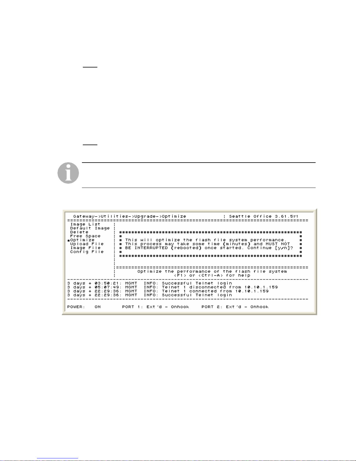
IP Dual Port PBXgateway and Remote System Administrator’s Guide
Deleting Outdated Files
You must delete all “.mab” files to ensure there is room for the new update file.
Path: Gateway->Utilities->Upgrade->Delete
All files not in use are listed – this does not include “default.mab” or the active image file.
If these are the only files, a message is displayed stating that all files are in use.
Select a file to delete and press Enter. Type “[Y]es” to confirm that you want to delete the
file.
Optimizing the Flash File System
Optimizing speeds up the subsequent file upload.
Path: Gateway (Remote) ->Utilities->Upgrade->Optimize
Do not optimize the flash file system when the unit is active. If the flash file is optimized
while the unit is being used it may cause the flash file to become corrupt and render the
units unusable.
95
Type “[Y]es” to optimize the flash file system.
Figure 51: Optimize
Document Number: M-4100-MUC Version: Rev AA © Copyright 2007 Citel plc All Rights Reserved
Page 96
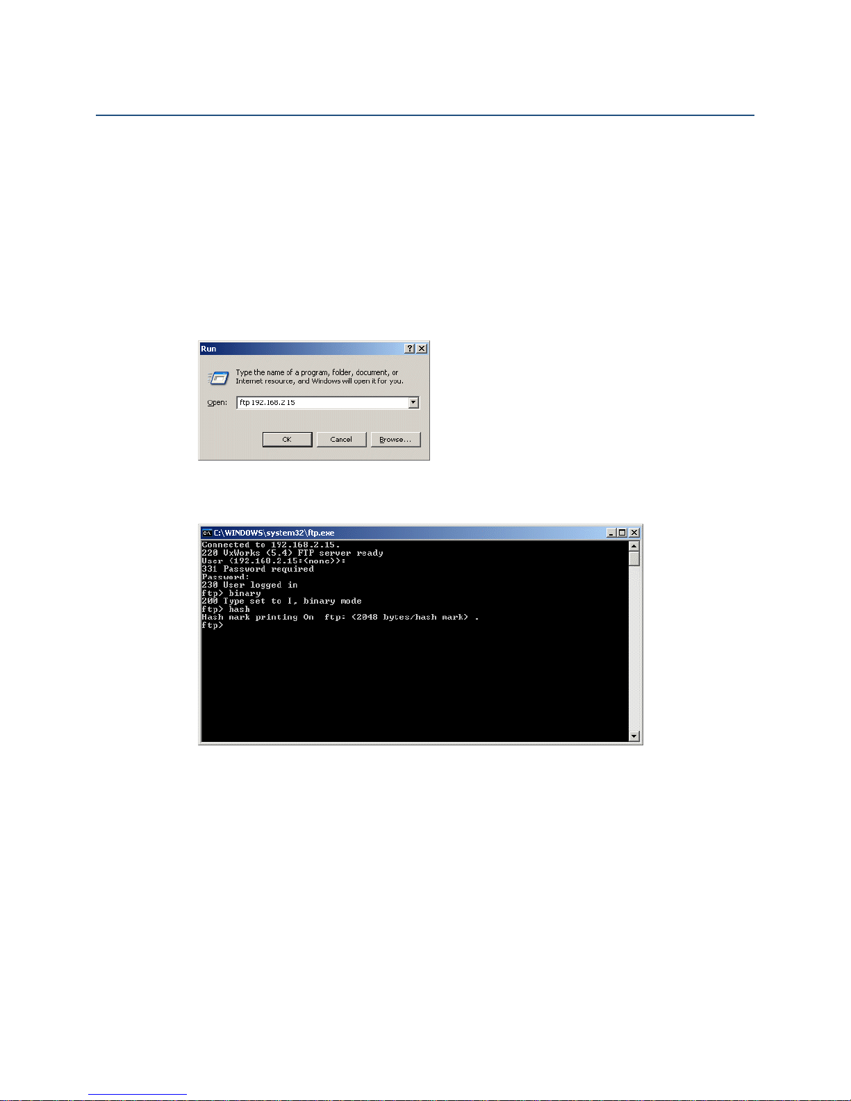
IP Dual Port PBXgateway and Remote System Administrator’s Guide
File Upload
Via FTP
Each unit must have Telnet and FTP enabled, and a valid IP address assigned before
proceeding. To set up Telnet and FTP see the PBXgateway’s
Telnet, Rlogin and FTP
Rlogin and FTP
section within this document.
To connect to the PBXgateway or Remote unit using FTP:
1. On a PC running Windows XP, for example, go to the “Start” menu and select the
“Run” application. Type “ftp” followed by the unit’s IP address and click OK.
section and the Remote’s Essential IP Parameters – Telnet,
96
Essential IP Parameters –
Figure 52: Windows “Run” Application
The following screen is presented:
Figure 53: FTP session
2. Press Enter at the “User” prompt
3. At the “Password” prompt press enter if there is no password. If a password has been
set enter the password followed by Enter.
4. At the “ftp” prompt type “bi” (binary) and press Enter
5. At the second “ftp” prompt type “hash” (for # marks to be displayed while loading the
file)
6. At the third “ftp” prompt type:
a) ftp <path to file>, where the “path to file” is the full path to access the file from the
administrator’s PC (i.e. c:\EXTender\Updates\3.61.5r2.mab)
b) As the file is being transferred progress is indicated by a stream of “#” symbols
presented across the screen. The entire file upload takes approximately 15
minutes.
Document Number: M-4100-MUC Version: Rev AA © Copyright 2007 Citel plc All Rights Reserved
Page 97
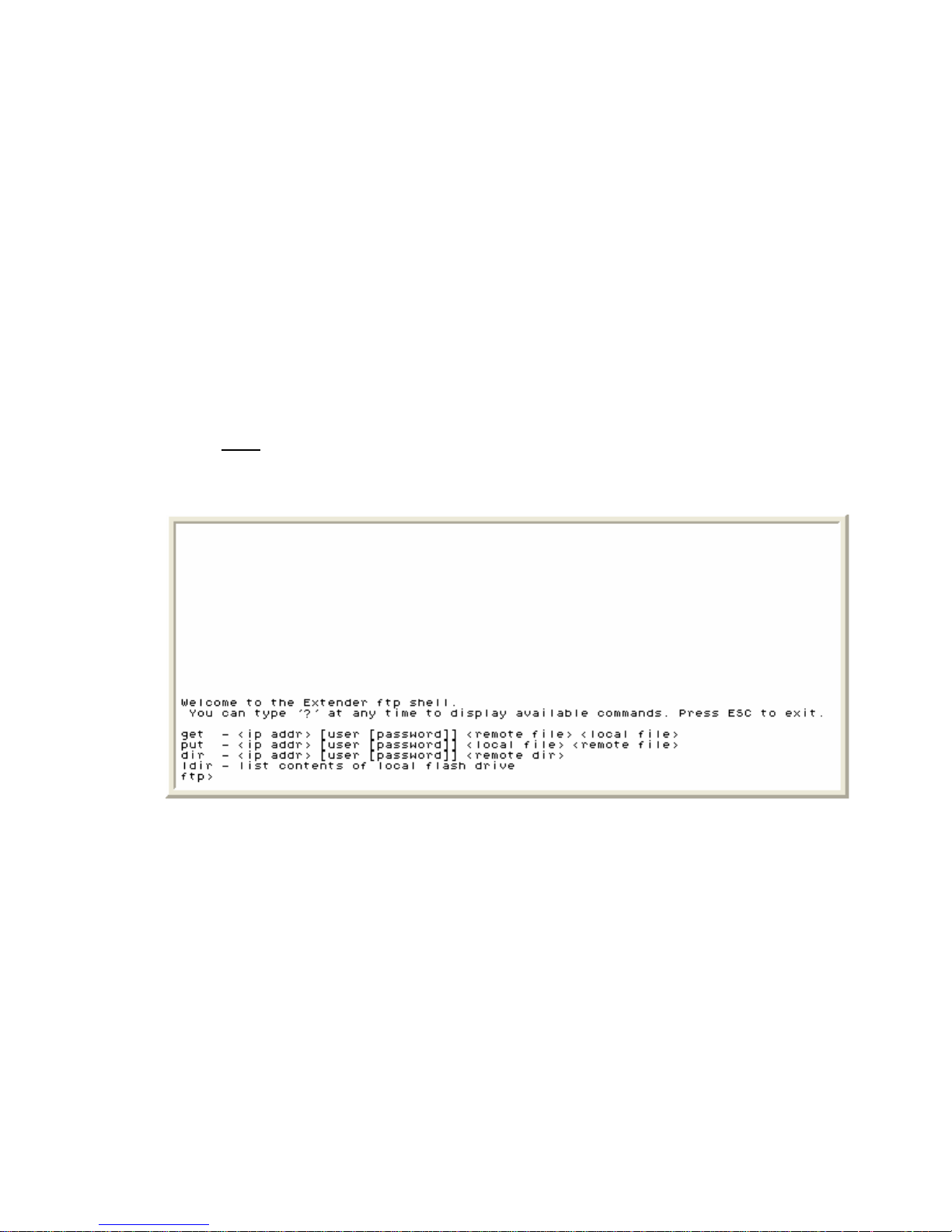
IP Dual Port PBXgateway and Remote System Administrator’s Guide
7. When the file transfer is complete the “ftp” prompt will be presented. Type “quit” and
press Enter. The image may now be copied to multiple units if required. See the “Via
In-Band Upload” section for details
97
8. The unit is now ready to upgrade to the new software image. See the
Via FTP Client
The PBXgateway or Remote unit can act as an FTP client to download the image file from
an FTP Server.
Each unit must have Telnet and FTP enabled and an accessible (pingable) IP address
assigned before proceeding.
To set up Telnet and FTP see the PBXgateway’s
Rlogin and FTP
FTP
Path: Gateway (Remote) ->Utilities->Upgrade->Upload File->FTP Client
1. The ftp shell appears:
File Upgrade
section for details.
Essential IP Parameters – Telnet,
section and the Remote’s Essential IP Parameters – Telnet, Rlogin and
section within this document.
2. At the “ftp” prompt enter:
a) Dir xxx.xxx.xxx.xxx yyy zzz <path>, where:
à xxx.xxx.xxx.xxx is the IP address of the ftp server
à yyy zzz is the login user and password for the ftp server
à <path> is the full path of the directory holding the image file
For example, dir 192.168.2.22 user1 pswd1 c:\EXTender\update
3. Press Enter to check that the image file with the “.mab” extension is available in that
directory of the ftp server.
Document Number: M-4100-MUC Version: Rev AA © Copyright 2007 Citel plc All Rights Reserved
Figure 54: FTP session
Page 98

IP Dual Port PBXgateway and Remote System Administrator’s Guide
4. Assuming that the file is present at the “ftp” prompt type:
a) get xxx.xxx.xxx.xxx yyy zzz <path> <new file>, where:
à xxx.xxx.xxx.xxx is the IP address of the ftp server
à yyy zzz is the login user and password for the ftp server
à <path> is the full path to the image file including the file name
à <new file> is the name that the file is to be given on the flash file system
For example, get 102.168.2.22 user1 pswd1 c:\EXTender\update\3.61.5r1.mab
3.61.5r2.mab
5. Press Enter to download the image file to the unit. The file transfer begins and the
transfer status is indicated by a stream of dots across the screen. The transfer should
take approximately 15 minutes.
6. When file transfer is complete and the “ftp” prompt is displayed, press ESC to exit the
FTP Shell.
7. The new image file has been uploaded. You may now copy the image to other units if
required – see the “Via In-Band Upload” section.
98
8. The image may now be copied to multiple units if required. See the
Upload
section for details.
Via In-Band
9. The unit is now ready to upgrade to the new software image. See the File Upgrade
section for details.
Document Number: M-4100-MUC Version: Rev AA © Copyright 2007 Citel plc All Rights Reserved
Page 99
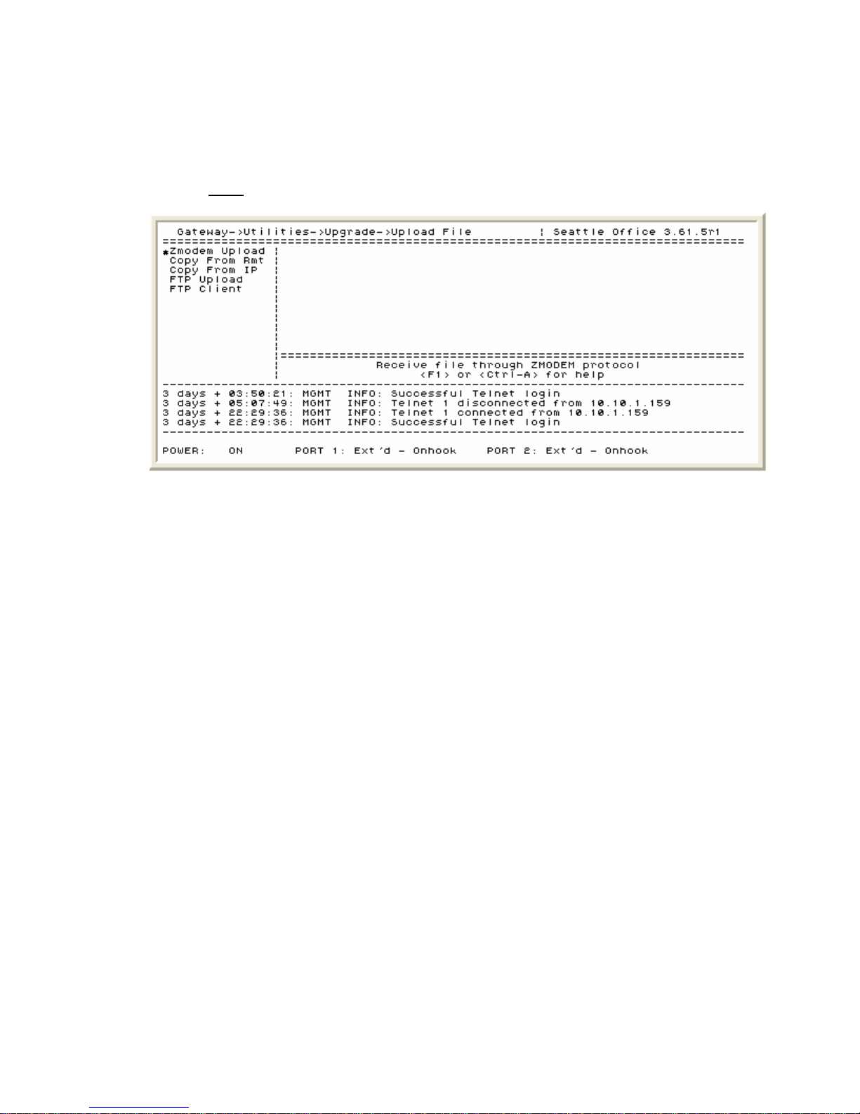
IP Dual Port PBXgateway and Remote System Administrator’s Guide
Via Zmodem Console Upload
Files to be uploaded using the Zmodem protocol must have extensions “.mab.”
1. Establish a direct serial connection to the unit.
Path: Gateway (Remote) ->Utilities->Upgrade->Upload File->Zmodem upload
99
Figure 55: Zmodem Upload
2. Select “[N]o” when asked if you want to optimize (the flash file system was optimized
in the file management process).
3. Press “[Y]es” to continue. A warning message is presented that you must not interrupt
the upload process.
4. When you see the message “Starting Zmodem Session – Hit Ctrl-X 5 times to cancel
the upload” go to the HyperTerminal menu bar and select “Transfer” and then “Send
File.”
5. Browse to the location of the file on your PC, highlight the file with the “.mab”
extension and select “Open.”
6. Make sure the protocol is set as Zmodem and press “Send” to begin the transfer.
7. Once the transfer has begun, HyperTerminal displays a status window indicating the
progress of the upload and inform you when it has been uploaded successfully.
8. The image may now be copied to multiple units if required. See the
Upload
section for details.
9. The unit is now ready to upgrade to the new software image. See the
Via In-Band
File Upgrade
section for details.
Document Number: M-4100-MUC Version: Rev AA © Copyright 2007 Citel plc All Rights Reserved
Page 100

IP Dual Port PBXgateway and Remote System Administrator’s Guide
Via In-Band Upload
You may transfer an image file across the in-band connection (link) when there is at least
one phone active over an IP connection between the PBXgateway and Remote.
Copy to Gateway or Remote
Use this method to copy an image file from the local PBXgateway to the Remote or from
the Remote to the PBXgateway.
1. On the Main Menu of the Management Console, choose “Gateway Login or Remote
Login” to login to the other unit. Press Enter.
100
2. Once logged in to the other unit, follow the steps in the
File Management section to
cleanup the Flash File System. Once the file management of the other unit is
complete log out of that unit and return to the original unit.
3. Select:
a)
Path: Utilities->File->Copy to Remote (or Copy to Gateway depending on what
unit is the source).
b) A dialog box appears showing how each port is connected
4. Select a port for transferring the file to and press Enter.
5. You will be prompted for a password, which is the password of the remote unit. If
configured, type it in now; otherwise just press Enter to continue.
6. A dialog box listing the files that can be transferred appears. Choose the file and
press Enter.
7. When asked to enter the destination filename, type the name of the file, leaving off the
“.mab” extension.
8. Press Enter to begin the transfer.
9. The time taken for an in-band transfer will vary depending on network activity. A
prompt “Copy Succeeded” will be presented when the transfer is complete.
10. Once completed, the image file is ready for upgrade. See the
File Upgrade section for
details.
Copy from Gateway or Remote
Use this method to copy an image file from the remote unit to the local PBXgateway or
Remote. Follow the steps in the
System prior to beginning.
1.
Path: Utilities->File->Copy From Gtwy (or Rmt)
Or,
Path: Utilities->Upgrade->Upload File->Copy From Gtwy (or Rmt)
2. A dialog box showing how each port is connecting back and forth between units
appears.
3. Select a port for transferring the file to and press Enter.
4. A password prompt will be presented. Hit Enter if there was no password otherwise
enter the password (if configured) and hit Enter.
5. A dialog box listing the files that can be transferred appears. Choose the file and
press Enter.
Document Number: M-4100-MUC Version: Rev AA © Copyright 2007 Citel plc All Rights Reserved
File Management section to cleanup the Flash File
 Loading...