

Citec DE38 Instruction Manual

DE38
Instruction Manual
Digital Differential Pressure Transmitter / Switch
Citec
Allée du plateau
Bât 2
ZI Nord
77200 TORCY
Tel : +33 (0) 1 60 37 45 08
Fax : + 33 (0) 1 64 80 45 18
Email : citec@citec.fr
www.citec.fr
1.2 Principles of Operation
The instrument uses a tough, flexible sensing diaphragm embedded between stiffening plates and
balanced by springs on either side. The diaphragm
is at zero position when pressures on either side of
the diaphragm are equal. Inequality of pressures
results in deflecting the diaphragm towards the lower pressure side until a new equilibrium determined
by the changed balance of forces is reached. Fastened to the center of the diaphragm is an axial rod,
the other end of which forms the moving core of an
inductive displacement transducer. The linear displacement of the core is proportional to the pressure difference across the diaphragm. This displacement is converted by the transmitter's electronic module to a standard electrical signal output.
An optional output signal can be slew rate limited,
spreaded, inverted and piecewise transformed nonlinearly by means of a table function.
2 Installation
The electronic module is mounted on a flat plate or
panel, for which it has 4 holes at the rear for selftapping screws 3.5mm.
A wall-mounting rear adaptor plate is available as
an option (s. Ordering Code).
The pressure transmitters are calibrated at the factory while mounted vertically, pressure ports downward. However, they can be mounted in any orientation. If they are installed with any orientation other
than vertical (pressure ports downward), the zero
point must be reset (s. section 5.3.2).
IP65 protection for the housing is guaranteed only if
suitable connecting cable is used.
If the instrument is intended for outdoor application,
we highly recommend using an adequate protective
housing (or at least a big enough shelter) as permanent protection against UV-radiation on the
membrane keyboard and against exposure of the
instrument to rain or snow.
1 Product Description and Functions
1.1 Block Schematic Diagram
NU 158
22/07/16

2.1 Process Connections
• Only qualified technicians authorized for this
type of work should undertake installation.
• Ensure that the mechanical configuration and
materials of construction of the instrument are
compatible with the process media.
• Ensure that process equipment and pressure
lines are at atmospheric pressure before making pressure connections.
• Pressure lines must have a downward gradient
throughout from the pressure instrument to the
process vessel/pipe. This is to prevent formation of air/gas pockets (for liquid applications) and liquid plugs (for air/gas applications).
• Pressure lines must be kept as short as possible and must not have short bends to avoid
measurement errors induced by pressure line
delays.
• The instrument should be provided with suitable
protection against pressure surges (e.g., snubber or pulsation damper).
• Ensure that process pressure is always less
than the specified safe pressure rating.
The instruments pressure ports are marked by ""
and "" symbols. For differential pressure applications the "" port must be connected to the higher
pressure and the "" port should be connected to
the lower pressure.
If the pressure transmitter is subjected to pressure
when it is started up, zero point checking and adjustment is not possible. In such cases, only electrical connections of the instrument should be made,
but not the pressure connections.
2.2 Elektroanschluss
• Only qualified technicians authorized for this
type of work should undertake installation.
• Switch off electrical power to the plant before
attempting electrical installation work of any
kind.
• Do not disconnect under voltage.
3-wire circuit
Connector 1: Supply voltage and output signal
For nominal supply voltage, the operating supply
voltage range and the maximum output signal loads
see chapter Specifications.
The signal ground line (-Sig) is internally connected
to the instrument ground (-Uo), and serves only as
an alternative ground connection for the output signal. This usually increases the noise margin.
Connector 2: Switch outputs
Switching output 1 (SP1) is configured by parameters R1A, R1E, R1D and R1F.
Switching output 2 (SP2) is configured by parameters R2A, R2E, R2D and R2F.
For more information see section 5.3.8.
SP1
no
SP2
com
SP2
no
SP1
com
Internally bridged
BN
WH
BU
BK
GN/YE
Signal -Sig
Supply –U
o
Signal +Sig
FE
Supply +U
o
p
Output
Evaluation
Input
+
-
-Sig /
+U
+Sig
-U
Output
230V
L
N
+Uo
-Uo
3 Starting Operation
All electrical supply, operating and measuring lines
and the pressure connections must have been correctly installed before commissioning. All supply
lines shall be arranged such that there are no mechanical forces acting on the device.
Check the leak-tightness of the pressure connections before commissioning.
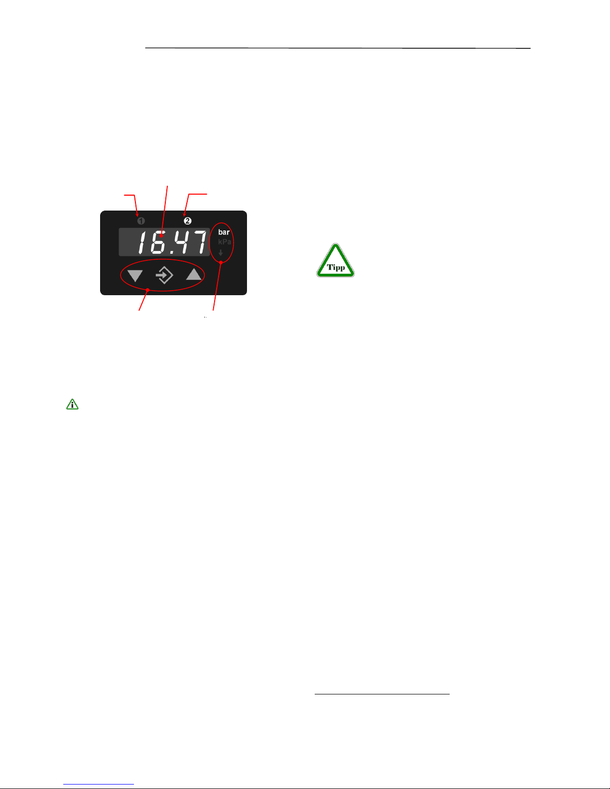
• The 3½ character LED display presents the
current differential pressure in normal operating
mode.
• The selected measuring unit is highlighted at
the right of the display.
The units represented on the screen may deviate from the actual design.
• Above the display, two LEDs symbolise
the condition of the switching outputs. As soon
as the switch is closed, the applicable LED
lights up.
3.2 Control keys
The control keys have the following functions:
ÿ
Menu down
Decrease value
û
Enter key
þ
Menu up
Increase value
By using the middle û key on the membrane keypad you can access the parameter menu (settings
mode). The display now shows the text ESc.
By using the right þ key you can move up within the
menu and can now select numerous parameters.
By pressing the left ÿ key, you can move down-
wards in the menu and finally get back to the ESC
parameter.
By pressing the middle û key you can call up a parameter.
Using the ÿ and þ keys, you can then set the parameter value.
In order to take on the adjusted parameter value,
press the û key.
All adjusted parameters are first then saved if you
leave the menu via the ESC parameter.
3.3 Configuration
For commissioning there is a multitude of setting
options for optimum adaptation of the device to the
measuring point and task at hand. This section covers these options step by step.
Depending on the device design available,1 some
menu points are not available. For example, all
characteristic curve functions are masked from the
menu if the device does not have a signal output.
The device can be completely set conveniently on the PC using a PC adaptor.
There all parameters are immediately
visible and accessible. In addition, the
complete configuration can be loaded, saved and
documented as a control print-out. Further guidelines on this program can be found in the documentation for this program (see accessories).
3.3.1 General
Put the device electrically into operation and ensure
that the device is initially depressurised (if necessary, disconnect the pressure connection lines).
In order to set a parameter, proceed as follows:
• Press the Enter û key in order to switch into the
menu. ESc will appear on the display.
• Use the ÿ þ arrow keys in order to select a pa-
rameter from the list.
• Press the Enter û key in order to call up the pa-
rameters.
• Use the ÿ þ arrow keys to set the required val-
ue.
• Use the Enter û key to save the value.
After you have set all the parameters, leave the
menu as follows:
2
• Using the ÿ þ arrow keys, set the ESc parame-
ter. You can find this both at the start and at the
end of the parameter list.
• Use the Enter û key to leave the menu.
3.3.2 Selection of pressure unit
First select the required pressure measuring unit.
The unit currently valid is highlighted on the right
next to the figure display. For setting, use the middle û key and then look using the right þ key for
1
With reference to the transmitter signal, voltage output, current
output etc.
2
Only when you leave the menu via the ESC parameter are the
set parameters valid.
3.1
Display Switching
Output1
Switching Output 2
3½ digits LED Display
Control keys
Measuring
 Loading...