


5.0 A/V Controller
Owner’s Manual
®

Staple or clip your original bill of sale here.
¤
2

Table of Contents
Introduction . . . . . . . . . . . . . . . . . . . . . . . . . . . . . . . . . . . . . . . . . . . . . . . . . . . . . . . . . . . . . . . 5
Safety Information . . . . . . . . . . . . . . . . . . . . . . . . . . . . . . . . . . . . . . . . . . . . . . . . . . . . . . . . . . 6
Quick-Start Instructions . . . . . . . . . . . . . . . . . . . . . . . . . . . . . . . . . . . . . . . . . . . . . . . . . . . . . . 9
Front Panel Controls & Indicators . . . . . . . . . . . . . . . . . . . . . . . . . . . . . . . . . . . . . . . . . . . . . . 13
Rear Panel Connections . . . . . . . . . . . . . . . . . . . . . . . . . . . . . . . . . . . . . . . . . . . . . . . . . . . . . . 15
Remote Control Operation . . . . . . . . . . . . . . . . . . . . . . . . . . . . . . . . . . . . . . . . . . . . . . . . . . . 18
System Installation . . . . . . . . . . . . . . . . . . . . . . . . . . . . . . . . . . . . . . . . . . . . . . . . . . . . . . . . . . 22
Input Connections . . . . . . . . . . . . . . . . . . . . . . . . . . . . . . . . . . . . . . . . . . . . . . . . . . . . . 22
Output Connections . . . . . . . . . . . . . . . . . . . . . . . . . . . . . . . . . . . . . . . . . . . . . . . . . . . 24
System Configuration . . . . . . . . . . . . . . . . . . . . . . . . . . . . . . . . . . . . . . . . . . . . . . . . . . . . . . . . 29
Speaker Selection and Placement . . . . . . . . . . . . . . . . . . . . . . . . . . . . . . . . . . . . . . . . . . 29
Initial Turn-On . . . . . . . . . . . . . . . . . . . . . . . . . . . . . . . . . . . . . . . . . . . . . . . . . . . . . . . 31
Speaker Setup . . . . . . . . . . . . . . . . . . . . . . . . . . . . . . . . . . . . . . . . . . . . . . . . . . . . . . . . 32
Program Setup . . . . . . . . . . . . . . . . . . . . . . . . . . . . . . . . . . . . . . . . . . . . . . . . . . . . . . . . 37
System Options . . . . . . . . . . . . . . . . . . . . . . . . . . . . . . . . . . . . . . . . . . . . . . . . . . . . . . .40
Editing Watch and Listen Lists . . . . . . . . . . . . . . . . . . . . . . . . . . . . . . . . . . . . . . . . . . . .43
Operating the Citation 5.0 . . . . . . . . . . . . . . . . . . . . . . . . . . . . . . . . . . . . . . . . . . . . . . . . . . . . 44
Turning On and Off . . . . . . . . . . . . . . . . . . . . . . . . . . . . . . . . . . . . . . . . . . . . . . . . . . . 44
Source Selection . . . . . . . . . . . . . . . . . . . . . . . . . . . . . . . . . . . . . . . . . . . . . . . . . . . . . . 45
Setting the Volume Level . . . . . . . . . . . . . . . . . . . . . . . . . . . . . . . . . . . . . . . . . . . . . . . . 46
Setting the Balance and Level Trims . . . . . . . . . . . . . . . . . . . . . . . . . . . . . . . . . . . . . . . . 47
Secondary Remote Controls . . . . . . . . . . . . . . . . . . . . . . . . . . . . . . . . . . . . . . . . . . . . . . 49
Surround Modes . . . . . . . . . . . . . . . . . . . . . . . . . . . . . . . . . . . . . . . . . . . . . . . . . . . . . . 50
Movie Modes vs. Music Modes . . . . . . . . . . . . . . . . . . . . . . . . . . . . . . . . . . . . . . . . . . . . 51
Surround Mode Definitions . . . . . . . . . . . . . . . . . . . . . . . . . . . . . . . . . . . . . . . . . . . . . . 52
Viewing System Status . . . . . . . . . . . . . . . . . . . . . . . . . . . . . . . . . . . . . . . . . . . . . . . . . . 54
Viewing the Digital Mode Status . . . . . . . . . . . . . . . . . . . . . . . . . . . . . . . . . . . . . . . . . . 54
Advanced Features . . . . . . . . . . . . . . . . . . . . . . . . . . . . . . . . . . . . . . . . . . . . . . . . . . . . . . . . . . 55
Customizing Surround Modes . . . . . . . . . . . . . . . . . . . . . . . . . . . . . . . . . . . . . . . . . . . . 55
Remote Zone . . . . . . . . . . . . . . . . . . . . . . . . . . . . . . . . . . . . . . . . . . . . . . . . . . . . . . . . 58
System Reset . . . . . . . . . . . . . . . . . . . . . . . . . . . . . . . . . . . . . . . . . . . . . . . . . . . . . . . . 59
3

Table of Contents (continued)
Troubleshooting Guide . . . . . . . . . . . . . . . . . . . . . . . . . . . . . . . . . . . . . . . . . . . . . . . . . . . . . . . 62
Appendix:
A. Factory Presets . . . . . . . . . . . . . . . . . . . . . . . . . . . . . . . . . . . . . . . . . . . . . . . . . . . . . 63
B. User Worksheets . . . . . . . . . . . . . . . . . . . . . . . . . . . . . . . . . . . . . . . . . . . . . . . . . . . . 66
Service Information . . . . . . . . . . . . . . . . . . . . . . . . . . . . . . . . . . . . . . . . . . . . . . . . . . . . . . . . . 68
Specifications . . . . . . . . . . . . . . . . . . . . . . . . . . . . . . . . . . . . . . . . . . . . . . . . . . . . . . . . . . . . . . 69
Figure Index . . . . . . . . . . . . . . . . . . . . . . . . . . . . . . . . . . . . . . . . . . . . . . . . . . . . . . . . . . . . . . 70
Limited U. S. and Canadian Warranty . . . . . . . . . . . . . . . . . . . . . . . . . . . . . . . . . . . . . . . . . . . 71
Citation is a registered trademark, and Dual Drive and 6-Axis are trademarks of Harman International.
Dolby, Pro Logic and AC-3 are registered trademarks of Dolby Laboratories Licensing Corp.
DTS is a registered trademark of Digital Theater Systems, Inc.
Citation
Madrigal Audio Laboratories, Inc.
P.O. Box 781
Middletown, CT 06547
Manufactured in USA
A Harman International Company
©1998 Madrigal Audio Laboratories, Inc. Printed in USA
®
4
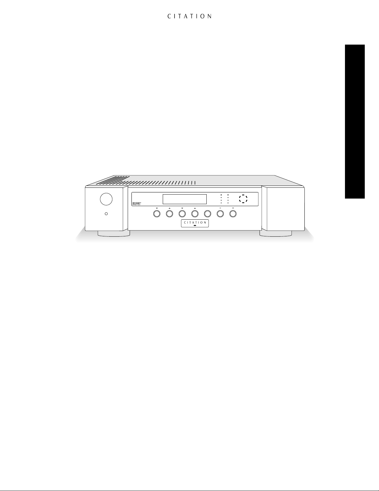
Introduction
5.0 AV Controller
Watch Listen Mute Volume
Standby
On / Off
CLIP
RIGHTLEFT
+10dB
0dB
-10dB
FRONT
BACK
LEFT RIGHT
Prog 8 : DVD
Dolby Digital Vol=35
Congratulations! As the owner of a Citation 5.0 A/V Controller, you have a unique product at your
command. Combining elegant, sculpted metal panels, the latest state-of-the-art circuit design, onboard Dolby®Digital decoding and Madrigal Audio Laboratories heritage of audio excellence, the
Citation 5.0 will bring many years of enjoyable listening to your music or home-theater system.
In order to fully enjoy the performance capabilities of your new 5.0, please take a few minutes to
read this Owner’s Manual. It contains important information that will help you to properly configure
your Controller for operation with the rest of the equipment in your system.
If you have any questions about this product, its installation or operation, please contact your retailer
or custom installer. They are your best source of local information. Should you need additional
information or assistance, the number for Citation Customer Support is 860-346-0896.
Introduction
5
Important Safety Information
Safety Information
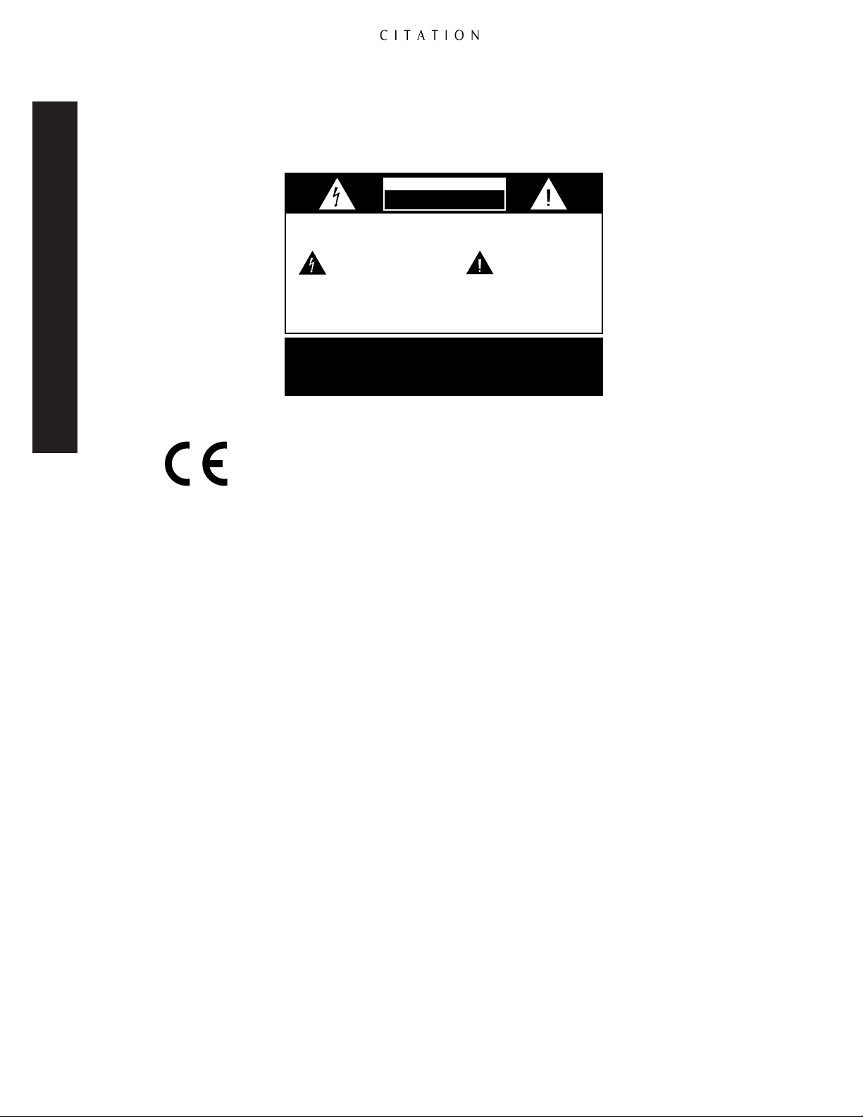
CAUTION
RISK OF ELECTRIC SHOCK
DO NOT OPEN
CAUTION:
presence of uninsulated “dangerous voltage”
within the product’s enclosure that may be of
sufficient magnitude to constitute a risk of
electric shock to persons.
ATTENTION:
LAME LA PLUS LARGE DE LA FICHE DANS LA BORNE CORRESPONDANTE DE
TO REDUCE THE RISK OF ELECTRIC SHOCK, DO NOT REMOVE
COVER (OR BACK). NO USER-SERVICEABLE PARTS INSIDE. REFER
SERVICING TO QUALIFIED SERVICE PERSONNEL.
The lightning flash with arrowhead
symbol, within an equilateral triangle, is
intended to alert the user to the
WARNING:
TO REDUCE THE RISK OF FIRE OR ELECTRIC SHOCK,
DO NOT EXPOSE THIS APPLIANCE TO RAIN OR MOISTURE.
CAUTION:
TO PREVENT ELECTRIC SHOCK, MATCH WIDE
BLADE OF PLUG TO WIDE SLOT, FULLY INSERT.
POUR EVITER LES CHOCS ELECTRIQUES, INRODUIRE LA
LA PRISE ET POUSSER JUSQU'AU FOND.
The exclamation point within an
equilateral triangle is intended to
alert the user to the presence of
important operating and maintenance
(servicing) instructions in the literature
accompanying the appliance.
Marking by the “CE” symbol (shown left) indicates compliance of this device with the
EMC (Electromagnetic Compatibility) and LVD (Low Voltage Directive) standards of
the European Community.
Verify Line Voltage Before Use
Your new Citation 5.0 A/V Controller has been factory preset for a specific line voltage: 110-120
volts for North America or 220-240 volts in most other parts of the world. Connection to a line
voltage other than that for which it is intended may create a safety and fire hazard.
If you have any questions about the voltage requirements for your specific model, or about the line
voltage in your area, contact your selling dealer before plugging the unit into a wall outlet.
Do Not Use Extension Cords
To avoid safety hazards, use only the power cord supplied with your unit. If a replacement cord is
used, make certain that it is of similar gauge. We do not recommend the use of extension cords with
this product. As with all electrical devices, do not run power cords under rugs or carpets or place
heavy objects on them. Damaged power cords should be replaced immediately by a qualified service
center, using cords meeting factory specifications.
Handle the AC Power Cord Gently
When disconnecting the power cord from an AC outlet always pull the plug, never pull the cord.
If you do not intend to use the 5.0 for any considerable length of time, disconnect the plug from
the AC outlet.
Do Not Open the Cabinet
There are no user-serviceable components inside this product. Opening the cabinet may present a
shock hazard, and any modification to the product will void your warranty. If water, or any metal
object, such as a paper clip, wire or a staple, accidentally falls inside the unit, disconnect it from
the AC power source immediately and consult an authorized service station.
6

Installation Location
• To ensure proper operation and to avoid the potential for safety hazards, place the unit on a
firm and level surface. When placing the unit on a shelf, be certain that the shelf and mounting
hardware can support the weight of the product.
• Make certain that proper space is provided both above and below the unit for ventilation. If this
product will be installed in a cabinet or other enclosed area, make certain that there is sufficient
air movement within the cabinet. Consult with your dealer or installer for more information.
• Do not place the unit directly on a carpeted surface.
• Avoid installing the 5.0 in extremely hot or cold locations, or in an area that is exposed to direct
sunlight or heating equipment.
• Avoid moist or humid locations.
• Do not obstruct the ventilation slots on the top of the unit, or place objects directly over them.
Cleaning
When the unit gets dirty, wipe it with a clean, soft, dr y cloth. If necessary, wipe it with a soft cloth
dampened with mild soapy water, then a fresh cloth dampened with clean water. Wipe dry immediately with a dry cloth. NEVER use benzene, thinner, alcohol or any other volatile cleaning agent. DO
NOT use abrasive cleaners, as they may damage the finish of metal parts. Avoid spraying insecticide
near the unit.
Safety Information
Moving the Unit
Before moving the unit, disconnect any cables that connect the 5.0 to other components. Make
certain that the AC power cord is unplugged from the wall outlet.
Important Information for the User
Note: This equipment has been tested and found to comply with the limits for a Class-B digital
device, pursuant to Part 15 of the FCC Rules. The limits are designed to provide reasonable
protection against harmful interference in a residential installation. This equipment generates,
uses and can radiate radio frequency energy and, if not installed and used in accordance with
the instructions, may cause harmful interference to radio communication. However, there is no
guarantee that harmful interference will not occur in a particular installation. If this equipment
does cause harmful interference to radio or television reception, which can be determined by
turning the equipment off and on, the user is encouraged to try to correct the interference by one
or more of the following measures:
• Reorient or relocate the receiving antenna.
• Increase the separation between the equipment and receiver.
• Connect the equipment into an outlet on a circuit different from that to which the receiver
is connected.
• Consult your dealer or an experienced radio/TV technician.
7

Safety Information
This device complies with Part 15 of the FCC Rules. Operation is subject to the following two
conditions: (1) this device may not cause harmful interference, and (2) this device must accept
interference received, including interference that may cause undesired operation.
Note: Changes or modifications may cause this unit to fail to comply with Part 15 of the FCC
Rules and may void the user’s authority to operate the equipment.
Unpacking
The carton and shipping materials used to protect your new 5.0 during shipment were specially
designed to cushion it from shock and vibration. We suggest that you save the carton and packing
materials for use in shipping if you move or should the unit ever need repair.
To minimize the size of the carton in storage, you may wish to flatten it. This is done by carefully
slitting the tape seams on the bottom and collapsing the carton down to a more two-dimensional
appearance. Other cardboard inserts may be stored in the same manner. Packing materials that
cannot be collapsed should be saved along with the carton in a plastic bag.
If you do not wish to save the packing materials, please note that the carton and other sections of the
shipping protection are recyclable. Please respect the environment and discard those materials at the
local recycling center.
Typographic Conventions
In order to help you use this manual with diagrams of the remote control, front panel controls,
rear panel connections and on-screen menus, certain conventions have been used.
Example – (bold type) indicates a specific remote control or front panel button, or rear panel
connection jack.
Example – (OCR type) indicates a message that is visible through the on-screen menu system or
on the front panel information display.
1 – (Number in a square) indicates a specific front panel control.
¡ – (Number in a circle) indicates a rear panel connection.
å – (Letter in a circle) indicates a button on the main portion of the remote control.
A – (Letter in a square) indicates a button under the sliding panel on the lower portion of the
remote control.
References to “OSD” indicate a display message that appears through the on-screen menu system.
References to “FPD” indicate a display message that appears in the front panel information display.
A complete index of OSD and FPD figures appears on page 70.
8

Quick-Start Instructions
Congratulations on your purchase of a Citation 5.0 A/V Controller. You now own the heart of a
home-entertainment system capable of sound reproduction that rivals the finest concert hall or the
most modern movie theater.
In order to get the maximum benefit from your new Controller, we strongly suggest that you take
the time to carefully read this Owner’s Manual. It contains a wealth of information that will help you
to properly install, calibrate and operate the Citation 5.0.
We realize, however that you may be anxious to get into action, so the following steps will provide
the minimum instructions needed to get things hooked up and “on the air.” Please follow the
directions carefully to avoid any possibility of damage to other components in your system.
Once you have your Controller connected, we urge you to read through the rest of this Owner’s
Manual so that your system may be adjusted for optimal performance. That small investment of
your time will yield dividends in the form of many hours of listening enjoyment.
Equipment Required for Quick-Start Installation:
Citation 5.0 A/V Controller
Left/Right Front Channel Speakers
Center Channel Speaker
Two Surround Speakers
Five Channels of Amplification
Quick-Star t Instructions
Source Equipment (DVD,VCR, Laser Disc, CD, etc.)
Interconnect and Speaker Cables
Recommended Optional Equipment:
Subwoofers (Powered or Passive)
External Amplification for the Subwoofer, if required
Video Display (Direct View Monitor/Receiver or Video Projector)
Dual Drive™Dipoles or Additional Surround Speakers
Additional Amplification for the Surround Speakers
9
SIDE BACKREC A CENTERFRONT
STEREO
SUB
DIGITAL AUDIO INPUTS
ANALOG AUDIO INPUTS
1
L
R
2 3 4
7 8 9 10 1211
5 6
L
R
REMOTE
ZONE
TRIGGERS
TRIG 1 TRIG 2IR IN
IN
3IN 2IN1
IN 4 IN 5 IN 6 IN 2
IN 1
CITATION BUS
115V ~60Hz
75 WATTS
AVIS: RISQUE DE CHOC ELECTRIQUE - NE PAS OUVRIR
CAUTIONCAUTION
RISK OF ELECTRIC SHOCK
DO NOT OPEN
WARNING:
TO REDUCE THE RISK OF FIRE
OR ELECTRIC SHOCK DO NOT EXPOSE THIS
EQUIPMENT TO RAIN OR MOISTURE. DO NOT
REMOVE COVER. NO USER-SERVICEABLE
PARTS INSIDE. REFER SERVICING TO QUALIFIED
SERVICE PERSONNEL.
SERIAL NUMBER
COMPOSITE VIDEO
S – VIDEO
MONO SUB
AUDIO OUTPUTS
Manufactured under license from Dolby Laboratories Licensing Corporation. "Dolby", "AC-3",
"Pro Logic" and the Double-D symbol are trademarks of Dolby Laboratories Licensing
Corporation. Copyright 1992 Dolby Laboratories, Inc. All rights reserved.
Additionally licensed under U.S. patent numbers 5,172,415; 5,263,087; 5,307,415; 5,280,528;
5,339,363; 5,295,189; 4,932,059; 5,428,687: 5,504,819 and patents pending.
5.0 AV Controller
Manufactured in the USA
REC ARMT ZONE
AUXMAIN
+
VDC
1 2 3
GND
4
REC A
RMT ZONE
AUX
MAIN
OUT
®
NRTL /C
LR110480
CSA E65
OUT
Connect to output
of composite
video sources
Connect to coaxial
digital audio output
of A/V sources, DVD,
HDTV, CD, etc.
Connect to optical
digital audio output
of A/V sources, DVD,
HDTV, CD, etc.
Connect to
composite
video input of
main monitor
Connect to
composite
video input
of a VCR
Connect to
S-Video input
of main monitor
Connect to
S-Video input
of VCRs
Connect to
analog audio
output of A/V
sources, CD,
tuner, etc.
Connect to
audio input
of VCR or
audio recorders
Connect to
analog audio
input of a
multiroom-audiodistribution system
or a 2nd audio
recorder or VCR
Connect to
inputs of audio
power amplifiers
Connect to
“DC IN” remote
jack on compatible
Citation power
amplifiers
Connect to voltagecompatible screen
control systems or
other compatible
low-voltage controlled
products
Connect AC Power
to non-switched
wall outlet
Connect to S-Video
output sources
Connect to
composite video
input of a multiroomvideo-distribution
system or a 2nd VCR
Connect to
composite video
output of a
multiroom-videodistribution system
or a 2nd VCR
Quick-Start Connection and Setup
Quick-Start Instructions
Note: These are the minimum hook-up connections required to install a Citation 5.0. In order to
obtain the maximum benefit from the 5.0’s many features and to ensure correct connections,
please follow the detailed connection, setup and configuration instructions in this manual.
1. First, please make certain that ALL electronic equipment, including any amplifiers, source equipment and, of course, your Citation 5.0 are unplugged from AC power outlets. Many audio/video
devices contain automatic turn-on circuits which may be triggered during the setup process.
Disconnecting them until they are required is a good safety habit that will also reduce the possibility
of damage to your components due to unintended turn-on.
2. Using high-quality interconnect cables, connect the video, analog audio and digital audio outputs
of your source equipment to the Citation 5.0 according to the locations shown on the chart on the
next page. While the great flexibility of the 5.0 makes it possible to connect source gear in an almost
unlimited number of combinations, using these presets will simplify getting started. You may always
add additional equipment or change connection locations later, following the instructions found in
this manual. When connecting tape recorders, remember to use the “Play/Out” jacks on the recorder
for connection to the 5.0’s inputs.
10
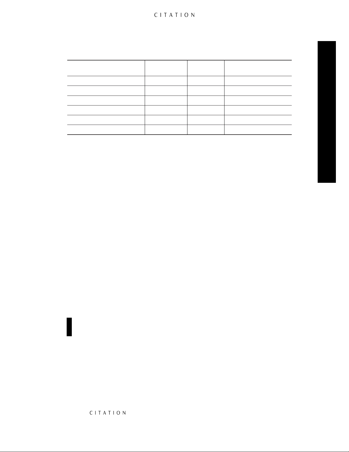
Analog Digital
Video Audio Audio
Source Device Connection Connection Connection
Laser Disc Player Composite 1 Analog 1 Digital 7
(from RF Demodulator)
VCR Composite 2 Analog 2 None
Satellite Receiver Composite 3 Analog 3 Digital 8
Tuner None Analog 4 None
CD Player or External D/A None Analog 5 Digital 10
CD Changer or External D/A None None Digital 11
DVD Player Composite 4 None Digital 9
3. Connect the Rec A Audio Output of the 5.0 to the “Rec/In” input of the audio recorder or VCR
that will be used to record the output of the 5.0. Connect the Rec A Video Output to the composite
video input of a VCR that will be used to record the output of the 5.0.
4. Connect the Main Composite Video Output on the 5.0 to the Video In jack on your TV monitor
or other video display device. A connection from the Main S-Video Output on the 5.0 to the
S-video input on your video display may also be made if you will use S-video sources at a later time.
5. Using high-quality audio interconnect cables, connect the Audio Outputs of the 5.0 to the
matching input connection on your amplifier. Note that the 5.0’s preset default is for Citation
or Fosgate•Audionics Dual Drive dipole surround speakers. If you are using standard surround
speakers you will need to make an adjustment at the Speaker Setup menu, as detailed on pages
32–33 of this manual.
Quick-Star t Instructions
6. Connect the Subwoofer Outputs to the line-level input of powered subwoofers, or to the amplifier that will power passive subwoofers. Note that the 5.0 is shipped for use with stereo subwoofers
as a factory default. If you are using stereo subwoofers, be certain to connect them to the Sub
Outputs
at the far side of the output jack field. If you are using only one subwoofer, connect it to
the Mono Sub jack. If one or no subwoofers are installed, please note that you will have to make an
adjustment to the Speaker Setup menu, as described on page 34 of this manual.
7. If a Citation power amplifier, or other compatible power amplifier with 12-volt turn-on trigger
circuits will be used, connect the Trig 1 Trigger jack on the 5.0 to the Trigger Input on the amplifier
using a connection cord with mono 3.5mm mini-plugs at both ends. Follow the switch setting
instructions for the amplifiers, if any, as detailed in the amplifier owner’s manual.
Important Note: To avoid unwanted hum and noise, be careful to keep audio connections, par-
ticularly those for amplifiers, separated from AC power cords. Do not coil extra lengths in either
audio interconnects or speaker cables.
8. Connect all speakers to the amplifiers in accordance with the instructions supplied by the manufacturers. Make certain that all speaker connections are made with special attention to proper polarity.
9. Install four AAA batteries in the remote. Open the battery cover on the back of the remote by
sliding the cover down and towards you. Be careful to install the batteries so that they match the
polarity (+ and –) indications inside the battery compartment.
10. Connect all devices, including the 5.0, to their AC power source.
11. Press the small On/Off button on the front panel of the 5.0 (below the large Standby button)
in until it clicks and catches. It will remain in and flush with the unit’s front panel. Note that
the word will briefly flash in blue and then go out, and a small green indicator
will illuminate.
11

12. If you will be using a video display, turn it on at this point, and make certain that it is switched
to the video input that matches the connection jack used.
13. To turn on the 5.0, press either the Watch button on the front panel or remote if you wish to use
the video sources, or the Listen button if you wish to use one of the audio-only sources. The green
indicator on the front panel will go out, and be replaced by a soft blue illumination behind the word
on the front panel. The two-line front panel display will also illuminate. A sign-on
menu will appear on the video display for a few seconds, followed by a Watch Programs or
Listen Programs listing.
• If you are using a Citation power amplifier, or another compatible amplifier connected to the
Trig 1 Trigger jack, it will receive a turn-on signal when the Watch or Listen button is pressed.
Note that with many amplifiers there will be a short, intentional delay between the turn-on signal
and when the amplifier sends signals to the speakers. This is a normal function designed to prevent
damage to your speakers.
Quick-Star t Instructions
• If you are using a conventional amplifier not controlled by the 5.0’s trigger output, turn it on at
least 10 seconds AFTER the 5.0 is turned on.
14. When the Watch or Listen Programs lists are on the screen, press the⁄or¤button on
the remote until the desired source is highlighted. Then press the Watch or Listen button again to
select that source.
15. The selected source will now be heard through your system, and an informational display will
appear at the bottom of your video display. You may adjust the volume at any time by using the
Vol – or Vol + buttons on the remote or front panel, or temporarily silence the speaker output by
pressing the Mute button. To select another source, press the Watch or Listen button and follow the
instructions in Step 14, above.
16. When you are finished with a listening session, press the Standby button on the front panel or
in the upper right corner of the remote. The front panel display and blue will go
out, and the green indicator will come back on, to remind you that the 5.0 is in the Standby mode,
ready to work again whenever you press the Watch or Listen buttons.
At this point you are “on the air!” Sit back and enjoy the best in home entertainment.
Of course, this is only the tip of the iceberg. Although you have successfully completed a minimal
installation we strongly recommend that you take time to read the rest of this Owner’s Manual
thoroughly. It will show you how to use the many features, modes and controls that are a vital part
of the Citation 5.0. Correct setup and installation is important to optimizing the sound quality of
your new controller, and will also make it easier to operate. A few minutes spent reading this manual
and making certain that your 5.0 is set up to meet the individual characteristics of your system and
listening room will enable your 5.0 to deliver the optimum performance of which it is capable.
12
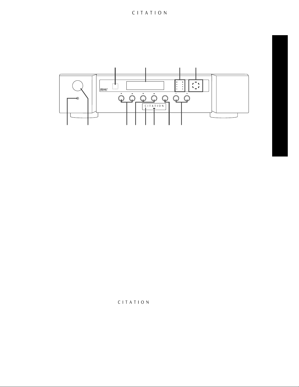
Front Panel Controls and Indicators
Front Panel Controls & Indicators
@
Prog 8 : DVD
Standby
On / Off
5.0 AV Controller
1 2
1 Master Power Button
2 Standby Button
3 Watch Selectors
4 Listen Selectors
1
Master Power Button: This button is the main power control for the 5.0. Press it in until the tip
Dolby Digital Vol=35
Watch Listen Mute Volume
3 4 5 6 7 8
! ) 9
5 Power Indicator
6 Standby LED
7 Mute Button
8 Volume Control
CLIP
+10dB
0dB
-10dB
FRONT
LEFT RIGHT
BACK
RIGHTLEFT
9 Steering Logic Display
) Level Indicators
! Information Display
@ Remote Sensor
of the button is flush with the front panel to turn the unit on. For normal use, this button should
remain in the ON position, with the Standby button or remote control used for turn on/off in normal use. To turn the unit fully off, press the button in so that the stem pops out to the extended
position. When the button is in the OFF position, the 5.0 will not respond to commands from the
remote control or external control systems.
2
Standby Button: Press this button lightly to turn the 5.0 on or off. Note that in order for this
button to operate the 5.0, the Master Power button 1must be in the ON position, as indicated
by the appearance of the green Standby LED 6.
3
Watch Selectors: Press these buttons to select an input from the Watch List. The first press of
either Watch button will display the last input program selected from the list, and subsequent presses
of the button will scroll up or down through the list of choices. When the desired input program is
displayed, it will take effect after a brief pause. For information on programming the Watch List, see
page 43.
4
Listen Selectors: Press these buttons to select an input from the Listen List. The first press of
either Listen button will display the last input program selected from the list, and subsequent presses
of the button will scroll up or down through the list of choices. When the desired input program is
displayed, it will take effect after a brief pause. For information on programming the Listen List, see
page 43.
5
Power Indicator: The word illuminates in blue when the 5.0 is ON and in full
operation. When this indicator is not lit, but the Standby LED 6below is green, the unit is in the
Standby mode. When both indicators are dark, the Master Power button 1is in the OFF position,
or the unit is not connected to a live AC power source.
6
Standby LED: When this indicator glows green, the 5.0 is in the Standby mode, and it is ready to
be turned ON or OFF when either the Standby
2 å
, or the Watch
3 ç
or Listen
4 ƒ
buttons
are pressed. When the Standby LED is out, but the Power Indicator 5is illuminated in blue, the
unit is ON. When both of these indicators are dark, the 5.0 has either been turned off with the
Master Power button
1
or is not plugged into a live AC power source.
13

7
Mute Button: Press this button to temporarily reduce or silence the audio output. Press the button
again, or change the volume level to return to normal operation. Note that when the Mute function
is activated, the level at the Record Outputs£and Remote Zone™will remain uninterrupted.
When Mute is engaged, a reminder message will appear in the on-screen display (see figures OSD-20
and OSD-21 on page 47) and the word Mute will replace the volume level indication in the
Information Display
!
. The actual level for the system when the Mute function is engaged may be
set through the System Options Menu (see page 40).
8
Volume Control: Press these buttons to raise (+) or lower (
indications are provided through both the on-screen display (see figure OSD-19 on page 47) and the
front panel Information Display!.
9
Steering Logic Display: The indicators in this display provide a visual indication of where the
5.0 is directing signals for the various audio channels. It is normal for these indicators to flash
during operation.
)
Level Indicators: These two columns of LEDs provide a four-step display of the left- and right-
channel-input level to the 5.0. Note that it is normal for these lights to flash on and off during operation as they react to the changing level of your program material. If there is no movement in this
Front Panel Controls & Indicators
display, it is a sign that the input level may need adjustment, or that there is a problem with the
playback source or interconnect cables. Note that the input level may only be adjusted for analog
audio sources, and if they constantly register at the “+10dB” or “Clip” markings, the input needs to
be reduced. See page 38 for more information on adjusting the input levels.
!
Information Display: This two-line display is your window into the status of the Citation 5.0. In
normal operation, the display shows the input program number and source name in use on the top
line, and the current surround mode and system volume level on the bottom line. When adjustments
are being made for setup or re-configuration of the unit’s operating system or parameters, the twoline display will indicate the options and instructions needed to make the required choice.
@
Remote Sensor: This area contains the sensor that receives commands from the 5.0’s infrared
remote control. Make certain that cabinets, smoked glass doors or other objects that may interfere
with the line of sight from the remote do not block it.
–
) the main system volume. Volume
14
Rear Panel Connections
SIDE BACKREC A CENTERFRONT
STEREO
SUB
DIGITAL AUDIO INPUTS
ANALOG AUDIO INPUTS
1
L
R
2 3 4
7 8 9 10 1211
5 6
L
R
REMOTE
ZONE
TRIGGERS
TRIG 1 TRIG 2IR IN
IN
3IN 2IN1
IN 4 IN 5 IN 6 IN 2
IN 1
CITATION BUS
115V ~ 60Hz
75 WATTS
AVIS: RISQUE DE CHOC ELECTRIQUE - NE PAS OUVRIR
CAUTIONCAUTION
RISK OF ELECTRIC SHOCK
DO NOT OPEN
WARNING:
TO REDUCE THE RISK OF FIRE
OR ELECTRIC SHOCK DO NOT EXPOSE THIS
EQUIPMENT TO RAIN OR MOISTURE. DO NOT
REMOVE COVER. NO USER-SERVICEABLE
PARTS INSIDE. REFER SERVICING TO QUALIFIED
SERVICE PERSONNEL.
SERIAL NUMBER
COMPOSITE VIDEO
S – VIDEO
MONO SUB
AUDIO OUTPUTS
Manufactured under license from Dolby Laboratories Licensing Corporation. "Dolby", "AC-3",
"Pro Logic" and the Double-D symbol are trademarks of Dolby Laboratories Licensing
Corporation. Copyright 1992 Dolby Laboratories, Inc. All rights reserved.
Additionally licensed under U.S. patent numbers 5,172,415; 5,263,087; 5,307,415; 5,280,528;
5,339,363; 5,295,189; 4,932,059; 5,428,687: 5,504,819 and patents pending.
5.0 AV Controller
Manufactured in the USA
REC ARMT ZONE
AUXMAIN
OUT
+
VDC
1 2 3
GND
4
REC A
RMT ZONE
AUX
MAIN
OUT
®
NRTL /C
LR110480
CSA E65
›
¡
™£¢∞§¶•
ª
‚
⁄
‹
fi
fl
‡
a
bc·
°
df
eg
Caution: Never make or remove any connections to the Citation 5.0 with the Master Power
button 1in the “ON” position. It is also good practice to make certain that any power amplifiers connected to the 5.0 are also turned off when making or removing any connections. This
eliminates the risk of possible damage to your speakers or other system components.
When making connections to the Citation 5.0 make certain that the input plug is firmly seated in
the input jack. This prevents intermittent connections which may interfere with performance.
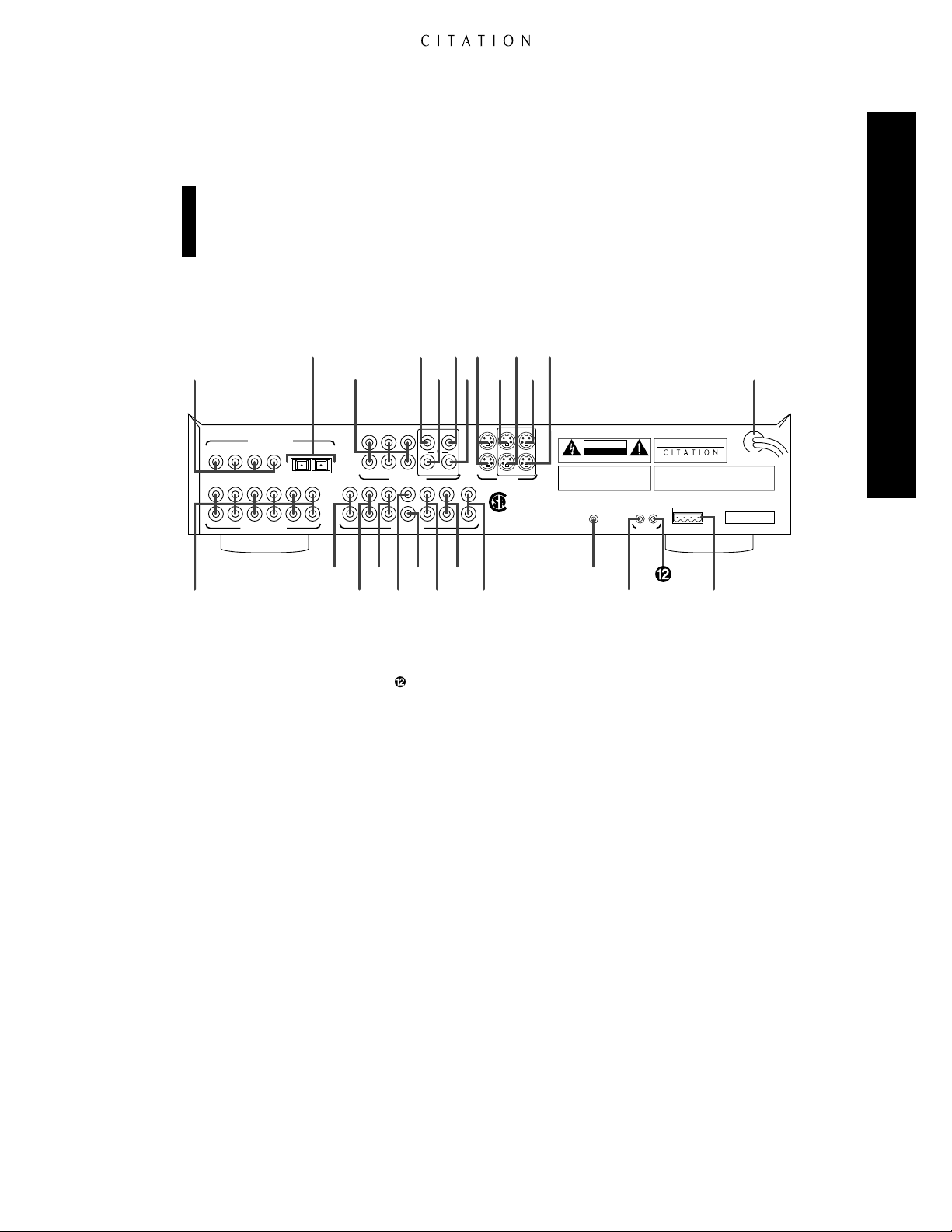
Rear Panel Connections
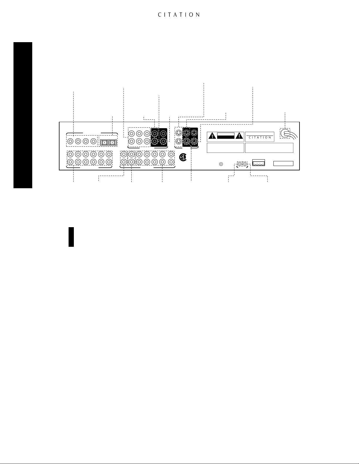
¡ Analog Audio Inputs
™ Remote Zone Outputs
£ Record Outputs
¢ Front Channel Audio Outputs
∞ Center Channel Audio Output
§ Mono Subwoofer Output
¶ Side Channel Outputs
• Back Channel Outputs
ª Stereo Subwoofer Outputs
¡
Analog Audio Inputs: Connect the output of analog audio devices to these inputs. Note that the
‚ IR In
⁄ Trigger 1 Output
Trigger 2 Output
‹ Citation Bus Control Port
› Power Cord
fi S-Video Record Output
fl S-Video Auxiliary Output
‡ S-Video Remote Zone Output
° S-Video Main Output
· S-Video Inputs
a Record A Composite Video Output
b Auxiliary Composite Video Output
c Composite Video Remote Zone Output
d Main Composite Video Output
e Composite Video Inputs
f Optical Digital Audio Inputs
g Coax Digital Audio Inputs
left channel input is on top, and the right channel input is on the bottom. Once a source has been
connected, it may be assigned to any of the twelve Program Settings using the Program Menu (see
page 37). In this menu the various parameters of the input may be established, including a source
name and other system options.
™
Remote Zone Outputs: These outputs are used to feed an optional, external power amplifier
for feeds to a remote zone location. The assignment of specific sources to an individual Remote
Zone input number is done through the Remote Zone Menu (see page 58). The actual selection
of the Remote Zone input is made by pressing the Remote Zone Indicator buttons Ron the
remote control.
£
Record Outputs: These jacks provide an output for connections to the “REC IN” jacks of a
recording device such as a VCR, cassette recorder, DAT, MiniDisc, or reel-to-reel recorder. The
signal output through these jacks is always identical to the source program selected for the main
input to the 5.0.
15

¢
Front Channel Audio Outputs: Connect these jacks to the inputs of the audio power amplifier
feeding the front left and right speakers.
∞
Center Channel Audio Output: Connect this jack to the input of the audio power amplifier
feeding the center channel speaker.
§
Mono Subwoofer Output: Connect this jack to the line-level mono input of a powered subwoofer,
or the input of an audio amplifier driving a single passive subwoofer.
¶
Side Channel Outputs: If Citation or other Dual Drive speakers are used, connect these jacks to
the amplifier driving the side channel speaker inputs. If separate side channel speakers are mounted
on the left and right walls of the room, connect these jacks to the amplifier providing power to those
speakers.
•
Back Channel Outputs: If Citation or other Dual Drive speakers are used, connect these jacks
to the amplifier driving the back channel speaker inputs. If separate speakers are mounted on the rear
wall of the listening room, connect the jacks to the amplifier providing power to those speakers.
Rear Panel Connections
ª
Stereo Subwoofer Outputs: When two subwoofers are installed, connect the outputs of these
jacks to the input of the powered subwoofers or to the input of the audio power amplifier driving
passive subwoofers.
‚
IR In: An external infrared sensor may be connected to this jack for use in sending remote com-
mands to the 5.0 when the front panel IR Sensor@is blocked, or when a remote sensor is used to
control the input and volume from a remote zone location. Selection of the control path for a sensor
connected to this jack is controlled via the IR Mode setting on the System Options Menu (see
page 40).
⁄
Trigger 1 Output: This jack may be used to supply a trigger control voltage for Citation audio
power amplifiers or other compatible devices such as projection screens or automatic blinds designed
to accept low-voltage on/off control signals. Programming the triggers with regard to the commands
they respond to (e.g., Power, Mute or Display Dim) is controlled through the Program Triggers
line on the System Options Menu (see pages 41–42). Setup for the action of the trigger when a
specific input is used is programmed through the Programs Setup Menu (see page 37).
Trigger 2 Output: The function of this trigger is identical to Trigger 1, except that it is typically
used to control external devices such as screens, blinds or lighting controls. Trigger 1 is typically used
for control of audio power amplifiers. Of course, the decision of the devices controlled is entirely
user-selectable.
‹
Citation Bus Control Port: This plug is provided to permit operation of the Citation 5.0 by
computers or optional wired remote control or home automation systems. The use of this control
port requires additional, optional software and it is strongly recommended that a Citation dealer be
consulted before any connections are made to this port.
›
Power Cord: Connect this plug to an unswitched AC power outlet.
fi
S-Video Record Output: Connect this jack to the S-video input of an S-video device to record the
selected input source when S-video is present.
fl
S-Video Auxiliary Output: This jack provides an additional S-video output connection for the
input source selected for the main viewing room.
‡
S-Video Remote Zone Output: This jack provides an S-video signal for the remote zone
location when an S-video source is selected using the Remote Zone Indicator buttons Ron the
remote control.
16

°
S-Video Main Output: Connect this jack to the main video display device that will be used to
view the output of the source selected by the 5.0.
·
S-Video Inputs: Connect the output of S-video sources to these input jacks. Once the inputs have
been connected, they may be assigned to any of the 5.0’s program profiles using the Programs
Setup Menu (see page 37).
Important Note on S-Video Sources: The 5.0 does not convert standard, composite video input
signals into S-video outputs. In order for a video signal to appear at any of the S-video outputs,
the input program must contain S-video source.
a
Record A Composite Video Output: Connect this jack to the standard video “REC IN” jack of a
VCR to record the input selected by the 5.0.
b
Auxiliary Composite Video Output: This jack provides an additional composite video output
connection for the source selected for the main viewing room.
c
Composite Video Remote Zone Output: This jack provides a standard, composite video signal
for the remote zone location. This input is selected by using the Remote Zone Input buttons Ron
the remote control.
d
Main Composite Video Output: Connect this jack to the composite video input of the TV set,
video monitor, projection television or other video display device that will be used in the main
viewing location.
e
Composite Video Inputs: Connect the output of composite video sources to these input jacks.
Once the inputs have been connected, they may be assigned to any of the 5.0’s program profiles
using the Programs Setup Menu (see page 37).
Rear Panel Connections
f
Optical Digital Audio Inputs: Connect the optical (TosLink) digital audio output of audio
sources to these jacks. Once the inputs have been connected, they may be assigned to any of the
5.0’s program profiles using the Programs Setup Menu (see page 37).
g
Coax Digital Audio Inputs: Connect the coax digital audio output of audio sources to these jacks.
Once the inputs have been connected, they may be assigned to any of the 5.0’s program profiles
using the Programs Setup Menu (see page 37).
17
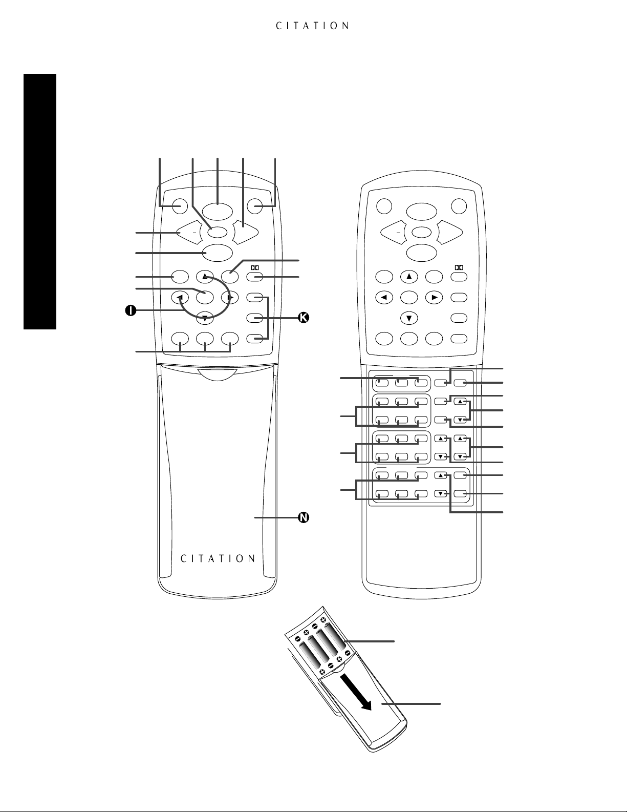
Remote Control Operation
Citation 5.0 Remote Control
Remote Control Operation
∫
ƒ
©
˙
∆
≠
Display
Cncl Bal
Cust 1
Menu
Cust 2
ç å∫∂
Watch
Mute
Listen
Cust 3
Vol +Vol
Standby
6-Axis
Stereo
Party
µ
¬
O
P
Q
R
Display Standby
Watch
Mute
Listen
Cncl Bal
Menu
Cust 2
Cust 1
Center
WIDEON/OFF
BOOST
Analog Inputs
4 5 6
Digital Inputs
10 11 12
Remote Zone
Analog Inputs
4 5 6
321
987
321
Cust 3
PAN
HI-EQ
TRIG 1 TRIG 2
VOL
Vol
+Vol
6-Axis
Stereo
Party
RESETMONO
BASS
OFF
MUTE
}
{
Z
Y
X
W
V
U
T
S
5.0 AV Controller
"
:
18

Main Portion of Remote
å Standby
∫ Volume +/
ç Watch
∂ Mute
≠ Display
–
ƒ Listen
© Cancel
˙ Menu
Menu Control Buttons
∆ Custom Mode Selectors
Preprogrammed Mode Selectors
¬ Dolby Mode Selectors
µ Balance Control
Secondary Control Cover
Lower Portion of Remote
O Center Mode Adjustments
P Analog Input Program Buttons
Q Digital Input Program Buttons
R Remote Zone Analog Inputs
S Remote Zone Volume
T Remote Zone Mute
U Remote Zone Off
V Trigger 1 Manual Control
W Trigger 2 Manual Control
X Hi-EQ Control
Y Bass Boost
Z Panorama Control
{ Reset
} Mono Mode Selector
: Battery Compartment Cover
" Battery Compartment
Although the basic functions of the Citation 5.0 may be operated from the front panel, most
operations and all setup and configuration settings will be controlled through the wireless remote.
The remote is a powerful tool, and it is worth taking a few minutes to familiarize yourself with the
various options and controls.
å Standby: Press this button to put the 5.0 in the Standby mode, which means that it is still
connected to the AC main power supply, but that it is not currently processing sound in the main
listening room.
Remote Control Operation
∫ Volume +/
ç Watch: When the 5.0 is in the Standby mode, pressing this button turns the unit on and displays
–
: Press these buttons to increase (
+
) or lower (–) the system’s output volume.
a list of input programs selected for the “Watch List.” These are typically the inputs related to video
oriented sources, but they may be programmed to any input program through the Watch List
Menu (see page 43 for more information). Once the list appears, the last input program used will be
highlighted. Press the Watch button again to view and listen to that source. If you wish to view and
listen to another input program, press the ⁄or ¤buttons to highlight the desired input and then
press Watch. This button may be pressed at any time to view the Watch List, and select another
input program.
∂ Mute: Press this button to temporarily reduce or silence the audio output. Press the button again,
or change the volume level to return to normal operation. Note that when the Mute function is activated, the level at the Record Outputs£and Remote Zone Outputs™will remain uninterrupted.
When Mute is engaged, a reminder message will appear in the on-screen display (see figures OSD-20
and OSD-21 on page 47) and the word Mute will replace the volume level indication in the
Information Display
!
. The actual level for the system when the Mute function is engaged may be
set through the System Options Menu (see pages 40– 41).
≠ Display: Press this button to turn off all front panel indicators and displays. Press it again to turn
them back on. Note that the Power Indicator5will always remain illuminated as a reminder that
the 5.0 is powered on.
ƒ Listen: When the 5.0 is in the Standby mode, pressing this button turns the unit on and displays
a list of the input programs selected for the “Listen List.” These are typically the inputs related to
audio-oriented sources, but they may be programmed to any input program through the Listen
List Menu (see page 43 for more information). Once the list appears, the last input program used
will be highlighted. Press the Listen button again to view and listen to that source. If you wish to
view and listen to another input program source, press the ⁄or ¤buttons to highlight the
desired input and then press Listen. This button may be pressed at any time to view the Listen
List, and select another input program.
19

Remote Control Operation
© Cancel: This button has two functions. Its main use is to exit from the menus and return either
to normal operation or to the previous menu when configuring the 5.0 or adjusting system parameters. Within some menus, the Cancel button will have specific “exit” functions that are shown on
screen at the appropriate time. Pressing this button when the unit is in normal operating modes and
no other menu is present will reset all user parameters.
˙ Menu: Pressing this button brings the Main Menu to the screen. From that menu you may
proceed to configure the unit or adjust any of the individual system parameters or input programs.
Menu Control Buttons: These buttons control the location of the items highlighted or selected on
the various on-screen control and configuration menus. Depending on the specific menu in use, they
may change settings, increase or decrease levels or change the wording of named programs. Note that
the ‹is used at the top line of most menus to return to the previous menu or to exit the menu system.
When the right pointing carat (Ð>) appears at the end of a menu line, the ›is used to move to the
next sub-menu. The ⁄or ¤buttons are frequently used to move to the next item in the menu list, or
to change the letter in naming functions. When no other display is on the screen, pressing the
Control
OSD-28 on page 54). Pressing the
button will display a status screen for the incoming digital signal (see figures OSD-27 and
¤
Menu Control button will display a complete System Status
⁄
Menu
report (see figure OSD-26 on page 54).
∆ Custom Mode Selectors: Press these buttons to select one of the three custom modes. When the
DTS™decoding option is installed, press the Cust 1 button to use the DTS decoding system.
Preprogrammed Mode Selectors: Press these buttons to select one of the preprogrammed
surround modes.
¬ Dolby Mode Selectors: Press this button to select Dolby Digital or Dolby Pro Logic
®
, depending
on the source material in use. (See pages 50–51 for more information on the various options available
for the Dolby surround modes.)
µ Balance Control: Press this button to activate the Balance Control Menu. When the button
is pressed once, a diagram will appear on screen (see figure OSD-22 on page 48) that shows an asterisk
surrounded by arrows to represent the current listening position. To adjust the left/right balance and
*
front/rear fade, press the Menu Control buttons to “move” the desired listening position with respect
to the center of the room. Pressing the button a second time will bring the Trim Speaker Levels
menu (see figure OSD-23 on page 48). At this menu it is possible to adjust the output level to each
individual channel when external program material, rather than the internal test generator is used. Use
the ⁄and ¤buttons to select the individual channel under adjustment and the ‹and ›buttons to
change the individual level. Note that this menu should only be used after the output levels have first
been adjusted through the the Calib Speaker Levels menu within the the Speaker Setup
menu page. (See pages 32–37 for more information.) When all balance adjustments have been made,
press the Bal button again to enter the settings and exit these menus.
Secondary Control Cover: This sliding panel normally covers the secondary controls for the
Citation 5.0. To access the controls below the panel, lightly press down on the indent at the top
center of the panel and slide it towards you.
O Center Mode Adjustments: Press any of these buttons to change the Center Channel mode. (See
page 48 for more information.)
P Analog Input Program Buttons: Press any of these buttons to select any of the six analog input
programs. Note that the numbers on the buttons do NOT refer to the equipment connected to any
of the individual analog input jacks on the rear of the 5.0. These numbers call up the complete input
profile that is established using the Programs Setup Menu to combine any of the analog sources
with any video input. (See pages 37–40 for more information on configuring the input programs.)
20

Q Digital Input Program Buttons: Press any of these buttons to select any of the six digital input
programs. Note that the numbers on the buttons DO NOT refer to the equipment connected to any
of the individual analog input jacks on the rear of the 5.0. These numbers call up the complete input
profile that is established using the Programs Setup Menu to combine any of the digital sources
with any video input. (See pages 37–40 for more information on configuring the input programs.)
R Remote Zone Analog Inputs: Pressing these buttons selects the inputs that are routed to the
Remote Output jacks
™ ‡ c
. Note that only analog audio inputs may be routed to the remote
zone, so the selection process here is different from the input program profiles that may be configured for the main room. When selecting a remote zone input, the number on the button pressed
corresponds directly with the analog input jack numbers on the rear panel. However, any of the
composite or S-video inputs may be associated with each of the audio inputs using the Remote
Zone Menu. (See page 59 for more information on remote zone operation.)
Remote Control Operation
S Remote Zone Volume: Pressing these buttons will raise
⁄
or lower ¤the volume in the remote
zone location without affecting the volume in the main listening room. (See page 59 for more information on remote zone operation.)
T Remote Zone Mute: Pressing this button will mute the volume in the remote zone location
without affecting the volume in the main listening room. (See page 59 for more information on
remote zone operation.)
U Remote Zone Off: Pressing this button will turn off the feed to the remote zone without affecting
the main listening room. (See page 59 for more information on remote zone operation.)
V Trigger 1 Manual Control: Pressing these buttons will manually activate
⁄
or deactivate
¤
the devices connected to and controlled by the Trigger 1 Output jack ⁄. (See page 50 for more
information.)
W Trigger 2 Manual Control: Pressing these buttons will manually activate
⁄
or deactivate
¤
the devices connected to and controlled by the Trigger 2 Output jack . (See page 50 for more
information.)
X Hi-EQ Control: Pressing this button will turn the High-Frequency Equalization circuits on or off.
(See page 56 for more information.)
Y Bass Boost: Pressing these buttons will increase
⁄
or decrease ¤the amount of bass boost
applied to the output signals. (See page 56 for more information.)
Z Panorama Control: Pressing this control will change the amount of Panorama circuitr y that is
applied to the output signal. This will have the effect of moving the signal along the side walls of
the room so that the listening position will appear to move closer to or farther away from the front
of the room. Note that this circuit is applied to analog sources only, and it DOES NOT operate when
digital inputs are being used. (See page 57 for more information.)
{ Reset: Press this button to call up a menu that will permit reset of the currently selected Surround
mode or Program input to the factory defaults. When the menu (see figure OSD-25 on page 50)
appears, press ⁄to reset the Surround mode or ¤to reset the Program input to the factory defaults.
Press Cancel © to exit the menu without any resets taking place. (See page 50 for more information.)
} Mono Mode Selector: Press this button to switch the current source to a traditional Mono
mode. Press the button again to return to the previously selected surround mode.
: Battery Compartment Cover: To remove the cover press down slightly on the raised ridges and
gently push the cover away from you. To replace the cover, slide it back towards you until you hear
the latch click.
" Battery Compartment: Insert fresh AAA batteries here, being certain to observe proper polarity
by matching the (+) and (–) indications on both the batteries and case.
21

System Installation
The Citation 5.0 is a powerful audio controller that combines digital signal decoding, surround
sound processing and a wide range of flexible adjustments in one easy-to-use package. Although
many aspects of the 5.0 resemble familiar audio components, the wide range of control it offers
means that some of the steps in the installation process may be a bit different from traditional
analog-only audio products. For that reason, it is important that you read the following section
carefully, even if you are familiar with audio systems.
As a safety note, it is always good practice to make certain that the 5.0 and all equipment being
installed and connected to it be turned off and unplugged from AC power sources. This prevents the
possibility of accidentally sending any audio or control signals through the system that may damage
System Installation
your equipment.
If you are not familiar with the intricacies of advanced audio system installation, we suggest that
you have your Citation dealer install and configure the 5.0. They are experts in multichannel audio
and home theater and have received special training on all Citation products. Should you wish to
install and configure the 5.0 yourself, please pay special attention to the instructions below, and
throughout this manual. Proper configuration of the 5.0’s many control options is essential for
optimal system performance.
We also recommend that you use high-quality interconnect cables when making connections to
external audio and video equipment. There are many brands of cables to choose from, and we
suggest that you consult with your dealer to select the cables that suit your needs and budget to
best preserve the quality of signals in your system.
Input Connections
Traditional audio/video products have fixed source inputs that are assigned to specific products
or sources. For example, VCRs are connected to an input marked “VCR” and CD players are
connected to an input marked “CD.” The Citation 5.0’s flexible input profile system, however, allows
you to connect inputs from a variety of digital and analog audio sources and composite or S-video
sources, and assign them to any of twelve positions. The following instructions will guide you to
making the individual connections. The actual assignment of the sources is explained in the section
of this manual covering the Program Setup starting on page 37.
For simple installations, input sources may be connected using the factory preset profile assignments
shown at the top of page 11 or in Appendix A. There are no rules that govern what you may connect
to any of the numbered inputs as long as the type of input signal matches (e.g., video sources to
video inputs, audio sources to audio inputs, coax digital to coax and optical digital to optical). To
assist in the setup of custom input source profiles, it is strongly suggested that you make a note of
your connection data on the worksheet provided in Appendix B.
22

Audio Inputs
The Citation 5.0 accepts inputs from conventional analog audio products and both coaxial and
digital audio sources. The flexibility of the 5.0’s profile system allows you to connect both analog
and digital outputs from the same source (such as a DVD or laser disc player) and then associate
each output with a separate program profile. (Program profiles are explained on page 37.)
In addition, the 5.0 will decode both PCM digital signals and Dolby Digital (AC-3®) data. PCM
digital is used by both conventional CD players or the standard digital output of a laser disc player,
while Dolby Digital is used on DVD as well as high-definition television sets (HDTV), many new
computer games and other future digital audio devices. Decoding for the DTS digital audio system
is an optional feature of the 5.0. (Check with your dealer to determine if your 5.0 is equipped for
DTS decoding.)
Analog audio input connections are made in left/right pairs to the Analog Audio Inputs¡, while
digital audio connections are made to either the Coaxial or Optical Inputs
g f
. In most cases,
the channel identification on source equipment will be red inserts to the RCA plugs for the right
channel, white inserts for the left channel and orange inserts for coaxial digital signals. Optical digital
audio connections use a unique style of connector that is unlike standard audio plugs.
In many cases, an audio source may have both analog and digital outputs. If desired, you may
connect both types of outputs to the 5.0.
When making connections, make note of the equipment connected to each input using the chart
in Appendix B.
System Installation
Important Note:: Be careful not to connect audio sources to the wrong plug type. In particular,
do not make connections from the “RF” output of a laser disc player directly to the 5.0. Digital
RF signals must first be demodulated by an optional, external device, which is then connected to
the 5.0 via a coax or optical digital connection. Improper connections with an RF digital source
may result in damage to your equipment.
Video Inputs
Video source connections are made to either the Composite Videoeor S-Video
·
Inputs.When
connecting an audio/video device such as a DVD, satellite receiver, laser disc player or VCR it is a
good idea to make the video and audio connections to the same input number. However, any input
number may be used as long as you keep a note of which source is connected to each numbered
video input.
Since the 5.0’s input profile system allows you to use the same physical video input in combination
with a number of different audio sources, it is typically not necessary to connect a video source to
the 5.0 more than once. Once audio or video connections are made, they may not be mixed and
matched or used with more than one input profile. For example, the video output of a VCR or
cable box may be used both with the VCR’s own audio source for normal playback, but it may
also be used with the tuner so that you may watch the video of a sports broadcast along with the
commentary from a radio station.
23

System and Accessory Inputs
If the 5.0’s front panel remote sensor is blocked by cabinet doors or other obstructions, an optional,
external IR sensor may be connected to the IR Input‚. In some instances, the IR input may be
connected to the IR output of another product with compatible IR systems. Consult your dealer or
custom installer if you have questions concerning the use of the IR input.
The Citation Bus connector is provided for connections to and from compatible remote control
equipment. Connectionss made to this jack typically require special training, and it is advisable for
them to be made only by your Citation dealer.
Connect the AC Power Cord›to a non-switched AC power source that is compatible for the
voltage setting of your Citation (typically 110 volts for North America, 230 volts for Europe and
most other parts of the world). If you are in doubt as to the voltage requirements for your specific
model check the information on the rear panel or consult your dealer. Connections to the wrong
System Installation
voltage source are dangerous and may cause damage to the unit that is not covered by the warranty.
Output Connections
Audio Outputs
Connect the Front Left, Right and Center Channel Audio Outputs
¢ ∞
to the matching audio
inputs of your audio power amplifier for the left, center and right channels. Connect the power
amplifier to the speakers in accordance with the instructions provided by the amplifier and speaker
manufacturers.
The type of speakers used in a system determines connections for the surround channels.
• When Citation, Fosgate•Audionics or Dual Drive dipole speakers are used, connect the Side
Channel Outputs
¶
and the Back Channel Outputs•to the matching input connections on
your audio power amplifiers. Connect the power amplifier to the speakers in accordance with the
instructions provided by the amplifier and speaker manufacturers.
• When only one pair of conventional, point-source surround speakers is used and they are placed either
on the back or side walls of a room, connect the Back Channel Outputs•on the 5.0 to the left/right
surround channel inputs on your audio power amplifier. Connect the power amplifier to the speakers
in accordance with the instructions provided by the amplifier and speaker manufacturers.
If only one subwoofer is used, connect the Mono Subwoofer Output§of the 5.0 to the input of a
powered subwoofer or the input of a power amplifier used to drive a passive subwoofer. Consult the
instructions packed with your subwoofer for specific information.
If two subwoofers are used, connect the left and right Stereo Subwoofer Outputsªto the inputs of
powered subwoofers or the input of a power amplifier used to drive passive subwoofers. Consult the
instructions packed with your subwoofer for specific information.
Note: The factory defaults for the 5.0 are for Dual Drive dipoles and stereo subwoofers. If
your system uses another configuration for either of these speakers, make certain you make the
necessary adjustments to the Setup Menus as shown on pages 32 and 33.
24

– +
– + – +
Single Drive/Side Input
Single Drive
Dipole
4Ω
Dual
Drive
8Ω /ch.
Single Drive
Point Source
4Ω
CAUTION: Please refer to owner's
manual before making any electrical
connection to this speaker.
Back Input
Single Drive/Side Input
Back Input
Single Drive
Dipole
4Ω
Dual
Drive
8Ω /ch.
Single Drive
Point Source
4Ω
CAUTION: Please refer to owner's
manual before making any electrical
connection to this speaker.
SIDE BACKREC A CENTERFRONT
STEREO
SUB
DIGITAL AUDIO INPUTS
ANALOG AUDIO INPUTS
1
L
R
2 3 4
7 8 9 10 1211
5 6
L
R
REMOTE
ZONE
TRIGGERS
TRIG 1 TRIG 2IR IN
IN
3IN 2IN1
IN 4 IN 5 IN 6 IN 2
IN 1
CITATION BUS
115V ~ 60Hz
75 WATTS
AVIS: RISQUE DE CHOC ELECTRIQUE - NE PAS OUVRIR
CAUTIONCAUTION
RISK OF ELECTRIC SHOCK
DO NOT OPEN
WARNING:
TO REDUCE THE RISK OF FIRE
OR ELECTRIC SHOCK DO NOT EXPOSE THIS
EQUIPMENT TO RAIN OR MOISTURE. DO NOT
REMOVE COVER. NO USER-SERVICEABLE
PARTS INSIDE. REFER SERVICING TO QUALIFIED
SERVICE PERSONNEL.
SERIAL NUMBER
COMPOSITE VIDEO
S – VIDEO
MONO SUB
AUDIO OUTPUTS
Manufactured under license from Dolby Laboratories Licensing Corporation. "Dolby", "AC-3",
"Pro Logic" and the Double-D symbol are trademarks of Dolby Laboratories Licensing
Corporation. Copyright 1992 Dolby Laboratories, Inc. All rights reserved.
Additionally licensed under U.S. patent numbers 5,172,415; 5,263,087; 5,307,415; 5,280,528;
5,339,363; 5,295,189; 4,932,059; 5,428,687: 5,504,819 and patents pending.
5.0 AV Controller
Manufactured in the USA
REC ARMT ZONE
AUXMAIN
OUT
+
VDC
1 2 3
GND
4
REC A
RMT ZONE
AUX
MAIN
OUT
®
NRTL /C
LR110480
CSA E65
REMOTE
REMOTE
TURN ON
DC
IN
ON
OFF
MANUAL
TURN ON
DC
OUT
+
–
+
–
+
–
CH 1 INPUT
(BRIDGED INPUT)
BRIDGED
MODE
CH
2 INPUT
(NOT USED IN
BRIDGED MODE)
NORMAL
MODE
BRIDGED
+
–
+
–
+
–
CH 3 INPUT
(BRIDGED INPUT)
BRIDGED
MODE
CH
4 INPUT
(NOT USED IN
BRIDGED MODE)
BRIDGED
NORMAL
MODE
CH 1 OUTPUT CH 2 OUTPUT
CH
3 OUTPUT CH 4 OUTPUT
120V
~
50/60Hz
1200 WATTS
BRIDGED BRIDGED
REMOTE
REMOTE
TURN ON
DC
IN
ON
OFF
MANUAL
TURN ON
DC
OUT
+
–
+
–
+
–
CH 1 INPUT
(BRIDGED INPUT)
BRIDGED
MODE
CH
2 INPUT
(NOT USED IN
BRIDGED MODE)
NORMAL
MODE
BRIDGED
+
–
+
–
+
–
CH 3 INPUT
(BRIDGED INPUT)
BRIDGED
MODE
CH
4 INPUT
(NOT USED IN
BRIDGED MODE)
BRIDGED
NORMAL
MODE
CH 1 OUTPUT CH 2 OUTPUT
CH
3 OUTPUT CH 4 OUTPUT
120V
~
50/60Hz
1200 WATTS
BRIDGED BRIDGED
– +– +
Audio
Composite Video
S-Video
Composite Video Composite Video S-Video
S-Video
Composite Video
Audio
Citation 5.1
Amplifier
Citation
Dual-Drive
Dipoles
Front Channel Speakers
Citation 5.1
Amplifier
Subwoofer
Subwoofer
Citation 5.1 Amplifier
Citation 5.0 A/V Controller
S-Video
Recorder “B”
or
Multiroom
System
Amplifier
Center
Speaker
Right
Front
Speaker
Left
Front
Speaker
Recorder “A”
Auxiliary Video Display
Main Video Display
Projection Screen
or
Low-Voltage Control
IR
Remote
Sensor
For
Future
Use
System Installation
Figure 1 System Output Connections for Citation System 5000 with Dual-Drive Dipoles.
25

Video Outputs
Important Note: During initial setup, connect your projector or monitor to the main composite video output; NOT the S-video output.
This is recommended because important on-screen display information is factory-programmed to
appear at this output connection only. Later, after program profiles have been set for S-video operation (described later in the manual), these will appear at the Main S-Video Output, and your
monitor may easily be disconnected from the Main Composite Video Output and reconnected to
the Main S-Video Output connection.
Using high-quality 75Ω video interconnect cables with coaxial-style construction, connect the Main
Composite Video Output
TV, projector, video monitor or other video display device or processor. The Auxiliary Composite
b
Video
System Installation
you wish to view or record the output of the 5.0.
and S-Video Auxiliary
Note: The 5.0’s input switching system will convert S-video inputs for display on a standard com-
posite video monitor, but it WILL NOT convert composite video signals to the S-video format. If
your system uses a mix of both standard and S-video it is easiest to make connections only to the
standard video input of a monitor, although that will remove the signal quality benefits of an “S”
connection. If both types of connections are made, it is necessary to switch your video display from
composite to “S” so that the monitor’s input matches the output of the device chosen by the 5.0.
d
and/or S-Video Main Output°to the video or S-video inputs of your
fl
Outputs may be connected to a second video device on which
Record Outputs
Connect the audio Record Outputs£to the Record/In jacks of an audio or video recorder.
Connect the Record A Composite Videoaand S-Video Record
fi
Outputs to the Record/In jacks
of a VCR or other video recording device. These jacks will duplicate the output signal of the sources
selected for listening and viewing through the main outputs of the 5.0, but the on-screen control
menus will not appear to permit “clean” recordings. Be careful not to select any recorder, whether
video or audio, as a program source while that recorder is in the record mode; a feedback loop may
be be created which could result in unpleasant sounds being generated. Should this occur, press
MUTE (or turn the volume down), and either select another program source or take the recorder
out of the record mode.
Remote Zone Outputs
The remote zone outputs of the Citation 5.0 will be fed a separate set of signals from those used in
the main listening room. They may be the same as, or different from the main room signals, and they
are selected using the remote control and the menu control system. Please note that only analog audio
sources can be selected for distribution to a remote zone. (See page 59 for complete information on
the 5.0’s multiroom capabilities.)
Connect the Remote Zone Outputs™to the inputs of the audio power amplifier that feeds your
multiroom system. Connect the Composite Video Remote Zonecand S-Video Remote Zone
Outputs to the video devices or video distribution system that is used for remote zone viewing.
‡
26

System Accessory Connections
SIDE BACKREC A CENTERFRONT
STEREO
SUB
DIGITAL AUDIO INPUTS
ANALOG AUDIO INPUTS
1
L
R
2 3 4
7 8 9 10 1211
5 6
L
R
REMOTE
ZONE
TRIGGERS
TRIG 1 TRIG 2IR IN
IN
3IN 2IN1
IN 4 IN 5 IN 6 IN 2
IN 1
CITATION BUS
115V ~ 60Hz
75 WATTS
AVIS: RISQUE DE CHOC ELECTRIQUE - NE PAS OUVRIR
CAUTIONCAUTION
RISK OF ELECTRIC SHOCK
DO NOT OPEN
WARNING:
TO REDUCE THE RISK OF FIRE
OR ELECTRIC SHOCK DO NOT EXPOSE THIS
EQUIPMENT TO RAIN OR MOISTURE. DO NOT
REMOVE COVER. NO USER-SERVICEABLE
PARTS INSIDE. REFER SERVICING TO QUALIFIED
SERVICE PERSONNEL.
SERIAL NUMBER
COMPOSITE VIDEO
S – VIDEO
MONO SUB
AUDIO OUTPUTS
Manufactured under license from Dolby Laboratories Licensing Corporation. "Dolby", "AC-3",
"Pro Logic" and the Double-D symbol are trademarks of Dolby Laboratories Licensing
Corporation. Copyright 1992 Dolby Laboratories, Inc. All rights reserved.
Additionally licensed under U.S. patent numbers 5,172,415; 5,263,087; 5,307,415; 5,280,528;
5,339,363; 5,295,189; 4,932,059; 5,428,687: 5,504,819 and patents pending.
5.0 AV Controller
Manufactured in the USA
REC ARMT ZONE
AUXMAIN
OUT
+
VDC
1 2 3
GND
4
REC A
RMT ZONE
AUX
MAIN
OUT
®
NRTL /C
LR110480
CSA E65
REMOTE
REMOTE
TURN ON
DC
IN
ON
OFF
MANUAL
TURN ON
DC
OUT
+
–
+
–
+
–
CH 1 INPUT
(BRIDGED INPUT)
BRIDGED
MODE
CH
2 INPUT
(NOT USED IN
BRIDGED MODE)
NORMAL
MODE
BRIDGED
+
–
+
–
+
–
CH 3 INPUT
(BRIDGED INPUT)
BRIDGED
MODE
CH
4 INPUT
(NOT USED IN
BRIDGED MODE)
BRIDGED
NORMAL
MODE
CH 1 OUTPUT CH 2 OUTPUT
CH
3 OUTPUT CH 4 OUTPUT
120V
~
50/60Hz
1200 WATTS
BRIDGED BRIDGED
REMOTE
REMOTE
TURN ON
DC
IN
ON
OFF
MANUAL
TURN ON
DC
OUT
+
–
+
–
+
–
CH 1 INPUT
(BRIDGED INPUT)
BRIDGED
MODE
CH
2 INPUT
(NOT USED IN
BRIDGED MODE)
NORMAL
MODE
BRIDGED
+
–
+
–
+
–
CH 3 INPUT
(BRIDGED INPUT)
BRIDGED
MODE
CH
4 INPUT
(NOT USED IN
BRIDGED MODE)
BRIDGED
NORMAL
MODE
CH 1 OUTPUT CH 2 OUTPUT
CH
3 OUTPUT CH 4 OUTPUT
120V
~
50/60Hz
1200 WATTS
BRIDGED BRIDGED
Additional Amplifiers
The Citation 5.0 is equipped with two separate control triggers that may be used to activate a
wide variety of optional, external devices such as power amplifiers, projection screens, power blinds
and lighting controls. As the connection and programming of these triggers may be complex, it is
strongly suggested that they be installed and configured by your Citation dealer. A connection to
the triggers involves voltages, which, if improperly connected, may cause damage not covered by
product warranties.
When the triggers are used to power compatible audio power amplifiers from Citation or other
manufacturers, connect the Trigger 1 Output⁄to the Trigger Input on the amplifier. The factory
defaults for the 5.0 will automatically send a “Power ON” signal to these amplifiers from both
Trigger 1 and Trigger 2 when the 5.0 is turned on, and it will return them to a Standby mode when
the 5.0 is turned off. To use the triggers for any other function, the Power option for trigger programming must be turned off in the System Options sub-menu titled Program Triggers.
Connections for Citation power amplifiers are shown in the accompanying diagram.
System Installation
Figure 2 Citation Power Amplifiers may be controlled by connecting TRIG 1 trigger to amplifier remote jacks, as shown.
27

Connections to other devices that operate via 6- to 12-volt trigger signals may be made by connecting either of the Trigger Outputs
mini-plug.
Once the external controller or device is connected to the 5.0, the control of trigger states may be
made using the menu options described on page 41. Consult the instructions supplied with the
device being triggered for information on compatibility or other settings that may be required.
Important Note: When using the triggers with devices other than approved Citation products,
it is critical that the trigger voltages and connection polarities are compatible. In addition, the
total load for all devices controlled by the triggers may not exceed 150mA. Due to the possibility
for equipment damage and possible safety hazards caused by interconnect trigger connections, it
is strongly recommended that only your Citation dealer make trigger connections. They have
the training to assure that these connections are made safely and properly. Mismatched trigger
connections may cause damage to equipment that is not covered by factory warranties.
System Installation
⁄
to the input of the controller or device with a 3.5mm mono
28

System Configuration
Once you have made the physical connections between the Citation 5.0 and the other equipment in
your system, it is necessary to make certain adjustments that “tell” the 5.0 about the speakers and where
they are located in the listening room and to make adjustments for the acoustics in the room. These
adjustments will also enable you to harness the power of the 5.0’s menu system so that input sources
may be grouped into profiles and named to suit your requirements. Finally, there are adjustments and
calibrations to be made that optimize the outputs of the 5.0 to produce the best possible sound.
Speaker Selection and Placement
The placement of speakers in a multichannel-home-theater system will have a noticeable impact on
the quality of sound reproduced.
No matter which type or brand of speakers is used, the same model or brand of speaker should
be used for the front left, center and right speakers. This creates a seamless front soundstage, and
eliminates the possibility of distracting sonic disturbances that occur when a sound moves across
mismatched front channel speakers.
Speaker Placement
Depending on the type of center channel speaker in use and your viewing device, place the center
speaker above or below your TV or projector.
Once the center channel speaker is installed, position the left and right front speakers so that they are as
far away from one another as the center channel speaker is from the preferred listening position. Ideally,
the front channel speakers should be placed so that their tweeters are no more than 24" vertically off
center from the tweeter in the center channel speaker.
System Configuration
Center Front Speaker
No more
than 24″
Left Front
Speaker
Figure 3 Front Channel Speaker Installation with Direct- Figure 4 Front Channel Speaker Installation with Center
View TV Sets or Rear-Screen Projectors. Speaker behind a Perforated Front Projection Screen.
Right Front
Speaker
Left Front
Speaker
Center Front
Speaker
Right Front
Speaker
Depending on the specifics of your room acoustics and the type of speakers in use, you may find that
imaging is improved by moving the front left and right speakers slightly forward of the center channel
speaker. If possible, adjust all front loudspeakers so that they are aimed at ear height when you are
seated in the listening position.
29

System Configuration
Center Front
Speaker
Optional Rear Wall Mounting
TV or Projection Screen
Right Front
Speaker
Left Front
Speaker
No more than 6 feet
when rear-mounted
speakers are used
Figure 5 The distance between the left and right speakers should be equal to the distance from the seating position to the viewing
Using these guidelines, you may find that it takes some experimentation to find the correct location
for the front speakers in your particular installation. Don’t be afraid to move things around until the
system sounds correct. Optimize your speaker positions so that pans across the front of the room
sound smooth, and that sounds from all speakers appear to arrive at the listening position at the
same time.
Surround speakers should be placed on the side walls of the room, at or slightly behind the listening
position. The center of the speaker should face into the room. The speakers should be located so that
the bottom of the cabinet is at least two feet higher than the listener’s ears when in the desired area,
as shown below.
screen. You may also experiment with placing the left and right speakers slightly forward of the center speaker.
At least 6 inches from ceiling
At least 2 feet
Figure 6 Speaker Placement, Side View
30

If side wall mounting is not practical, the speakers may be placed on a rear wall, behind the listening
position. Again, they should be located so that the bottom of the cabinet is at least two feet higher than
the listener’s ears. The speakers should be no more than six feet behind the rear of the seating area.
Subwoofers produce non-directional sound, so they may be placed almost anywhere in a room.
Subwoofer placement is highly influenced by room size and shape, and the type of subwoofer used.
Follow the instructions provided by the subwoofer’s manufacturer, or experiment with the best location
for a subwoofer in your listening room.
Initial Turn-On
Once the speakers have been installed, the next step is to calibrate and configure the 5.0 for the
specifics of your installation. First, make certain that you have installed the four supplied AAA
batteries in the remote control, as shown on page 18. Next, make certain that the AC Power Cord
is plugged into a non-switched AC wall outlet.
You are now ready to turn on the 5.0. Before proceeding, place the Master Power button 1in the
ON position by pressing it in until the switch latches and is flush with the 5.0’s front panel. The
Standby LED
an AC power source and in the Standby mode. This is also your indication that the unit is ready to
accept commands from the remote control or other external controllers.
The final preparation before proceeding with the configuration is to make certain that your television, monitor, projector or other video display device is turned on, and that it is adjusted so that
the 5.0 is the current video input. At this point you should also make one last check that all sources,
amplifiers and speakers are properly connected to the 5.0, plugged into AC power, turned on or in
their Standby mode.
6
on the front panel will illuminate as a reminder that the unit is now connected to
System Configuration
›
Note: Although the setup and configuration process may be done by using either the front panel
Information Display
!
or the on-screen menu system, it is strongly recommended that the onscreen menus be used to complete the procedures outlined in the following sections. The extended
menu item listings through the on-screen system make the job easier and more accurate.
Turn the 5.0 on by pressing the Standby button 2on the front panel or either the Watch
ç
or Listenƒbuttons on the remote. Note that the Standby LED6will go out and the word
on the front panel will turn a soft blue color to act as the Power Indicator5. If
the 5.0 is connected to a Citation power amplifier via the remote trigger, it will also turn on after a
brief delay.
At the same time, a message will appear in both the on-screen display (Figure OSD-1) and the front
panel Information Display!(Figure FPD-1).
CITATION 5.0
Audio Video Processor
xx.xx
xxx xx 199x
OWNED BY
Citation Consumer
Figure OSD-1
31

Main Menu
<РExit Menus <Р
Remote Zone Р>
Customize Modes Р>
Edit Watch List Р>
Edit Listen List Р>
РРРРРРРРРРРРРРРРРРРРРРР
Speaker Setup Р>
Program Setup Р>
System Options Р>
System Reset Р>
WATCH
Prog 1 : LD analog
PRO LOGIC
Volume = 03
Citation 5.0
Rev X.XX RESET
System Configuration
Figure FPD-1
Included in the initial turn-on message will be the “Rev” number for the software that operates the
5.0. It is a good idea to note the software version that is installed in your unit in the place provided
in Appendix B. Although it is unlikely that you will encounter problems with the 5.0, the exact revision number of the software installed in your system is a valuable diagnostic tool that may be helpful
to Customer Service representatives when you contact Citation via letter, phone or e-mail.
After a brief display of the main turn-on message, the displays will then indicate the factory default
input (Figure OSD-2 and FPD-2), and then go blank.
Figure OSD-2
Prog 7 : DVD
*Pro Logic* Vol=49
Figure FPD-2
Speaker Setup
The first step in the configuration is to program the 5.0 so that it “knows” what kind of speakers are
connected. This information, pertaining to the number and type of speakers installed, not their
brand or model, establishes the bass management for the 5.0.
To begin the process, press the Menu button ˙and note that the Main Menu (Figure OSD-3) will
appear. Please note that system response to programming commands is slow due to the large size of
the program in the 5.0’s microprocessor.
Press the
on the screen. Press the
OSD-4).
Figure OSD-3
¤
Menu Control button five times until the words Speaker Setup are highlighted
›
Menu Control button to go to the Speaker Setup menu (Figure
32

Figure OSD-4
Speaker Setup
<Ð Main Menu <Ð
Frnt L/R Spkrs SMALL
Center Spkr SMALL
Surrnd Spkrs SMALL
Surrnd Config DUAL DRV
Subwoofers STEREO
Speaker Distances Ð>
Calib Speaker Levels Ð>
The first three lines tell the system if the speakers used are capable of extended low-frequency
reproduction. When making a setting, use the following as a guideline:
SMALL: Select this setting if the speakers are satellite-type speakers that are not capable of
reproducing low-frequency information below 100Hz.
LARGE: Select this setting if the speakers are traditional, full-range loudspeakers.
Note: The words LARGE and SMALL do not refer to the actual size of the speakers, but their
ability to handle low-frequency information. However, full-range speakers are typically larger in
size than frequency-limited satellite speakers since they usually include large woofers.
Note: If you wish to retain the factory preset that appears on any menu line, simply press the
¤
Menu Control button to skip that item and move to the next setting.
System Configuration
When the Frnt L/R Spkrs line is highlighted, use the ‹or
LARGE or SMALL in accordance with the definition above. When SMALL is selected, all signals
›
Menu Control buttons to select
assigned to the front left/right speakers that are below 100Hz will be sent to the subwoofer output.
When LARGE is selected, the front left/right speakers will receive a full-range signal. For installations
where you have both small satellite and an additional set of full-range speakers, or dedicated front
channel subwoofers connected to the front channel outputs, an additional option SM+LG is available.
In this mode, subwoofers and their crossover networks are deactivated when in the STEREO mode.
When the desired setting for the front L/R speakers has been set, press the
¤
Menu Control button
once, so that CENTER is highlighted. Here, make the same choice as to a LARGE or SMALL
setting, depending on the type of speakers installed. Use the ‹or
›
Menu Control buttons to make
your selection. When SMALL is selected, all sounds below 100Hz assigned to the center channel will
be sent to the subwoofer output. When LARGE is selected, the center speakers will receive a full-range
signal. An additional option here is NONE, which should be selected if no center channel speaker
is installed.
Once the center channel setting has been made, press the
Surrnd Spkrs is highlighted. Again, make a choice as to LARGE or SMALL, using the
Menu Control buttons to make your selection. When SMALL is selected, all sounds below 100Hz
¤
Menu Control button so that
‹
›
or
assigned to the left and right surround channels will be sent to the subwoofer output. When LARGE
is selected, the surround speakers will receive a full-range signal.
After selecting the surround speaker type, press the
‹
Config is highlighted. Use the
›
or
Menu Control buttons to select the specific type of
¤
Menu Control button so that Surrnd
surround sound speakers installed and how they are connected from the following choices:
• Select DUAL DRV when Citation, Fosgate•Audionics or other approved Dual Drive speakers are
connected to the 5.0. Make certain that the switch on the rear of the speaker is set to the Dual
Drive position.
• Select MAIN+AUX when separate, point-source speakers are installed on both the side and rear
walls of the listening room.
33

• Select MAIN when conventional point-source speakers are installed. They should be connected to
the Back Channel Outputs•on the rear panel.
System Configuration
After selecting the surround speaker configuration, press the
‹
Subwoofers is highlighted. Use the
›
or
Menu Control buttons to select the specific type of
¤
Menu Control button so that
surround sound speakers installed and how they are connected from the following choices:
• Select STEREO when two subwoofers are installed and connected to the Stereo Subwoofer
Outputs
ª
. When this option is chosen, audio below 100Hz will be sent to these speakers from
the front left/right and/or center channels, based on the configuration settings that have been
made for those outputs.
• Select MONO when only a single subwoofer is installed and connected to the Mono Subwoofer
Output
§
. When this option is chosen, audio below 100Hz will be sent to these speakers from the
front left/right and/or center channels, based on the configuration settings that have been made
for those outputs.
• Select LFE ONLY when you wish to have audio below 100Hz sent to the Mono Subwoofer
Output
§
only when a special LFE track is detected from the playback of a Dolby Digital source.
When this option is selected, a full-range signal will be sent to any of the other speaker channels
that are configured to the LARGE setting.
• Select NONE when no subwoofers are installed.
Note: As is the case with many of the menu settings, the speaker setup is a highly interactive
process. In order to prevent the selection of incorrect system configurations, the 5.0 automatically
prevents certain selections from being made when the result would cause possible damage to
speakers, or an unacceptable sound field. For example, the LFE ONLY subwoofer option will only
appear when at least one of the other speaker channels is set to the LARGE setting. This assures
that low-frequency sounds will not be sent to speakers incapable of handling it, while making
certain that there is some means to reproduce low-frequency sounds through your system. When
menu items described in this manual do not appear, it does NOT indicate a fault with the 5.0.
Rather, it means that the system’s internal safeguards have blocked an inappropriate choice.
When you have finished with the speaker type configurations, press the
so that Speaker Distances Ð> is highlighted. Press the
¤
Menu Control button
›
Menu Control button to move
to the Speaker Distances menu.
Note: Whenever a “Ð>” appears at the end of a menu line, this is the indication that there is an
additional sub-menu that contains the choices or option listings for the main menu line item.
At this point you should have the measurements from each of the speakers to the prime listening
position, or “sweet spot.” The information from these distances will be used by the 5.0 to automatically calculate the delay times used in the various modes. Accurate data is important for optimal
system performance.
For accurate imaging, the distance from the center channel speaker to the left- and right- front
speakers should be equal. The distance between either the left-front or right-front speaker and the
prime listening position, or “sweet spot” should be identical.
When the Speaker Distances menu (Figure OSD-5) appears, press the
once so that the Front L/R Spkr is highlighted. Use the ‹or
›
¤
Menu Control button
Menu Control buttons to
enter the distance between either the front-left or front-right speaker and the prime listening position.
34

Figure OSD-5
Sound Level Calibration
<Ð Spkr Setup Menu <Ð
Noise Source ON
(o) (o) (o)
+00 +00 +00
(o)
+00
(o) (o)
(o) +00 +00 (o)
+00 +00
Speaker Distances
<Ð Spkr Setup Menu <Ð
Set Distance:
Front L/R Spkr 10Ft
Center Spkr 10Ft
Surrounds 05Ft
After the distance information has been entered for the Front Left/Right speakers, press the
Control
from the center channel speaker to the prime listening position using the ‹or
button so that Center Spkr is highlighted, and repeat the procedure for the distance
›
Menu Control
buttons .
¤
System Configuration
Menu
Finally, press the
¤
Menu Control button so that Surrounds is highlighted, and repeat the
procedure once more for the distance from the surround speakers to the prime listening position
using the ‹or
›
Menu Control buttons . If separate side and back surround speakers are installed,
enter the distance to the closer speaker.
When all distance information has been entered, press the
<Ð Spkr Setup Menu <Ð is highlighted, and then press the
¤
Menu Control button so that the
‹
Menu Control button . This will
return you to the main Speaker Setup menu (Figure OSD-4).
Note: The second line on most menu screens, directly below the top line that contains the
menu’s title, will typically contain the name of the prior menu bracketed by “<Д at either end.
This is your instruction that whenever this line is highlighted, pressing the
‹
Menu Control
button will return you to the prior menu, or exit the menu system completely when
<Ð Exit Menus <Ð appears.
The final step in the speaker setup process is to calibrate the speaker output levels. To begin this
process, press the
Caution: When you proceed to the next step, a test noise signal will immediately be heard from
¤
Menu Control button until Calib Speaker Levels Ð> is highlighted.
one of the speakers in the listening room. It is advisable that anyone who is sensitive to loud
noises leave the room before taking the next step in the configuration process.
Press the
›
Menu Control button to move to the Sound Level Calibration menu (Figure
OSD-6). As soon as you enter this menu, the test noise will appear, enabling you to calibrate the
output level of the 5.0 so that the sound from each speaker location is equal. This is essential for
accurate surround production.
Figure OSD-6
35

System Configuration
Sound Level Calibration
<Ð Spkr Setup Menu <Ð
Noise Source ON
(o) (o) (o)
+00 +00 +00
(o) Left Front
+00
(o) (o)
(o) +00 +00 (o)
+00 +00
Press the
¤
Menu Control button and note that the words Noise Source ON will be high-
lighted. If you wish to temporarily silence the test noise at any point during this step, press the
¤
⁄
or
Menu Control buttons until this line is highlighted. Then, press the
‹
›
or
Menu Control
button until the display changes to Noise Source OFF. The configuration process may be
resumed by using the buttons to turn the display back to Noise Source ON.
Before starting the formal configuration process, turn the test noise off and look at the on-screen
display. It should contain a speaker present indication (0) and a level offset indication of Zero +00
at each speaker location established in the previous steps. For example, the configuration shown
above in Figure OSD-6 is for a full complement of speakers: left, center and right fronts, Dual Drive
surrounds and stereo subwoofers. Your screen display will differ if there is a mono subwoofer or different surround speaker configurations.
If all speakers appear where they should, the next step is to verify that they are properly connected.
Turn the Noise Source back on, and press the
Controls
∫ 8
to adjust the volume level if needed.
¤
Menu Control button once. Use the Volume
Note that the highlight will move to the icon for the front speaker, as indicated by a highlight for
that position (Figure OSD-7).
In addition, the words Left Front will appear in the middle of the screen, or on the right side of
the front panel display. Press the
that the sound location will change. If all speakers have been properly connected, the sound will
emanate from the speaker location that matches the on-screen display. If all speaker locations match
the displays, proceed to the next step.
If any position you hear sound from a speaker that DOES NOT match the on-screen indication, press
the Menu button ˙three times so that the on-screen displays go out. Turn the 5.0 off using the
Master Power button
match, make certain that the connections are corrected, turn the 5.0 and the amplifiers back on, and
then use the instruction shown above to return to the Sound Level Calibration menu
(Figure OSD-6).
When all amplifier and speaker connections have been verified, press the
so that the Left Front speaker is highlighted (Figure OSD-7) and use the Volume Controls
∫ 8
so that the test noise is at a comfortable level. For more accurate calibration of the system, it is
recommended that a sound-pressure level meter be used, and that the first calibration be made to an
SPL level of 75dB, at the “C Weighting/Slow” setting on the meter.
Note: The use of a properly calibrated SPL meter in setting the output levels is critical in order
to achieve the maximum performance from the 5.0. If you do not have an SPL meter, or are
unfamiliar with its use, it is strongly recommended that a trained installer assist with this portion
of the system installation.
Figure OSD-7
¤
Menu Control button to advance the active speaker, and note
1
, and turn off all power amplifiers connected to the 5.0. To correct the mis-
¤
Menu Control button
36

Once the reference level has been set at the Left Front speaker, press the
Programs Setup
<Ð Main Menu <Ð
Program 1
Name LD analog
Audio Input A1
Input Level +00
Input Balance AUTO
Video Input COMP-1
OSD Display ON
Triggers On NONE
The test noise will move to the center speaker, as indicated in the on-screen display. Using the ‹or
¤
Menu Control button .
›
Menu Control buttons , adjust the sound level so that it is equal to the level just set at the Left
Front speaker. This may be done either by careful listening or with a sound pressure level meter, but use
of the meter is strongly recommended to achieve the most accurate match.
‹
Note: It is important that the output level for all channels be made with the
Control
button . When they are used, you will see the reference offset indication that
or
›
Menu
appears below the speaker position icon change to a positive or negative number. DO NOT use
the main system Volume Control to adjust anything other than the Left Front channel when
the reference level is being established.
System Configuration
Once the Center speaker’s level has been matched to the reference, press the
¤
Menu Control
button again and the test noise will move to the Right Front speaker. Repeat the adjustment
procedure as explained above until the output level is equal to the previous two speakers.
After adjusting the Right Front speaker, press the
first available surround speaker. Make the adjustment and continue to use the
¤
Menu Control button to move to the
¤
Menu Control
button to move to each succeeding speaker when complete.
After one adjustment of all speakers, including any subwoofers that are connected to the system,
repeat the process one more time to double-check that all speakers have an equal output level.
Once you are satisfied that all speakers output the test noise at an equal level, press the
Control
press the
speaker setup or calibration adjustments are required, press the
button until <Ð Spkr Setup Menu <Ð is highlighted at the top of the screen, and
‹
Menu Control button to return to the main Speakr Setup menu. If no further
¤
Menu Control button one
more time so that <Ð Main Menu <Ð is highlighted at the top of the screen and press the
Control
button to return to the Main Menu.
¤
Menu
‹
Menu
Program Setup
The Citation 5.0 may be programmed with up to twelve separate program profiles, each of which
may combine any of the audio and video inputs along with various source controls. Once these
profiles are established, they may be assigned to either the “Watch” or “Listen” menus, or both, for
easy selection.
The 5.0 is shipped with factory defaults for program profiles as shown in Appendix A, but these
generic choices may be edited to suit the specific need of your system as shown below.
To modify the individual program profiles to suit your system preferences and signal sources, press
the Menu button ˙and note that the Main Menu (Figure OSD-3) appears. Press the
Control
press the
button six times until the words Program Setup are highlighted on the screen. Next,
›
Menu Control button to go to the Programs Menu (Figure OSD-8).
Figure OSD-8
37
¤
Menu

The second line, just below the line indicating how to return to the “Main Menu,” contains the
program number. Remember that this number only defines the sources and conditions that you
attach to it in the following steps. It DOES NOT refer to any specific input connection on the 5.0’s
rear panel.
Before proceeding it is a good idea to have a chart of which input sources are connected to each
of the rear panel inputs. This will speed the installation process. A worksheet for this purpose is
contained in Appendix B. It is also a good idea to review the factory default settings, as they may
provide a starting point from which to model your system.
System Configuration
To select a program to customize, press the
lighted. Next press ‹or
›
Menu Control buttons to select the Program Profile that you wish to
edit. When the Program Profile number appears, press the
¤
Menu Control button so that Program is high-
¤
Menu Control button so that Name
is highlighted.
This option permits you to change the name associated with this profile to a name that describes the
input source. This name will appear whenever the Program Profile is selected in both the front panel
and on screen displays. Use any name that best suits your system requirements, such as “VCR-1,”
“Cable Box” or any other descriptive phrase that helps you to remember which combination of audio
and video equipment is connected to this Program Profile.
To change the program’s name, press the
highlighted. By repeatedly pressing the ⁄or
to any upper- or lower-case letter, the numerals 0–9 or a variety of symbols. The
button moves forward through the alphabet; the
›
Menu Control button and note that the first letter is
¤
Menu Control buttons you may change the letter
⁄
Menu Control
¤
Menu Control button moves backward.
(Holding the button down allows continuous scanning.) After selecting the first letter, press the
›
Menu Control button to move one space to the right, and select the second character as you did
the first. Should you make an error or change your mind, use the
‹
Menu Control button to move
one space to the left.
Up to ten characters may be entered, although all spaces need not be used. When you have entered
the Program Profile name, press the ‹or
line are highlighted. At this point you may press the
›
Menu Control buttons until all of the letters on the
¤
Menu Control button to move to the
next line.
At the Audio Input line you may associate any of the analog or digital audio inputs with the
Profile. Press the ‹or
›
Menu Control buttons to scroll through the list of input numbers. Note
that inputs 1 through 6 are prefixed “A,” as they are analog inputs. Inputs 7 through 10 are coaxial
(electrical) digital, while 11 and 12 are optical digital inputs; all are prefixed “D”. Unlike the Program
Profile numbers, these numbers DO correspond directly to the rear input connection numbers. In
addition, as you scroll through the inputs you will hear the source through the system to verify that
you have selected the proper input.
After selecting the audio input to be associated with this program, the choices on the balance of the
menu will change. One set of menu choices (Figure OSD-8 on page 37) appears when an analog
input, which are inputs A1 through A6, is selected, while a different set of choices (Figure OSD-9
on page 39) appears when one of the digital inputs, which are D7 through D12, are selected.
For the analog inputs, press the
¤
Menu Control button so that Input Level is highlighted.
This is best done with the source in the Play mode with a representative program playing. While the
source is playing, press the ‹or
›
Menu Control buttons so that the front panel input level indica-
tors show a constant indication between the +0 and +3 marks. This is done to compensate for audio
sources which have either low or high outputs, to ensure that the surround-sound decoding circuits in
the 5.0 have the proper amount of signal to work with. It also ensures that as various audio sources are
selected, their levels are approximately equal.
38

When this adjustment is completed, press the
Programs Setup
<Ð Main Menu <Ð
Program 8
Name LD digita
Audio Input D7
(Auto Detect ON)
Video Input COMPÐ1
OSD Display ON
Triggers On NONE
Balance is highlighted. By pressing the
¤
Menu Control button once so that Input
‹
›
or
Menu Control buttons , you may select Auto,
or enter a manual offset from a balanced center position (+00dB). Normally, no adjustment should
be needed, but if a source always seems to favor one channel or the other, the imbalance may be
corrected on this line.
If you have selected a digital audio input, the 5.0 will not display either the Input Level or
Input Balance choices, as they are not applicable to digital sources. Instead, the next menu item
after Audio Input will be Auto Detect, with choices of OFF or ON (Figure OSD-9).
Figure OSD-9
When the factory defalut of (Auto Detect ON) is in place, the 5.0 will automatically test an
incoming digital signal to determine which type of decoding should be applied, such as Dolby
Digital, PCM or DTS (when the DTS module is installed).
System Configuration
To “force” a certain method of processing to be tried on an incoming signal, press the ‹or
Control
button so that the choice moves to OFF. In this position, the 5.0 will always try the
default-selected digital mode first. If that mode is not appropriate to the incoming signal, it will then
change to the correct mode.
Whether the audio input was analog or digital, the next menu choice is the selection of the program’s
video source.
By pressing the
video sources or 2 S-video sources may be selected to associate with the program being customized.
Two other choices are NONE and OFF. Choosing NONE creates a purely audio program (e.g., CD,
Tape). If NONE is selected, and a video monitor is in use, a blue background will be generated for the
video display. The OFF setting sends NO signal to any connected video display device, preventing those
video projectors whose power is controlled by the presence of an input signal to remain “off”.
Note: Choosing OFF selects no video input, and also disables the on-screen display; it will be
necessary to use the front panel display until the on-screen is reactivated by selecting any video
source choice but OFF.
After selecting the video input for the program, the next choice to be made is whether the onscreen display will be active when this program is selected. Use the
highlight the words OSD Display and use either the ‹or
or OFF.
Please note that, as in the selection of a video source in the preceding step, selecting OFF will cause
the on-screen display to blank, and you will have to refer to the front panel display to continue. Or,
if no other menu control buttons have been pressed, simply depress either the ‹or
button once; the on-screen display will reappear.
›
¤
Menu Control button again, Video Input is highlighted. Any of 6 composite
¤
Menu Control button to
›
Menu Control button to select ON
›
Menu Control
39
Menu

The last item on the Program Setup menu determines whether either or both triggers are activated
System Options
<Ð Main Menu <Ð
OSD Position BOTTOM
Video Standard NTSC
IR Mode FRONT
Power On Vol 03
Mute Volume 00
Owner Citation
Program Triggers Ð>
when the program is selected. Press the
‹
›
or
Menu Control buttons to determine trigger status. If you wish to have either trigger acti-
¤
Menu Control button one more time, and use the
vate for certain, but not all, sources, the Power option for trigger programming must be turned
OFF in the System Options sub-menu titled Program Triggers.
As described earlier, a typical use for Trigger 1 is to turn on audio power amplifiers. If you are using
power amplifier(s) which may be controlled by 6- to 12-volt trigger signals (see the Specifications
section on page 69), Trigger 1 would be set to be ON for all programs.
Typical uses for Trigger 2 would be the control of devices associated with video sources. These
include motorized screens and light-control devices such as electrically-operated blinds or shades. If
this is what a Trigger 2 will be used for in your installation, it would be set to ONonly in programs
with which a video source is associated, and would be left OFF in audio-only programs.
System Configuration
System Options
There are a number of secondary system controls, many of a “housekeeping” nature, whose settings
are normally set only once, at the time of installation. These are set at the factory to suit the needs of
most users, and need not be adjusted unless you wish to change one or more settings. These adjustments are grouped in the “System Options” menu.
If you do not need to change the details of the on-screen video display, are not adding infrared sensors to the system, how loud the system is when it is turned on or set to Mute, or the operation of
the two trigger outputs, you may now turn to “Operating the Citation 5.0” on page 44. You may
always return to these adjustments at a later time, should you decide to change one or more settings.
To enter the System Options menu, press the Menu button ˙and then the
seven times, or press the
highlighted. Press the
⁄
Menu Control button once, until the words System Options are
›
Menu Control button once, and the SYSTEM OPTIONS menu will appear
(Figure OSD-10). As each setting is adjusted, you may proceed to the next one or exit the menus by
pressing the Menu button ˙until you reach the Main Menu, and pressing Menu once more.
¤
Menu Control button
The first menu listing refers to the position of the on-screen video display on your video monitor.
Press either the ‹or
MIDDLE, BOTTOM, or will not appear (OFF).
Note: Choosing OFF will immediately blank the on-screen video display, and you will have
to use the front panel display to continue. Or, if no other menu control buttons have been
pressed, simply depress either the ‹or
will reappear.
Figure OSD-10
›
Menu Control buttons to select whether the display will appear at the TOP,
›
Menu Control button once; the on-screen display
40

The next option listed is the choice of video standards. The choices, selected with either the ‹or
Menu Control buttons are NTSC or NTSC + PAL. NTSC (National Television Standards
›
Committee) is the technique used in North America, parts of South America and many Asian countries to encode color in television broadcasts, and PAL (Phase Alternate Line) is the system used in
Europe and most other parts of the world. If NTSC is chosen (the suggested choice for North
America), all video sources used with the 5.0 will be assumed to be of that standard. If NTSC +
PAL is chosen, an additional line will be added to each program profile.
Important Note: Changing this setting WILL NOT convert video signals from one format to the
other. It only adjusts the 5.0’s internal display circuitry to operate with one standard or the other.
Your 5.0 was shipped preset for the video standard in use in your area. Do not change under
normal circumstances. If you do, and your video monitoring devices are not set to operate in the
same standard, the video display will lose color, and may become unvie wable. Press the
Control
button to move to the next adjustment.
¤
Menu
The next item on the System Options menu, IR Mode, determines whether the 5.0 will respond to
control signals aimed at the sensor on the front panel, via an external pickup device connected to the
IR In jack
‚
on the rear panel, or both.
Important Note: Do NOT change this setting unless an external infrared sensor is installed, as
you may lose the ability to control the 5.0 if its front panel sensor is turned off and no external
sensor is connected. If this happens, the system will have to be reset (covered in a later section of
this manual), which will erase all user programming. (See page 59.)
Power On Vol is the next setting that appears on the System Options menu. This setting deter-
mines the volume level to which the 5.0 returns each time it is turned on, initially set to 3. As there
is no conventional volume-control knob to indicate the volume setting when power is off, this prevents any possibility of unpleasantly loud sound (or even damage to loudspeakers) when the 5.0 is
turned on, regardless of how far the volume was advanced when it was last turned off. To adjust this
setting, play a typical audio source and use the
‹
Vol and the
›
and
Menu Control buttons to adjust the turn-on volume level higher or lower.
¤
Menu Control button to highlight Power On
System Configuration
To set the volume level to which the 5.0 adjusts when the Mute button
panel is pressed, press the
then use the ‹and
¤
Menu Control button to highlight the words Mute Volume, and
›
Menu Control buttons to select the preferred level.
∂ 7
on the remote or front
While selecting “0” will turn off the sound completely, some users prefer to reduce the sound to a
low, but still audible, level that allows telephone conversations or other activities.
After adjusting Mute Volume, pressing the
¤
Menu Control button one more time will
highlight Owner. “Owner” is the name displayed on the on-screen display when the 5.0 is turned
on. “Citation 5.0” is displayed by default; you may enter your name here, up to a maximum
of 12 characters.
As described earlier in the section on naming each Program profile, press the
and note that the first letter is highlighted. By repeatedly pressing the ⁄or
›
Menu Control button
¤
Menu Control but-
tons , you can change the letter to any upper or lower case letter, the numerals 0–9 or a variety of
symbols. The
⁄
Menu Control button moves forward through the alphabet; the ¤Menu Control
button moves backward. (Holding either button down allows for rapid scanning.)
41

After selecting the first letter, press the
Program Triggers
<Р Sys Options Menu <Р
Trigger 1 MAIN
Power ON
Mute OFF
Display Dim OFF
РРРРРРРРРРРРРРРРРРРРРРРР
Trigger 2 MAIN
Power ON
Mute OFF
Display Dim OFF
›
Menu Control button to move one space to the right,
and select the second character as you did the first. Should you make an error or change your mind,
‹
use the
press the ‹or
Menu Control button to move one space left. When you have entered the desired text,
›
Menu Control buttons until all of the letters on the line are highlighted.
System Configuration
You may now press the
¤
Menu Control button to move to the Program Triggers menu
(Figure OSD-11).
Figure OSD-11
This menu is divided into two sections, one for each of the two trigger jacks on the rear panel. The
trigger jacks may be used to control accessory devices designed to accept 6- to 12-volt control signals,
as described in the “Program Setup” section of this manual starting on page 37. The settings for the
bottom section, affecting Trigger 2, are set in a similar fashion.
The state of the first line determines whether the trigger is activated when the main listening area is
in use, or the remote zone is in use. If set (by pressing the ‹or
›
Menu Control buttons ) to operate
when the remote zone is in use, no other options are available. If set to operate when the MAIN
listening area is in use, three options are available, appearing on the next three lines.
The first option, Power, activates the trigger whenever the 5.0 is turned on. This is the most com-
mon use for Trigger 1, using it to control the power amplifier(s) used in conjunction with the
5.0. If you wish to select this option, highlight Power by pressing the
then press the
Output
›
Menu Control button to make the choice ON. By connecting the Trigger 1
jack ⁄to the Trigger Input of your Citation, or other trigger-controlled power amplifier, it
¤
Menu Control button ,
will be turned off and on automatically by the 5.0.
If thePower option is selected to control the trigger, the next two choices, Mute and Display Dim
will have no effect on the trigger. If Power is NOT selected, then either (or both) of these lines may be
set to ON by highlighting the line(s) and using the
line(s) to ON. This will result in the trigger signal being present when either the Mute function has been
selected or the Display has been dimmed, or both, depending on the selections you have made.
After setting the conditions under which Trigger 1 is activated, you may use the bottom section of
this screen to set the conditions under which Trigger 2 is activated. If you are using Trigger 2 to activate video-related accessories (turning on a video projector, activating an electrically-operated screen,
and so on), you may simply “tell” the 5.0 to turn Trigger 2 on when video sources are selected by use
of the last option in the Program Setup menu (see page 39). You may wish, however, to use it to
control some other function which you could then activate by dimming the display of the 5.0. This
is a very handy “extra” remote control function!
›
Menu Control button to set the state of the
42

Editing Watch and Listen Lists
Edit Watch List
<Ð Main Menu <Ð
1: P1ÐLD anlg
2: P2ÐVCR
3: P3ÐSAT anlg
4: P7ÐLD digi
5: P8ÐSAT digi
6: P9ÐDVD digi
7: (UNASSIGNED)
8: (UNASSIGNED)
Listen Programs
For Next press or
Press LISTEN to Select
>P4 Ð TUNER
>P5 Ð CD analog
>P6 Ð TAPE
>P10 Ð CD digital
>P11 Ð CD changer
>P12 Ð AUX
Watch Programs
For Next press or
Press WATCH to Select
>P1 Ð LD analog
>P2 Ð VCR
>P3 Ð SAT analog
>P7 Ð LD digital
>P8 Ð SAT dig
>P9 Ð DVD dig
It is easy to edit both the Watch and Listen menus so that your preferred program sources appear on
each menu (Figures OSD-12 or OSD-13). These are the menus which are seen when the Watchçor
ƒ
Listen
few as one. You may also edit these menus so that the same source appears on both menus.
buttons are pressed. You may have as many as eight sources appear on each menu, or as
Figure OSD-12 Figure OSD-13
System Configuration
To edit the Watch and Listen menus, press the Menu button ˙and press the
¤
Menu Control
button three times to highlight Edit Watch List or four times to highlight Edit Listen
List. Press the
›
Menu Control button when you have highlighted the list you wish to edit, and
it will appear on the video screen (Figures OSD-14 or OSD-15).
Edit Listen List
<Ð Main Menu <Ð
1: P4 Ð TUNER
2: P5 Ð CD anlg
3: P6 Ð TAPE
4: P10 Ð CD digi
5: P11 Ð CD chg
6: P12 Ð AUX
7: (UNASSIGNED)
8: (UNASSIGNED)
Figure OSD-14 Figure OSD-15
Press the
from the menu. To change it, press the ‹or
¤
Menu Control button to highlight the source you would like to change or remove
›
Menu Control button until the desired name
appears, and then move to the next line to be changed, or press the Menu button ˙to store your
change. If you wish to remove this source from the Watch or Listen menu, simply press the ‹or
Menu Control button repeatedly until (UNASSIGNED) appears. Please note that you cannot
›
choose UNASSIGNED as an option for the presently-selected source. Select another source before
trying to UNASSIGN a source currently selected.
43

Operating the Citation 5.0
Prog 7 : DVD
*Pro Logic* Vol=49
Citation 5.0
Rev X.XX
CITATION 5.0
Audio Video Processor
xx.xx
OWNED BY
Citation Consumer
After installing and configuring the Citation 5.0, and making any desired initial settings, normal
operation is a simple matter, thanks to its powerful microprocessor and a sophisticated remote control that allows most changes to be accomplished by pressing one button. Please note, however, that
due to the large number of functions and features controlled by the system microprocessor, there will
occasionally be slight delays in executing commands you have given it, not unlike those experienced
when using a computer.
Turning On and Off
The Master Power button 1should remain in the ON position under normal circumstances.
Simply press it in until you hear a click, and release. A green Standby LED6will illuminate,
Operating the Citation 5.0
indicating the 5.0 is in its Standby mode, and is ready to operate.
The 5.0 may be turned fully on by either pressing the large Standby button 2just above the Master
Power
button 1on the front panel, or by pressing either the Watch button çor the Listen button
on the remote control. Pressing any of the six Analog Input or six Digital Input direct-address buttons
under the sliding door on the remote control will also turn the 5.0 on, while selecting the program
whose number was pressed. Note that pressing the Standby button åon the remote control WILL
NOT turn the 5.0 on, although it will return it to the Standby condition when your listening or viewing
session is completed.
ƒ
As the 5.0 turns on, the word in the Power Indicator5on the front panel will
glow a soft blue, the green standby indicator will extinguish, and a welcome screen (Figure OSD-16)
will briefly appear on the video screen, if it is on. A similar display will also appear on the front panel
(Figure FPD-1), changing in a few seconds to a status report (Figure FPD-2) indicating the program
selected, its source, the Surround mode selected and present volume setting.
To put the 5.0 back in the Standby mode, either press the front panel Standby button 2or press
the Standby button åon the remote control. A message of POWER OFF Ð STANDBY will
appear briefly both on the on-screen display (Figure OSD-17) and the front panel display (Figure
FPD-3). The Power Indicator5will go out, and the green Standby LED6will light.
Figure OSD-16
Figure FPD-1 Figure FPD-2
44

Figure OSD-17
Prog 7 : DVD
*Pro Logic* Vol=49
WATCH
Prog 1 : LD analog
PRO LOGIC
Volume = 03
LISTEN
Prog 3 : CD analog
6ÐAxis
Volume = 03
POWER OFF
STANDBY
POWER OFF
STANDBY
Figure FPD-3
If the 5.0 will not be used for an extended period (such as a vacation), you may wish to turn it off
completely by pressing the Master Power button 1in until it clicks, then releasing it to the extended
position. The green Standby LED6will extinguish.
Source Selection
After turning the 5.0 on, select the video or audio source you wish to listen to by pressing either the
⁄
¤
or
Watch buttons
Watch button
ç
the source of your choice, the two sets of buttons behave somewhat differently.
3
or the ⁄or
¤
Watch selectors
4
on the front panel, or by pressing the
or the Listen button ƒon the remote control. While either will allow you to select
Operating the Citation 5.0
Using the front panel Watch or Listen buttons
3 4
produces a display on both video monitor
(Figures OSD-18 or OSD-2) and the front panel (Figure FPD-2) which indicate the Program number
selected, and relevant Program details, including source name, Surround mode and current volume
setting. Pressing these buttons allows you to cycle through either the Listen or Watch programs, which
may be the factory-set default programs (described on page 43 of this manual) or programs you have
modified to suit your preferences as described in the “Program Setup” section of this manual starting
on page 37.
Figure OSD-18 Figure OSD-2
Figure FPD-2
Please note that the display on your video monitor (if it is turned on) will blank out after a few
seconds, but that the information remains in the front panel display indefinitely, unless you press
the Display button ≠, which will turn it off and on with each button press.
45

If you wish to use the Watchçor the Listenƒbutton on the remote control to select a video or
Listen Programs
For Next press or
Press LISTEN to Select
>P4 Ð TUNER
>P5 Ð CD analog
>P6 Ð TAPE
>P10 Ð CD digital
>P11 Ð CD changer
>P12 Ð AUX
Watch Programs
For Next press or
Press WATCH to Select
>P1 Ð LD analog
>P2 Ð VCR
>P3 Ð SAT analog
>P7 Ð LD digital
>P8 Ð SAT dig
>P9 Ð DVD dig
LISTEN PROGRAMS:
>P4 Ð TUNER
WATCH PROGRAMS:
>P8 Ð SAT ANALOG
audio program, the front panel display will show the program number and its associated source,
(Figures FPD-4 or FPD-5), and the on-screen display (Figures OSD-12 or OSD-13) will display a
choice of six video or audio program profiles, respectively. These may be the factory-set default profiles, as described in Appendix A, or may be the program profiles you have defined in the “Program
Setup” section of this manual starting on page 37, and selected to be displayed in the Watch and
Listen menus in the section “Editing Watch and Listen Lists” on page 43, up to a maximum of eight
profiles per list.
Figure FPD-4 Figure FPD-5
Operating the Citation 5.0
Figure OSD-12 Figure OSD-13
To select a program, press the ⁄or
¤
Menu Control button on the remote control to highlight
the Watch or Listen program desired, then press the Watchçor the Listenƒbutton a second
time. You have now selected that program; the on-screen display will go off, and the front panel will
display the number of the program, the name of the source, Surround mode in use, and the present
volume setting.
Setting the Volume Level
When the 5.0 is turned on, it will always be at the level set in the System Options menu (Figure
OSD-10). The volume may then be raised or lowered with either the front panel Volume Control
buttons 8or the Volume +/– buttons ∫on the remote control.
System Options
<Ð Main Menu <Ð
OSD Position BOTTOM
Video Standard NTSC
IR Mode FRONT
Power On Vol 03
Mute Volume 00
Owner Citation
Program Triggers Ð>
Figure OSD-10
As the volume level is raised or lowered, a visual indicator will appear both on the front panel
display (Figure FPD-6) and the on-screen display (Figure OSD-19) providing a graphic display
of the volume level.
46

Figure FPD-6
SYSTEM MUTE
MASTER VOLUME = 07
§
m m
©
MASTER VOLUME
+26
§
mmmmmmmmmmmm
Figure OSD-19
©
The present volume level may always be seen in the lower right corner of the front panel display (see
Figure FPD-1 on page 32), as long as the display has not been turned off.
Should you wish to quickly lower the volume at any time, such as to answer the telephone, simply
press the Mute button
7 ∂
on the front panel or remote control. The word MUTE will appear in
both the front panel display and the on-screen display, to remind you that the Mute function has
been engaged. The on-screen display will initially read SYSTEM MUTE (Figure OSD-20), changing
to Volume Muted (Figure OSD-21) after a few seconds.
Operating the Citation 5.0
Volume Muted
Figure OSD-20 Figure OSD-21
Note: The volume level to which the system lowers in Mute is adjustable when in the System
Options menu, as described on page 41.
You may release the mute function and return to the original volume setting by pressing either Mute
7 ∂
button
Control
a second time, or by raising or lowering the volume using the front panel Volume
buttons 8or the Volume +/– buttons ∫on the remote control.
Setting the Balance and Level Trims
Unlike conventional stereo receivers, where left/right balance is often adjusted, the true “balance”
controls for a surround receiver should not normally be adjusted. Sound level balance should be
adjusted using the Output Level Adjustments in the Speaker Setup menu. (See the Speaker Setup
section starting on page 32 for more information.) However, when the seating positions in a room
are temporarily changed, or when you wish to adjust the left/right balance or front/back fade to
accommodate a particular piece of program material or the tastes of a different listener, that is easy
to do.
47

Press the Balance Control button µand note that an X/Y display will appear on the screen display
F(+10)
³
³
³
*
³
L³³³³³³³+³³³³³³³³
R
(+07) ³ (+07)
³
³
³
B(+09)
F(+00)
³
³
³
L³³³³³³ * ³³³³³³³
R
(+00) (+00)
³
³
³
S(+00)
(Figure OSD-22). An asterisk will appear at the center of the display to indicate the spot that is the
acoustic center of the room, based on the output level settings established in the Speaker Setup
menus. Note that this MAY NOT be the physical center of the room, depending on where the listener
making the output level adjustments was positioned.
Operating the Citation 5.0
To move the “center” of the room, press the
thesis under the indicators for each channel will change to show the exact offset from the true center
(Figure OSD-23) and the asterisk will move to a position following the location of the room’s center.
Figure OSD-22
⁄ ¤ ‹ ›
Menu Control buttons . The numbers in paren-
If no further balance adjustment is required, press the Balance Control button µtwice to return to
normal operation.
Output Level Adjustment Trims
The main output level adjustments for the 5.0 should be made using the internal test tone, following the procedures outlined in the section of this manual describing Sound Level Calibration (see
page 35). However, in some instances you may wish to change the levels using an external test
signal generator, a test disc or some familiar piece of audio program material. The 5.0 permits these
adjustments to be made, though they are not recommended as a substitute for initial calibration
using the internal generator.
To trim the output levels using an external source, first follow the procedures outlined for Sound
Level Calibration as shown on page 35. Next, make certain that the proper input source is selected.
To begin the procedure, press the Balance Control button µtwice. The first press will bring up the
standard balance level adjustments. The second press will take you to the Trim Speaker Levels
menu (Figure OSD-24). When the menu appears, use the
lower the output level. Note that the changes from the internally-set levels will appear as a positive or
negative offset below the speaker position indicator.
Figure OSD-23
48
‹ ›
Menu Control buttons to raise or

Figure OSD-24
Trim Speaker Levels
¶ Ä
to Sel /
§ ©
to Add
Press BAL to Exit
(o) (o) (o)
+00 +00 +00
(o) Left Front
+00
(o) (o)
(o) +00 +00 (o)
+00 +00
When the adjustment for the front left channel has been made, press the
¤
Menu Control button
to move to the next channel that requires adjustment. Repeat the procedure outlined above, and then
continue to any additional channel adjustments.
When all channels have been adjusted to the appropriate matching output level, press the Balance
Control
button µto return to normal operation.
Pressing the Cancel button ©any time the on-screen menus are NOT present will eliminate user
adjustments in the “Balance” and “Trim Speaker Levels” screens.
Important Note: The Trim Speaker Levels menu adjustments should not be used as a substitute for
proper output level adjustments, or as a replacement for the balance controls or volume settings.
Secondary Remote Controls
The lower section of the remote control Secondary Control Cover may be slid down to reveal a
panel of 35 small buttons used to control secondary functions and to give direct access to some settings normally accessed through menus. These are functions used only occasionally, or associated
with a remote zone; “hiding” them under this sliding panel keeps the remote control’s main panel
uncluttered, and the frequently used buttons easy to access. The action of each button will be seen
on the front panel and on the video display as each is pressed.
Operating the Citation 5.0
The group of three Center Mode Adjustments buttons Oon the first row of the remote control’s
subpanel control the center channel. The first button turns the center channel On and Off with alternate presses. The button marked Wide creates a diffuse center soundstage by feeding a small amount
of the center channel signal into the left and right front channel speakers. The third button of this
group Boosts the center channel level to create a slightly narrower soundstage.
The next button is the Mono Mode Selector}. Pressing this button will switch the system into
monophonic mode when pressed, returning to the previous mode when pressed a second time.
The last button in the top row is the Reset button {. Pressing this button allows quick resetting of
the system’s Surround modes and program profiles to factory default settings (Figure OSD-25), also
possible using the System Reset menus which are explained in detail in the Advanced Features
section of this manual. When this menu appears, pressing the
the Surround modes; pressing the
button be pressed accidentally, simply press the Cancel button ©.
⁄
Menu Control button will reset
¤
Menu Control button will reset all program profiles. Should the
49

Below the top line of secondary controls, there is a group of six Analog Input Program buttons
Press:
¶
to reset Surr Mode to
Factory Default
Ä
to reset Program to
Factory Default
Press CANCEL to exit
with no changes
which select the first six program profiles without having to use the Watch and Listen buttons
they offer direct access. Just below this group of buttons is another group of six Digital Input
Program
buttons Q. These offer direct access to program profiles 7 through 12, typically used for
digital sources.
Operating the Citation 5.0
Note: Reference to “Analog” and “Digital” is only accurate if you have programmed the
program profiles using this convention; 1 through 6 for analog sources, and 7 though 12 for
digital sources.
The Panorama Control button Zwill cycle through the settings for the panorama attribute which
is associated with many of the Surround modes, from OFF through to MAXIMUM. If a Surround
mode is in use for which panorama is not an attribute (such as Dolby Digital), this button will have
no effect.
The Hi-EQ button Xturns whatever high-frequency equalization is associated with the present
Surround mode on and off alternately.
The Bass Boost buttons Yadjust the amount of bass boost from flat to +8dB.
Figure OSD-25
P
ç ƒ
;
The Trigger 1 and Trigger 2 Manual Control buttons
between “up” and “down”. “Up” corresponds to the trigger signal being “on”; “down” corresponds to
the trigger signal being “off”. These relationships correspond to the convention used by manufacturers
of electrically-operated projection screens, devices frequently controlled by trigger signals. These buttons
will override the state of the triggers as set in the Program Setup and Program Triggers
menus. The only exception to this rule is that any trigger which has been set to operate when the
remote zone is activated WILL NOT be overridden by these buttons. Returning the 5.0 to Standby and
then turning it on again or pressing the Cancel button ©on the remote control will return the triggers
to their previous states.
The last row of secondary controls are described in the “Advanced Features” section of this manual
starting on under the heading “Remote Zone” starting on page 59.
Surround Modes
The Citation 5.0 offers the user several modes of surround sound, which can be divided into
two major categories and sub-categories. A discussion follows to shed some light on what can be
a confusing subject.
First, there is a division between “discrete 5.1” and “derived” types of materials. The first, “Discrete
5.1,” includes Dolby Digital (AC-3) and DTS. While differing in technical details, these sources
(primarily available on DVD) provide five discrete, completely separate, channels of information for
the left, center and right front channels, and two stereo surround channels, plus a 6th channel used
for limited-bandwidth subwoofer-directed sounds and special low-frequency effects, most frequently
explosion, cannon fire, etc.
V W
toggle the settings of these control signals
50

The reality of “5+” wide-bandwidth, completely separated (“discrete”) channels provides the most
realistic surround sound possible with virtually no compromises necessary in reproduction. Whether
Dolby Digital or DTS, this type of multichannel recording, both for movies and musical performances, will be the predominant form of recording now that the DVD is here; a low-cost, very highperformance medium with sufficient “space available” for long-playing video and multichannel
audio. The 5.0 has Dolby Digital decoding circuitry built in; DTS operation will be available in the
5.0 factory-installed, or as an upgrade for Dolby Digital-only units in the field. Contact your authorized Citation dealer for details. This manual will assume that your 5.0 has this option as it describes
various surround operating modes.
The second division of types of Surround modes occurs among older movie sound tracks and conventional two-channel stereo musical recordings. These can be divided into two sub-categories; those
which were recorded with specific surround information encoding, and those which were not. In
both cases, more than two channels can be “derived” during playback to provide surround sound.
The 5.0 contains circuitry to provide surround decoding appropriate for both of these types of program material, and will provide convincing surround performance even from older audio and video
sources which were not specifically encoded for surround-sound operation, but from which information can
be extracted to simulate various room spaces and effects to add to the musical or theatrical experience.
Important Note: Certain Surround modes are available only from certain sources. Dolby Digital
and DTS signals are ONLY available from audio and video recordings made specifically for Dolby
Digital or DTS reproduction, and only from DVD players, laser disc players equipped with RF
modulators or some computer sound cards.
Operating the Citation 5.0
The conventional PCM (Pulse Code Modulation) digital signal from a CD or laser disc player,
whether in electrical or optical form, and all analog signals, contain only two discrete channels of
information, and can only be used for derived modes of surround sound.
Movie Modes vs. Music Modes
In addition to the Dolby Digital and DTS formats, clearly associated with either movies or music,
according to the disc being played, the several surround-sound modes available in the 5.0 can be
roughly divided between those primarily intended for use when watching movies, and those more
suited for music listening. The Movie modes are designed for use with surround-encoded material;
usually movies, but also many television programs, radio broadcasts (frequently NPR and BBC
offerings), audio CDs and video games that have been mixed for multichannel audio playback and
recorded with surround information.
Lists of surround-encoded movies and television programs may be obtained from Dolby Laboratories.
In North America, contact them at (415) 558-0344; In Europe, at (44) 1-793-842-100. The 5.0’s
Movie modes are Dolby Pro Logic and 70mm.
Music modes, conversely, utilize special circuitry to create multichannel audio from standard twochannel, or stereo, audio recordings. Use the modes when listening to conventional recordings
watching two-channel television programs. Music modes incorporated in the 5.0 include Classical
Rock, Jazz, 2-Channel, 3-Channel and Party.
6-Axis, exclusive to Citation, is equally suited for both encoded and non-encoded programs and recordings.
This may well be the most universal of the Citation 5.0’s derived Surround modes, ideal for movies
and music.
51

Selecting Surround Modes
When you select a source to watch or listen to, the last Surround mode used with that source will
automatically be chosen. You may change the Surround mode at any time in several ways. One way
is to press the buttons on the remote control; press the Dolby Mode Selectors button ¬for Dolby
Pro Logic, which is always available. If you are using a source for which Dolby Digital is an appropriate choice, a second press of the same button will switch to that mode of operation. Pressing the
6-Axis, Stereo or Party Pre-programmed Mode Selectors selects these modes, whose settings are
listed starting on page 51 of this manual. Another way to change the Surround mode is to press
either the Cust 1, Cust 2 or Cust 3 Custom Mode Selectors∆on the remote control. These buttons are factory preset to Surround mode profile settings which have been found most pleasing to
typical users. A typical Surround mode profile includes the mode type, such as 70mm, or Jazz, highand low-frequency equalization settings, adjustments for surround and center speaker levels, amount
of time the signal is delayed before being sent to the surround speakers (an important aspect of
derived surround sound decoding), and the setting for Panorama, a special feature that can be set to
expand the width of program material in three user-selectable steps.
Operating the Citation 5.0
Note: The 5.0 will only allow appropriate choices of Surround mode; it will, as example, ignore
any “requests” for the Dolby Digital or DTS modes when the chosen program source cannot or is
not providing the appropriate signal.
Surround Mode Definitions
Movie Modes
Dolby Pro Logic is the consumer version of the system used in theaters to separate two channels of
sound from a movie sound track into separate left, center, right and surround channels. In this mode,
the surround channel is mono, and limited in bandwidth. Pro Logic is a good starting point when you
are choosing a Surround mode to use when listening to a movie or a surround-encoded broadcast or
video game.
70mm is a Jim Fosgate design exclusive to Citation, based on Dolby Pro Logic. To increase the
excitement level of surround-encoded materials, the 70mm mode uses Citation's ultra fast decoding
logic and extended bandwidth in the surround channels. In this mode the back (surround) channels
are capable of response up to 12kHz, rather than the lower limit of 7kHz mandated for Pro Logic
circuits by Dolby Laboratories. Although even higher bandwidth is possible in the surround channels, 12kHz was chosen to preserve spectral balance in your listening room (A higher frequency
range for the surrounds is not advisable as the listener is typically located closer to the speakers at
home than they would be in a mover theater.) Finally, there is some controlled blending of the
left/right front-channel information into the left and right back channels. This delivers an increased
sense of spaciousness from most sound tracks.
The 70mm mode is excellent for use with any recording or broadcast that contains matrix-sound
encoding.
6-Axis, described fully in the “Music Modes” section which follows, is an excellent surround mode
for movies, as well.
52

Music Modes
Conventional, non-encoded two-channel recordings present a challenge when we try to reproduce
them in multichannel. Unlike most modern movie sound tracks, which incorporate information to
direct the microprocessor as to the proper location of specific audio signals, non-encoded recordings
contain no such clues. While the use of Digital Soundfield Processing (DSP) can provide realistic
surround-sound effects, its use frequently also results in a degradation of the quality of the sound,
frequently as a “harshness” not originally present in the recordings.
Using Citation’s proprietary surround matrix designs and 6-Axis Steering Logic technology, the 5.0
overcomes the limitations frequently associated with DSP. By carefully analyzing the spatial clues and
ambient reflections which are part of most stereo recordings, the ultrafast steering logic of the 5.0,
along with other proprietary circuitry, enables the soundfield processor to produce a pleasing and
accurate multichannel soundfield from many types of two-channel recordings.
As with “Movies,” experimentation is the key to enjoyment. The Modes’ names are a guide as to
what type of music they were designed for, but experiment and see which modes sound best in your
listening environment.
Rock employs extremely fast steering logic, minimal delay in the stereo back channels, making it a
good choice for popular music.
Jazz is perfect for vocal or acoustic music and new-age recordings. It features a wide center
front-stage soundstage and a diffuse, deep back-channel sound.
Class (Classical) is designed for use with large orchestral or acoustic recordings, particularly those
made in large concert halls. In this mode, the center speaker is off. The speed of the steering logic
is slower in this mode, to accommodate the long transient times in classical recordings, and the
surround delay is increased to simulate the way sound travels in a concert hall.
Operating the Citation 5.0
2-Channel is a two-channel stereo presentation of digital sources, often referred to as Lt and Rt.
3-Channel is similar to 2-Channel, with the addition of a center channel. No surround information
is utilized.
Party produces a stereo image in both the front and rear channel speakers; no processing is done to
the signal.
6-Axis is a Citation-developed method of extracting surround-sound information from both encoded
and conventional stereo analog sources. It is a very convincing method of extracting and reproducing
the original ambience of a recording, due in large part to its ability to provide stereo, not mono (as
in Pro Logic), signals to the surround loudspeakers, and to create a sixth “phantom” soundsource in
the center rear of the listening room. This creates a “sixth axis” where there is no loudspeaker, greatly
adding to the sense of realism.
Whether working with encoded or two-channel stereo, the reproduction of derived multichannel
surround sound cannot be as exact as that provided by the 5.1 discrete channels of DVD. Some
degree of control and variability of how the channels are derived, steered to the correct loudspeakers,
delayed and equalized tonally are necessary, and are provided in the 5.0 as different modes of surround decoding, many of which can be modified by the user. (See the description of the Customize
Modes menu in the “Advanced Features” section of this Manual, page 55.)
53

Viewing System Status
Digital Mode Status
PCM Encoded Material
( Press
¶
to exit )
System Status
( Press
§ Ä ©
to exit )
LISTEN Program Selected:
CD digital
Surround Mode *Pro Logi
Bass EQ +0db
Hi EQ Filter OFF
Center Speaker ON
Audio Input D10
Video Input NONE
At any time, you may press the
moment (Figure OSD-26). The screen will show whether you have selected a source from the Watch
or Listen source menus, the name of the source, the specific audio and video inputs associated with
that source, the Surround mode and the settings of key attributes associated with the Surround
mode, such as high- and low-frequency equalization.
Operating the Citation 5.0
To exit the System Status menu, simply press the ‹, ›or
Viewing the Digital Mode Status
When a digital source is in use, pressing the
and status of an incomming digital signal (Figure OSD-27). When the signal is Dolby Digital encoded,
an icon will appear for each active channel, as well as a readout of the sampling frequency, data bit rate
and presence of LFE information, if applicable (Figure OSD-28).
¤
Menu Control button to display the status of the system at that
Figure OSD-26
¤
Menu Control buttons on the remote.
⁄
Menu Control button will display the paramaters
To exit the Digital Mode Status display, press the
Digital Mode Status
( )
( ) ( )
Dolby Digital Encoded
48 kHz
384 kbs
LFE Present
( ) ( )
¶
( Press
Figure OSD-27 Figure OSD-28
⁄
Menu Control button.
54
to exit )

Advanced Features
Customize Surround Mode
<Ð Main Menu <Ð
Mode Button Cust 1
Mode Type Rock
Status DEFAULT
Bass EQ 0dB
Filters Shelf
Surround Level +00
Center Level +00
Surround Delay 00mSec
Panorama OFF
Customizing Surround Modes
Custom Surround modes may be defined in the Customize Modes menu. Each Surround mode has
attributes which may be changed by the user, such as low- and high-frequency response, and the
relative volume level of the center channel, subwoofer, and surround channels with respect to the
“main,” or front left and right, channels.
This menu allows you to quickly and easily modify any of the 5.0’s Surround modes for optimum
performance in your listening environment.
Depending on the program source which was last selected, different choices will be presented when
you are in the Customize Surround Mode menu. Choices appropriate for analog sources will
appear if the last source watched or listened to was analog; choices more suitable for digital sources
will appear if the last chosen source was digital and a digital Surround mode (e.g., Dolby Digital or
DTS) was used.
The same general format and procedure is followed in both cases, however:
After choosing which button on the remote control you wish to have select a customized Surround
mode, select the mode to associate with that button and then the particular attribute(s) of that mode
to be changed. The last step is to select the value for that attribute(s) from among the choices offered.
Because there are seven buttons and many Surround modes, a half-dozen or so attributes associated
with each mode, and several choices for each attribute to be set to, there is a very large number of
ways you can customize the 5.0!
Advanced Features
Customizing Analog Sources
To customize an analog Surround mode, select any analog program source, and then press the Menu
button ˙. When Main Menu appears, press the
the Customize Modes line, and then press the
(Figure OSD-29).
One push of the
›
Menu Control button now will cycle through the names of the remote control buttons which
directly select Surround modes; Party, Stereo, and 6-Axis , Dolby¬, and Cust 1, Cust 2 and
∆
Cust 3
down, which reads DEFAULT for these choices before any changes have been made, changing to
MODIFIED when any changes have been made, and NON EDIT for 6-Axis and Dolby. These
modes cannot be modified when directly selected by the Dolby¬and 6-Axis buttons, but are
presented so that you may see the settings they represent.
¤
Menu Control button two times to highlight
›
Menu Control button to select this menu
Figure OSD-29
¤
Menu Control button will highlight the Mode Button line. Pressing the
. Cust 1, Cust 2, Cust 3 and Party can be customized, as indicated on the third line
55

Advanced Features
The next line down is Mode Type. Press the
¤
Menu Control button one more time to reach
this line, but do note that if you have chosen either Dolby or 6-Axis on the line above (Mode
Button), you cannot move below the Mode Button line. This is to preserve their factory settings
when they are selected by their dedicated buttons.
If you have selected any Mode Button other then Dolby or 6-Axis, you may now press the
›
Menu Control button to cycle through a variety of modes with attributes that can be customized.
The (analog) modes available are: Movie 2, Movie 3, Music 2, Music 3, 6-Axis, Pro
Logic, Party, Rock, Class(ical), 70mm, 2-CHNL, 3-CHNL and Jazz.
(While Dolby and 6-Axis chosen directly by pressing buttons ¬and cannot be modified,
those Surround modes can be modified when selected on the Mode Type line.)
Each of these modes is factory set to produce pleasing surround effects in the majority of typical
listening environments. You may want to use the original settings for awhile before making any
changes, although you may easily reset all modes to their factory settings by using the Reset
Modes option on the System Reset menu (see page 59).
A brief description of these Surround modes is presented starting on page 50 of this manual.
To view and modify any of the attributes of these modes, select that mode’s name on line two by
pressing the
Control
Control
›
Menu Control button until that mode is seen, and then pressing the ¤Menu
button to move down to the attribute you wish to modify and then using the
›
button to change the setting to the new value. Note that the Status line cannot be
Menu
changed; its purpose is only to indicate whether the mode selected has been changed from factory
settings. Once an attribute’s value is changed, the Status line changes from DEFAULT (factory
setting) to MODIFIED.
Note: Even if the attribute is changed back to its original setting, the word MODIFIED remains
displayed unless and until the Surround Modes are reset using the System Reset options.
Changes that can be made to analog sources include adding bass boost (but not bass cut) in
increments of 2dB up to a maximum of 8dB. After highlighting the line which reads Bass EQ,
›
use the
Menu Control button to increase the bass boost, and the ‹Menu Control button
to decrease it.
The next line Filters, refers to high-frequency response modification in the surround speakers
only. Use the ‹and
Shelf, 12kHz, 7kHz and HI EQ.
›
Menu Control buttons to move through the choices, which are None,
• Choosing None maintains full bandwidth in the surround channels.
• Selecting Shelf inserts a filter which reduces response in the rear speakers above 12kHz by
approximately 6dB. The rollofff of high frequencies begins at 6kHz.
• If 12kHz or 7kHz is chosen, that sets the highest audio frequency that the surround channels
will produce before attenuation begins.
• HI EQ may be desirable when watching a move to re-equalize the sound tracks, originally mixed
and equalized for use in commercial theaters, to a tonal balance more appropriated for a home
theater. Home acoustics may make cinema sound overly bright, and may cause listener fatigue
and harshness. HI EQ, which affects all channels, will avoid this problem.
The next two lines allow you to increase or decrease the level in the surround speakers and/or the
center speaker. Simply highlight the desired line with the
the ‹and
›
Menu Control buttons to increase or decrease the levels as desired.
¤
Menu Control button , and then use
56

The Surround Delay setting determines the length of time delay between the front and back
Customize Surround Mode
<Ð Main Menu <Ð
Mode Button Cust 1
Mode DTS
Status Modified
Bass EQ 0dB
Filters 0dB
Surround Level +00
Center Level +00
Subs Level +00
Auto Mode Sel ON
speakers. This should be set to suit your particular taste, anywhere between 0 and 30mSec, or
thousandths of a second, the maximum recommendation for home environments. (This delay is in
addition to the front-to-back delay programmed during the Speaker Setup procedure.)
The last attribute that can be changed in the analog Surround modes is called Panaroma. Selecting
the MINIMUM, MEDIUM or MAXIMUM settings progressively expands the front soundstage, particularly
useful when listening to program material with little channel separation. Experiment with Panaroma
with different program source material to see the improvement it can bring.
Customizing Digital Sources
Customizing digital sources is done similarly, although there are some differences in the modes that
can be customized, and the attributes that can be changed.
Select a digital source, and a uniquely digital Surround mode, such as DTS (in units that incorporate
this option) or Dolby Digital. Press the Menu button ˙. When Main Menu appears, press the
Menu Control button twice to highlight Customize Modes. Press the ›Menu Control button
¤
to bring up this menu (Figure OSD-30), and you will see a menu similar, but not identical, to
that used for customizing analog sources.
Advanced Features
The choices on the first line, Mode Buttons, from which you may select are Dolby¬, and
Cust 1, Cust 2, and Cust 3
are quite different than those offered for use with analog sources.
For digital sources, the mode choices are: Dolby Digital, Late Night 1, Late Night 2,
Late Night 3, Pro Logic, Class(ical), Mono, Panorama, DTS and Stereo.
While many of these modes are identical or similar to those presented for analog sources, some are
unique to digital sound reproduction.
Modes described as Late Night restrict the dynamic range of the program material to avoid
disturbing other household members. These modes tend to reduce the level of loud passages, and
increase the level of quiet passages so that a uniform sound level is maintained. Not that music may
still be played as quietly, or loudly, as desired, but that quiet and loud passages will be closer together
in level.
Several Late Night modes can be selected to accommodate different types of sources one might
be playing in the evening; music, videos and so on. Late Night 1 restricts the dynamic range
moderately; Late Night 2 and Late Night 3 restricts the dynamic range progressively
more severely.
Figure OSD-30
∆
. Moving down to the Mode line, the choices of modes to select from
57

Remote Zone
<Ð Main Menu <Ð
1: InputÐ1 COMPÐ1
2: InputÐ2 COMPÐ2
3: InputÐ3 COMPÐ3
4: InputÐ4 COMPÐ4
5: InputÐ5 COMPÐ5
6: InputÐ6 COMPÐ6
Rem Zone Msgs ON
Output Mode Variable
Advanced Features
• Stereo reproduces the front left and right channels through those speakers only.
• Mono invokes enhancement circuitry which create an enveloping soundfield from a monophonic
input signal; it can be a significant improvement when watching movies with mono sound.
Once you have selected a mode to customize, you will find many of the same attributes listed which
may be modified to your preference as were associated with analog modes.
Two different attributes which may be modified are the last two on the menu (Figure OSD-30).
They are Subs Level and Auto Mode Sel.
• Subs Level gives the user the ability to raise or lower the sound level coming from the subwoofer(s) when a particular mode is chosen. Use the ›or
‹
Menu Control buttons to raise or
lower the subwoofer level as desired.
• Auto Mode Sel(ect), when turned off, will mute the 5.0 if the signal is of a type other than
selected on the MODE line above. For example, if, on the MODE line, DTS has been selected and a
Dolby Digital source is fed to the 5.0, it will mute until either a DTS signal is supplied or another
mode is selected.
Remote Zone
If you have connected an amplifier, remote infrared sensor and video monitor to the appropriate rear
panel connections of the 5.0, people in a secondary location in your home will be able to select signal
sources and volume levels independent of what is selected in the primary zone. It is not necessary for
the 5.0 to be turned on; power (for the 5.0) can also be controlled from the second zone.
It will be necessary to equip the remote zone with its own remote control, as all selections are made via the
controls under the Secondary Control Cover on the remote.
Setting Up the Remote Zone
The various options available to configure the remote zone are accessed through the Remote Zone
menu. Press the Menu button ˙on the remote control, and then press the
once to highlight Remote Zone. Press the
(Figure OSD-31).
Lines 1 through 6 of this menu allows the selection of which video source will be associated with the
analog (only) audio source in the remote zone. Press the
Input-1. Then press the
sources 1 through 6, and/or S-video sources 1 and 2) will be associated with this analog input in the
remote zone only; it may be associated with another video source in the main zone. Select a video
source for each analog audio source to be accessed in the remote zone; for music-only sources, select
a video input which is not connected to a video source.
¤
Menu Control button
›
Menu Control button to display this menu
Figure OSD-31
¤
Menu Control button to highlight
›
Menu Control button to select which video source (composite video
58

After configuring the audio and video inputs, the next line down allows you to have messages concerning the remote zone status (source selected, volume level, etc.) “reported” to the main zone’s
displays or not. Pressing the
›
Menu Control button when this line is highlighted turns the
reporting feature ON or OFF.
The last line on the Remote Zone menu allows you to select whether the remote zone has the
ability to control its volume level locally or is fed a fixed-level signal. Select the Output Level
line and press the ‹or
the FIXED choice is selected, an additional line appears below, on which the
will raise the level and the
›
Menu Control button to choose FIXED or VARIABLE. Note that if
›
Menu Control button
‹
Menu Control button will lower it.
This feature will be helpful in preventing “excess” volume levels from being selected in the remote
zone, or simply setting a low “background” level for that area.
Remote Zone Operation
To operate the 5.0 in the remote zone, simply press any of the six Remote Zone Analog Input
buttons Runder the sliding panel on the remote control. (These are the only inputs able to be sent
to the remote zone. Digital sources cannot be selected.) Pressing one of these buttons will turn the
5.0 on if it was off, and feed the selected audio (and associated video) into the remote zone. If the
video monitor is on in the primary zone, and the Remote Zone menu option Rem Zone Msgs
is on, the status of the remote zone will be displayed on it and the front panel display until they time
out. If this option has not been chosen, operation of the remote zone will not be reported to the
displays in the main zone.
If the Remote Zone menu option for VARIABLE remote zone volume was chosen, the volume
may be controlled by use of the Remote Zone Volume buttons S. Otherwise, the remote zone
volume level is fixed. In either case, local audio may be muted by pressing the Remote Zone Mute
button T; a second push will restore the audio.
When a remote zone session is complete, pressing the Remote Zone Off button Uwill turn of the
signal feeds to the remote zone, and, if the main zone is not in use, will put the 5.0 into standby.
Advanced Features
System Reset
There are certain circumstances under which you may wish to return entire sections of custom programming to the factory default settings. The 5.0 is sufficiently flexible to allow four different types of
reset. The first three reset only the (surround) Modes, Programs and Calibration Parameters (speakers
setup details). The fourth is a System reset, returning ALL user modifications to original factory settings.
The first three choices are:
• Reset Modes — Select this if you wish to make many changes to the Customer or Party
Surround modes, starting from the original settings.
• Reset Programs — If you wish to reset the Program choices to the original settings.
• Reset Calib Params — This would be used if you are moving your loudspeakers, or are
changing (or adding) loudspeakers.
The last choice, System Reset may cure abnormal system or display operation due to erratic
operation of the system’s memory or microprocessor. Before attempting a system reset, try turning
the 5.0 off using the Master Power button 1. After pushing this button so that it returns to the
“out” position, unplug the 5.0 from the wall outlet for at least three minutes, then reconnect the
plug, push the Master Power button 1on, and see if the problem has been corrected. If not, a
System Reset may correct the problem.
59

!!! WARNING !!!
Resetting Calib Levels
will set Speaker Setup
and Calibration Levels
to Factory Default
Values
Press MENU to RESET
Press CANCEL to Exit
!!! WARNING !!!
Resetting Modes
will erase all user
Modifications to any
and all Surround Modes
Press MENU to RESET
Press CANCEL to Exit
System Reset
<Ð Main Menu <Ð
Reset Modes Ð>
Reset Programs Ð>
Reset Calib Params Ð>
Reset Systems Ð>
System Edit UNLOCKED
Advanced Features
To use any of the reset functions, press the Menu button ˙to make the Main Menu appear. Press
¤
the
Menu Control button eight times, and the System Reset will be highlighted. Press the
›
Menu Control button to enter the System Reset menu (Figure OSD-32).
Figure OSD-32
Press the
¤
Menu Control button to select the reset mode you wish to use. Note first, however,
the wording on the bottom line. This line, System Edit, allows you to “lock” the system so that
no reset mode may be accidentally invoked. Locking and unlocking the reset modes is accomplished
simply by pressing the
ing either the ‹or
¤
Menu Control button to highlight the System Edit line, and press-
›
Menu Control buttons to change from one state to the other. When the line
reads System Edit Ð LOCKED, it is not possible to highlight, or select, any choice but System
Edit (to unlock, if desired), or the top line, which indicates how to return to the Main Menu.
When the bottom line reads System Edit Ð UNLOCKED, you may highlight any of the reset
modes, then press the
›
Menu Control button to go to the next screen which is simply a warning
that if you now press MENU you will lose all information you have programmed in that part of the
5.0’s setup, and will revert to factory-set default data. (The four th choice, Reset System, resets all
user-input data to defaults.) These warning screens are illustrated in Figures OSD-33, OSD-34,
OSD-35 and OSD-36.
!!! WARNING !!!
Resetting Programs
will erase all user
Modifications to
any and all Programs
Press MENU to RESET
Press CANCEL to Exit
Figure OSD-33 Figure OSD-34
!!! WARNING !!!
Resetting System
will erase ALL
user Modifications
to this unit
Press MENU to RESET
Press CANCEL to Exit
Figure OSD-35 Figure OSD-36
60

Note: This would be a good time to record the present system settings using the worksheet
The Unit will now go
into Standby to complete
the Reset operation
Press MENU to Continue
Calib Params Reset
to Factory Default
ALL Programs Reset
to Factory Default
ALL Surr Modes Reset
to Factory Default
provided in Appendix B.
At this point, if you have decided NOT to complete the reset action, you may press the
Cancel button
©
and return to the previous menu.
To proceed with the reset you have selected, simply press the Menu button ˙and a screen (Figure
OSD-37, OSD-38, OSD-39 or OSD-40), depending on the type of reset selected will appear,
indicating that the reset has been accomplished.
Figure OSD-37 Figure OSD-38
Advanced Features
If you have selected either Modes, Programs or Calib Params to reset, you will automatically
be returned to the System Reset menu after a fe w seconds, from which you may exit by pressing
either the Menu button ˙or the
If you have selected System Reset, figure OSD-40 (above) will appear, instructing you to
press the Menu button ˙, at which time the unit will go to Standby, completing the resetting of
all parameters. When the 5.0 is next turned on, it will operate as it did when it was first installed
in your system.
Figure OSD-39 Figure OSD-40
‹
Menu Control button .
61

Troubleshooting Guide
The Citation 5.0 is designed for trouble-free operation. In normal use, most users will not encounter any
problems with the unit. However, as with any sophisticated electronic device, there may be occasional
problems on initial installation or during the life of the unit. The items on this list are a brief guide to the
minor problems that you may be able to correct yourself. If these solutions do not rectify a problem, or if
the problem persists, contact your dealer or installer.
Problem Diagnosis Troubleshooting Hints
No front panel lights • No AC power. • Make certain that AC power cord is firmly
when the master power • Master power button connected to a live outlet.
button is pressed. in off position • Check to see if outlet is switch controlled.
Troubleshooting Guide
Display lights, but no • Intermittent connections • Make certain connections to source
sound is heard from • Mute is engaged equipment and amplifiers are secure.
any channel. • Amplifier is off • Press the Mute button.
Unit does not respond • Weak batteries in remote • Change all remote batteries.
to remote commands. • Remote sensor is obscured • Make certain front panel sensor is visible.
Amplifiers connected to • Connection problems • Make certain that jack used is a 1/8"
the trigger output cycles MONO mini jack, not a stereo jack.
on and off. • Check to see that jacks are firmly seated.
On-screen menu • Video adjustments • Contact your dealer or installer.
distorts. required
Distortion in all • Incoming signal too • Adjust output of external source
channels. high component.
Bass seems weak. • Subwoofers out of phase • Check or reverse phase of subwoofer
Audio signals distort for • Input level too high • Adjust input level to proper reference
analog inputs. (see page 38).
• Check position of front panel Master
Power button.
• Turn on amplifier and/or check trigger
connections.
• Check amplifier switch settings.
• Low subwoofer level connections.
• Incorrect cabinet placement • Change location of subwoofer speakers.
62

Appendix A
Factor y Presets
The following charts indicate the status of the various inputs and modes in the Citation 5.0 when
it is shipped from the factory. These baseline settings will help you to understand how the different
features and options are matched together to form operating conditions.
Using the option and condition sets shown as a starting point, you may customize many aspects of
the 5.0 to suit the acoustical requirements of your listening space, the type of equipment installed in
your system or your personal listening preferences. Contact your dealer or installer if you have any
questions concerning how to customize your system.
When you create customized settings for the 5.0 it is a good idea to record the finalized installation
using the Setup Description Worksheets provided in this manual. That will enable you to re-create
your desired installation and setup should the memory in the 5.0 be lost or reset for any reason. It
is always a good idea to document your installation so that there is a written record.
Note that the settings shown in this Appendix may be restored at any time by using the reset functions
available in the System Setup menu (see page 59).
Appendix A
SYSTEM PRESETS
Front Left/Right Speakers Small
Center Speaker Small
Surround Speakers Small
Surround Configuration Dual Drive
Subwoofers Stereo
L/C/R Seating Distance 10 Feet
Surround Seating Distance 5 Feet
Settings Unlocked
Video Out Composite
63

SYSTEM OPTIONS SET
OSD Position Bottom
Video Standard NTSC*
IR Mode Front
Power-On Volume 03
Mute Volume 00
Triggers 1 and 2 Main
Power On
Appendix A
Mute Off
Display Dim Off
Note: *Video System is set for NTSC on units shipped to Nor th America.
Video System is set for PAL on units shipped to 230V countries.
WATCH INPUT PRESETS
Input Input Input Auto Video Projection Video
Source Name Mode Level Balance Background Screen Input
Analog Input 1 LD Anlg 6 Axis Auto On Video Manual Composite
Analog Input 2 VCR 6 Axis Auto On Video Manual Composite
Analog Input 3 SAT Anlg 6 Axis Auto On Video Manual Composite
Digital Input 7 LD Digi Dolby Digital N/A N/A Video Manual Composite
Digital Input 8 SAT Digi Dolby Digital N/A N/A Video Manual Composite
Digital Input 9 DVD Digi Dolby Digital N/A N/A Video Manual Composite
LISTEN INPUT PRESETS
Input Input Input Auto Video Projection Video
Source Name Mode Level Balance Background Screen Input
Analog Input 4 TUNER 6 Axis Auto On Blue N/A Composite
Analog Input 5 CD Anlg 6 Axis Auto On Blue N/A Composite
Analog Input 6 TAPE 6 Axis Auto On Blue N/A Composite
Digital Input 10 CD Digi Dolby Digital N/A N/A Blue N/A Composite
Digital Input 11 CD Chg Dolby Digital N/A N/A Blue N/A Composite
Digital Input 12 AUX Dolby Digital N/A N/A Blue N/A Composite
64

ANALOG INPUT MODE MAP (Default Settings)
6 Axis Pro Logic Party Rock 70mm Class Jazz Movie 2 Movie 3 Music 2 Music 3 Stereo Mono
Back Level Ref –3 Ref Ref Ref –3 Ref Ref Ref Ref Ref Ref Ref
Filters Shelf 7kHz None Shelf 12kHz 7kHz None None None None None None None
Logic Speed High High N/A High High Slow High High High High High N/A N/A
F/B Delay 0 10 ms 0 0 5 ms 30 ms 0 0 0 0 0 0 0
Bass EQ Off Off Off Off Off Off Off Off Off Off Off Off Off
Panorama Off Off Off Off Off Off Off Off Off Off Off Off Off
High EQ Off Off Off Off Off Off Off Off Off Off Off Off Off
Surround PS DIF DIF PS DIF DIF PS DIF PS DIF PS Off Off
Cust 1 Cust 2 Cust 3
DIGITAL INPUT MODE MAP (Default Settings)
Dolby Digital
Digital DTS Pro Logic Classical Late Nite 1 Late Nite 2 Late Nite 3 Late Nite 4
Back Level Ref Ref –3 Ref Ref Ref Ref Ref
Logic Speed None None None None None None None None
F/B Delay 0 0 10 ms 0 5 ms 5 ms 0 5 ms
Bass EQ Off Off Off Off Off Off Off Off
Panorama Off Off Off Off Off Off Off Off
High EQ Off Off Off Off Off Off Off Off
Surround PS PS DIF DIF PS PS PS PS
LFE Yes Yes Yes No Yes Yes Yes No
Appendix A
Note: Some options shown above are dependent on configuration choices, and may not appear if
your configuration has been changed from factory presets.
65

Appendix B
User Worksheets
As you become familiar with the capabilities of the Citation 5.0, you may make some changes to the
factory configuration. The Worksheets provide a means for you to record the new settings so that
they are available for reference.
Recording the settings will also make it possible to re-create settings that may be lost due to system
resets or equipment malfunctions.
Appendix B
SYSTEM PRESETS
Front Left/Right Speakers
Center Speaker
Surround Speakers
Surround Configuration
Subwoofers
L/C/R Seating Distance
Surround Seating Distance
Settings Lock
Video Out
Owner Name
OPTIONS SETTINGS
OSD Position
Video Standard
IR Mode
Power-On Volume
Mute Volume
Triggers 1 and 2
Power
Mute
Display Dim
SOFTWARE VERSION
The software version for this unit is:
66

WATCH INPUT PRESETS
Auto Video Projection Video
Input Name Mode Level Balance Background Screen Output
Analog Input 1
Analog Input 2
Analog Input 3
Digital Input 7
Digital Input 8
Digital Input 9
LISTEN INPUT PRESETS
Auto Video Projection Video
Input Name Mode Level Balance Background Screen Output
Analog Input 4
Analog Input 5
Analog Input 6
Digital Input 10
Digital Input 11
Digital Input 12
Appendix B
CUSTOM MODE SETTINGS
Mode
Bass EQ
Filters
Surround Level
Center Level
Surround Delay
Panorama
Custom 1 Custom 2 Custom 3
67

Service Information
Service Infor mation
If your installation has followed the suggestions in this manual you should enjoy many
years of trouble-free operation and high-quality listening enjoyment. If you suspect a
problem that may require service assistance, contact your dealer. The Citation 5.0 does
not contain any user-serviceable parts.
It is important that any repairs be carried out only by an authorized Citation service agent
to assure proper service and to preserve the protection of your Limited Warranty. It is a
good idea to keep your sales slip or receipt in a safe place with this manual so that it will
be available to verify the purchase date for warranty claims.
Fuses
The Citation 5.0 uses internal fuses to protect it from damage. In the event that a fuse
replacement is required, make certain that a fuse of the original rating is used. Contact
an authorized Citation service agent for assistance with fuse replacement.
68

Specifications
Audio Inputs 6 Digital: 4 SPDIF (RCA-Type), 2 TosLink (optical)
Video Inputs 6 Composite video, 2 S-video PAL/NTSC
Audio Outputs Stereo Remote Zone and Record, Main Room L, C, R,
Video Outputs Composite: Main, Aux, Remote Zone, Record
Level/Impedance: Audio: 5V rms, 500 ohms
Frequency Response: Main Front Channels: 5Hz – 50kHz +1, –3dB, Ref. 1kHz
6 Analog RCA pairs
Specifications
L and R side, L and R Surround, Stereo Subwoofers,
Mono Subwoofer
S-video: Main, Aux, Remote Zone, Record
Video: 1V p/p, 75 ohms
Surround Channels: 5Hz – 20kHz (full range mode) +1dB,
–3dB, Ref. 1kHz
Subwoofers: 5Hz – 100Hz (18dB\Octave)
S/N Ratio: 90dB minimum, A weighted, Ref. 1kHz @ 1 Vrms
Setup/Calibration: On-screen programming via remote
Trigger Outputs: Two programmable
Remote IR-Sensor Input: One programmable
Power Requirements: North America: 120 VAC, 60Hz, 75 watts maximum
Export: 230 VAC, 50Hz, 75 watts maximum
CE approved
Decoding: Dolby Digital and DTS decoding using leading-edge
technology. DTS decoding is optional. 6-Axis signal process-
ing first introduced in the Citation 7.0 creates an enveloping
5.1-like soundfield from conventional stereo encoded and
non-encoded program sources.
1
Dimensions (H x W x D): 4 x 17-
(includes feet and jacks) 102 x 445 x 381 mm
Weight: 21 lbs / 9.5 kg
⁄2 x 15 inches
69

Figure Index
Operating the Citation 5.0 is dependent on understanding the meaning of the various on-screen
menus, fron panel display messages and other status messages. To conserve space, each on-screen
message generally appears only once in this manual, although many are referred to frequently
throughout the manual.
The following index will help you to find any of the graphic representations of the on-screen
messages when you find a reference to one on a page where the graphic does not appear.
Figure Index
OSD
Figure
OSD-1
OSD-2
OSD-3
OSD-4
OSD-5
OSD-6
OSD-7
OSD-8
OSD-9
OSD-10
OSD-11
OSD-12
OSD-13
OSD-14
OSD-15
OSD-16
OSD-17
OSD-18
OSD-19
OSD-20
OSD-21
OSD-22
OSD-23
OSD-24
OSD-25
OSD-26
OSD-27
OSD-28
OSD-29
OSD-30
OSD-31
OSD-32
OSD-33
OSD-34
OSD-35
OSD-36
OSD-37
OSD-38
OSD-39
OSD-40
FPD
Figure
FPD-1
FPD-2
FPD-3
FPD-4
FPD-5
FPD-6
Page
31/32
32
32
33
35
35
36
37
39
40
42
43
43
43
43
44
45
45
46
46
47
47
47
48
48
48
50
54
54
54
55
57
58
60
60
60
60
60
61
61
61
61
Description
Turn-on message and software revision data.
Sample “Watch” input status message.
Main menu.
Speaker Setup menu.
Speaker Distances menu.
Sound Level Calibration menu.
Current on-screen speaker indication.
Programs Setup menu for analog audio inputs.
Programs Setup menu for digital audio inputs.
System Options menu.
Program Triggers menu.
Watch Programs menu.
Listen Programs menu.
Edit Watch List menu.
Edit Listen List menu.
Turn-on message and software revision data.
Power-off/Standby message.
Sample “Listen” input status message.
Watch Programs menu.
Listen Programs menu.
Volume Control indication.
System Mute indication.
Volume Muted indication.
Balance Adujst screen at acoustic center of room.
Balance Adjust screen with exact offset from true center.
Trim Speaker Levels screen.
Reset screen when using the “Reset” button on the remote.
System Status menu.
Digital Mode Status display.
Digital Mode Status display for Dolby Digital.
Customize Surround Mode menu for analog sources.
Customize Surround Mode menu for digital sources.
Remote Zone menu.
System Reset menu.
System Reset Warning message.
System Reset Warning message.
System Reset Warning message.
System Reset Warning message.
Reset Accomplished message.
Reset Accomplished message.
Reset Accomplished message.
Reset Accomplished message.
70

Limited U.S. and Canadian Warranty
Warranty Period
Citation products are warranted for 5 years from date of original purchase.
Who Is Protected By This Warranty
Your Citation warranty protects the original owner provided that the Citation product was purchased from an authorized dealer. A copy of the original dated bill must be presented whenever warranty service is required. Please attach a
copy of your bill of sale to this warranty statement and put it in a safe place.
What Is Covered
Your Citation warranty covers all defects in material and workmanship with the following exceptions.
These are: (1) damage caused by accident, unreasonable use or neglect (including the lack of reasonable and necessary
maintenance); (2) damage occurring during shipment (claims must be presented to the carrier); (3) damage to or
deterioration of any accessory or decorative surface; (4) damage resulting from failure to follow instructions contained
in your owner’s manual; (5) damage resulting from the performance of repairs by someone other than an authorized
Citation warranty station; (6) damage caused by the installation of parts that do not conform to Citation specifications;
(7) any Citation unit on which the serial number has been effaced, modified or removed; (8) units used for other than
home use. This warranty covers only actual defects within the product itself, and does not cover the cost of installation
or removal from a fixed installation, or normal setup adjustments. It does not cover claims based on misrepresentation
by the seller or performance variations resulting from installation related circumstances such as source quality or
AC power.
How To Obtain War ranty Service
If your Citation product ever needs service, please call your authorized dealer or installer. You’ll need to present a copy
of your original bill of sale to establish the date of purchase. Do not return products to Madrigal Audio Laboratories
without authorization.
Limited U.S. and Canadian Warranty
Who Pays For What
Citation will pay all labor and material expenses for all repairs covered by this warranty. If necessary repairs not
covered by this warranty, or a unit is examined which is not in need of repair, you will be charged for the repairs or
examination. The owner must pay any shipping charges incurred in getting your Citation product to an authorized
Citation warranty station. We will pay reasonable shipping charges to any location in the United States if the repairs
are covered under the warranty. Please be sure to save the original shipping cartons, because a nominal charge will be
made for additional cartons.
Limit On Implied Warranties
Implied warranties of merchantability and fitness for a particular purpose are limited in duration to the length of this
warranty, unless otherwise provided by State law.
Exclusions of Certain Damages.
Citation’s liability is limited to the repair or replacement, at our option, of any defective product and shall in no event
include incidental or consequential damages of any kind. Citation reserves the right to replace a discontinued model
with a comparable model. Any replacement units or parts may be new or rebuilt.
Some states do not allow limitations on how long an implied warranty lasts and/or do not allow the exclusion of
incidental or consequential damages, so the above limitations may not apply to you.
This warranty gives you specific legal rights, and you may also have other rights which vary from state to state.
This warranty is applicable in the United States and Canada only. Outside of the U.S. and Canada, please contact your
local authorized Citation distributor for warranty and service information.
71

A Harman International Company
Citation
Madrigal Audio Laboratories, Inc.
P.O. Box 781
Middletown, CT 06547
Manufactured in USA
Part # 502-02038-00
©1998 Madrigal Audio Laboratories, Inc. Printed in USA
 Loading...