

CITA CI-ERD128-64-I User Manual

U
SER
M
ANUAL
CI-ERD128-64-I
Network Video Recorder
CITA SMART SOLUTIONS
2013

Page 1
User Manual
Contents
1 Features and Specifications ......................................................................... 5
1.1 Overview ............................................................................................ 5
1.2 Features ............................................................................................. 6
CI-ERD128-I ........................................................................................... 11
2 Local Basic Operation ............................................................................... 14
2.1 Boot up and Shutdown ....................................................................... 14
2.1.1 Boot up ....................................................................................... 14
2.1.2 Shutdown .................................................................................... 14
2.2 Startup Wizard .................................................................................. 15
2.3 Remote Device .................................................................................. 19
2.3.1 Remote Device Connection ............................................................. 19
2.3.2 Short-Cut Menu ............................................................................ 24
2.4 Preview ............................................................................................ 24
2.4.1 Preview Interface .......................................................................... 25
2.4.2 Preview Control ............................................................................. 26
2.4.3 Right Click Menu ........................................................................... 28
2.4.4 Preview Display Effect Setup ........................................................... 29
2.4.5 Video Color .................................................................................. 29
2.4.6 Display ........................................................................................ 29
2.4.7 Preview Parameter ........................................................................ 30
2.5 PTZ .................................................................................................. 32
2.6 Record and Snapshot.......................................................................... 40
2.6.1 Encode ........................................................................................ 40
2.6.2 Schedule ...................................................................................... 42
2.6.3 Schedule Record/Snapshot ............................................................. 44
2.6.4 Schedule Record ........................................................................... 44
2.6.5 Schedule Snapshot ........................................................................ 45
2.6.6 Motion detect record/snapshot ........................................................ 46
2.6.7 Motion detect record ...................................................................... 46
2.6.8 Motion Detect Snapshot ................................................................. 47
2.6.9 Alarm Record/Snapshot .................................................................. 47
2.6.10 Alarm Record............................................................................. 47
2.6.11 Alarm Snapshot ......................................................................... 49
2.6.12 Manual Record/Snapshot ............................................................. 49
2.6.13 Manual Record ........................................................................... 49
2.6.14 Manual Snapshot ....................................................................... 50
2.6.15 Holiday Record/Snapshot ............................................................ 50
2.6.16 Holiday Record .............................................................................. 50
2.6.17 Holiday Snapshot ....................................................................... 52
2.6.18 Other Record/Snapshot ............................................................... 52
2.7 Playback and Search .......................................................................... 53
2.8 Real-time Playback ............................................................................. 53
2.8.1 Search Interface ........................................................................... 53
2.8.2 Accurate playback by time .............................................................. 59
2.8.3 Smart Search ............................................................................... 60
2.8.4 Picture Playback ............................................................................ 60
2.9 Backup ............................................................................................. 61

Page 2
User Manual
2.9.1 File Backup................................................................................... 61
2.9.2 Config Backup .............................................................................. 62

Page 3
User Manual
Welcome
Thank you for purchasing CITA network video recorder!
This user’s manual is designed to be a reference tool for your system.
Please open the accessory bag to check the items one by one in accordance with the
list below. Contact your local retailer ASAP if something is missing or damaged in the
bag.
Important Safeguards and Warnings
1.Electrical safety
All installation and operation here should conform to your local electrical safety
codes.
The product must be grounded to reduce the risk of electric shock.
We assume no liability or responsibility for all the fires or electrical shock caused by
improper handling or installation.
2.
Transportation security
Heavy stress, violent vibration or water splash are not allowed during transportation,
storage and installation.
3.
Installation
Keep upwards. Handle with care.
Do not apply power to the NVR before completing installation.
Do not place any unnecessary objects on the NVR for safety purposes.
4.
Qualified engineers needed
All the examination and repair work should be done by the qualified service
engineers.
We are not liable for any problems caused by unauthorized modifications or
attempted repair.
2.Environmen
CITA NVR should be installed in a cool, dry place away from direct sunlight,
t
inflammable, explosive substances and etc.

Page 4
User Manual
This series product shall be transported, storage and used in the specified
environments.
6. Accessories
Be sure to use all the accessories recommended by manufacturer.
Before installation, please open the package and check all the components are
included.
Contact your local retailer ASAP if something is broken in your package.
7. Lithium battery
Improper battery use may result in fire, explosion, or personal injury!
When replace the battery, please make sure you are using the same model!
Before your operation please read the following instructions carefully.
• Installation environment :
➢ Keep away from extreme hot places and sources
➢ Avoid direct sunlight
➢ Keep away from extreme humid places
➢ Avoid violent vibration
➢ Do not put other devices on the top of the
➢ Be installed in well ventilated place; do not block the vent

Page 5
User Manual
1 Features and Specifications:
1.1 Overview
This series of CITA NVR is a high performance network video recorder. This series
product support local preview, multiple-window display, recorded file local storage,
remote control and mouse shortcut menu operation, and remote management and
control function.
This series product supports centre storage, front-end storage and client-end
storage. The monitor zone in the front-end can be set in anywhere. Working with
other front-end devices such as IPC, NVS, this series product can establish a strong
surveillance network via the CMS. In the network system, there is only one network
cable from the monitor centre to the monitor zone in the whole network. There is no
audio/video cable from the monitor centre to the monitor zone. The whole project is
featuring of simple connection, low-cost, low maintenance work.
This series of CITA NVR can be widely used in many areas such as public security,
water conservancy, transportation and education.

Page 6
User Manual
• Connect to monitor to realize real-time surveillance. Support
• Support each channel real-time record independently, and at the
• Each group has different management powers that can be edited
• Record local video and store the file in the client’s file.
• Respond to external alarm simultaneously (within 200MS), based
• Through network, sending audio/video data compressed by IPC or
1.2 Features
Real-time
Surveillance
Playback
User
Management
Storage
TV/VGA/HDMI output at the same time.
• Short-cut menu when preview.
• Support popular PTZ decoder control protocols.
• Support preset, tour and pattern.
same time it can support search, forward play, network monitor,
record search, download.
• Support various playback modes: slow play, fast play, backward
play and frame by frame play.
• Support time title overlay so that you can view event accurately at
the time of occurrence
• Support specified zone enlargement.
freely.
• Every user belongs to an exclusive group according to the rights
that will be given by the administrator.
• Web record is available as intended.
• Via corresponding setup (such as alarm setup and schedule setup),
customer can backup related audio/video data in the network video
recorder.
on user’s pre-defined relay setup, system can process the alarm
input correctly and prompt user by screen.
Alarm
Network
Monitor
• Support central alarm server setup so that alarm information can
remotely notify user automatically. Alarm input can be derived from
various connected peripheral devices.
• Alert you via email/SMS.
NVS to client-ends, then the data will be decompressed and display.
If bandwidth is big enough, latency is less than 200ms
• Support max 20 connections at the same time.
• Transmit audio/video data by HTTP, TCP, UDP, MULTICAST,
RTP/RTCP and etc.
• Transmit some alarm data or alarm info by SMTP.
• Support WEB access in WAN/LAN.

Page 7
User Manual
Window Split
• Adopt the video compression and digital process to show several
• Support normal/motion detect/alarm record function. Save the
• Support network backup, USB2.0 record backup function, the
Network
• Supervise configuration and control power via Ethernet.
Peripheral
• Support peripheral equipment management such as protocol setup
• Support switch between NTSC and PAL.
windows in one monitor.
• The 1st screen: 1/4/6/8/9/16/25/36/64 The 2nd-6th screens: 4.
Record
Backup
Management
Equipment
Management
Auxiliary
recorded files in the HDD, USB device, client-end PC, or network
storage server. You can search or playback the saved files at the
local-end or via the Web/USB device.
recorded files can be saved in network storage server, peripheral
USB2.0 device, burner and etc.
• Support management via WEB.
and port connection.
• Support transparent data transmission such as RS232 (RS-422),
RS482 (RS-482).
• Support real-time system resources information and running
statistics display.
• Support log file.
• Local GUI output. Shortcut menu operation via mouse.
• IR control function (For some series product only.). Shortcut menu
operation via remote control.
• Support IPC or NVS remote video preview and control.

Page 8
User Manual
Specifications
Operating
Dual ball screw bearing fan, MTBF>100,000h, support replacement
8ch@1080P/16ch@720P/32ch@D1(Screen 1 -2 )
Recording
6 HDMI, or 1ch VGA(or built-in LCD) & 5ch HDMI sync video output
1.3 Specifications
Parameter
Main Processor
System
Motherboard
Memory
Fan
Interface
Input
Transmission
CI-ERD128-I
Intel® Core™ i5 Processors
Embedded LINUX
Embedded Board (Support 7x24 operation)
4GB DDR3 (up to 8GB)
during operation
Local GUI & WEB GUI
64ch@1080P/128ch@720P/128ch@D1
64ch@1080P/128ch@720P/128ch@D1
Recording
Preview
Playback
Resolution
Audio
Interface
Video Output
64ch@1080P/128ch@720P/128ch@D1
+16ch@1080P/16ch@720P/16ch@ D1(Screen 3 to 6) (Optional)
5ch@1080P/10ch@720P/20ch@D1 (Screen 1)
8Mp, 5Mp, 3Mp, 1080P, 720P, 960H, D1, CIF, QCIF, VGA
1ch Mic in, 1/1ch audio in/out
6 HDMI, 1 VGA (Default: 2 HDMI+1 VGA )
(Default: 2 HDMI, or 1 VGA(or built-in LCD) & 1ch HDMI sync video
output )

Page 9
User Manual
Multi-screen
Display
Privacy
Recording
Manual, Schedule(Regular(Continuous), MD(Video detection: Motion
Alarm
Single, Raid 0, Raid 1, Raid 5 (Support global HDD Hot-standby)
HDD
Motion
8ch, Relay contact (1A@24VDC), NO/NC programmable, green terminal
Support hot swap, 7" inch HD LCD (1920x1080/1280x1024/1024x768)
The 1st screen: 1/4/6/8/9/16/25/36/64 The 2nd-6th screens: 4
Masking
Mode
Recording
Backup Mode
Internal HDD
HDD Mode
Installation
Interface
4 customized zones for privacy masking for each area
detection, Camera blank, Video loss), Alarm), Stop
Video loss, Camera blank, Motion detection, External alarm
Network download/USB HDD/USB CD&DVD-RW/eSATA Device
16 SATA ports, up to 64TB, Raid (redundancy)
(Optional)
Independent HDD rack, support hot swap
4 RJ-45 ports (10/100/1000Mbps)
Ethernet Port
Detection
Alarm Input
Relay Output
Front cover
USB
eSATA
RS485
Power Supply
4 Ethernet ports joint working or 4 independent 1000Mbps Ethernet ports
Zones: 396(22× 18), Sensitivity: 1~6 (level 6 is highest)
16ch, low level effective, green terminal interface
interface
(Model–D&-DR)
4 USB ports (2 on the front panel, 2 on the rear panel), USB2.0
1 eSATA port
1 port, for PTZ control
AC 100V~240V, 47~63Hz

Page 10
User Manual
Power
Consumption
Working
Working
Dimension
60W (Without HDD)
Environment
Humidity
(W×D× H)
Weight
Installation
-10˚C~55˚C
10%~80% (non-condensation)
3U, 485mm× 448mm× 133.2mm
20kg (without HDD)
Rack-mounted

Page 11
User Manual
CI-ERD128-I
Name
Icon
Power button, press this
To connect USB storage
Power button
The front panel is shown as in Figure 1-0
Figure1-0
Please refer to the following sheet for front panel button information.
button for three seconds to
boot up or shut down .
Function
USB port
device, USB mouse.
Page 12
User Manual
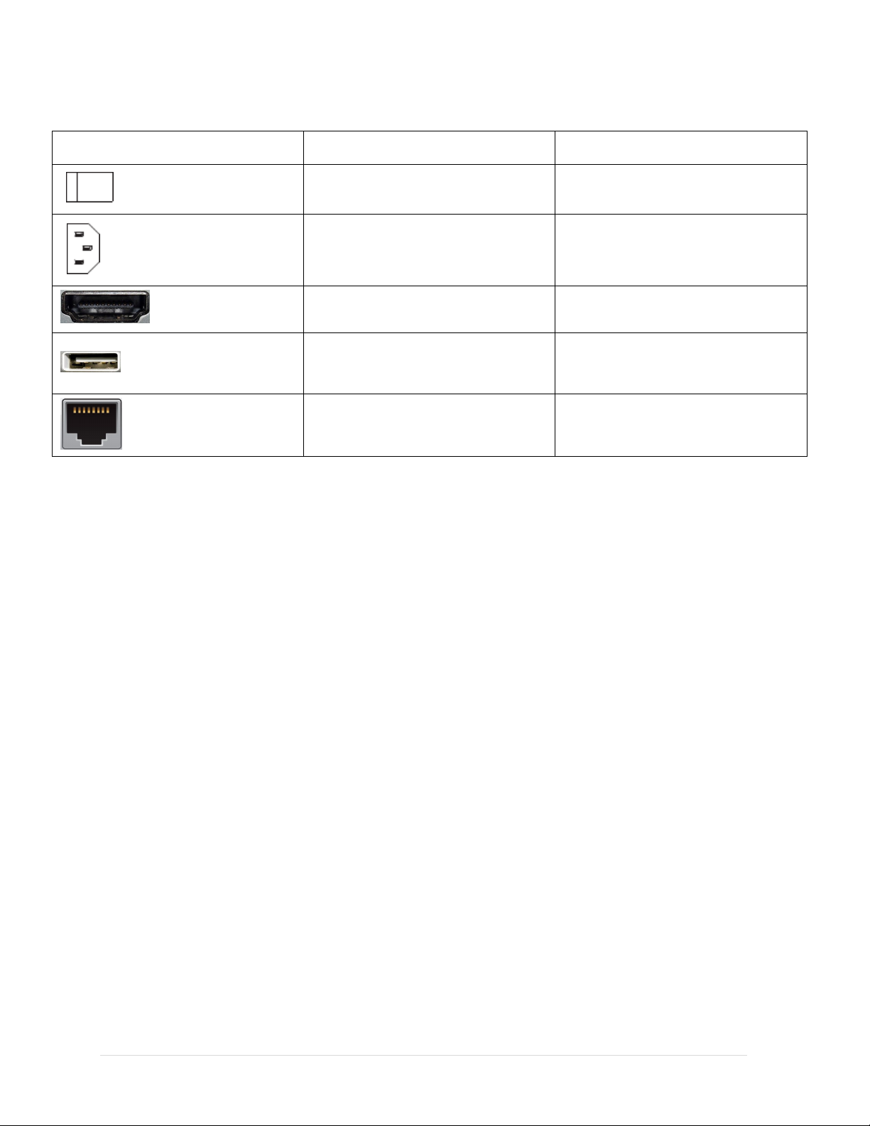
Please refer to the following sheet for detailed information.
Icon
Port Name Function
Power on-off button Power on-off button.
Power input port
Input AC 220V.
Backup Power input port
HDMI Port
HDMI Output
2USB Ports to connect USB
USB Port
Network Port
storage device, USB mouse.
4 Network Ports

Page 13
User Manual
1.2 Bidirectional Talk
External SATA port. It can connect to the
Connect to USB2.0 storage device , mouse,
COM
VGA video output port. Output analog video
1.2.1 Device-end to PC-end Device connection
Please connect the speaker or the pickup to the first audio input port in the device rear
panel. Then connect the earphone or the sound box to the audio output port in the PC.
Login the Web and then enable the corresponding channel real-time monitor.
Please refer to the following interface to enable bidirectional talk;
device of the SATA port. Please jump the
eSATA
RS232(RS-422
VGA
)
eSATA port
USB2.0 port.
RS232 debug
VGA video output
port
HDD when there is peripheral connected
HDD.
burner and etc..
It is for general COM debug to configure IP
address or transfer transparent COM data.
signal. It can connect to the monitor to
view analog video.

Page 14
User Manual
2 Local Basic Operation
2.1 Boot up and Shutdown
2.1.1 Boot up
Before the boot up, please make sure:
• The rated input voltage matches the device power on-off button. Please make
sure the power wire connection is OK. Then click the power on-off button.
• The external power is DC 12V/AC 100V-240V.
• Always use the stable current, if necessary UPS is a best alternative measure.
Please follow the steps listed below to boot up the device.
• Connect the device to the monitor and then connect a mouse.
• Connect power cable.
• Click the power button at the front or rear panel and then boot up the device.
After device booted up, the system is in multiple-channel display mode by
default.
2.1.2 Shutdown
Note
• When you see corresponding dialogue box “System is shutting down…” Do not
click power on-off button directly.
• Do not unplug the power cable or click power on-off button to shutdown device
directly when device is running (especially when it is recording.)
There are three ways for you to log out.
a) Main menu (recommended)
From Main Menu->Shutdown, select shutdown from dropdown list.
Click OK button, you can see device shuts down.
Page 15
User Manual
b) From power on-off button on the front panel or remote control
Press the power on-off button on the NVR front panel or remote control for more
than 3 seconds to shutdown the device.
c) From power on-off button on the rear panel.
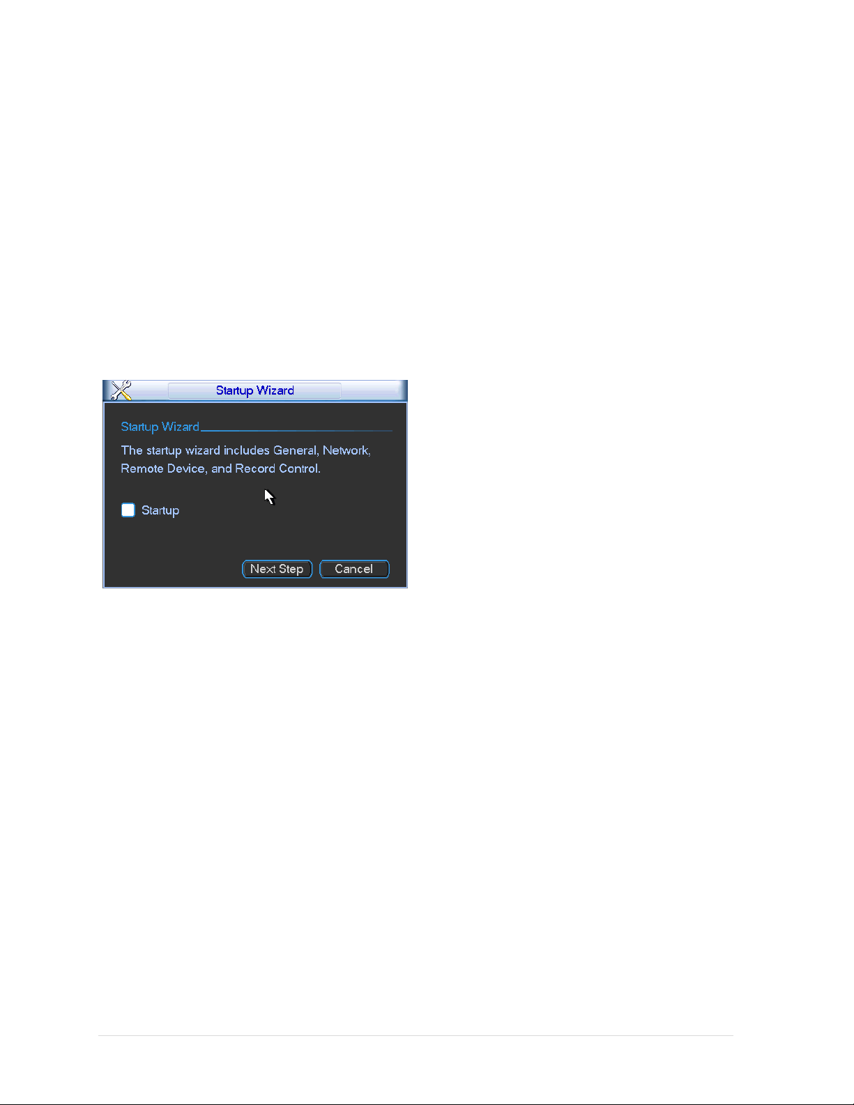
2.2 Startup Wizard
After device successfully booted up, it goes to startup wizard.
Click Cancel/Next button, you can see system goes to login interface.
Figure 2-1
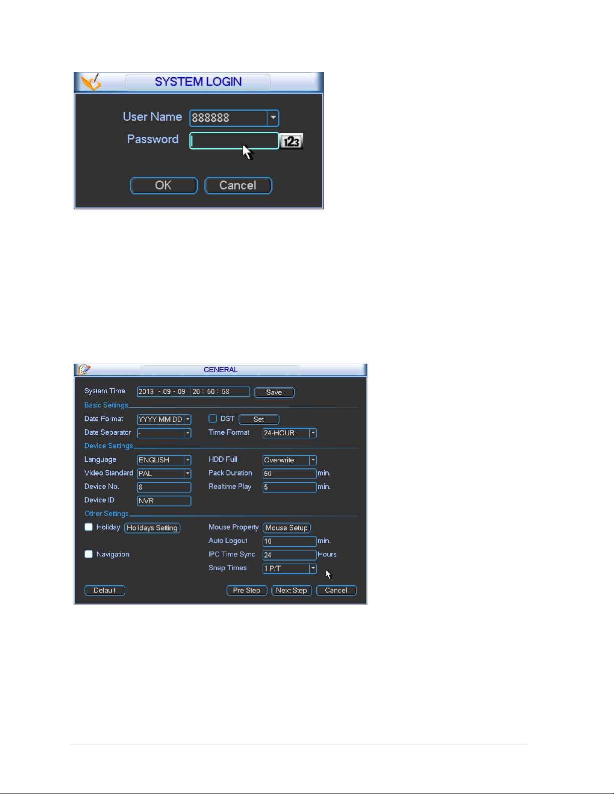
Click Cancel button or Next Step button, system goes to login interface. See Figure
2-2.System consists of four accounts:
• Username: admin. Password: admin. (administrator, local and network).
• Username: cita. Password: cita. (administrator, local only).
Page 16
User Manual
Figure 2-2
Note:
For security reason, please modify password after you first login.
Within 30 minutes, three times login failure will result in system alarm and five times
login failure will result in account lock!
Click OK button, you can go to General interface. See Figure 2-3.
Figure 2-3
Page 17
User Manual
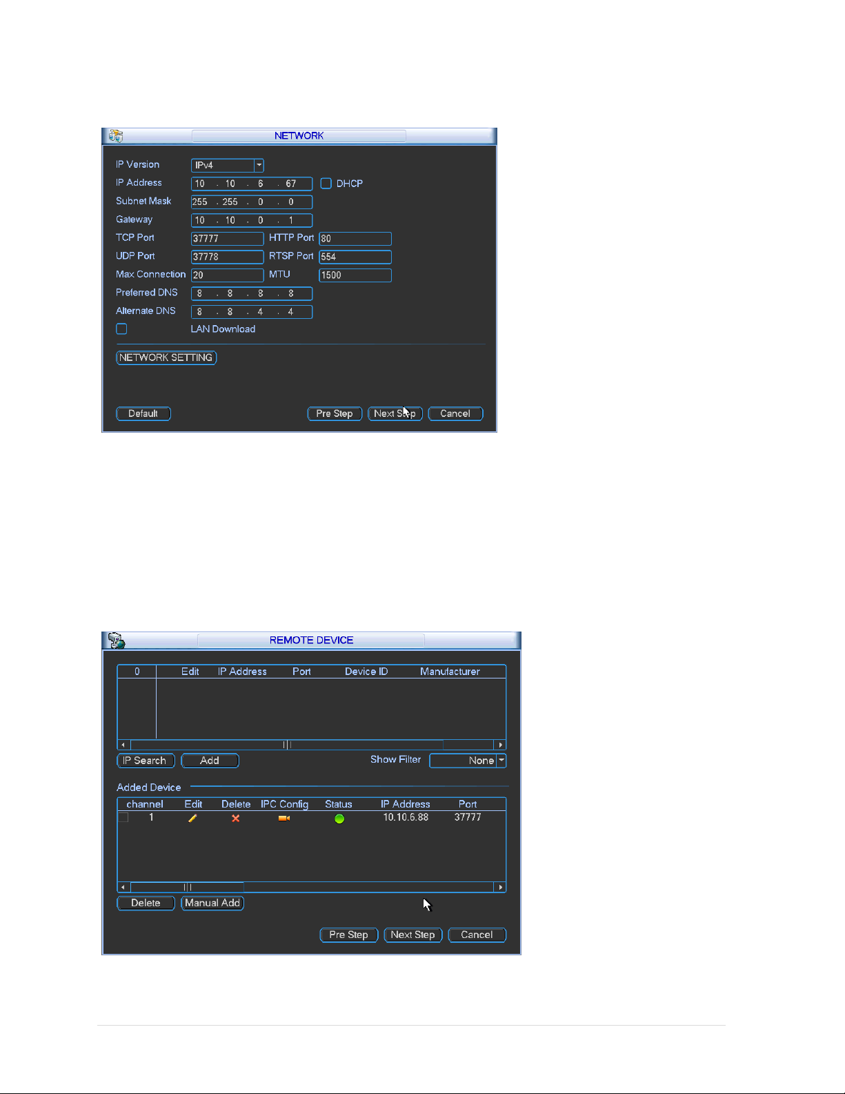
Click Next button, you can go to network interface. See Figure 2-4
Figure 2-4
Click Next button, you can go to remote device interface. See
Figure 2-5
For detailed information, please refer to chapter 2.3.
Page 18
User Manual
Figure 2-5
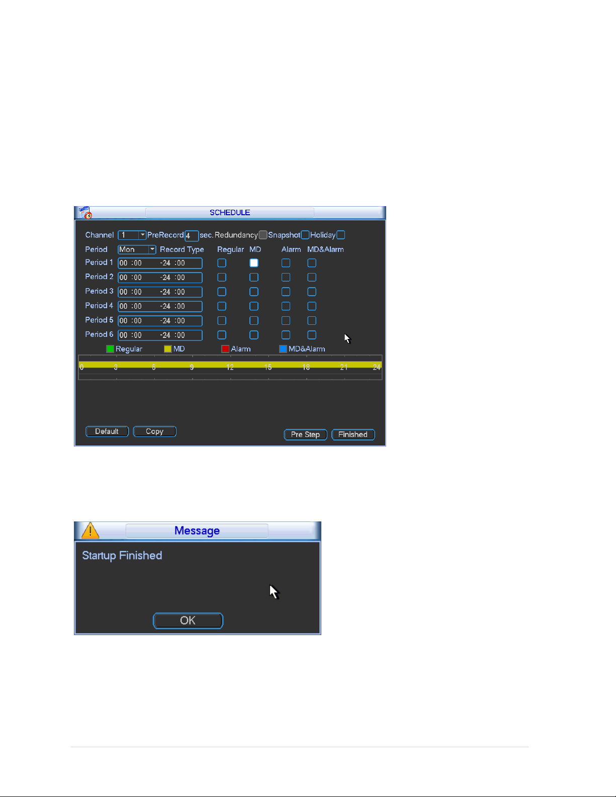
Click Next button, you can go to Schedule interface. See Figure 2-6.
For detailed information, please refer to chapter 2.6.2.
Figure 2-6
Click Finish button, system pops up a dialogue box. Click the OK button, the startup
wizard is complete. See Figure 2-7.
Figure 2-7
Page 19
User Manual
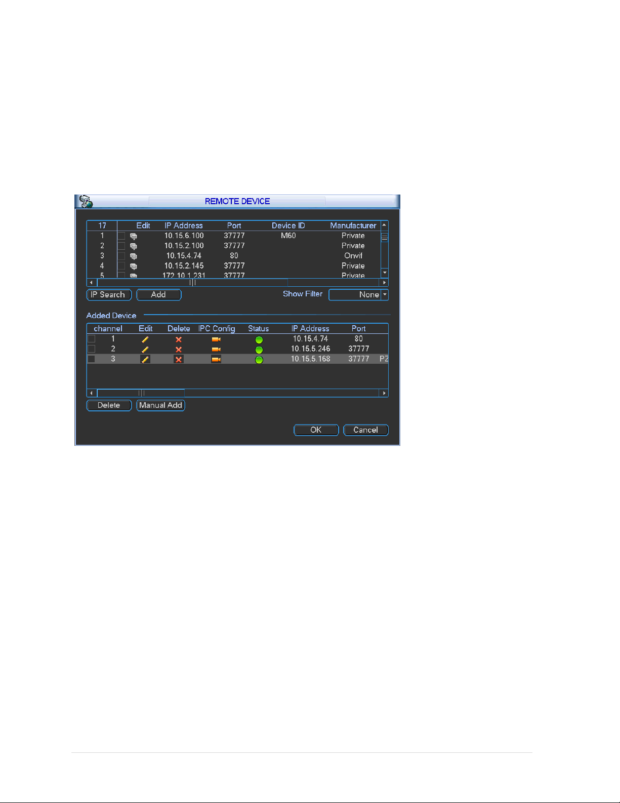
2.3 Remote Device
2.3.1 Remote Device Connection
From Main menu->Remote device or right click mouse on the preview interface and
then select remote device item, you can see the following interface. See Figure 2-8.
Figure 2-8
Click IP search button, you can view the searched IP addresses at the top pane of
the interface.
Double click an IP address or check one IP address and then click Add button, you
can add current device to the bottom pane of the interface. System supports batch
add function.
 Loading...