

CIT A2 Service Manual
RoHS Compliant
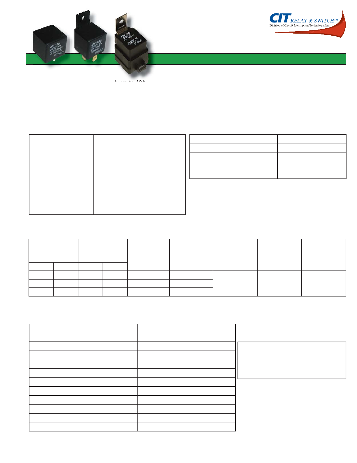
Features
• Large switching capacity up to 40A
• Small size and light weight
• PCB pin and quick connect mounting available
• Suitable for automobile and lamp accessories
• QS-9000, ISO-9002 Certifi ed Manufacturing
Contact Data
A2
26.0 x 26.0 x 24.5 (39.5) mm
Contact Arrangement 1A = SPST N.O.
1B = SPST N.C.
1C = SPDT
1U = SPST N.O. (2 terminals)
Contact Rating 1A : 40A @ 14VDC
1B : 30A @ 14VDC
1C : 40A @ 14VDC N.O. and
1C : 30A @ 14VDCN.C.
1U : 2x20A @ 14VDC
Coil Data
Coil Voltage
VDC
Rated Max 1.6W 1.9W
6 7.8 22.5 19 4.20 .6
24 31.2 360 303.2 16.80 2.4
Coil Resistance
Ω +/- 10%
Pick Up Voltage
VDC (max)
70% of rated
voltage
Contact Resistance < 30 milliohms initial
Contact Material AgSnO
Maximum Switching Power 630W
Maximum Switching Voltage 75VDC
Maximum Switching Current 40A
Release Voltage
VDC (min)
10% of rated
voltage
Coil Power
W
1.60 or 1.90 7 512 15.6 90 75.8 8.40 1.2
Operate Time
ms
2
Release Time
ms
General Data
Electrical Life @ rated load 100K cycles, typical
Mechanical Life 10M cycles, typical
Insulation Resistance 100M Ω min. @ 500VDC
Dielectric Strength, Coil to Contact 750V rms min. @ sea level
Contact to Contact 500V rms min. @ sea level
Shock Resistance 147m/s
Vibration Resistance 1.5mm double amplitude 10~40Hz
Terminal (Copper Alloy) Strength 8N (quick connect), 4N (PCB pins)
Operating Temperature -40
Storage Temperature -40
Solderability 260oC for 5 s
Weight 31g
Dimensions shown in mm. Dimensions are shown for reference purposes only. Specifi cations and availability subject to change without notice.
2
for 11 ms
o
C to +125oC
o
C to +155oC
page 77
Caution
1. The use of any coil voltage less than the
rated coil voltage may compromise the
operation of the relay.
www.citrelay.com
phone - 763.535.2339 fax - 763.535.2194

A2
Ordering Information
1. Series A2 1C S Q 12VDC 1.6
A2 standard
A2F with mounting fl ange
A2M with metal bracket
A2S with metal bracket and shroud
2. Contact Arrangement
1A = SPST N.O.
1B = SPST N.C.
1C = SPDT
1U = SPST N.O. (2 terminals)
3. Sealing Option
S = Sealed
C = Dust Cover
4. Termination
P = PCB Pins *not available with A2S
Q = Quick Connect
5. Coil Voltage
6VDC
12VDC
24VDC
6. Coil Power
1.6 = 1.6W
1.9 = 1.9W
7. Coil Suppression
Blank = Standard
D = Diode (1N4005) Cathode on “86” terminal
D1 = Diode (1N4004) Cathode on “86” terminal
R = Resistor (180Ω for 6VDC; 680Ω for 12VDC; 2700Ω for 24VDC)
2D = 2 Diodes (1N4005)
DR = Diode & Resistor Cathode on “86” terminal (1N4005 & 180Ω for 6VDC; 680Ω for 12VDC; 2700Ω for 24VDC)
** Consult factory if other values are needed
*not available with A2S
Dimensions shown in mm. Dimensions are shown for reference purposes only. Specifi cations and availability subject to change without notice.
Dimensions
Units = mm
A2 with PC Pins A2 with Quick Connects
www.citrelay.com
phone - 763.535.2339 fax - 763.535.2194
page 78
 Loading...