

Cissell VSBMAN61, A Owner's Manual

Vacuum
Spotting
Board
Model A
OWNERS MANUAL
CISSELL MANUFACTURING COMPANY
HEADQUARTERS PHONE: (502) 587-1292
831 SOUTH FIRST ST. SALES FAX: (502) 585-3625
P.O. BOX 32270 SERVICE/PARTS FAX: (502) 681-1275
LOUISVILLE, KY 40232-2270
THIS MANUAL MUST BE GIVEN TO THE EQUIPMENT OWNER.
MAN61 (ECN5680) 10/99 WB 2C
Page1

WARRANTY
The Cissell Manufacturing Company (Cissell) warrants all new equipment (and the original parts thereof) to be free from
defects in material or workmanship for a period of one (1) year from the date of sale thereof to an original purchaser for
use, except as hereinafter provided. With respect to non-durable parts normally requiring replacement in less than one (1)
year due to normal wear and tear, including, but not limited to, cloth goods, valve discs, hoses, and iron cords, and with
respect to all new repair or replacement parts for Cissell equipment for which the one (1) year warranty period has expired,
or for all new repair or replacement parts for equipment other than Cissell equipment, the warranty period is limited to ninety
(90) days from date of sale. The warranty period on each new replacement part furnished by Cissell in fulfillment of the
warranty on new equipment or parts shall be for the unexpired portion of the original warranty period on the part replaced.
With respect to electric motors, coin meters and other accessories furnished with the new equipment, but not manufactured
by Cissell, the warranty is limited to that provided by the respective manufacturer.
Cissell's total liability arising out of the manufacture and sale of new equipment and parts, whether under the warranty or
caused by Cissell's negligence or otherwise, shall be limited to Cissell repairing or replacing, at its option, any defective
equipment or part returned f.o.b. Cissell's factory, transportation prepaid, within the applicable warranty period and found
by Cissell to have been defective, and in no event shall Cissell be liable for damages of any kind, whether for any injury
to persons or property or for any special or consequential damages. The liability of Cissell does not include furnishing (or
paying for) any labor such as that required to service, remove or install; to diagnose troubles; to adjust, remove or replace
defective equipment or a part; nor does it include any responsibility for transportation expense which is involved therein.
The warranty of Cissell is contingent upon installation and use of its equipment under normal operating conditions. The
warranty is void on equipment or parts; that have been subjected to misuse, accident, or negligent damage; operated under
loads, pressures, speeds, electrical connections, plumbing, or conditions other than those specified by Cissell; operated or
repaired with other than genuine Cissell replacement parts; damaged by fire, flood, vandalism, or such other causes beyond
the control of Cissell; altered or repaired in any way that effects the reliability or detracts from its performance, or; which
have had the identification plate, or serial number, altered, defaced, or removed.
No defective equipment or part may be returned to Cissell for repair or replacement without prior written authorization from
Cissell. Charges for unauthorized repairs will not be accepted or paid by Cissell.
CISSELL MAKES NO OTHER EXPRESSED OR IMPLIED WARRANTY, STATUTORY OR OTHERWISE,
CONCERNING THE EQUIPMENT OR PARTS INCLUDING, WITHOUT LIMITATION, A WARRANTY OF
FITNESS FOR A PARTICULAR PURPOSE, OR A WARRANTY OF MERCHANTABILITY. THE
WARRANTIES GIVEN ABOVE ARE EXPRESSLY IN LIEU OF ALL OTHER WARRANTIES,
EXPRESSED OR IMPLIED. CISSELL NEITHER ASSUMES, NOR AUTHORIZES ANY PERSON TO
ASSUME FOR IT, ANY OTHER WARRANTY OR LIABILITY IN CONNECTION WITH THE
MANUFACTURE, USE OR SALE OF ITS EQUIPMENT OR PARTS.
For warranty service, contact the distributor from whom the Cissell equipment or part was purchased. If the distributor
cannot be reached, contact Cissell.
Page2

TABLE OF CONTENTS
Warranty ............................................................................................................................... 2
Table of Contents .................................................................................................................. 3
Dimension Drawings ............................................................................................................ 4
Installation Illustration.......................................................................................................... 5
Specifications........................................................................................................................ 6
Installation of Steam Lines ................................................................................................... 6
Mechanical Operation........................................................................................................... 7
Mechanical Maintenance ...................................................................................................... 7
Operating Instructions ..........................................................................................................8
Adjustment of Wet and Dry Steam Valves ........................................................................... 9
Illustrated Parts
Overall View ......................................................................................................................... 10-11
Large Board .......................................................................................................................... 12
Swinging Sleeve Board ........................................................................................................ 13
Spotting Gun and Hose......................................................................................................... 14
Chemical Tray ...................................................................................................................... 15
Steam Chamber and Valve Assembly ................................................................................... 16-17
Base Assembly ...................................................................................................................... 18
Central Air Vacuum ..............................................................................................................19
Steam Vacuum ...................................................................................................................... 20
Head Valves & Service Instructions ..................................................................................... 21
Trouble Shooting Chart ........................................................................................................ 22
Page3
VACUUM SPOTTING BOARD
MODEL A
GENERAL SPECIFICATIONS
Page4
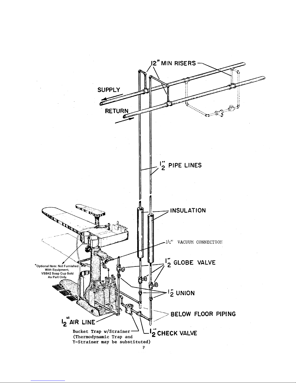
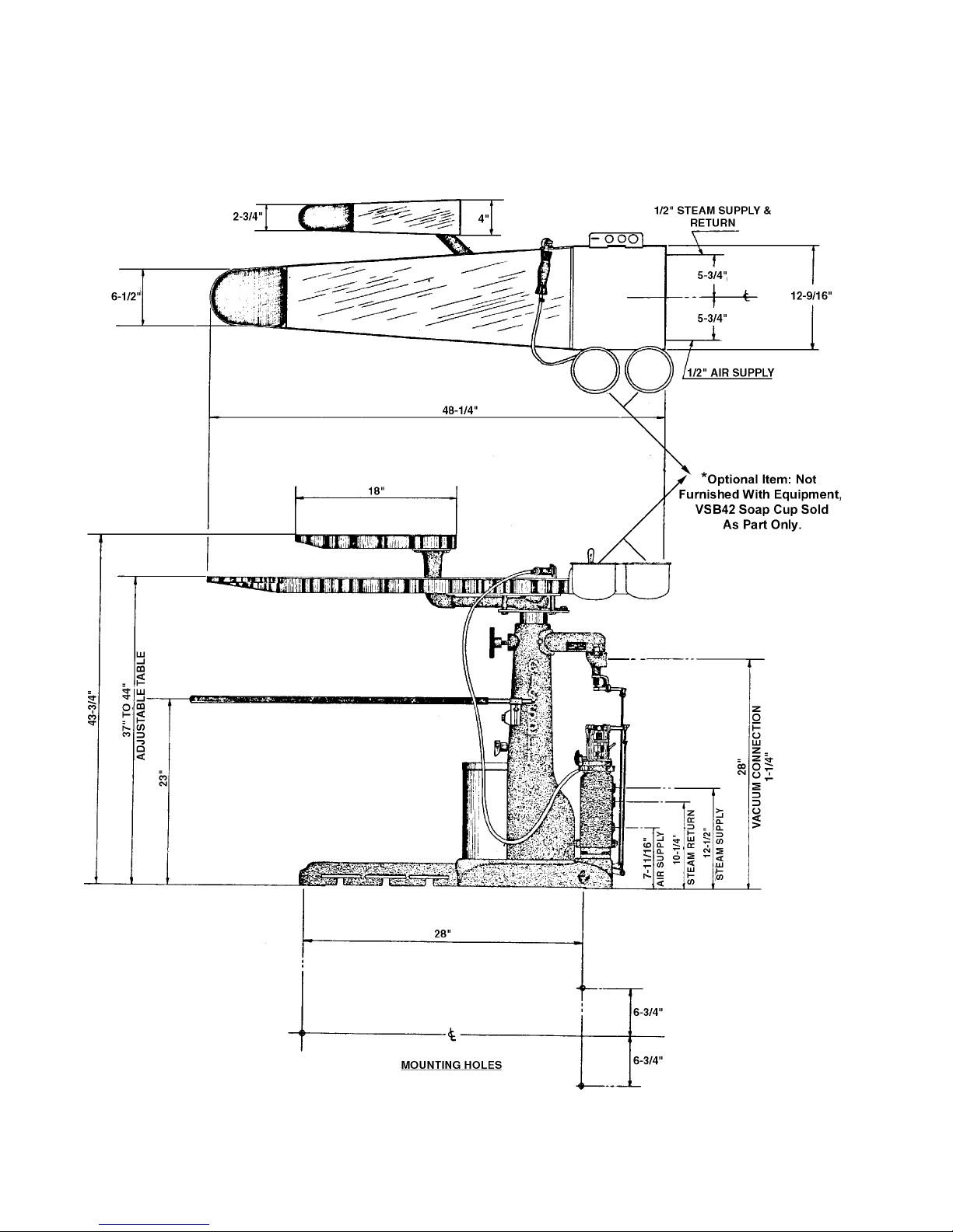
VACUUM SPOTTING BOARD
MODEL A
INSTALLATION ILLUSTRATION
USE IMPULSE TRAP AND
STRAINER FOR WET
LINE CONDITIONS
Page5

SPECIFICATIONS - VACUUM SPOTTING BOARD
Net Weight ........................................................................................... 235 lb (107 kg)
Domestic Shipping Weight (1 Carton) ................................................ 280 lb (127 kg)
Export Shipping Weight (1 Box) ......................................................... 435 lb (197 kg)
Export Shipping Dimensions .............................................................. 47" (1194 mm) H, x 53" 1346 mm) L,
x 20" (508 mm) W
Export Crate Volume ........................................................................... 29 Cu. Ft. (0.821 m3)
Floor Space .......................................................................................... 20" (508 mm) x 48" (1219 mm)
Table Height (Adjustable) ................................................................... 37" (940 mm) to 44" (1118 mm)
Length of Working Surface.................................................................. 38" (965 mm)
Width at Front End of Large Board ..................................................... 6 1/2" (165 mm)
Width at Rear End of Large Board ...................................................... 12 1/2" (318 mm)
Width at Front End of Swinging Sleeve Board ................................... 2 1/2" (64 mm)
Width at Rear End of Swinging Sleeve Board .................................... 4" (102 mm)
Boiler Horsepower (approximate) ....................................................... 1 1/4
Operating Steam Pressure.................................................................... 100 psi max. (6.9 Bars)
Steam Supply Connection ................................................................... 1/2" Pipe (DN15)
Steam Return Connection.................................................................... 1/2" Pipe (DN15)
Vacuum Outlet Connection ................................................................. 1 1/4" Pipe (DN32)
Vacuum Requirement .......................................................................... 1 Press capacity (1/2 Hp.)
NOTE: An air compressor is required for the heated compressed air feature. A 1 hp. (746W) compressor
delivering 6 (2.8 I/s) to 8 (3.8 I/s) cfm at 80 (356N) to 125 (556N) lbs. pressure will accomodate one board;
a 1 1/2 hp. (1119W) compressor will accomodate two boards.
INSTALLATION OF STEAM LINES
Steam supply line must fall towards machine (without water pockets.) Connect spotting board to steam
supply line with union, globe valve and 12" (or more) riser, as illustrated on previous page. If spotting board
is located at the end of stream line, extend line at least 4 feet beyond machine, and install a by-pass trap and
check valve as illustrated in dotted lines; if gravity return, omit trap.
Steam return line must fall towards boiler (without water pockets). Connect spotting board to steam return
line with a swing connection, unions, strainer, trap, check valve and 12" (or more) riser as illustrated on rever
se side. Inspect trap carefully for inlet and outlet markings and install swing connection, trap, and check valve
as close to machine as possible with trap as close to floor as practical.
Use a separate trap for the spotting board; keep it clean and in good working condition for best performance.
If steam line is gravity returned to boiler, omit trap.
IMPORTANT: Before installing trap and connecting steam return line, open globe valve in steam supply
connection and flush pipe dope, borings and other foreign matter, from steam connections and steam chamber
within spotting board. Failure to do this may later cause trap trouble.
Page6

VACUUM SPOTTING BOARD
VACUUM SPOTTING BOARD MECHANICAL OPERATION
Vacuum draws uniformly through the screen area on the nose of the board and the nose of the swinging sleeve board
by pressing on the middle foot pedal. By pushing the swinging sleeve board back, the vacuum operates on the nose of
the large board. By pulling the swinging sleeve board forward, vacuum operates on its nose. Changing the position of
the swinging sleeve board operates a self-cleaning valve which gives full unrestricted passage for vacuum at all times.
Steam is released from the spotting gun by pressing the left foot pedal as follows: a slight touch releases a feather of
dry steam; partly down releases dry steam; half-way down releases moist steam; completely down releases wet steam.
CAUTION: The steam emitted from the spray gun is very hot. Burns to face and hands may result from contact with
live steam.
Hot air for drying is released from the spotting gun by pressing the right foot pedal.
Automatic check valve releases all chemicals and water from vacuum chamber to an extra large drain recepticle. No
pipe line or sewage connection is needed.
Adjustable board for operator comfort from 37" to 44" in height. Loosen knob near top of the column, slide top
assembly up or down to desired height, then tighten knob.
MECHANICAL MAINTENANCE
CLEANING LARGE PAN ASSEMBLY
Lift chemical tray and large vitrelite glass from board.
Tap off nose band and perforated metal, clean with steam gun.
Clean pan of all dirt, lint and chemicals.
Open drain holes with a hairpin or pointed instrument. It is important that these drain holes are open in order that the
vacuum can extract any liquids that form in the pan.
CLEANING SWINGING ARM ASSEMBLY
Lift out small green vitrelite glass by finger hole at back of pan.
Remove perforated metal.
Clean with steam gun.
Clean pan or all dirt, lint and chemicals (use steam gun).
Open drain holes (in pan) with a hairpin or pointed instrument.
VACUUM SEAL
The rubber air-foam gasket around pipe of top assembly at top of column is a seal to help create a stronger vacuum.
Should this gasket become loose, re-cement into position.
CHECK VALVE
Inspect and clean check valve located above drain receptacle. Liquids separated from the vacuum exhaust within the
column are automatically drained from board by check valve.
Lift drain receptacle up and out for emptying.
UPPER AND LOWER SLIDE
A few drops of oil on the upper and lower slides of the swinging arm assembly will permit easier
operation.
Page7
 Loading...